

Page 1

| FCC Part 15 Notice |
This equipment has been tested and found to comply with the
limits for a Class B digital device, pursuant to part 15 of the
FCC Rules. Operation is subject to the following two conditions:
(1) this device may not cause harmful interference, and (2) this
device must accept any interference received, including
interference that may cause undesired operation. Class B limits
are designed to provide reasonable protection against harmful
interference in a residential installation. This equipment
generates, uses, and can radiate radio frequency energy, and,
if not installed and used in accordance with the instructions,
may cause harmful interference to radio communications.
However, there is not guarantee that interference will not occur
in a particular installation. If this equipment does cause harmful
interference to radio or television reception, which can be
determined by turning the equipment off and on, the user is
encouraged to try to correct the interference by one or more of
the following measures:
• Reorient the receiving antenna.
• Increase the separate between the equipment and the
receiver.
• Connect the equipment into an outlet on a circuit
different from that to which the receiver is connected.
• Consult the dealer or an experienced radio/TV technician
for help.
| Copyright |
Copyrightⓒ 2004 by Corecess All rights Reserved.
No part of this book shall be reproduced, stored in a
retrieval system, or transmitted by any means, electronic,
mechanical, photocopying, recording, or otherwise,
without written permission from the publisher.
The specifications and information regarding the products
in this manual are subject to change without notice.
| Trademark Credit |
Corecess 3115 is a registered trademark of Corecess Inc.
Windows is registered trademark of Microsoft Corp.
Corecess Inc.
500-2, Sangdaewon-dong, Jungwon-ku, Sungnam-city,
Kyungki-do, Korea, 462-120
TEL: +82-31-739-6600 FAX: +82-31-739-6622
http://www.corecess.com
Page 2
Using This Document
Thank you for using the product of Corecess. This manual will show you how to set up the
Corecess 3115 ADSL modem, and how to customize its configuration to get the most out of your
new product.
This user manual uses the following conventions:
Note: Introduces useful item for the use of product, reference, and its related materials.
Caution: Explains possible situations or conditions of improper operation and possibility of losing data
and provides suggestions how to deal with those cases.
Table of Contents
Introduction
Key Features ............................................................. 4
System Requirement .................................................
Types of ADSL Services ............................................
Getting to Know the Corecess 3115
Unpacking the Box ..................................................... 7
Front Panel .................................................................
Rear Panel .................................................................
Connecting Hardware
Basic Procedure of Cabling .....................................
Optional Procedure of Cabling ................................
Connecting Power ...................................................
.....................................................................
.........................
................................................
4
4
5
7
8
9
10
11
12
13
Configuring Your Computers
Before you begin ..................................................... 14
Windows XP ............................................................
Windows 2000/NT ...................................................
Windows 95/98/ME .................................................
Configuring a Computer Connected to the USB Port ....
Troubleshooting
...........................................................
Technical Specifications
....................................
............................................
14
14
15
16
17
21
23
Page 3

Introduction
The Corecess 3115 is an Asymmetric Digital Subscriber Line (ADSL) modem used for home
connectivity to an ADSL service provider network. The Corecess 3115 ADSL modem receives
adaptive data rates of up to 8Mbps downstream and transmits 1Mbps upstream.
Key Features
The Corecess 3115 ADSL modem provides the following key features:
y
Internal ADSL modem for high-speed Internet access
y 10/100Base-T Ethernet router to provide Internet connectivity to all computers on your LAN
y USB port for connecting a USB-enabled PC (optional)
y Network address translation (NAT), Firewall, and IP filtering functions to provide security for
your LAN
y Network configuration through DHCP Server and DHCP Relay
y Services including IP route and DNS configuration, RIP, and IP and DSL performance
monitoring
y Configuration program you access via an HTML browser
System Requirement
In order to use the Corecess 3115, you must have the following:
y
ADSL service up and running on your telephone line, with at least one public Internet address
for your computer.
y
One or more computers each containing an Ethernet 10Base-T/100Base-T network interface
card (NIC) and/or a single computer with a USB port.
y
An Ethernet hub/switch, if you are connecting the device to more than one computer on an
Ethernet network.
y For system configuration using the supplied web-based program: a web browser such as
Internet Explorer v5.0 or later, or Netscape v4.7 or later.
4
Corecess 3115 Installation Guide
Page 4
Types of ADSL Service
The Corecess 3115 supports the following types of ADSL service.
Bridge Mode
The Corecess 3115 in bridge mode behaves like a wire which is connecting a local PC directly to a
service provider’s network.
Router Mode
The Corecess 3115 in router mode can be organized as a small LAN using NAT and DHCP server
function with IP routing. It allows multiple PCs to communicate and share the resource using only
one ADSL line. There are three types of router mode: PPPoA/PPPoE, Static IP, and Dynamic IP.
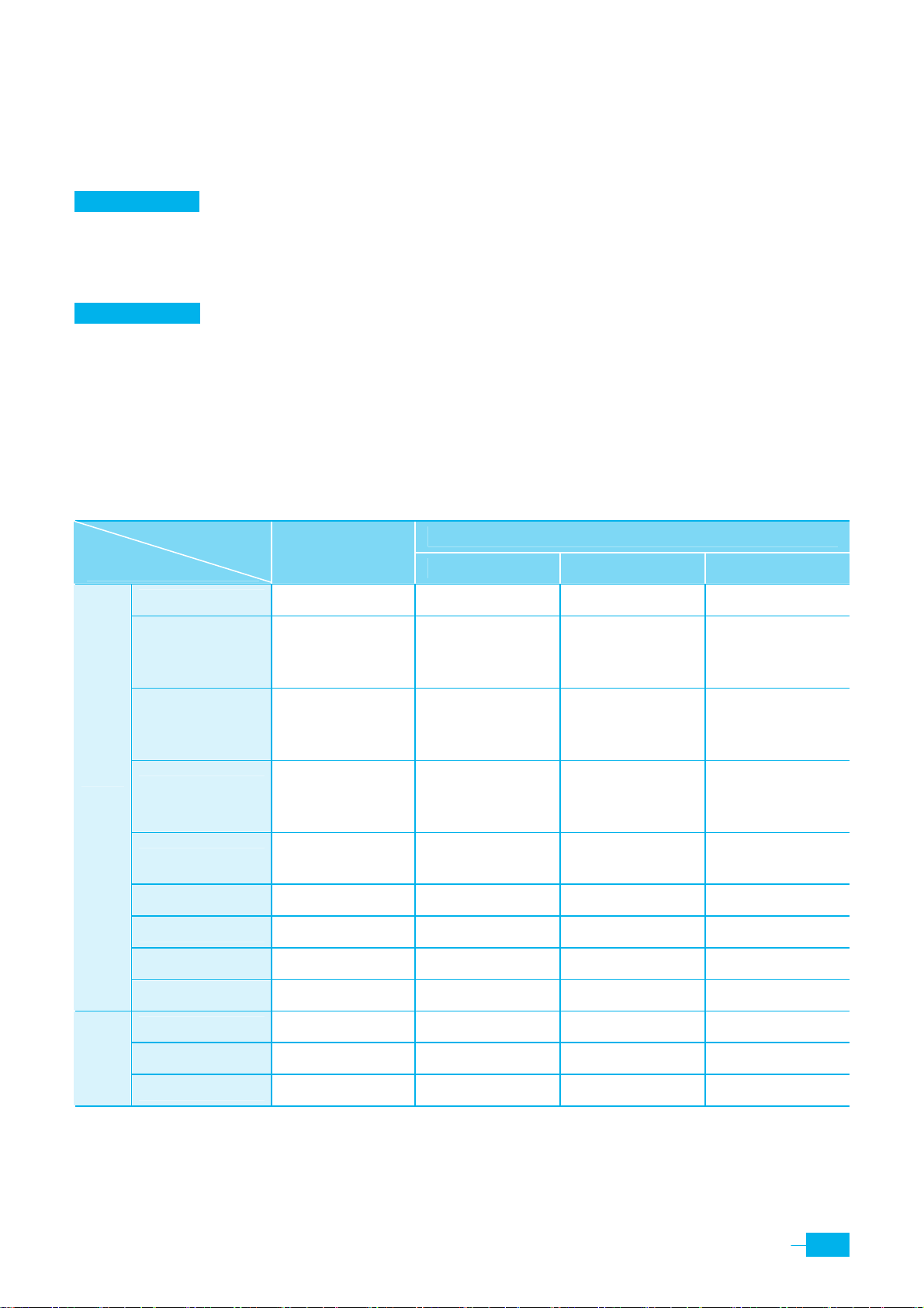
The following table shows the typical configuration for using the Corecess 3115 in bridge mode or
router mode.
ADSL Service
Configuration
Static IP Address N/A
Subnet Mask N/A
WAN
Encapsulation
Bridge Mode
PPPoA/PPPoE Static IP Dynamic IP
VPI/VCI Provided by ISP Provided by ISP Provided by ISP Provided by ISP
N/A
(Automatically
assigned by ISP)
N/A
(Automatically
assigned by ISP)
Default
Gateway
Bridge Enabled Disable Disable Disable
N/A
1483 Bridged IP
LLC
N/A
(Automatically
assigned by ISP)
PPPoA VC-Mux/
PPPoE LLC
Router Mode
Provided by ISP
Provided by ISP
Provided by ISP
1483 Bridged IP
LLC
N/A
(Automatically
assigned by ISP)
N/A
(Automatically
assigned by ISP)
N/A
(Automatically
assigned by ISP)
1483 Bridged IP
LLC
LAN
PPP User Name N/A Provided by ISP N/A N/A
PPP Password N/A Provided by ISP N/A N/A
DHCP Client Disable Disable Disable Enabled
IP Address N/A 10.0.0.2 (Default) 10.0.0.2 (Default) 10.0.0.2 (Default)
Subnet Mask N/A 255.0.0.0 (Default) 255.0.0.0 (Default) 255.0.0.0 (Default)
DHCP Server N/A Enabled Enabled Enabled
(continued)
5
Page 5

ADSL Service
Configuration
NAT N/A NAPT NAPT NAPT
Router Mode
Bridge Mode
PPPoA/PPPoE Static IP Dynamic IP
DNS N/A
N/A
(Automatically
assigned by ISP)
Provided by ISP
N/A
(Automatically
assigned by ISP)
6
Corecess 3115 Installation Guide
Page 6
Getting to Know the Corecess 3115
Unpacking the Box
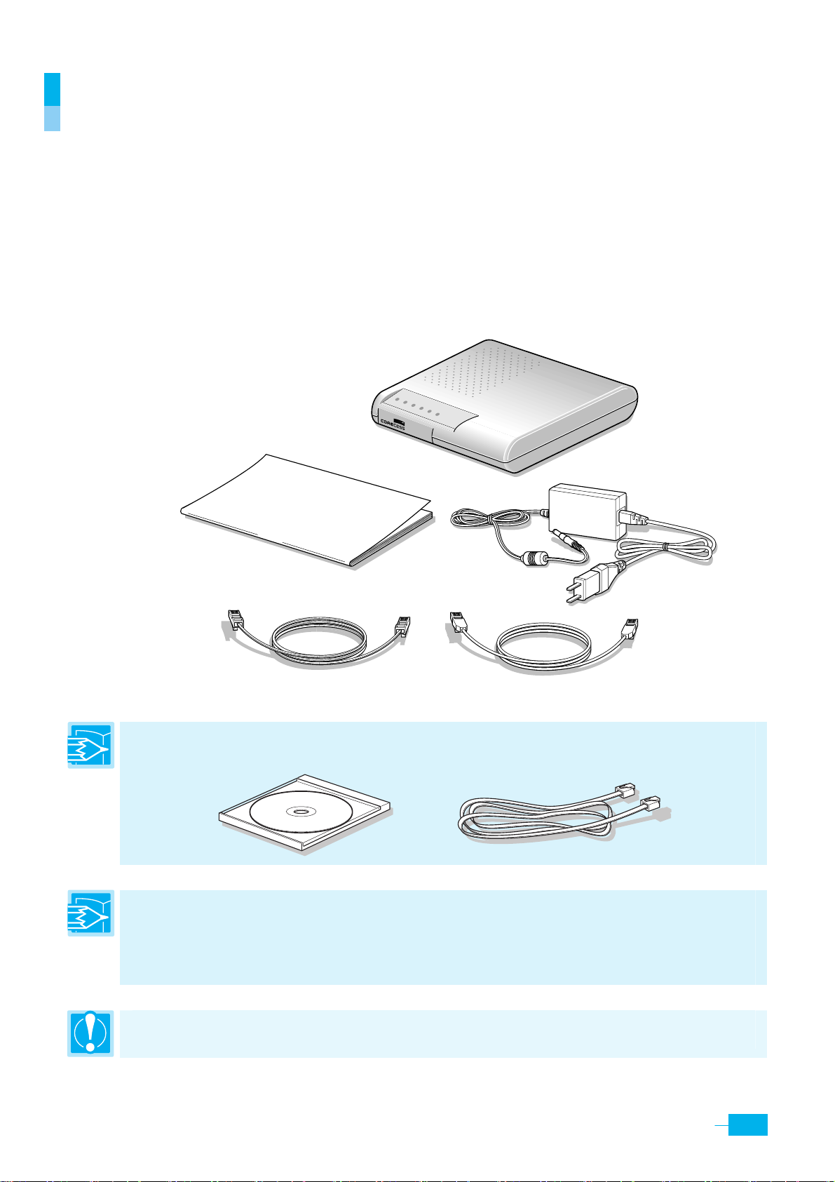
Check the shipping carton carefully to ensure that the contents include the items you ordered.
y
Corecess 3115 ADSL modem
y
Power adapter and power cord
Ethernet cable (“straight-through” type)
y
Standard phone/DSL line cable
y
y
Installation guide (this document)
PWR
LINK
Corecess3115
NET
ACT
LAN
DATA
Corecess 3115
Power adpater
Installation guide
Power cord
Phone/DSL line cable(RJ-11)
Ethernet cable (straight-through type)
Note: If you purchase the Corecess 3115 model which has an USB port, the following optional USB
cable and installation CD are included in the package:
Installation CD
USB cable
Note: The following hardware is not provided but neccssary to install and configure the Corecess
3115. Before installing the Corecess 3115, prepare the following hardware:
y Micro-filter or splitter (provided separately by your service provider)
y PC with Ethernet port or adapter (optional)
Caution: To reduce the risk of fire, use only No. 26AWG or larger telecommunication line cord.
7
Page 7
Front Panel
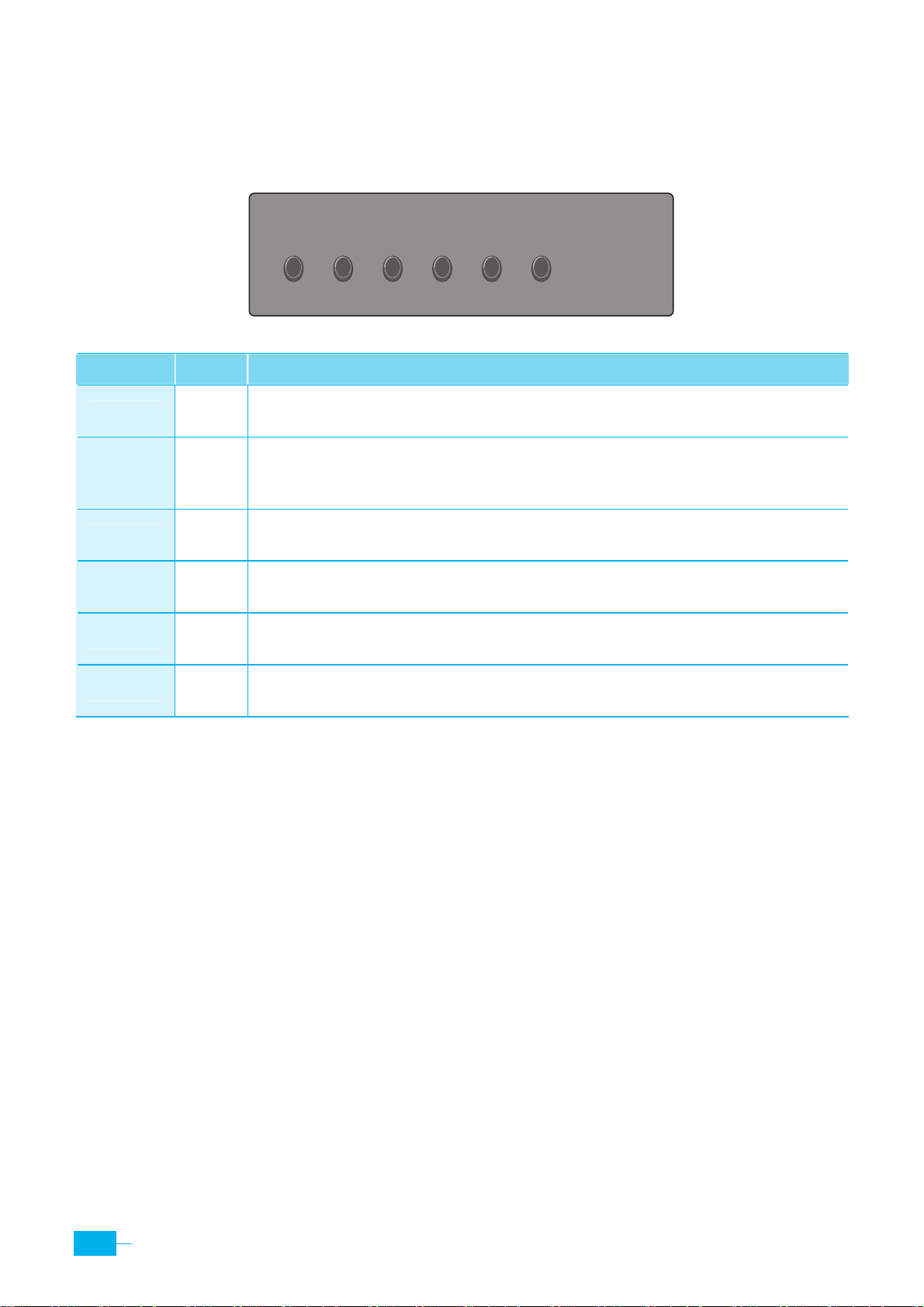
The front panel contains lights called LEDs that indicate the status of the unit.
Label Color Function
PWR
LINK
NET
ACT
LAN
DATA
PWR Green
LINK Green
NET Green
ACT Green
LAN Green
DATA Green
On : The Corecess 3115 is powered on.
Off : The Corecess 3115 is powered off.
On : ADSL link is established and active.
Flash : The Corecess 3115 is trying to establish ADSL link.
Off : No ADSL link.
On : WAN link is established and active.
Off : No WAN link.
Flash : ADSL data activity occurs (may appear solid when data traffic is heavy).
Off : No ADSL data activity.
On : LAN link is established and active.
Off : No LAN link.
Flash : LAN data activity occurs (may appear solid when data traffic is heavy).
Off : No LAN data activity.
8
Corecess 3115 Installation Guide
Page 8
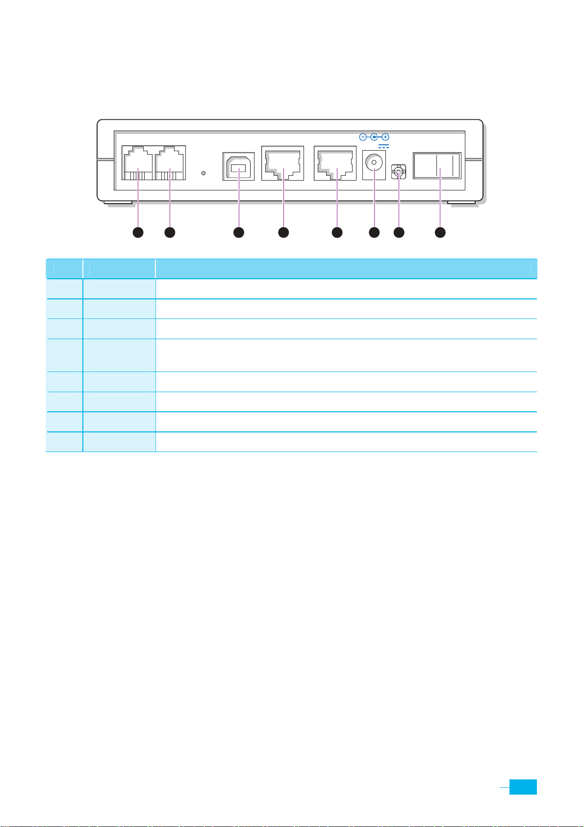
Rear Panel
The rear panel contains the ports for the unit’s data and power connections.
LINE
1 2 3 4 5 6 7 8
No. Name Function
n PHONE* Connects to a telephone.
CONSOLUSB LANPHONE
5V DC
OFF ON
o LINE Connects the device to a telephone jack for DSL communication.
p USB* Connects to the USB port on your PC.
q LAN
r CONSOL* Connects the device to a console terminal.
s DC IN Connects to the supplied power converter cable.
t (F/G) * Connects to Frame Ground for earthing.
u OFF/ON Switches the unit on and off.
※ The parts with * in the ‘Name’ field are optional. They could be provided or not according to the Corecess 3115
model which you have purchased.
Connects the device to your PC’s Ethernet port, or to the uplink port on your
LAN’s hub, using the cable provided.
9
Page 9
r
r
r
A
Connecting Hardware
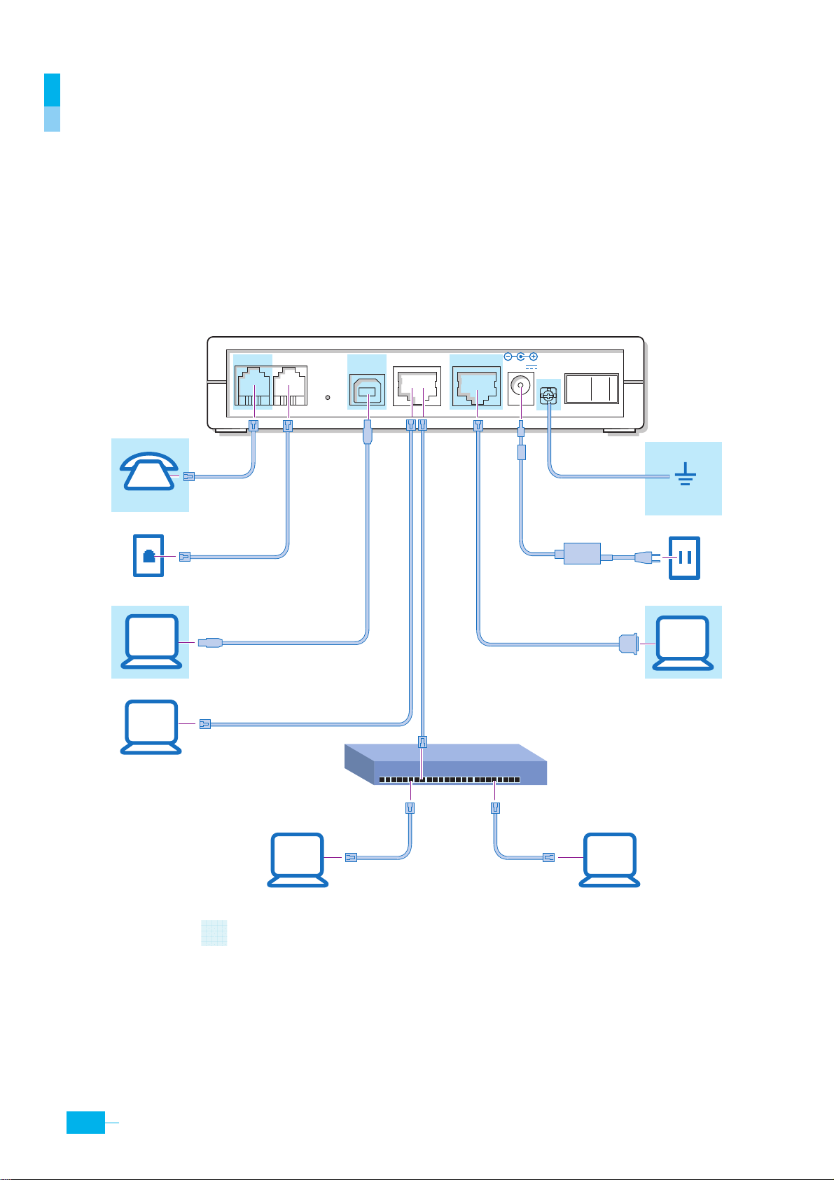
The Corecess 3115 supports both the POTS splitter and micro-filter phone configurations. Before
cabling the Corecess 3115, verify your configuration with your service provider. This section
describes how to connect the Corecess 3115 to the phone jack, the power outlet, and your
computer or network.
The following figure illustrates the hardware connections. The layout of the ports on your device
may vary from the layout shown. Refer to the steps that follow for specific instructions.
LINE
CONSOLUSB LANPHONE
5V DC
OFF ON
Earth
Phone
Phone cable
Powe
adapte
DSL cable
USB cable
Console cable
PC
Ethernet cable
o
ETHERNET connection: n or o
n
Console terminal
PC
Hub o
switch (for local area)
The parts covered ※ with are optional.
PC
Ethernet cable
Ethernet cable
PC
<네모가 with 뒤로 가도록 해주세요.>
10
Corecess 3115 Installation Guide
Page 10
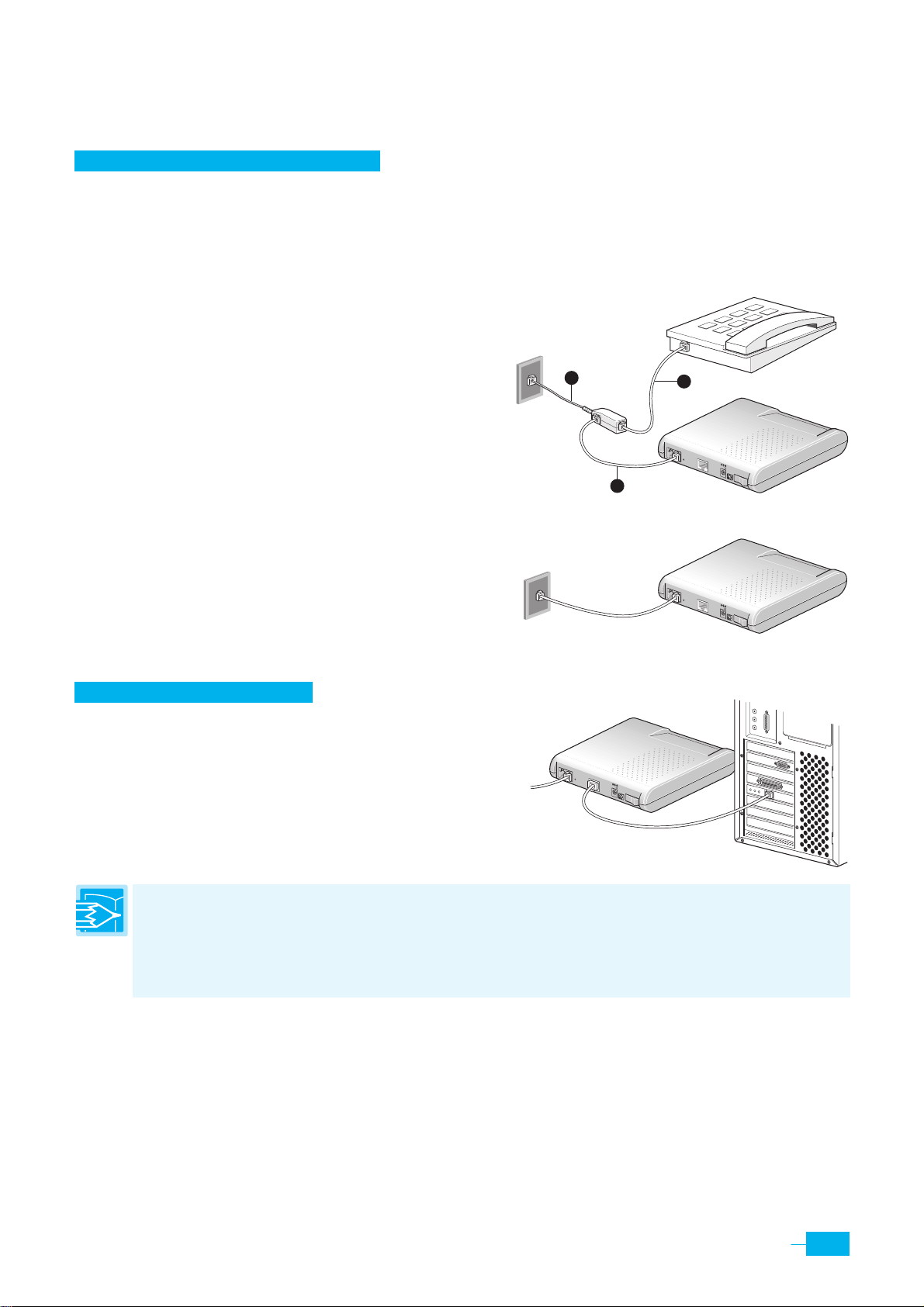
Basic Procedure of Cabling
Connecting ADSL Line (LINE Port)
If the Corecess 3115 doesn’t have the PHONE port:
n Unplug the telephone line from the wall receptacle and plug the line end of the micro-filter to
the wall phone jack.
o Connect the telephone cable that was unplugged
from step 1 to the
p Connect the provided phone/DSL cable to the
Modem
port of the micro-filter and then connect the
other end of the cable to the
Phone port of the micro-filter.
LINE port of the
Corecess 3115.
<위 그림에서 PHONE 포트를 삭제해주세요.>
If the Corecess 3115 has the PHONE port:
Unplug the telephone line from the telephone and
plug the line to the
LINE port of the Corecess 3115.
Connecting PC (LAN Port)
If you use the Ethernet adapter, connect the provided
Ethernet cable to the
then connect the other end of the cable to
LAN port of the Corecess 3115 and
Ethernet port on
PHONE
1
3
1
LINE
LAN
5V DC
OFF
2
PHONE
LI
NE
LAN
5V DC
OFF
ON
PHONE
LINE
LAN
5V DC
OFF
ON
ON
the NIC installed to your PC.
Note: If you are connecting a LAN to the Corecess 3115, you must use a “crossover” Ethernet cable
(not provided) to attach a regular hub or switch port. The crossover cable is wired differently than the
cable you would use to connect to a hub. When you compare the colored wires on each end of a
straight-through cable, they will be in the same sequence; on crossover cables, they will not. Contact
your ISP for assistance.
<위 그림에서 PHONE 포트를 삭제해주세요.>
11
Page 11
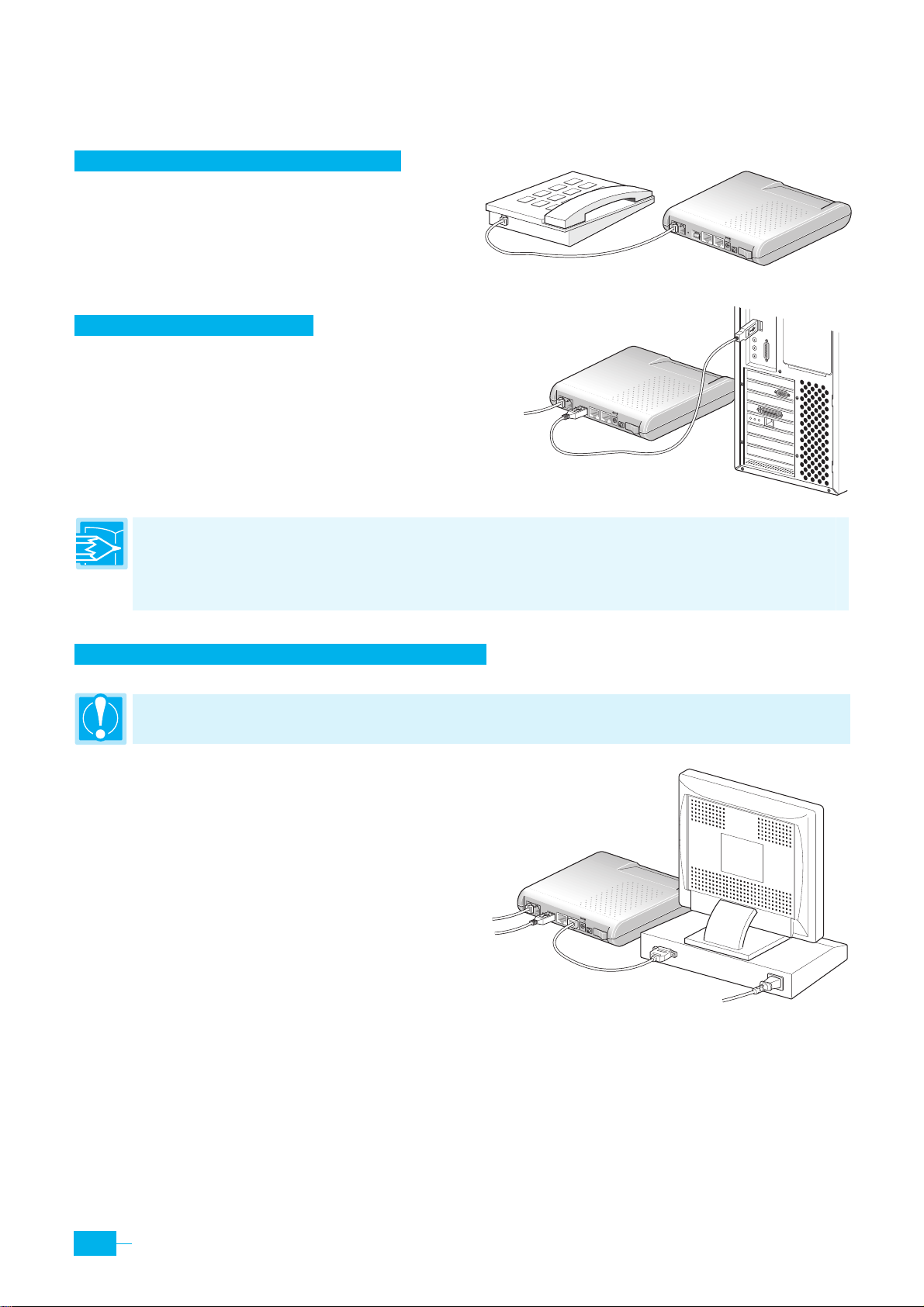
Optional Procedure of Cabling
Connecting Telephone (PHONE Port)
Connect the telephone line to the
PHONE port of the
Corecess 3115 and a telephone.
<위 그림에서 LINE 포트에 케이블이 연결되어 있게 해주세요.>
Connecting PC (USB Port)
If you use the USB port, connect the provided USB
cable to the
connect the other end of the cable to
USB port of the Corecess 3115 and then
USB port on your
PC.
<위 그림에서 LINE 포트에 케이블이 연결되어 있게 해주세요.>
Note: You can attach a single computer to the device using a USB cable. The USB port is useful if you
have a USB-enabled PC that does not have a network interface card for attaching to your Ethernet
network. For using the USB, you must install a USB driver and configure the computer. For complete
instructions, see page 17.
PHONE
PHONE
LINE
USB
LAN
CONSOL
5V DC
OFF
ON
LINE
USB
LAN
CONSOL
5V DC
OFF
ON
Connecting Console Terminal (CONSOLE Port)
Caution: General users need not to connect a console terminal. It is only for the ADSL Service Provider.
Connect a console cable to the
CONSOL port of the
Corecess 3115 and then connect the other end of the
cable to the terminal or a PC.
PHONE
LI
NE
USB
L
A
N
CON
SOL
5V D
C
<위 그림에서 LINE 포트에 케이블이 연결되어 있게 해주세요.>
OFF
ON
12
Corecess 3115 Installation Guide
Page 12
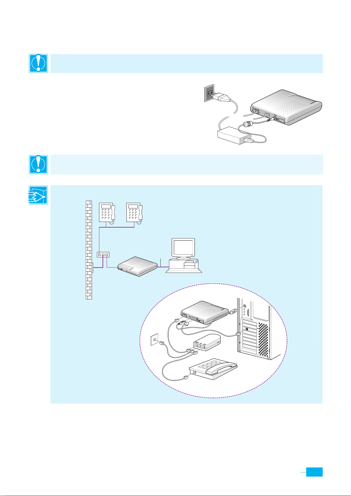
Connecting Power
Caution: You must use the power adapter provided with the Corecess 3115.
n Connect the provided power supply cable into the
5V DC port of the Corecess 3115.
o Connect the provided power cord to the power
supply and connect the other end of the cord to an
appropriate electrical outlet.
Caution: You must power on the Corecess 3115 before powering on your PC. If you power on your PC
first, PC’s IP address may not be properly assigned.
Note: The following figure shows a configuration using a POTS splitter instead of micro-filters.
Voice
Splitter
Data
WR
P
LINK
T
NE
CT
A
N
A
L
TA
DA
C
o
r
ece
ss311
5
Corecess 3115
Ethernet
or
USB
PC
o
PHONE
LINE
LAN
5V DC
OFF
ON
n
<3115 뒷면에서 PHONE 포트를
삭제해주세요.>
Corecess 3115
PHONE
LI
NE
USB
C
ON
S
O
L
LA
N
5V D
C
Data
Voice
O
FF
ON
USB
Ethernet
PC
Splitter
13
Page 13
Configuring Your Computers
This section provides instructions for configuring the Internet settings on your computers to work
with the Corecess 3115.
Before you begin
By default, the Corecess 3115 automatically assigns all required Internet settings to your PCs. You
need only to configure the PCs to accept the information when it is assigned.
y If you have connected your PC via the USB port, see the USB configuration instructions on page 17.
y If you have connected your PC of LAN via the LAN port to the Corecess 3115, follow the
instructions that correspond to the operating system installed on your PC.
Caution: When you configure your computer, leave the default value of any other configuration that
is not mentioned in the following description.
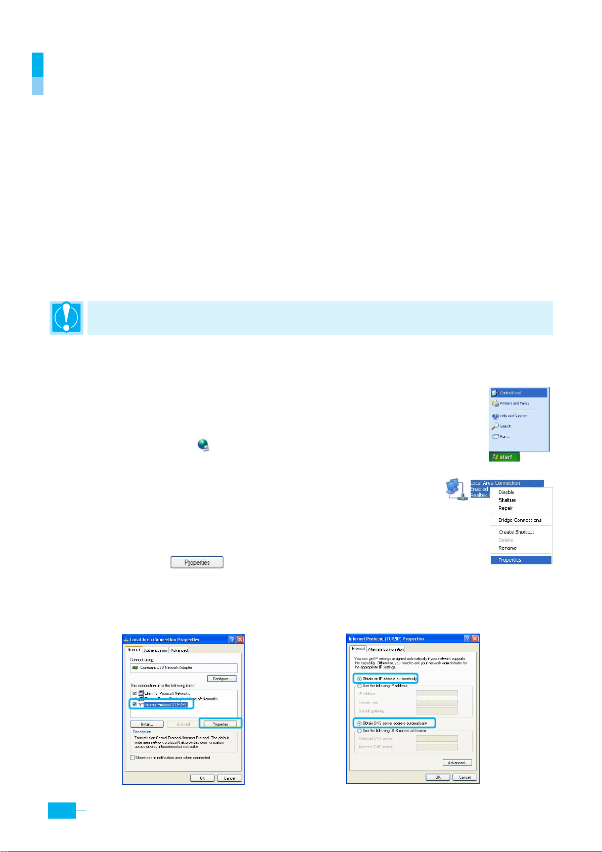
Windows XP
1. In the Windows task bar, click the Start button and then select
Control Panel. (Figure 1)
2.
Double-click the
3. Right-click the
Connections> windows and select
4.
In the <Local Area Connection Properties> dialog box, select the
Internet Protocol (TCP/IP)
items’ list and click
5. In the <Internet Protocol (TCP/IP) Properties)> dialog box, click the radio button labeled
Network
Local Area Connection icon at the <Network
icon at the <Control Panel> window.
Properties. (Figure 2)
in the ‘This connection uses the following
(Figure 3)
.
Figure 1
Figure 2
Obtain an IP
address automatically.
14
Corecess 3115 Installation Guide
Also click the radio button labeled the Obtain DNS server address automatically. (Figure 4)
Figure 3
Figure 4
Page 14
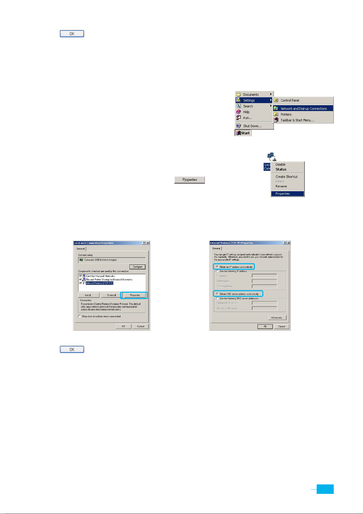
6. Click twice to confirm your changes, and close the Control Panel.
Windows 2000/NT
1. In the Windows task, click the Start button, point to Settings,
and then click
Network and Dial-up Connections. (Figure 1)
2. Right-click the
and Dial-up Connections> windows and then select
Properties. (Figure 2)
Local Area Connection icon at the <Network
Figure 1
3.
In the <Local Area Connection Properties> dialog box,
select
(Figure 3)
Internet Protocol (TCP/IP )
, and then click .
Figure 2
4. In the <Internet Protocol (TCP/IP) Properties> dialog box, click the radio button labeled
an IP address automatically
(Figure 4)
. Also click the radio button labeled Obtain DNS server address automatically.
Obtain
5.
Click
Figure 3
twice to confirm your changes, and close the Control Panel.
Figure 4
15
Page 15
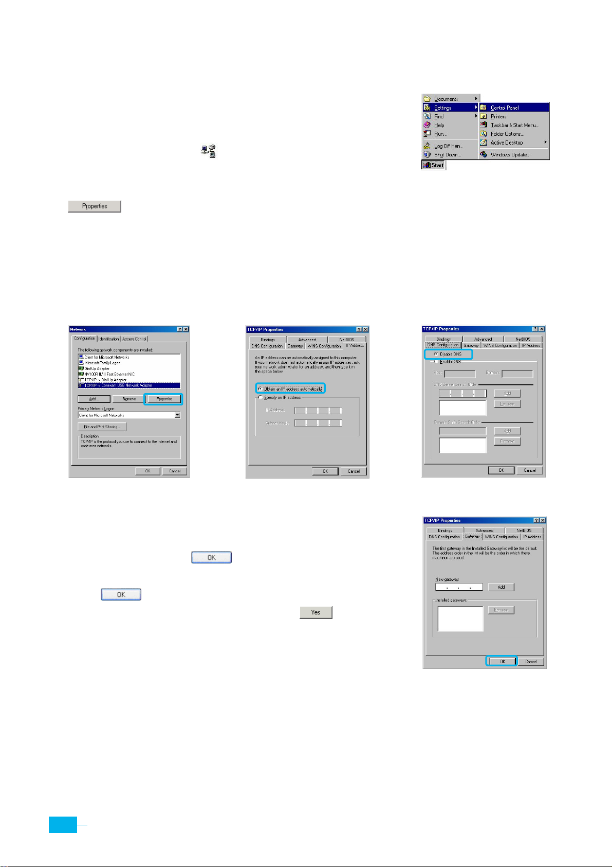
Windows 95/98/ME
1. In the Windows task bar, click the Start button, point to Settings,
and then click
Control Panel. (Figure 1)
2.
Double-click the
3.
In the <Network> dialog box, select
.
Network
(Figure 2)
icon.
TCP/IP
, and then click
Figure 1
In the <TCP/IP Properties> dialog box, click the [IP Address] tab and then click the radio button
4.
labeled
Obtain an IP address automatically. (Figure 3)
5. Click the
[DNS Configuration] tab, and then click the radio button labeled Disable DNS. (Figure 4)
Figure 2 Figure 3
6.
Click the
[Gateway]
tab and ensure that there is no gateway
installed. If there are installed gateways, delete them by
clicking
[Remove]
. Click
(Figure 5)
.
7.
Click
twice to confirm and save your changes. You
will be prompted to restart Windows. Click
Figure 4
.
Figure 5
16
Corecess 3115 Installation Guide
Page 16
Configuring a Computer Connected to the USB Port
If you use the Corecess 3115’s USB port to connect to a PC, you must install the provided USB
driver software on the PC. The driver enables Ethernet-over-USB communication with the
Corecess 3115.
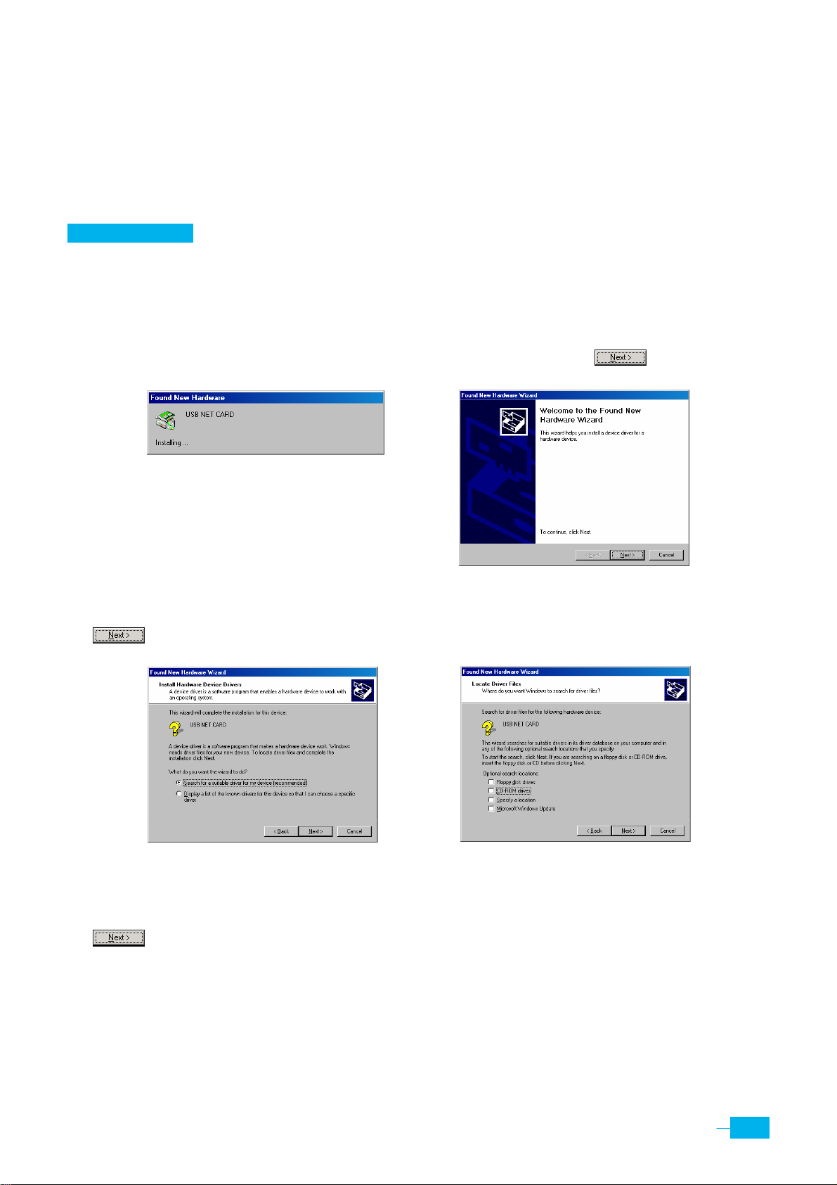
Windows 2000
1. Turn on the PC connected with the Corecess 3115.
2.
Once the Corecess 3115 is connected to the PC, the Windows plug-and-play routine will detect
the new device and show the <Found New Hardware Wizard>. Click .
(Figure 1, 2)
Figure 1
Figure 2
3.
Two choices appear. Choose
to go to the next wizard panel.
Search f or a suitable driver for my de v ice (recommend ed)
(Figure 3)
and click
Figure 3 Figure 4
4.
The wizard prompts you to specify a location to search for the driver you are installing. After
inserting the installation driver CD into the CD-ROM drive, click
(Figure 4)
.
CD-ROM d ri v es
and click
17
Page 17
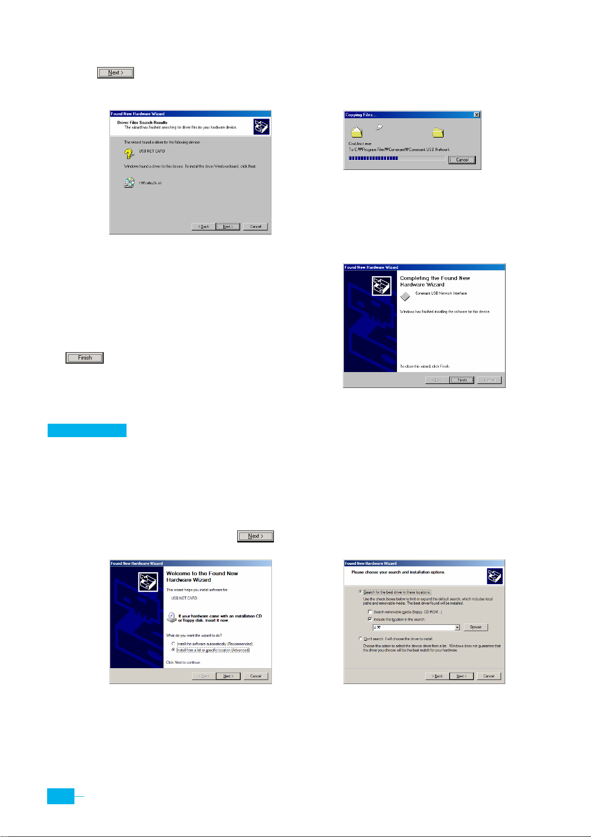
5.
The wizard shows a verification panel and displays the choice you made(USB NET CARD).
Click
the USB.
to start the installation of the drivers and connection to the ADSL modem over
(Figure 5)
Figure 5
6.
The system finds the driver and begins to
automatically copy the driver files from the CD.
(Figure 6)
7.
When the driver installation is complete, click
(Figure 7)
.
Figure 6
Figure 7
Windows XP
1. Turn on the PC connected with the Corecess 3115.
2.
Once the Corecess 3115 is connected to the PC, the Windows plug-and-play routine will detect
the new device and show the <Found New Hardware Wizard>. Choose
specific location (Advanced)
and click to go to the next wizard panel.
Install from a list or
(Figure 1)
18
Figure 1
Corecess 3115 Installation Guide
Figure 2
Page 18
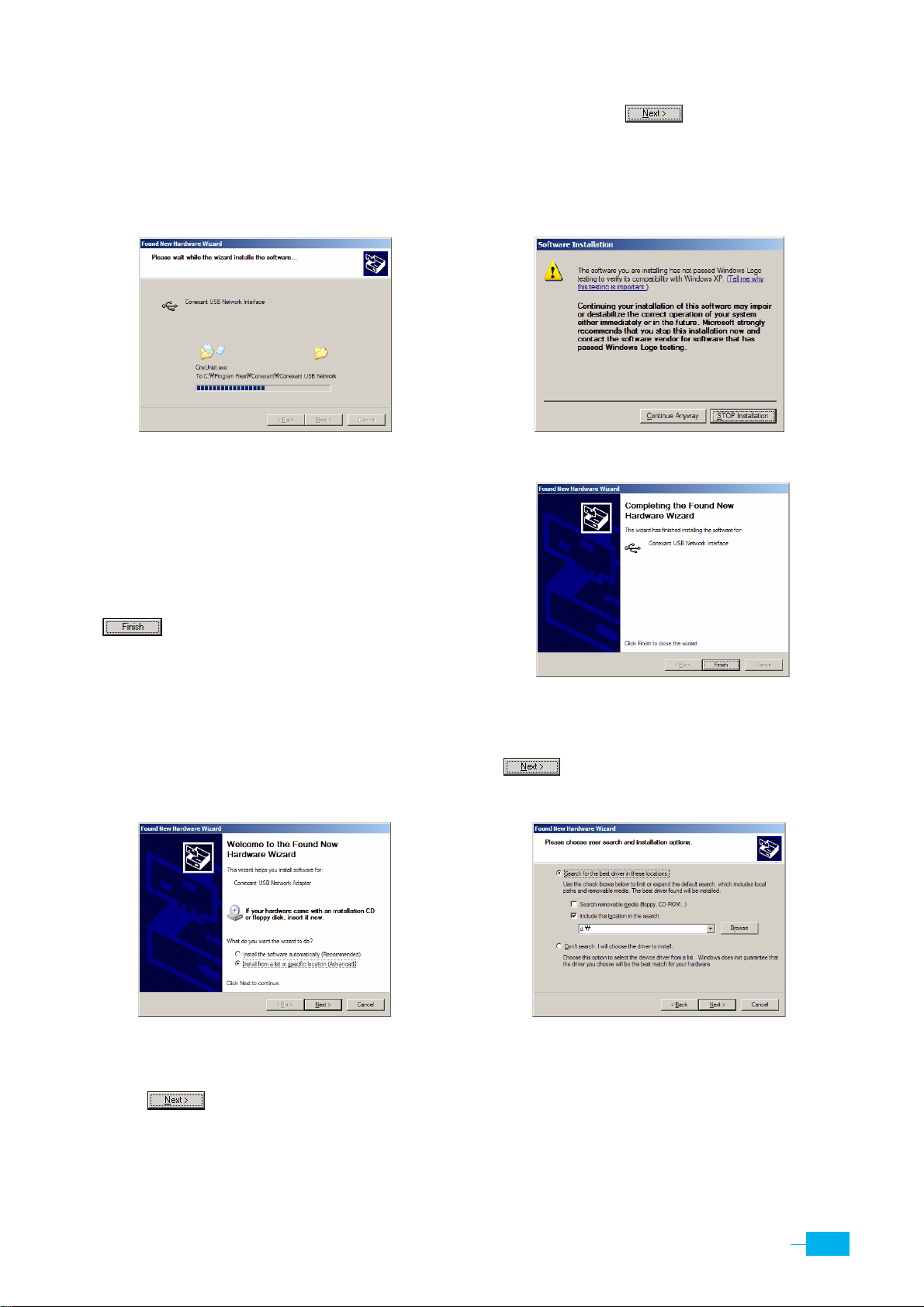
3.
Two choices appear. Choose
Insert the installation driver CD into the CD-ROM drive and click
Include this location in the search
and enter the CD-ROM drive letter.
(Figure 2)
.
4. If the path is correct, the system finds the driver and begins to automatically copy the driver
files from the CD.
(Figure 3)
Figure 3
Figure 4
5. During the driver installation, the window for
verifying the compatibility of the driver with XP
may appear. Click
Continue Anyway. (Figure 4)
6.
When the driver installation is complete, click
(Figure 5)
.
Figure 5
7.
The <Found New Hardware Wizard> appears again to install USB Network Adapter. Choose
Install from a list or specific location (Advanced)
(Figure 6)
and click to go to the next wizard panel.
Figure 6
8.
Two choices appear. Choose
click
(Figure 7)
.
Include this location in the search
Figure 7
, enter the CD-ROM drive letter and
19
Page 19
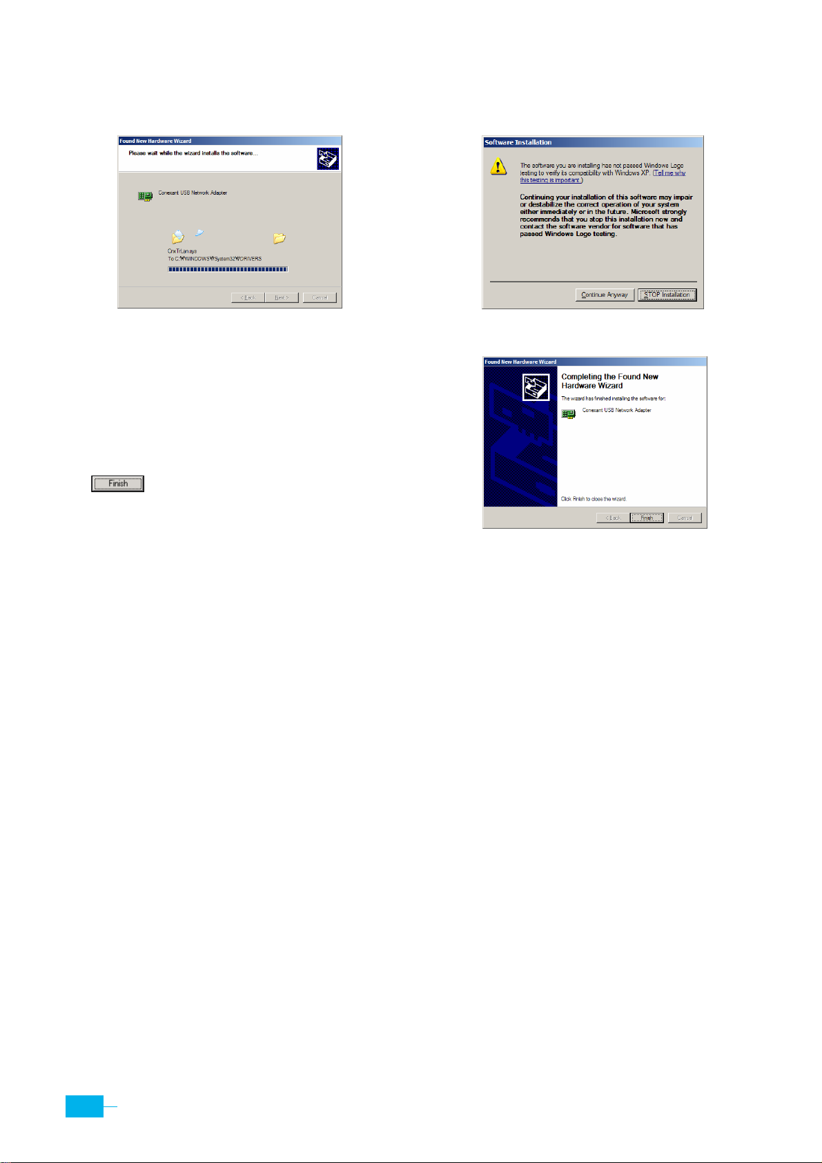
9. The system finds the driver and begins to automatically copy the driver files from the CD.
(Figure 8)
Figure 8
10. During the driver installation, the window for
verifying the compatibility of the driver with XP
may appear. Click
Continue Anyway. (Figure 9)
11.
When the driver installation is complete, click
(Figure 10)
.
Figure 9
Figure 10
12.
Now that the USB driver installation is complete, you must configure the USB PC so
that its IP properties place it on the same subnet as the Corecess 3115’s USB port. The
Corecess 3115 is configured to assign an appropriate IP address to the USB PC. If you
want to use this automatic assignment feature, called ‘DHCP server’, you must
configure the USB PC to accept dynamically assigned IP information. Follow the
instruction on pages 14 through 16 that correspond to the operating system installed on
the PC.
20
Corecess 3115 Installation Guide
Page 20
Troubleshooting
If you cannot connect to ADSL network, please check the status of the LEDs on the front panel,
and then ensure the following:
1.
Check the LAN LED
If the LAN LED goes off, ensure that the Ethernet cable is firmly connected both to the LAN
port on the Corecess 3115 and Ethernet port on the NIC installed to your PC.
2. Check the LINK LED
If the LINK LED blinks continuously and never stays solid on, ensure that the ADSL cable is
firmly connected to the LINE port on the Corecess 3115. If the LINK LED still blinks, contact
your ADSL service provider. If the LINK LED goes off, turn off the power of the Corecess 3115
by pressing the power switch and turn on the power again. If LINK LED still blinks, contact
your vendor.
3. Check your PC’s IP address
If all LEDs operate normally and cables are firmly connected to the ports, ensure that your
PC’s IP address is properly assigned. Otherwise, assign a new IP address according to your
operating system.
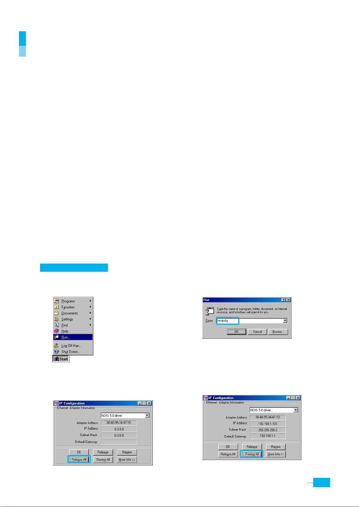
Windows 95/98/ME
n Click the
Start button and select Run.
o Input
winipcfg and press the [Enter] key.
p Select Ethernet adapter connected with
the Corecess 3115 and click
Release All.
q
Click Renew All.
21
Page 21
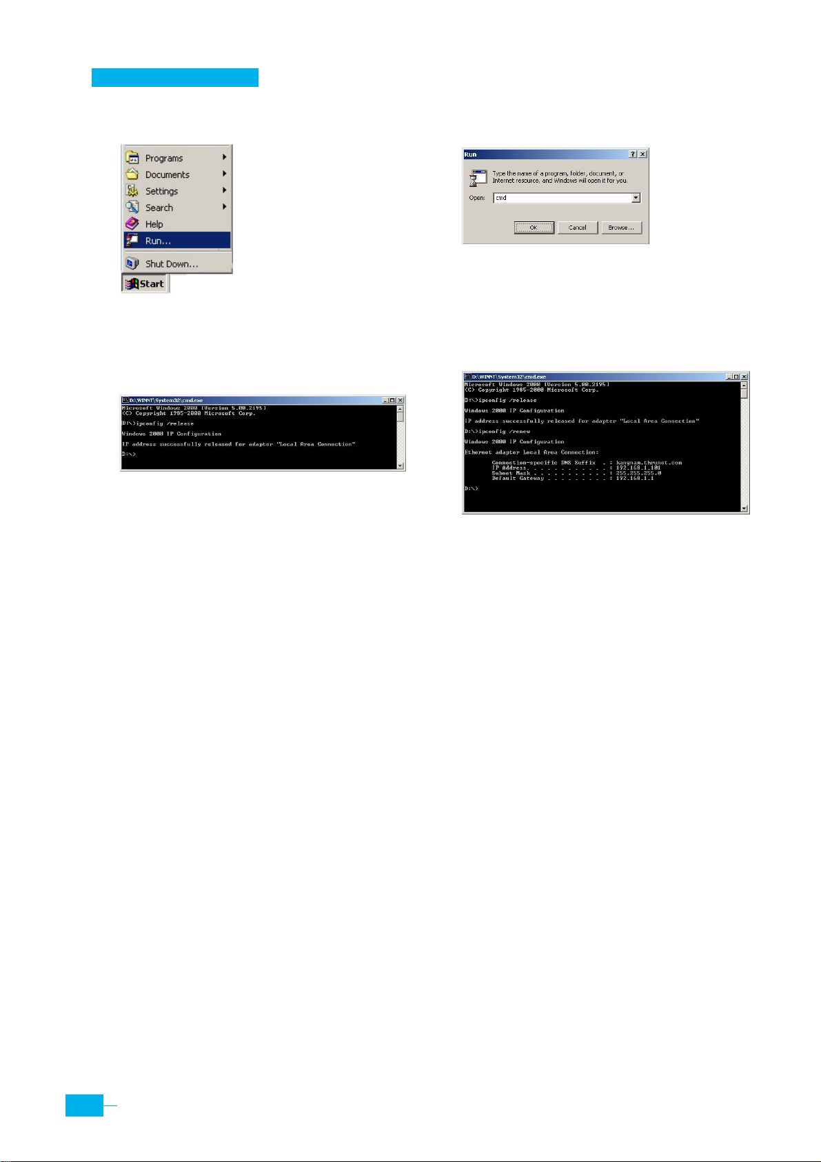
Windows 2000/NT/XP
n Click the
Start button and select Run.
p The DOS-prompt appears. Input
/release
and press [Enter] key.
ipconfig
o
Input cmd and press the [Enter] key.
q Input
ipconfig /renew and press [Enter] key.
4. Restart your PC
If new IP address is not assigned properly or you cannot solve the problem, ensure that the
Corecess 3115 turns on and then restart your PC.
22
Corecess 3115 Installation Guide
Page 22
Technical Specifications
Description Specification
ADSL Standard
y T1.413i2 ADSL Standard
y ITU-T G.992.1(G.dmt) ADSL Standard
Standard
y ITU-T G.992.2(G.lite) ADSL Standard
IEEE Standard
y IEEE 802.3 10Base-T
y IEEE 802.3u 100Base-TX
Ethernet
y 10/100Base-TX
y Connector: RJ-45, USB
Interface
ADSL Protocol
Connector
Default
Option
ADSL Line
y Line Code : DMT (Discrete Multi-Tone)
y Downstream : Max 8Mbps
y Upstream : Max 1Mbps
y Connector : RJ-11
y PPP over ATM VCMUX (RFC 2364)
y PPP over ATM LLCSNAP (RFC 2364)
y Bridged IP over ATM LLCSNAP (RFC 1483)
y Routed IP over ATM LLCSNAP (RFC 1483)
y Bridged IP over ATM VCMUX (RFC 1483)
y Routed IP over ATM VCMUX (RFC 1483)
y Classical IP over ATM (RFC 1577)
y PPP over Ethernet VCMUX (RFC 2516)
y PPP over Ethernet LLCSNAP (RFC 2516)
y 1 RJ-11 (LINE)
y 1 RJ-45 (LAN)
y 1 Power socket (DCIN)
y 1 RJ-11 (PHONE)
y 1 USB (USB)
y 1 RJ-45 (CONSOLE)
y 1 Power socket (DCIN)
LED
Environmental
Conditions
Physical Conditions
y PWR : Indicates DC power status
y LINK : Indicates connection status with ADSL network (physical link)
y NET : Indicates connection status with WAN
y ACT : Indicates the ADSL data activity
y LAN : Indicates connection status with PC
y DATA : Indicates the LAN data activity
y Temperature : 0°C ~ 50°C
y Humidity : 5% ~ 90%
y Dimension : 140(W) x 150(D) x 30(H) mm
y Weight : 250g
23
Page 23

Power Requirements
y Input: 100-240VAC, 50-60Hz, DC 9V/1A
y Power consumption: Max. 4Watt
24
Corecess 3115 Installation Guide
Page 24

25
 Loading...