

I
MANUALE D’USO - TERMOACCUMULATORI 1
GB
F
DE
E
PL
GR
RO
HU
RU
USER MANUAL - Multi Fuel Energy Cylinders 6
NOTICE D’EMPLOI - Ballons Primaire 11
BEDIENUNGSHANDBUCH - Pufferspeicher 16
INSTRUCCIONES DE USO -Termo-Acumuladores 21
INSTRUKCJA OBSŁUG - Zbiorniki Buforowe 26
ΟΔΗΓΙΕΣ ΧΡΗΣΗΣ - Συνδυασμενοι Θερμοσυσσωρευτες 31
INSTRUCŢIUNI DE FOLOSIRE - Termoccumulatori 36
HASZNÁLATI UTASÍTÁS - HŐTÁROLÓK 41
ИНСТРУКЦИИ ПО ЭКСПЛУАТАЦИИ - Тепловые Аккумуляторы 46
CZ
LT
SK
SLO
NÁVOD K POUŽITÍ - Zásobníky Teplé Vody 51
NAUDOJIMO INSTRUKCIJOS - Termoakumuliacinės Talpos 56
NÁVOD NA POUŽITIE - Kombinované Tepelné Akumulátore 61
NAVODILA ZA UPORABO - Termoakumulatorji 66
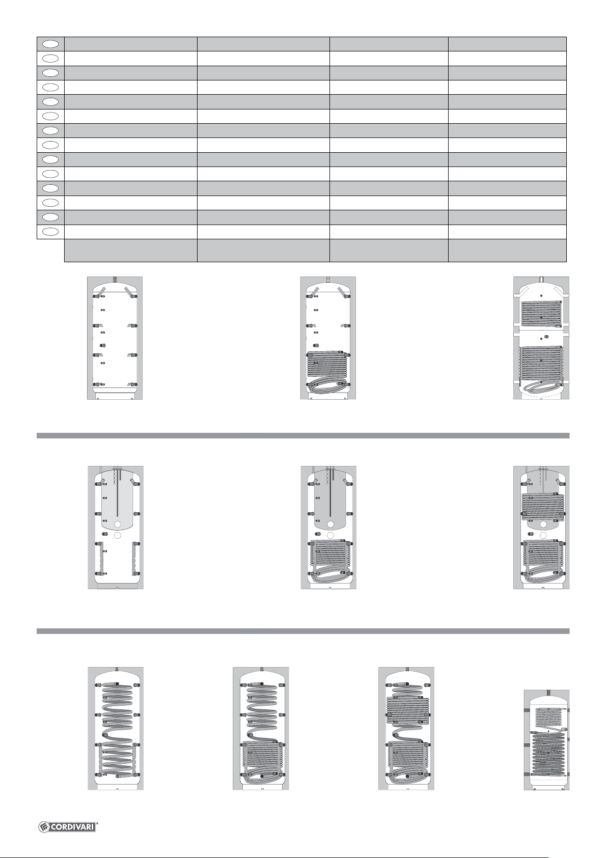
PUFFER VC VT
PUFFER 1 VC VT
PUFFER 2 VC VT
V2
V1
V2
V1
COMBI 1-2-3
V2
V1
ECO-COMBI 1-2-3
ECO-COMBI “DOMUS”
CORDIVARI S.r.l. Z. I. Pagliare - I-64020 Morro D’Oro (TE) - Italy • Cap. Soc. € 4.000.000,00 i.v. - C. F./P. IVA - Reg. Impr. TE 00735570673 - R.E.A. TE n. 92310
Tel : +39 085 80.40.1 - Fax : +39 085 80.41.418 • www.cordivari.it - info@cordivari.it • UNI EN ISO 9001:2008 - UNI EN ISO 14001:2004
I
Pressione massima accumulo Pressione massima scambiatore Temperatura massima accumulo Temperatura massima scambiatore/i
GB
Max Pressure Storage Max Pressure Exchanger Max Temperature Storage Max Temperature Exchanger
F
P Max Accumulation P Max Echangeur T Max Accumulation T Max Echangeur
D
P Max Speicher P Max Warmetauscher T Max Speicher T Max Warmetauscher
E
Presión máxima de acumulación Presión máxima intercambiador T Max acumulación P Max intercambiador
PL
Maksymalne ciśnienie w zbiorniku buforowym Maksymalne ciśnienie w wymienniku T Max w zbiorniku buforowym C Max w wymienniku
GR
Μέγιστη πίεση αποθέματος Μέγιστη πίεση εναλλάκτη Μέγ. Θ. αποθέματος Μέγ. Π. εναλλάκτη
RO
Presiune maximă acumulare Presiune maximă schimbător T Max acumulare P Max schimbător
HU
Maximális töltési nyomás Maximális hőcserenyomás T Max töltési nyomás P Max hőcserenyomás
RU
Максим. давление накопления Максим. давление теплообменника T Max накопления P Max теплообменника
CZ
Maximální tlak zásobníku Maximální tlak výměníku T Max zásobníku P Max výměníku
LT
Didžiausias kaupimo slėgis Didžiausias šilumokaičio slėgis Didžiausia temperatūra Didžiausias slėgis
SK
Maximálny nárast tlaku Maximálny tlak výmenníka T Max nárast P Max výmenníka
SLO
Maksimalni akumulacijski pritisk Maksimalni pritisk izmenjalnika T Max akumulacijski P Max izmenjalnika
3 bar 12 bar 99 °C 110 °C
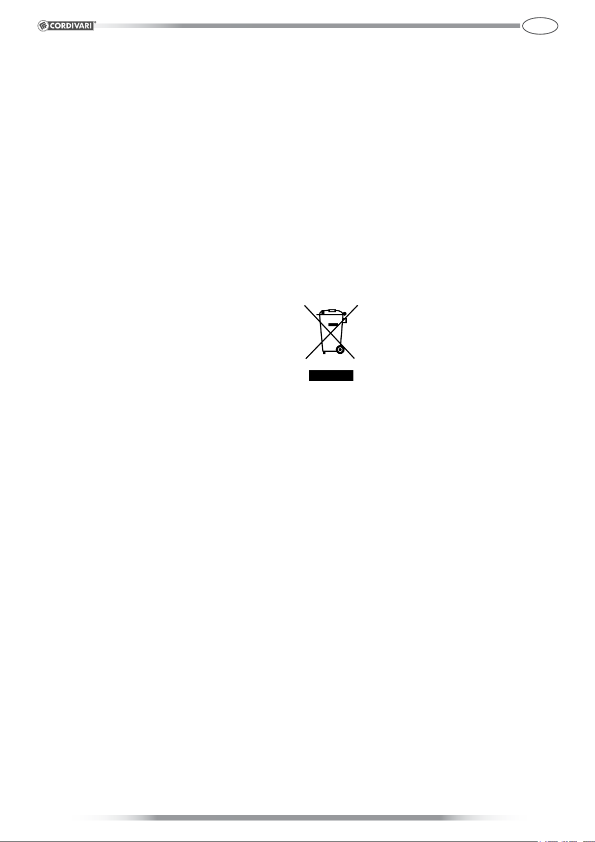
PUFFER
COMBI PUFFER
COMBI 1
PUFFER 1
V2
V1
V2
V1
COMBI 2
PUFFER 2
V2
V1
COMBI 3
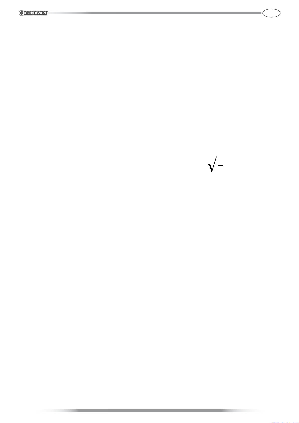
ECO-COMBI
ECO-COMBI 1
ECO-COMBI 2
ECO-COMBI 3 ECO-COMBI 2
DOMUS
Generalità e destinazione d’uso - PUFFER
Il presente documento è destinato all’installatore ed all’utilizzatore
fi nale. Pertanto dopo l’istallazione e l’avvio dell’impianto occorre
assicurarsi che esso sia consegnato all’utilizzatore fi nale o al
responsabile della gestione dell’impianto.
I Termoaccumulatori PUFFER VC VT, PUFFER 1 VC VT e PUFFER
2 VC VT costruiti dalla Cordivari S.r.l. sono stati progettati per
l’impiego in quegli impianti di riscaldamento speciali pensati
per sfruttare una sorgente termica a funzionamento tipicamente
discontinuo. Infatti grazie alla loro capacità di immagazzinare
calore trovano applicazione negli impianti di riscaldamento
funzionanti con caldaie a combustibile solido, pompe di calore
e impianti solari.
In particolare l’installazione di un Puff er abbinato con un
generatore a combustibile solido determina i seguenti vantaggi:
• Consente al generatore di funzionare in modo regolare,
evitando interruzioni dovute a insuffi ciente richiesta di energia
da parte dell’impianto di riscaldamento: in queste condizioni,
invece di bloccare la combustione o surriscaldare gli ambienti, il
generatore può continuare a funzionare immagazzinando energia
nel serbatoio di accumulo. Questa energia si renderà disponibile
successivamente quando il progressivo esaurimento del
combustibile determinerà una riduzione della potenza erogata
dalla caldaia. Il funzionamento senza interruzioni riduce la
fumosità delle emissioni e lo sporcamento del camino, protegge
la caldaia da dannose formazioni di condensati catramosi, e
aumenta il rendimento globale dell’impianto.
• Costituisce un “volano termico” per l’impianto di riscaldamento
e fa aumentare grandemente il comfort di esercizio, rendendolo
del tutto simile a quello di impianti automatici a gas/gasolio.
Infatti, l’energia contenuta nell’accumulatore sotto forma di
acqua calda viene automaticamente ceduta all’impianto nel
momento in cui questo la richiede. Questo assicura alcune ore di
riscaldamento anche a caldaia spenta, ad esempio nelle prime
ore del mattino.
I
trasporto. Per questo scopo i recipienti vanno movimentati
esclusivamente a vuoto.
Prevedere un sistema adeguato di espansione, calcolato
tenendo conto, oltre al volume dell’impianto, anche del volume
del termoaccumulatore.
L’installazione e l’esercizio dell’apparecchio oggetto delle
presenti istruzioni deve sempre rispettare le norme ed i
regolamenti nazionali e locali del luogo di installazione.
Se l’impianto supera i valori ammissibili di pressione installare
un riduttore di pressione il più lontano possibile dal bollitore
stesso.
4. Connessioni
Ogni termoaccumulatore riporta su un’apposita etichetta la
generica destinazione d’uso delle connessioni previste. In caso
è fatto carico al progettista dell’impianto su cui verrà installato
l’apparecchio valutare, nel rispetto delle norme di installazione
vigenti, lo schema impiantistico migliore per il suo utilizzo in
osservanza dei limiti (di pressione e temperatura) dichiarati dal
costruttore.
5. Smaltimento
Alla fi ne del ciclo di vita tecnico del prodotto i suoi
componenti metallici vanno ceduti ad operatori
autorizzati alla raccolta dei materiali metallici
fi nalizzata al riciclaggio mentre i componenti
non metallici vanno ceduti ad operatori
autorizzati al loro smaltimento. I prodotti devono
essere gestiti, se smaltiti dal cliente fi nale, come
assimilabili agli urbani pertanto nel rispetto dei
regolamenti del comune di appartenenza. In ogni caso esso non
va gestito come un rifi uto domestico
Pertanto, i termoaccumulatori Puff er sono destinati a contenere
solo acqua (cosiddetta “tecnica”) di impianti di riscaldamento
a circuito chiuso. Ogni utilizzo del prodotto diverso da quello
indicato nel presente documento solleva il costruttore da ogni
responsabilità e comporta il decadimento di ogni forma di
garanzia.
Le versioni che prevedono la presenza di uno più scambiatori
consentono di sfruttare l’energia termica generata da un
impianto solare ed in generale per separare idraulicamente più
sorgenti termiche.
2. Identifi cazione della categoria ( Direttiva 97/23/CE)
Ai sensi della Direttiva 97/23/CE i termoaccumulatori oggetto del
presente rientrano in quanto previsto nell’ Art. 3.3 della Direttiva
stessa. Pertanto non necessitano di marcatura CE, tuttavia la
Cordivari S.r.l. garantisce per essi, come stabilito dalla Direttiva
, una corretta prassi costruttiva (assicurata dal Sistema Qualità
aziendale ISO 9001 ) che ne assicura la sicurezza di utilizzazione
e la individuazione del costruttore.
3. Installazione e Manutenzione
I Termoaccumulatori vanno sempre installati al riparo dagli agenti
atmosferici, su basamento di adeguata solidità , verifi cando,
prima di eff ettuare i collegamenti, che vi sia spazio suffi ciente per
l’estrazione dei dispositivi direttamente collegati al recipiente.
La fase di movimentazione degli apparecchi il cui peso ecceda
i 30 kg richiede l’ausilio di idonei mezzi di sollevamento e
BS_100_Rev_1
CORDIVARI - 1
Generalità e destinazione d’uso - COMBI
Il presente documento è destinato all’installatore ed all’utilizzatore
fi nale. Pertanto dopo l’istallazione e l’avvio dell’impianto occorre
assicurarsi che esso sia consegnato all’utilizzatore fi nale o al
responsabile della gestione dell’impianto.
I Termoaccumulatori Combinati COMBI 1, 2, 3 XC/WC VT
costruiti dalla Cordivari S.r.l. sono stati progettati per l’impiego
in quegli impianti di riscaldamento e contemporanea produzione
di acqua calda sanitaria alimentati da un o più sorgenti termiche
a funzionamento tipicamente discontinuo. Infatti grazie alla loro
capacità di immagazzinare calore trovano applicazione negli
impianti di riscaldamento funzionanti con caldaie a combustibile
solido, pompe di calore e impianti solari.
I termoaccumulatori Combi sono sempre costituiti da due
camere delle quali la principale funge da vero e proprio
termoaccumulatore mentre la secondaria (contenuta nella prima)
funge da preparatore di acqua calda sanitaria ad accumulo. Le
versioni Combi 2 e Combi 3 presentano inoltre 1 e 2 scambiatori
a serpentino elicoidale e consentono di sfruttare l’energia termica
generata da un impianto solare ed in generale per separare
idraulicamente più sorgenti termiche.
Il volume principale del Combi connesso ad un generatore a
combustibile solido determina i seguenti vantaggi:
• Consente al generatore di funzionare in modo regolare,
evitando interruzioni dovute a insuffi ciente richiesta di energia
da parte dell’impianto di riscaldamento: in queste condizioni,
invece di bloccare la combustione o surriscaldare gli ambienti,
il generatore può continuare a funzionare immagazzinando
energia nel serbatoio di accumulo. Questa energia si renderà
disponibile successivamente quando il progressivo esaurimento
del combustibile determinerà una riduzione della potenza erogata
dalla caldaia. Il funzionamento senza interruzioni riduce la
fumosità delle emissioni e lo sporcamento del camino, protegge
la caldaia da dannose formazioni di condensati catramosi, e
aumenta il rendimento globale dell’impianto.
• Costituisce un “volano termico” per l’impianto di riscaldamento
e fa aumentare notevolmente il comfort di esercizio, rendendolo
del tutto simile a quello di impianti automatici a gas/gasolio. Infatti,
l’energia contenuta nell’accumulatore sotto forma di acqua calda
viene automaticamente ceduta all’impianto nel momento in cui
questo la richiede. Questo assicura alcune ore di riscaldamento
anche a caldaia spenta, ad esempio nelle prime ore del mattino.
Pertanto, il volume principale dei termoaccumulatori Combi
è destinata a contenere solo acqua (cosiddetta “tecnica”) di
impianti di riscaldamento a circuito chiuso.
Il volume secondario è invece pensato per contenere acqua
sanitaria che si riscalda per il fatto che il volume secondario è
“immerso” nel volume principale.
Ogni utilizzo del prodotto diverso da quello indicato nel presente
documento solleva il costruttore da ogni responsabilità e
comporta il decadimento di ogni forma di garanzia.
2. Identifi cazione della categoria ( Direttiva 97/23/CE)
Ai sensi della Direttiva 97/23/CE i termoaccumulatori oggetto del
presente rientrano in quanto previsto nell’ Art. 3.3 della Direttiva
stessa. Pertanto non necessitano di marcatura CE, tuttavia la
Cordivari S.r.l. garantisce per essi, come stabilito dalla Direttiva
, una corretta prassi costruttiva (assicurata dal Sistema Qualità
aziendale ISO 9001 ) che ne assicura la sicurezza di utilizzazione
e la individuazione del costruttore.
3. Installazione e Manutenzione
I Termoaccumulatori vanno sempre installati al riparo dagli agenti
atmosferici, su basamento di adeguata solidità,verifi cando,
prima di effettuare collegamenti, che vi sia spazio suffi ciente
per l’estrazione dello scambiatore, dell’anodo di magnesio,
dell’eventuale resistenza.
Verifi care che i locali destinati all’ubicazione degli apparecchi
abbiano aperture di dimensioni tali da consentire il libero
passaggio degli stessi verso l’esterno senza che vi sia la
necessità di operare demolizioni di alcun genere.
I
Assicurarsi che il locale di installazione del bollitore sia dotato
di un sistema di drenaggio (scarico) adeguato al volume del
bollitore e di altri eventuali apparecchi. La garanzia non copre
eventuali costi derivanti da inadempienze al presente punto.
La fase di movimentazione degli apparecchi il cui peso ecceda i
30kg richiede l’ausilio di idonei mezzi di sollevamento e trasporto.
Per questo scopo i recipienti vanno movimentati esclusivamente
a vuoto, per mezzo delle apposite pedane.
Verifi care in sede di installazione la presenza di anodi di
magnesio.
Sulla base di quanto dettato dalla Circolare Ministeriale n.
829571 del 23/03/03 l’istallazione alla rete idrica domestica dei
bollitori deve avvenire tramite un gruppo di sicurezza idraulica,
comprendente almeno un rubinetto di intercettazione, una
valvola di ritegno, un dispositivo di controllo della valvola di
ritegno, una valvola di sicurezza, un dispositivo di interruzione
di carico idraulico, tutti accessori necessari ai fi ni dell’esercizio in
sicurezza dei bollitori medesimi.
Prevedere un sistema di espansione. In base a quanto previsto
dalla raccolta R fasc.R-1A per i riscaldatori d’acqua in cui
la temperatura del primario è inferiore o uguale a quella di
ebollizione del fl uido secondario a pressione di 0.5 bar, tale
sistema di espansione può essere costituito semplicemente
da una valvola di sfogo, del tipo a contrappeso o a molla, il cui
orifi zio abbia un diametro in millimetri non inferiore a:
V
5
essendo V il volume in litri del bollitore, con un minimo di 15 mm.
La valvola dovrà essere tarata ad una pressione non superiore
a quella massima di esercizio del bollitore. Oltre alla valvola
è tuttavia consigliabile, come già detto, installare un vaso di
espansione del tipo chiuso a membrana atossica anche per
evitarne continue aperture della valvola di sicurezza.
Se l’impianto dell’acqua sanitaria supera i valori ammissibili di
pressione del bollitore installare un riduttore di pressione il più
lontano possibile dal bollitore stesso.
Programmare inizialmente dei controlli frequenti dell’anodo di
magnesio questo perché il suo consumo non si può stabilire a
priori in quanto dipende dalle condizioni operative e dalla natura
dell’acqua.
In generale negli impianti di produzione di acqua calda sanitaria
ci si deve attenere a quanto disposto dalla norma UNI CTI 8065
che prevede vari tipi di trattamenti dell’acqua in funzione delle
sue caratteristiche. La garanzia non copre danni derivanti da
inadempienze alle prescrizioni della norma UNI CTI 8065.
Si ricorda che gli apparecchi vanno sempre elettricamente
collegati a terra.
4. Connessioni
Ogni termoaccumulatore riporta su un’apposita etichetta la
generica destinazione d’uso delle connessioni previste. In caso
è fatto carico al progettista dell’impianto su cui verrà installato
l’apparecchio valutare, nel rispetto delle norme di installazione
vigenti, lo schema impiantistico migliore per il suo utilizzo in
osservanza dei limiti (di pressione e temperatura) dichiarati dal
costruttore.
5. Condizioni operative
Rispettare i valori limite di pressione e temperatura indicati sulla
targa dati dell’apparecchio.
Attenzione!
Prevedere sempre il riempimento del volume del bollitore (lato
acqua sanitaria) prima di quello del termoaccumulatore (lato
acqua di riscaldamento). In esercizio evitare assolutamente
che la pressione del termoaccumulatore ecceda quella del
bollitore per più di 1,5 bar
BS_100_Rev_1
CORDIVARI - 2

6. Smaltimento
Alla fi ne del ciclo di vita tecnico del prodotto i suoi componenti
metallici vanno ceduti ad operatori autorizzati alla raccolta
dei materiali metallici fi nalizzata al riciclaggio
mentre i componenti non metallici vanno ceduti
ad operatori autorizzati al loro smaltimento.
I prodotti devono essere gestiti, se smaltiti dal
cliente fi nale, come assimilabili agli urbani
pertanto nel rispetto dei regolamenti del comune
di appartenenza. In ogni caso esso non va
gestito come un rifi uto domestico.
I
BS_100_Rev_1
CORDIVARI - 3
Generalità e destinazione d’uso - ECO COMBI
Il presente documento è destinato all’installatore ed all’utilizzatore
fi nale. Pertanto dopo l’istallazione e l’avvio dell’impianto occorre
assicurarsi che esso sia consegnato all’utilizzatore fi nale o al
responsabile della gestione dell’impianto.
I Termoaccumulatori Combinati ECO COMBI 1, 2, 3 ed ECO-
COMBI 2 DOMUS costruiti dalla Cordivari S.r.l. sono stati
progettati per l’impiego in quegli impianti di riscaldamento e
contemporanea produzione di acqua calda sanitaria alimentati
da un o più sorgenti termiche a funzionamento tipicamente
discontinuo. Infatti grazie alla loro capacità di immagazzinare
calore trovano applicazione negli impianti di riscaldamento
funzionanti con caldaie a combustibile solido, pompe di calore
e impianti solari.
I termoaccumulatori Combi sono sempre costituiti da una camera
principale che funge da accumulo inerziale entro la quale vi è
uno scambiatore costituito da una spirale realizzata in tubo
corrugato in acciaio inossidabile Aisi 316L (1.4404) che funge
da preparatore di acqua calda sanitaria. Nella versione 2 inoltre è
presente uno scambiatore a serpentino elicoidale nella versione
3 ne sono presenti due e consentono di sfruttare l’energia termica
generata da un impianto solare ed in generale per separare
idraulicamente più sorgenti termiche.
Il volume principale del Combi connesso ad un generatore a
combustibile solido determina i seguenti vantaggi:
• Consente al generatore di funzionare in modo regolare,
evitando interruzioni dovute a insuffi ciente richiesta di energia
da parte dell’impianto di riscaldamento: in queste condizioni,
invece di bloccare la combustione o surriscaldare gli ambienti,
il generatore può continuare a funzionare immagazzinando
energia nel serbatoio di accumulo. Questa energia si renderà
disponibile successivamente quando il progressivo esaurimento
del combustibile determinerà una riduzione della potenza erogata
dalla caldaia. Il funzionamento senza interruzioni riduce la
fumosità delle emissioni e lo sporcamento del camino, protegge
la caldaia da dannose formazioni di condensati catramosi, e
aumenta il rendimento globale dell’impianto.
• Costituisce un “volano termico” per l’impianto di riscaldamento
e fa aumentare notevolmente il comfort di esercizio, rendendolo
del tutto simile a quello di impianti automatici a gas/gasolio. Infatti,
l’energia contenuta nell’accumulatore sotto forma di acqua calda
viene automaticamente ceduta all’impianto nel momento in cui
questo la richiede. Questo assicura alcune ore di riscaldamento
anche a caldaia spenta, ad esempio nelle prime ore del mattino.
Pertanto, il volume principale dei termoaccumulatori Eco Combi
è destinata a contenere solo acqua (cosiddetta “tecnica”) di
impianti di riscaldamento a circuito chiuso.
La particolare conformazione dello scambiatore interno in acciaio
inox destinato alla produzione di acqua sanitaria, determina
l’eliminazione di tutte le problematiche connesse con l’accumulo
di acqua calda sanitaria (depositi, stagnazione, formazioni di
colonie batteriche, etc.) ed assicura delle ottime performance
in tema di scambio termico. Infatti, essendo lo scambiatore
interno formato da un condotto continuo di tubo corrugato, ad
ogni prelievo di acqua calda sanitaria viene garantito il ricambio
dell’acqua sanitaria stessa all’interno dello scambiatore con
evidenti vantaggi igienici.
Ogni utilizzo del prodotto diverso da quello indicato nel presente
documento solleva il costruttore da ogni responsabilità e
comporta il decadimento di ogni forma di garanzia.
2. Identifi cazione della categoria ( Direttiva 97/23/CE)
Ai sensi della Direttiva 97/23/CE i termoaccumulatori oggetto del
presente rientrano in quanto previsto nell’ Art. 3.3 della Direttiva
stessa. Pertanto non necessitano di marcatura CE, tuttavia la
Cordivari S.r.l. garantisce per essi, come stabilito dalla Direttiva
, una corretta prassi costruttiva (assicurata dal Sistema Qualità
aziendale ISO 9001 ) che ne assicura la sicurezza di utilizzazione
e la individuazione del costruttore.
I
3. Installazione e Manutenzione
I Termoaccumulatori vanno sempre installati al riparo dagli agenti
atmosferici, su basamento di adeguata solidità, verifi cando,
prima di effettuare i collegamenti, che vi sia spazio suffi ciente
per il controllo dell’apparecchio e per l’estrazione dell’eventuale
resistenza elettrica. L’eventuale pedana in legno, che serve
esclusivamente per il trasporto, va eliminata.
Verifi care che i locali destinati all’ubicazione dei
Termoaccumulatori abbiano aperture di dimensioni tali da
consentire il libero passaggio degli stessi verso l’esterno senza
che vi sia la necessità di operare demolizioni di alcun genere.
La fase di movimentazione degli apparecchi il cui peso ecceda i
30 kg richiede l’ausilio di idonei mezzi di sollevamento e trasporto.
Per questo scopo i recipienti vanno movimentati, esclusivamente
a vuoto, per mezzo delle apposite pedane.
I Termoaccumulatori vanno installati ed eserciti nel rispetto della
legislazione nazionale vigente nel paese di utilizzo.
In Italia, sulla base di quanto dettato dalla Circolare Ministeriale
n. 829571 del 23/03/03 l’installazione alla rete idrica domestica
dei bollitori(in linea di principio i Temoaccumulatori sono dei
bollitori particolari) deve avvenire tramite un gruppo di sicurezza
idraulica, comprendente almeno un rubinetto di intercettazione,
una valvola di ritegno, un dispositivo di controllo della valvola
di ritegno, una valvola di sicurezza (per le cui caratteristiche
si veda il punto successivo), un dispositivo di interruzione di
carico idraulico, tutti accessori necessari ai fi ni dell’esercizio in
sicurezza dei bollitori medesimi.
Prevedere un sistema di espansione. In base a quanto previsto
dalla raccolta R fasc.R-1A per i riscaldatori d’acqua in cui
la temperatura del primario è inferiore o uguale a quella di
ebollizione del fl uido secondario a pressione di 0.5 bar, tale
sistema di espansione può essere costituito semplicemente
da una valvola di sfogo, del tipo a contrappeso o a molla, il cui
orifi zio abbia un diametro in millimetri non inferiore a:
V
5
essendo V il volume in litri del bollitore, con un minimo di 15 mm.
. La valvola dovrà essere tarata ad una pressione non superiore
a quella massima di esercizio del bollitore. Oltre alle valvole è
tuttavia consigliabile, anche per evitarne continue aperture,
installare dei vasi di espansione del tipo chiuso a membrana
atossica avente anche la funzione (sul lato sanitario) di
ammortizzatore dei colpi d’ariete.
Si ricorda che le temperature massime di accumulo e di
distribuzione dell’acqua calda sanitaria sono soggette a limiti di
legge. In Italia far riferimento a quanto prescritto dalla legge 10/91
e dal DPR 412 del 23/08/1993 e sue successive modifi cazioni ed
integrazioni.
Se l’impianto dell’acqua sanitaria supera i valori ammissibili
di pressione installare un riduttore di pressione il più lontano
possibile dal termoaccumulatore.
Al fi ne di evitare gli effetti di eventuali correnti galvaniche vaganti
è necessario prevedere sempre una CORRETTA MESSA A
TERRA degli impianti.
4. Connessioni
Ogni termoaccumulatore riporta su un’apposita etichetta la
generica destinazione d’uso delle connessioni previste. In caso
è fatto carico al progettista dell’impianto su cui verrà installato
l’apparecchio valutare, nel rispetto delle norme di installazione
vigenti, lo schema impiantistico migliore per il suo utilizzo in
osservanza dei limiti (di pressione e temperatura) dichiarati dal
costruttore.
In sede di installazione è vivamente consigliato predisporre sul
circuito sanitario delle connessioni (valvole di intercettazione
circuito sanitario e valvole con porta-tubo con rubinetto) per il
BS_100_Rev_1
CORDIVARI - 4

lavaggio preliminare e periodico dello scambiatore sanitario.
5. Condizioni operative
Rispettare i valori limite di pressione e temperatura indicati sulla
targa dati dell’apparecchio.
6. Smaltimento
Alla fi ne del ciclo di vita tecnico del prodotto i suoi componenti
metallici vanno ceduti ad operatori autorizzati alla raccolta dei
materiali metallici fi nalizzata al riciclaggio mentre i componenti
non metallici vanno ceduti ad operatori
autorizzati al loro smaltimento. I prodotti devono
essere gestiti, se smaltiti dal cliente fi nale, come
assimilabili agli urbani pertanto nel rispetto dei
regolamenti del comune di appartenenza. In
ogni caso esso non va gestito come un rifi uto
domestico.
I
BS_100_Rev_1
CORDIVARI - 5

GENERAL INFORMATION - PUFFER
This document is intended for the installer and the fi nal user. It
must therefore be handed over to the fi nal user or to the person
in charge of managing the system after the system has been
installed and started.
Thermal Accumulator PUFFER VC VT, PUFFER 1 VC VT and
PUFFER 2 VC VT manufactured by Cordivari S.r.l. are designed
to be used in those special heating systems intended to exploit a
typically discontinuous mode thermal source.
In fact, thanks to their ability to store heat they are used in heating systems operating on solid fuel boilers, heat pumps and
solar thermal systems.
In particular the installation of a Puffer combined with a solid fuel
generator guarantees the following advantages:
• Allows the generator to operate smoothly, without interruptions
due to insuffi cient demand for energy from the heating system: in
these conditions, rather than stopping the combustion or overheat the rooms, the generator can be operated continuously storing
energy in cylinder. This energy will become available later when
the progressive exhaustion of the fuel will reduce the power supplied from the boiler. The functioning without any interruptions
reduces smoke emissions and the fouling of the chimney, it protects the boiler from harmful formation of condensed tar, and increases the overall performance of the system.
GB
king into account not only the volume of the heating system, but
also the volume of the cylinder, in compliance with rules and laws
in force at the installation site, considering also the type and power of the generator/s.
• The installation and operation of the item covered by these instructions must always respect the national and local rules and
regulations of the installation place in particular in relation to prescribed safety and control accessories.
• Ensure that the technical room, where the cylinder will be located, have opening of suffi cient size to permit the free passage
out of the cylinder without having the need to operate demolitions
of any kind.
• Ensure that the technical room is equipped with a drain (discharge) appropriate to the puffer volume and any other equipment.
The warranty does not cover any costs arising from defaults at
this point.
The formation of ice inside the cylinder can cause serious damages and destroy the unit. Therefore where there is a danger of
below-zero temperatures, the heat-storage unit and the heating
system must be protected.
• In order to avoid the effects of any stray galvanic currents it is
always necessary to provide a PROPER GROUNDING of the
plants.
• It is a “thermal fl ywheel” for the heating system and greatly in-
creases operator comfort, making it very similar to that of automatic gas / diesel. In fact, the energy contained in the form of hot
water is automatically transferred to the heating system when it is
need it. This ensures even a few hours of heating when the boiler
is off, for example in the early hours of the morning.
Therefore, the Puffers are designed to contain only primary water
(so-called “technical water”) of the heating system. Any use of
the product other than the indicated one in this document raises
the manufacturer from any sort of liability and will avoid warranty
of any kind.
The versions that include the presence of one or more heat
exchangers allow to use the energy produced by a solar thermal system and in general to separate hydraulically more energy
sources.
2. Identifi cation of the category (Directive 97/23/EC)
According to Directive 97/23/EC the thermal accumulator Puffers
object of this document are under the provisions stated in ‘Article 3.3 of the Directive itself. Therefore do not require CE marking. Cordivari Ltd. guarantees, as established by the Directive, a
sound engineering practice (assured by the Quality System ISO
9001) which ensures the safe operation and the identifi cation of
the manufacturer
4. Connections
The cylinder reports on its label the generic use of its connections Therefore it is up to the heating system designer/installer
to evaluate, in respect of the laws and regulation in force at the
installation place, the best possible plant scheme, in compliance
with the limits (pressure and temperature), declared by the manufacturer.
5. Waste disposal
At the end of the product’s technical life, its metallic components must be handed over to operators authorised for collecting metallic materials
for recycling. The non-metallic components must
be given to operators authorised for their waste
disposal. If disposed by the fi nal user, the pro-
ducts must be managed as urban waste, and
therefore complying with regulations in force in
that place In any case they must not be treated as household
waste
3. Installation and Maintenance
• The handling of equipment whose weight exceeds 30 kg requires the use of suitable means of lifting and carrying. To this end,
the cylinders must be handled only when empty.
• The pallet that eventually comes with the device should be removed before installation.
• If the insulation comes not mounted to the cylinders, please
note that it must be mounted before connecting the pipes.
• Cordivari storage cylinders must always be installed so that
they are sheltered from atmospheric conditions, on an adequate
and solid base, verifying, before making the connections, that
there is enough space for the extraction of the devices directly
connected to it and for the usual maintenance operations.
• Always provide an adequate expansion system, calculated ta-
BS_100_Rev_1
CORDIVARI - 6

General information - COMBI
This document is intended for the installer and the fi nal user. It
must therefore be handed over to the fi nal user or to the person
in charge of managing the system after the system has been
installed and started.
The heat-storage cylinders COMBI 1, 2, 3 XC/WC VT
manufactured by Cordivari S.r.l., are designed for use in those
heating system with simultaneous production of heating and
domestic hot water, with one or more heat sources typically
working on discontinuous mode.
In fact, thanks to their ability to store heat they are used in heating
systems operating on solid fuel boilers, heat pumps and solar
thermal systems.
The tank-in-tank heat-storage cylinders Combi always consist of
two cylinders of which one, the main cylinder (buffer) it is used
to store heating water (primary water), and the second one, the
inner tank, it is used to store the domestic hot water.
Combi 2 and Combi 3 are also provided respectively with 1 and 2
helical coil/s, allowing the use of the energy produced by a solar
thermal system and in general to separate hydraulically more
energy sources
The main cylinder of the Combi (the buffer, suitable to store
heating water), connected to a traditional solid fuel boiler,
guarantees the following advantages:
Allows the generator to operate smoothly, without interruptions
due to insuffi cient demand for energy from the heating system: in
these conditions, rather than stopping the combustion or overheat
the rooms, the generator can be operated continuously storing
energy in the cylinder. This energy will become available later
when the progressive exhaustion of the fuel will reduce the power
supplied from the boiler. The functioning without any interruptions
reduces smoke emissions and the fouling of the chimney, it
protects the boiler from harmful formation of condensed tar, and
increases the overall performance of the system.
• It is a “thermal fl ywheel” for the heating system and greatly
increases operator comfort, making it very similar to that of
automatic gas / diesel. In fact, the energy contained in the form
of hot water is automatically transferred to the heating system
when it is need it. This ensures even a few hours of heating when
the boiler is off, for example in the early hours of the morning.
Therefore the buffer volume of the Combi can be used only to
store the so-called technical water (the heating water of a closed
heating system).
The secondary volume (the one of the inner tank) is instead
thought to contain domestic hot water that warms up for the fact
that the secondary volume is “immersed” in the main volume
Any use of the product other than the indicated one in this
document raises the manufacturer from any sort of liability and
will avoid warranty of any kind.
2. Identifi cation of the category (Directive 97/23/EC)
According to Directive 97/23/EC the cylinders object of this
document are under the provisions stated in ‘Article 3.3 of the
Directive itself. Therefore do not require CE marking. Cordivari
Ltd. guarantees, as established by the Directive, a sound
engineering practice (assured by the Quality System ISO 9001)
which ensures the safe operation and the identifi cation of the
manufacturer
3. Installation and Maintenance
• The handling of equipment whose weight exceeds 30 kg
requires the use of suitable means of lifting and carrying. To this
end, the cylinders must be handled only when empty.
GB
• The pallet that eventually comes with the device should be
removed before installation.
• If the insulation comes not mounted to the cylinders, please
note that it must be mounted before connecting the pipes.
Cordivari storage cylinders must always be installed so that they
are sheltered from atmospheric conditions, on an adequate and
solid base, verifying, before making the connections, that there is
enough space for the extraction of the devices directly connected
to it and for the usual maintenance operations.
• Always provide an adequate expansion systems, calculated
taking into account the total volume of the heating system,
including into that both for the volume of the buffer (containing
heating water) and the one of the DHW inner tank, in compliance
with rules and laws in force at the installation site, considering
also the type and power of the generator/s.
•On the domestic hot water circuit, even when laws and local
rules and regulations state that the expansion system can only
consist of appropriately sized safety valve is recommended to
install an expansion tank, closed non-toxic membrane type, to
avoid continuous opening of the safety valve .
•Where required, the connection of domestic cold water inlet to
the domestic water supply must be made by a group of hydraulic
safety conforms to EN 1487:2002, including at least one shut-off
valve, a check valve, a check valve control device, a safety valve,
a hydraulic load breaking device and all the other accessories
necessary for safe operation of the cylinders themselves.
• Ensure that the technical room, where the cylinder will be
located, have opening of suffi cient size to permit the free passage
out of the cylinder without having the need to operate demolitions
of any kind.
• Ensure that the technical room is equipped with a drain
(discharge) appropriate to the cylinder volume and any other
equipment. The warranty does not cover any costs arising from
defaults at this point.
• The installation and operation of the item covered by these
instructions must always respect the national and local rules
and regulations of the installation site in particular in relation to
prescribed safety and control accessories
•The formation of ice inside the cylinder can cause serious
damages and destroy the unit. Therefore where there is a
danger of below-zero temperatures, the heat-storage unit and
the heating system must be protected.
• Since the temperature of the domestic hot water contained
in the inner tank cannot be limited, ie it tends to raise to the
temperature of the primary circuit, to avoid the danger of burnings,
it is strongly recommended to install a thermostatic mixing valve
on the domestic hot water outlet.
• In general, heating plants producing domestic hot water, are
always subject to water treatment aiming to reduce damages
from lime scale.
In Combi cylinders these treatment becomes even more
important and necessary because of the impossibility to control
the temperature of the accumulated sanitary water. .
• In order to avoid the effects of any stray galvanic currents it is
always necessary to provide a PROPER GROUNDING of the
plants.
4. Connections
The cylinder reports on its label the generic use of its connections.
Therefore it is up to the heating system designer/installer
to evaluate, in respect of the laws and regulation in force at the
installation place, the best possible plant scheme, in compliance
with the limits (pressure and temperature), declared by the
manufacturer.
BS_100_Rev_1
CORDIVARI - 7

5. Operating conditions
Respect the limits of pressure and temperature indicated on the
cylinder label plate.
Warning!
During installation always take care to fi ll fi rst the domestic
hot water inner tank before fi lling with heating water the
main cylinder (buffer).
In working operating conditions always avoid that the
pressure of the buffer exceed the one of the DHW inner tank
more than 1.5 bar
6. Waste disposal
At the end of the product’s technical life, its metallic
components must be handed over to operators
authorised for collecting metallic materials for
recycling. The non-metallic components must
be given to operators authorised for their waste
disposal. If disposed by the fi nal user, the
products must be managed as urban waste, and
therefore complying with regulations in force in
that place In any case they must not be treated as household
waste
GB
BS_100_Rev_1
CORDIVARI - 8
General information - ECO COMBI
This document is intended for the installer and the fi nal user. It
must therefore be handed over to the fi nal user or to the person
in charge of managing the system after the system has been
installed and started.
The heat-storage cylinders ECO COMBI 1, 2, 3 and ECO COMBI
2 DOMUS manufactured by Cordivari S.r.l., are designed for use
in those heating system with simultaneous production of heating
and domestic hot water, with one or more heat sources typically
working on discontinuous mode.
In fact, thanks to their ability to store heat they are used in
heating systems operating on solid fuel boilers, heat pumps and
solar thermal systems.
The heat-storage cylinders Eco-Combi always consist of a main
cylinder (buff er), used to store heating water (primary water of
a closed heating system), and a stainless steel 316L Domestic
Hot Water corrugated pipes, having the function to prepare and
deliver domestic hot water.
Eco Combi 2 and Eco Combi 3 are also provided respectively with
1 and 2 helical coil/s, allowing the use of the energy produced by
a solar thermal system and in general to separate hydraulically
more energy sources
The main cylinder of the Eco Combi (the buff er, suitable to
store heating water), connected to a traditional solid fuel boiler,
guarantees the following advantages:
•Allows the generator to operate smoothly, without interruptions
due to insuffi cient demand for energy from the heating system:
in these conditions, rather than stopping the combustion or
overheat the rooms, the generator can be operated continuously
storing energy in the cylinder. This energy will become available
later when the progressive exhaustion of the fuel will reduce
the power supplied from the boiler. The functioning without
any interruptions reduces smoke emissions and the fouling of
the chimney, it protects the boiler from harmful formation of
condensed tar, and increases the overall performance of the
system.
• It is a “thermal fl ywheel” for the heating system and greatly
increases operator comfort, making it very similar to that of
automatic gas / diesel. In fact, the energy contained in the form
of hot water is automatically transferred to the heating system
when it is need it. This ensures even a few hours of heating when
the boiler is off , for example in the early hours of the morning.
Therefore the buff er volume of the Eco Combi cylinder range can
be used only to store the so-called technical water (the heating
water of a closed heating system).
The particular shape of the internal DHW 316L stainless steel
corrugated coil, meant for the production of sanitary water, avoids
all the problems associated with the accumulation of hot water
(deposits, stagnation, formation of bacterial colonies, etc..) and
ensures optimal performance in terms of heat exchange. In fact,
being the internal dhw exchanger made of one piece corrugated
pipe, for every sanitary water outlet there will be a fresh sanitary
water inlet, which is a guarantee of “new” water at all time, with
obvious benefi t from the hygienic point of view.
GB
engineering practice (assured by the Quality System ISO 9001)
which ensures the safe operation and the identifi cation of the
manufacturer
3. Installation and Maintenance
• The handling of equipment whose weight exceeds 30 kg
requires the use of suitable means of lifting and carrying. To this
end, the cylinders must be handled only when empty.
• The pallet that eventually comes with the device should be
removed before installation.
• If the insulation comes not mounted to the cylinders, please
note that it must be mounted before connecting the pipes.
Cordivari storage cylinders must always be installed so that
they are sheltered from atmospheric conditions, on an adequate
and solid base, verifying, before making the connections, that
there is enough space for the extraction of the devices directly
connected to it and for the usual maintenance operations.
• Always provide an adequate expansion systems, calculated
taking into account the total volume of the heating system,
including into that both for the volume of the buff er (containing
heating water) and the one of the DHW corrugated pipe, in
compliance with rules and laws in force at the installation site,
considering also the type and power of the generator/s.
•On the domestic hot water circuit, even when laws and local
rules and regulations state that the expansion system can only
consist of appropriately sized safety valve is recommended to
install an expansion tank, closed non-toxic membrane type, to
avoid continuous opening of the safety valve.
•Where required, the connection of domestic cold water inlet to
the domestic water supply must be made by a group of hydraulic
safety conforms to EN 1487:2002, including at least one shut-off
valve, a check valve, a check valve control device, a safety valve,
a hydraulic load breaking device and all the other accessories
necessary for safe operation of the cylinders themselves.
• Ensure that the technical room, where the cylinder will be
located, have opening of suffi cient size to permit the free
passage out of the cylinder without having the need to operate
demolitions of any kind.
• Ensure that the technical room is equipped with a drain
(discharge) appropriate to the cylinder volume and any other
equipment. The warranty does not cover any costs arising from
defaults at this point.
• The installation and operation of the item covered by these
instructions must always respect the national and local rules
and regulations of the installation site in particular in relation to
prescribed safety and control accessories
•The formation of ice inside the cylinder can cause serious
damages and destroy the unit. Therefore where there is a
danger of below-zero temperatures, the heat-storage unit and
the heating system must be protected.
• Since the temperature of the domestic hot water produced by
the dhw corrugated pipe cannot be limited, ie it tends to raise
to the temperature of the primary circuit, to avoid the danger of
burnings, it is strongly recommended to install a thermostatic
mixing valve on the domestic hot water outlet.
Any use of the product other than the indicated one in this
document raises the manufacturer from any sort of liability and
will avoid warranty of any kind.
2. Identifi cation of the category (Directive 97/23/EC)
According to Directive 97/23/EC the cylinders object of this
document are under the provisions stated in ‘Article 3.3 of the
Directive itself. Therefore do not require CE marking. Cordivari
Ltd. guarantees, as established by the Directive, a sound
BS_100_Rev_1
• In general, heating plants producing domestic hot water, are
always subject to water treatment aiming to reduce damages
from lime scale.
In Eco Combi cylinders these treatment becomes even more
important and necessary because of the impossibility to control
the temperature of the accumulated sanitary water. .
• In order to avoid the eff ects of any stray galvanic currents it
is always necessary to provide a PROPER GROUNDING of the
plants.
CORDIVARI - 9
4. Connections
The cylinder reports on its label the generic use of its connections.
Therefore it is up to the heating system designer/installer
to evaluate, in respect of the laws and regulation in force at the
installation place, the best possible plant scheme, in compliance
with the limits (pressure and temperature), declared by the
manufacturer.
When installing, it is highly recommended to provide the sanitary
circuit with connections (shut-off dhw valves, Valves with hose
barb and tap, for the preliminary and periodic cleaning of the
heat exchanger.
5. Operating conditions
Respect the limits of pressure and temperature indicated on the
cylinder label plate.
6. Waste disposal
At the end of the product’s technical life, its
metallic components must be handed over
to operators authorised for collecting metallic
materials for recycling. The non-metallic
components must be given to operators
authorised for their waste disposal. If disposed
by the fi nal user, the products must be managed
as urban waste, and therefore complying with
regulations in force in that place In any case they
must not be treated as household waste
GB
BS_100_Rev_1
CORDIVARI - 10
USAGE - PUFFER
Cette notice est destinée à l’installateur ainsi qu’à l’utilisateur
fi nal. Il faut donc s’assurer que cette notice soit à disposition de
l’utilisateur fi nal ou du responsable de gestion de l’installation.
Les ballons accumulateurs primaire PUFFER VC VT, PUFFER
1 VC VT et PUFFER 2 VC VT sont construits par la Cordivari
Srl et ont été conçus pour les installations dont la source est
typiquement discontinue. Grace à leur capacité de stocker
la chaleur, ces produits sont utilisés pour les installations de
chauff age à biomasse, pompe à chaleur et installations solaires.
Notamment l’installation d’un Puff er sur une installation à
biomasse présente les avantages suivants:
• Il permet au générateur de fonctionner en mode régulier,
évitant ainsi les interruptions dues à une insuffi sante requete
d’énergie de la part du chauff age. En lieu et place de bloquer la
combustion ou surchauff er inutilement, le générateur continue
de fonctionner en stockant l’énergie produite dans le ballon
accumulateur,
Cette enérgie est donc disponible pour une phase successive
dès que le combustible du générateur vient à manquer. Le
fonctionnement sans interruptions réduit en outre les émissions
de fumées et l’encrassement des conduits, protèges la chaudière
de la formation de condensats goudronneux et augmentent le
rendement global de l’installation.
• Il constitue un tampon thermique et augmente le confort
de l’utilisation le rendant sensible aux installations semiinstantanées. En eff et, l’énergie contenue sous forme d’eau est
automatiquement envoyée vers le chauff age dès qu’il y a une
requete de la part de ce dernier. Ceci assure plusieurs heures de
chauff e meme avec la chaudière éteinte, typiquement dans les
premières heures du matin.
Conséquement les Puff ers sont destinés uniquement pour
contenir de l’eau de chauff e (ou eau morte) dans le cadre d’un
circuit fermé. Une utilisation diff érente amène à la déchéance de
la garantie et décline le fabricant de ses responsabilités.
Les versions avec serpentins permettent d’exploiter l’enérgie
thermique genérée par une installation solaire et/ou de séparer
hydrauliquement diff érentes sources thermiques.
F
l’installation, notamment en relation aux accessoires de securité
et de contrôle.
Vérifi er que les locaux destinés à abriter les appareils permettent
le libre passages des ballons en entrée et en sortie, sans devoir
procéder à des démolitions.
Vérifi er que le local d’installation du ballon soit équipé d’un
système d’écoulement adapté au volume tampon et des autres
appareils. La garantie ne couvre pas les couts dérivants du nonrespect de ce point.
Le gel à l’intérieur du ballon peut entrainer la destruction de celuici. Conséquemment, en cas de risque de température inférieure
à zéro, le ballon ainsi que l’installation doivent etre protegés.
Pour éviter les eff ets des courants galvaniques, il est nécessaire
d’eff ectuer la mise à terre de l’installation.
4. Connexions
Chaque ballon possède une étiquette avec l’usage indicatif de
chaque connexion.
Les indications de connexion aux installations reportés cidessous s’entendent purement indicatives et non contraignantes
dans le sens ou il est de la responsabilité du concepteur de
l’installation dans laquelle sera installé le ballon d’évaluer, dans
le respect des normes d’installation en vigueur, le meilleur
schéma d’installation pour son utilisation dans le respect des
limites imposées par les données déclarées par le constructeur.
5. Recyclage
A la fi n du cycle de vie technique du produit, ses composants
métalliques viennent livrés á des opérateurs autorisés à la récolte
des matériaux métalliques dans l’ optique du recyclage, alors
que les composants non-métaux sont livrés
à des opérateurs autorisés à la destruction.
Les produits doivent être considérés, en cas
d’usage sur la commune de domicile. En tout
cas le produit ne doit pas être traité comme un
déchet ménager.
2. Identifi cation de la catégorie ( Directive 97/23/CE)
Selon la directive 97/23/CE les ballons tampons de cette
notice ne sont pas compris dans l’article 3.3 de cette directive.
Conséquemment ils n’ont pas l’obligation de marquage CE.
Néanmoins la Cordivari Srl garantit ses process de fabrication
selon le système qualité ISO 9001 qui garantit la sécurité
d’utilisation et l’individualisation du fabricant.
3. Installation et Déplacement
Le déplacement des appareils supérieurs à 30 kgs exige
l’utilisation de moyens adéquats de soulèvement et de transport.
Les ballons ne doivent etre deplacés qu’à vide.
Enlever l’éventuelle palette avant l’installation.
Si la jaquette est livrée séparement, il y a lieu de la monter avant
de connecter les tuyaux.
Les ballons doivent toujours etre installés à l’abri des agents
atmosphériques, sur une base solide, vérifi ant qu’il y un
espace suffi sant pour l’extraction des appareils directement
connectés au ballon, ainsi que pour les opérations ordinaires de
manutention. Cette vérifi cation doit etre faite avant de procéder
à la connexion.
Prévoir un système adapté pour l’expansion, dimensionné en
fonction du volume de l’installation et du volume du tampon,
dans le respects des normes et lois en vigueur sur le lieu de
l’installation. Tenir compte également des générateurs et de leur
puissance.
L’installation et le fonctionnement du ballon doit toujours
respecter les normes et lois nationales et locales du lieu de
BS_100_Rev_1
CORDIVARI - 11

USAGE - COMBI
Cette notice est destinée à l’installateur ainsi qu’à l’utilisateur
fi nal. Il faut donc s’assurer que cette notice soit à disposition de
l’utilisateur fi nal ou du responsable de gestion de l’installation.
Les ballons combinés ou bain-marie COMBI 1, 2, 3 XC/WC
VT sont construits par la Cordivari Srl et ont été conçus pour
les installations de chauff age avec production en parallèle
d’eau chaude sanitaire liées à des générateurs avec sources
typiquement discontinue. Grace à leur capacité de stocker
la chaleur, ces produits sont utilisés pour les installations
de chauff age à biomasse, pompe à chaleur et installations
solaires.
Les ballons Combi sont constitués de deux réservoirs. Le
réservoir principal sert de ballon tampon pour le primaire, alors
que le réservoir pour Eau Chaude Sanitaire situé à l’intérieur du
réservoir tampon primaire sert de préparateur ECS. La version
Combi2 et Combi3 présente en outre 1 et 2 serpentins fi xes de
type qui permettent d’exploiter l’énergie thermique générée par
une installation solaire ou par un circuit hydraulique separé.
La partie tampon primaire présente les avantages suivants:
• Il permet au générateur de fonctionner en mode régulier,
évitant ainsi les interruptions dues à une insuffi sante requete
d’énergie de la part du chauff age. En lieu et place de bloquer la
combustion ou surchauff er inutilement, le générateur continue
de fonctionner en stockant l’énergie produite dans le ballon
accumulateur,
Cette énérgie est donc disponible pour une phase successive
dès que le combustible du générateur vient à manquer. Le
fonctionnement sans interruptions réduit en outre les émissions
de fumées et l’encrassement des conduits, protèges la chaudière
de la formation de condensats goudronneux et augmentent le
rendement global de l’installation.
• Il constitue un tampon thermique et augmente le confort
de l’utilisation le rendant sensible aux installations semiinstantanées. En eff et, l’énergie contenue sous forme d’eau est
automatiquement envoyée vers le chauff age dès qu’il y a une
requete de la part de ce dernier. Ceci assure plusieurs heures de
chauff e meme avec la chaudière éteinte, typiquement dans les
premières heures du matin.
Conséquemment la partie tampon est destinée uniquement
pour contenir de l’eau de chauff e (ou eau morte) dans le cadre
d’un circuit fermé.
Le volume du secondaire (le réservoir intérieur ou bain-marie)
est prévu pour contenir l’ECS, qui se réchauff e étant immergé
dans le volume principal.
F
Enlever l’éventuelle palette avant l’installation.
Si la jaquette est livrée séparement, il y a lieu de la monter avant
de connecter les tuyaux.
Les ballons doivent toujours etre installés à l’abri des agents
atmosphériques, sur une base solide, vérifi ant qu’il y un
espace suffi sant pour l’extraction des appareils directement
connectés au ballon, ainsi que pour les opérations ordinaires de
manutention. Cette vérifi cation doit etre faite avant de procéder
à la connexion.
Prévoir un système adapté pour l’expansion, dimensionné en
fonction du volume de l’installation et du volume du tampon,
dans le respects des normes et lois en vigueur sur le lieu de
l’installation. Tenir compte également des générateurs et de leur
puissance. Ceci est valable autant pour la partie primaire que la
partie ECS, meme lorsque les règles locales ne prévoient qu’une
soupape de sureté sur le sanitaire, il y a lieu d’installer un vase
d’expansion fermé avec membrane ECS.
Si cela est prescrit, la connexion d’entrée ECS au réseau de Ville
doit etre réalisé en plaçant un groupe de sécurité hydraulique,
en conformité à la norme EN 1487 :2002. Ce dernier doit
contenir un robinet d’interception, un clapet de non-retour avec
dispositif de contrôle, une soupape de sécurité, un dispositif de
charge hydraulique, tous les accessoires nécessaire à la mise en
sécurité des ballons et de l’installation.
L’installation et le fonctionnement du ballon doit toujours
respecter les normes et lois nationales et locales du lieu de
l’installation, notamment en relation aux accessoires de sécurité
et de contrôle.
Vérifi er que les locaux destinés à abriter les appareils permettent
le libre passages des ballons en entrée et en sortie, sans devoir
procéder à des démolitions.
Vérifi er que le local d’installation du ballon soit équipé d’un
système d’écoulement adapté au volume tampon et des autres
appareils. La garantie ne couvre pas les couts dérivants du nonrespect de ce point.
Le gel à l’intérieur du ballon peut entrainer la destruction de celuici. Conséquemment, en cas de risque de température inférieure
à zéro, le ballon ainsi que l’installation doivent etre protégés.
Etant donné que la température de l’ECS à l’intérieur du ballon
n’est pas limitable et tendra à rejoindre la température du
primaire, il y a lieu de placer un mitigeur thermostatique sur
l’envoi au sanitaire, afi n d’éviter tout risque de brûlures.
En général les installations d’ECS sont équipées de traitement
de l’eau pour limiter la présence du calcaire. Ces traitements
sont d’autant plus importants sur les ballons COMBI, eu égard à
l’impossibilité de contrôler la température de l’ECS.
Pour éviter les eff ets des courants galvaniques, il est nécessaire
d’eff ectuer la mise à terre de l’installation.
Une utilisation diff érente amène à la déchéance de la garantie et
décline le fabricant de ses responsabilités.
2. Identifi cation de la catégorie ( Directive 97/23/CE)
Selon la directive 97/23/CE les ballons tampons de cette
notice ne sont pas compris dans l’article 3.3 de cette directive.
Conséquemment ils n’ont pas l’obligation de marquage CE.
Néanmoins la Cordivari Srl garantit ses process de fabrication
selon le système qualité ISO 9001 qui garantit la sécurité
d’utilisation et l’individualisation du fabricant.
3. Installation et Déplacement
Le déplacement des appareils supérieurs à 30 kgs exige
l’utilisation de moyens adéquats de soulèvement et de transport.
Les ballons ne doivent etre deplacés qu’à vide.
BS_100_Rev_1
4. Connexions
Chaque ballon possède une étiquette avec l’usage indicatif de
chaque connexion.
Les indications de connexion aux installations reportés cidessous s’entendent purement indicatives et non contraignantes
dans le sens ou il est de la responsabilité du concepteur de
l’installation dans laquelle sera installé le ballon d’évaluer, dans
le respect des normes d’installation en vigueur, le meilleur
schéma d’installation pour son utilisation dans le respect des
limites imposées par les données déclarées par le constructeur.
5. Conditions opérationnelles
Toujours respecter les valeurs maximales de pression indiquées
sur la plaque d’identifi cation du ballon.
Attention!
Prevoir toujours le remplissage du volume du ballon du
coté ECS avant de remplir le coté primaire. TOUJOURS
EVITER QUE LA PRESSION DU PRIMAIRE DEPASSE
CELLE DU SANITAIRE DE PLUS DE 1,5 BAR DURANT LE
CORDIVARI - 12
FONCTIONNEMENT.
6. Recyclage
A la fi n du cycle de vie technique du produit, ses
composants métalliques viennent livrés á des
opérateurs autorisés à la récolte des matériaux
métalliques dans l’ optique du recyclage, alors
que les composants non-métaux sont livrés à
des opérateurs autorisés à la destruction. Les
produits doivent être considérés, en cas d’usage
sur la commune de domicile. En tout cas le produit ne doit pas
être traité comme un déchet ménager.
F
BS_100_Rev_1
CORDIVARI - 13

USAGE - ECO COMBI
Cette notice est destinée à l’installateur ainsi qu’à l’utilisateur
fi nal. Il faut donc s’assurer que cette notice soit à disposition de
l’utilisateur fi nal ou du responsable de gestion de l’installation.
Les ballons ECO COMBI 1, 2, 3 ET ECO-COMBI 2 DOMUS
sont construits par la Cordivari Srl et ont été conçus pour
les installations de chauff age avec production en parallèle
d’eau chaude sanitaire liées à des générateurs avec sources
typiquement discontinue. Grace à leur capacité de stocker
la chaleur, ces produits sont utilisés pour les installations
de chauff age à biomasse, pompe à chaleur et installations
solaires.
Les ballons Eco-Combi sont construits par un réservoir principal
qui sert d’accumulation primaire dans lequel se situe un tube
en spirale réalisé en Inox 316L (1.4404) qui a la fonction de
préparation d’ECS. La version 2 est pourvue d’un serpentin
fi xe et la version 3 de deux serpentins. Ceux-ci permettent
d’exploiter l’énergie thermique générée par une installation
solaire ou de faire affl uer des sources thermiques qui nécessitent
une séparation hydraulique.
Le volume tampon primaire, connecté à un générateur à biomasse, présente les avantages suivants:
• Il permet au générateur de fonctionner en mode régulier,
évitant ainsi les interruptions dues à une insuffi sante requete
d’énergie de la part du chauff age. En lieu et place de bloquer la
combustion ou surchauff er inutilement, le générateur continue
de fonctionner en stockant l’énergie produite dans le ballon
accumulateur,
Cette énérgie est donc disponible pour une phase successive
dès que le combustible du générateur vient à manquer. Le
fonctionnement sans interruptions réduit en outre les émissions
de fumées et l’encrassement des conduits, protèges la chaudière
de la formation de condensats goudronneux et augmentent le
rendement global de l’installation.
• Il constitue un tampon thermique et augmente le confort
de l’utilisation le rendant sensible aux installations semiinstantanées. En eff et, l’énergie contenue sous forme d’eau est
automatiquement envoyée vers le chauff age dès qu’il y a une
requete de la part de ce dernier. Ceci assure plusieurs heures de
chauff e meme avec la chaudière éteinte, typiquement dans les
premières heures du matin.
Conséquemment la partie tampon est destinée uniquement
pour contenir de l’eau de chauff e (ou eau morte) dans le cadre
d’un circuit fermé.
Le tube en spirale Inox est prévu pour produire l’ECS, qui
se réchauff e en puisant l’énergie contenue dans le volume
principal.
Une utilisation diff érente amène à la déchéance de la garantie et
décline le fabricant de ses responsabilités.
F
3. Installation et Déplacement
Le déplacement des appareils supérieurs à 30 kgs exige
l’utilisation de moyens adéquats de soulèvement et de transport.
Les ballons ne doivent etre deplacés qu’à vide.
Enlever l’éventuelle palette avant l’installation.
Si la jaquette est livrée séparement, il y a lieu de la monter avant
de connecter les tuyaux.
Les ballons doivent toujours etre installés à l’abri des agents
atmosphériques, sur une base solide, vérifi ant qu’il y un
espace suffi sant pour l’extraction des appareils directement
connectés au ballon, ainsi que pour les opérations ordinaires de
manutention. Cette vérifi cation doit etre faite avant de procéder
à la connexion.
Prévoir un système adapté pour l’expansion, dimensionné en
fonction du volume de l’installation et du volume du tampon,
dans le respect des normes et lois en vigueur sur le lieu de
l’installation. Tenir compte également des générateurs et de leur
puissance. Ceci est valable autant pour la partie primaire que la
partie ECS, meme lorsque les règles locales ne prévoient qu’une
soupape de sureté sur le sanitaire, il y a lieu d’installer un vase
d’expansion fermé avec membrane ECS.
Si cela est prescrit, la connexion d’entrée ECS au réseau de Ville
doit etre réalisé en plaçant un groupe de sécurité hydraulique,
en conformité à la norme EN 1487 :2002. Ce dernier doit
contenir un robinet d’interception, un clapet de non-retour avec
dispositif de contrôle, une soupape de sécurité, un dispositif de
charge hydraulique, tous les accessoires nécessaire à la mise en
sécurité des ballons et de l’installation.
L’installation et le fonctionnement du ballon doit toujours
respecter les normes et lois nationales et locales du lieu de
l’installation, notamment en relation aux accessoires de sécurité
et de contrôle.
Vérifi er que les locaux destinés à abriter les appareils permettent
le libre passages des ballons en entrée et en sortie, sans devoir
procéder à des démolitions.
Vérifi er que le local d’installation du ballon soit équipé d’un
système d’écoulement adapté au volume tampon et des autres
appareils. La garantie ne couvre pas les couts dérivants du nonrespect de ce point.
Le gel à l’intérieur du ballon peut entrainer la destruction de celuici. Conséquemment, en cas de risque de température inférieure
à zéro, le ballon ainsi que l’installation doivent etre protégés.
Etant donné que la température de l’ECS à l’intérieur du ballon
n’est pas limitable et tendra à rejoindre la température du
primaire, il y a lieu de placer un mitigeur thermostatique sur
l’envoi au sanitaire, afi n d’éviter tout risque de brûlures.
En général les installations d’ECS sont équipées de traitement
de l’eau pour limiter la présence du calcaire. Ces traitements
sont d’autant plus importants sur les ballons COMBI, eu égard à
l’impossibilité de contrôler la température de l’ECS.
Pour éviter les eff ets des courants galvaniques, il est nécessaire
d’eff ectuer la mise à terre de l’installation.
2. Identifi cation de la catégorie ( Directive 97/23/CE)
Selon la directive 97/23/CE les ballons tampons de cette
notice ne sont pas compris dans l’article 3.3 de cette directive.
Conséquemment ils n’ont pas l’obligation de marquage CE.
Néanmoins la Cordivari Srl garantit ses process de fabrication
selon le système qualité ISO 9001 qui garantit la sécurité
d’utilisation et l’individualisation du fabricant.
BS_100_Rev_1
4. Connexions
Chaque ballon possède une étiquette avec l’usage indicatif de
chaque connexion.
Les indications de connexion aux installations reportés ci-
CORDIVARI - 14
dessous s’entendent purement indicatives et non contraignantes
dans le sens ou il est de la responsabilité du concepteur de
l’installation dans laquelle sera installé le ballon d’évaluer, dans
le respect des normes d’installation en vigueur, le meilleur
schéma d’installation pour son utilisation dans le respect des
limites imposées par les données déclarées par le constructeur.
En phase d’installation il est vivement conseillé de placer des
connexions que robinet d’arret ecs et autres pour le lavage
préliminaire et périodique du serpentin Inox ECS.
5. Conditions opérationnelles
Toujours respecter les valeurs maximales de pression indiquées
sur la plaque d’identifi cation du ballon.
6. Recyclage
A la fi n du cycle de vie technique du produit, ses
composants métalliques viennent livrés á des
opérateurs autorisés à la récolte des matériaux
métalliques dans l’ optique du recyclage, alors
que les composants non-métaux sont livrés à
des opérateurs autorisés à la destruction. Les
produits doivent être considérés, en cas d’usage
sur la commune de domicile. En tout cas le
produit ne doit pas être traité comme un déchet ménager.
F
BS_100_Rev_1
CORDIVARI - 15
1. Allgemeines und anwendungsbereich - PUFFER
Diese Bedienungsanleitung ist für den Installateur und den Endkunden. Somit muss sichergestellt werden dass nach Einbau
und Inbetriebnahme diese Anleitung dem Endkunden oder dem
zuständigen Verwalter der Anlage ausgehändigt wird.
Die Heizungspeicher PUFFER VC VT, PUFFER 1 VC VT UND
PUFFER 2 von Cordivari sind für den Einsatz in Heizungsanlagen wo eine unregelmäßige Heizquelle verwendet wird. Dank
Ihrer Fähigkeit Wärme zu speichern fi nden diese Speicher den
idealen Einsatz in Heizungsanlagen wo die Heizquelle mit festen
Brennstoff , eine Wärmepumpe oder Solaranlage.
Die Anwendung eines Puff erspeichers mit festen Brennstoff kes-
sel erzielt folgende Vorteile:
Ermöglicht der Heizquelle regulär zu funktionieren und somit
werden Unterbrechungen aufgrund von nicht ausreichender
Energienachfrage seitens der Heizungsanlage verhindert: so
wird anstatt die Verbrennung zu stoppen oder zur Überhitzung
eines Raums zu führen die Energie direkt im Puff er gespeichert
und der Generator kann problemlos im Betrieb bleiben. Die gespeicherte Energie ist nachfolgend verwendbar wenn der Brennstoff vom Kessel verbraucht ist und somit einer geringere Lei-
stung erbringt. Die Funktion ohne Unterbrechungen reduziert die
Emissionen und die Verschmutzung der Rauchabzugssysteme,
schont den Kessel vor Kondensationsablagerungen, verbessert
global die Leistung der Anlage.
Der Puff erspeicher ist als hydraulische Weiche für das Heizungs-
system zu sehen, in dem der Betriebskomfort erheblich verbessert wird. Die Wärme im Puff erspeicher ist sofort verfügbar, egal
für welchen Einsatz. Dies sichert einige Heizstunden auch bei
abgeschaltetem Heizkessel. Das gilt auch für die Bereitstellung
und Speicherung von warmem Brauchwasser.
DE
tungen berücksichtigt wird und entsprechend der örtlichen (Aufstellungs- Ort) Verordnungen ist je nach Funktion und Type der
Heizkessel und relativen Leistung.
Die Speicher und Zubehör/Sicherheitsaggregate müssen unter
Beachtung der geltenden nationalen Gesetzgebung im Land der
Benutzung installiert und eingesetzt werden.
Stellen Sie sicher, dass die Räumlichkeiten, die für die Aufstellung der Speicher bestimmt sind, Türöff nungen aufweisen, die
ausreichend groß sind, sodass die Speicher ein- und ausgebaut
werden können, ohne dass Abrissarbeiten erforderlich sind.
Vergewissern Sie sich dass im Aufstellraum wo der Speicher
installiert ist ein ausreichendes Entwässerungssystem (Entleerung) wo das Volumen des Speicher und anderer Apparate/Aggregate kalkuliert und berücksichtigt wurde. Die Garantie deckt eventuelle Kosten aufgrund von nicht einhalten von diesem
Punkt nicht.
Die Bildung von Eis und Frost im Speicher kann zu irreparablen
Schäden führen. Es wird daran erinnert, wo erforderlich und die
Temperaturen unter dem Gefrierpunkt sinken, das System und
Anlage vor solchen Phänomenen zu schützen.
Um Galvanische Fremdströme zu vermeiden ist es absolut wichtig eine korrekte Erdung vorzusehen.
4. ANSCHLUSS
Die beiliegenden Hydraulikschemen sind nur als Beispiel zu
betrachten und absolut nicht bindend, da die Verantwortung
der Anlage allein dem Anlagenplaner- und Bauer zufallen, die
die Speicher geplant und eingebaut haben. Es ist Aufgabe des
Planers, das beste Anlagenschema auszuwerten unter Berücksichtigung der aktuellen Normen und der vorgegebenen Werte
(Druck und Temperatur) des Herstellers.
Die Puff erspeicher dienen zur Speicherung von Heizwasser
(auch technischer Wasser genannt) in geschlossenen Heizungsanlagen.
Jede andere als in dieser Anleitung beschriebene Verwendung
entlastet den Hersteller von jeder Verantwortung und führt zum
Garantieausfall.
Die Versionen mit Wärmetauscher ermöglichen die Verwendung einer Solaranlage und trennen hydraulisch verschiedene
Heizquellen.
2. IDENTIFIZIERUNG DER KATEGORIE
Nach der EU- Druckgerätrichtlinie 97/23/EG fallen die Speicher
in Art. 3.3 der gleichen Verordnung. Unterfallen somit keiner CE
Kennzeichnung, die Gesellschaft Cordivari S.r.l garantiert jedoch
wie von der Richtlinie vorgesehen eine ordnungsgemäße Bauweise (gesichert durch das Qualitätssystem des Unternehmens
UNI EN ISO 9001:2000), die die sichere Benutzung sowie die
Identifi zierung des Herstellers gestattet.
3. EINBAU UND WARTUNG
Geräte die das Gewicht von 30 kg überschreiten, wird der Einsatz geeigneter Hub- und Transportvorrichtungen erforderlich.
Daher werden die Behälter ausschließlich im leeren Zustand unter Verwendung der entsprechenden Vorrichtungen verwendet.
Eventuelle Holzpalette die mit dem Speicher geliefert wird muss
vor dem Einbau entfernt werden.
Sollte die Isolierung separat geliefert werden muss daran gedacht werden dass diese vor dem Anschluss des Speichers
montiert wird.
Die Speicher sind vor Witterungseinwirkungen geschützt auf
einem geeigneten Unterbau zu montieren; vor den Anschlussarbeiten muss sichergestellt werden, dass ausreichend Platz
für andere Komponenten die direkt am Speicher angeschlossen
sind vorhanden ist und dass ausreichend Platz für Wartungsarbeiten vorhanden ist.
Ein ausreichendes Expansionssystem muss vorhanden sein in
dem außer dem Speichervolumen auch das Volumen der Lei-
5. ENTSORGUNG
Nach der technischen Lebenszeit der Speicher müssen alle einzelnen Komponenten des
Speicher getrennt und den dafür beauftragten
Entsorgungsunternehmen zur Verwertung übergeben werden. Sollten die Komponenten von
Endkunden verwertet werden, müssen diese
nach den örtlichen Bestimmungen der Mülltrennung entsorgt werden.
BS_100_Rev_1
CORDIVARI - 16

1. Allgemeines und Anwendungsbereich - COMBI
Diese Bedienungsanleitung ist für den Installateur und den Endkunden. Somit muss sichergestellt werden dass nach Einbau
und Inbetriebnahme diese Anleitung dem Endkunden oder dem
zuständigen Verwalter der Anlage ausgehändigt wird.
Die kombinierten Speicher COMBI 1, 2, 3 XC/WC VT von Cordivari sind für den Einsatz in Heizungsanlagen wo eine unregelmäßige Heizquelle verwendet wird und gleichzeitiger Produktion
von warmen Brauch/Sanitärwasser. Dank Ihrer Fähigkeit Wärme zu speichern fi nden diese Speicher den idealen Einsatz in
Heizungsanlagen wo die Heizquelle mit festen Brennstoff , eine
Wärmepumpe oder Solaranlage.
Die Thermospeicher Combi bestehen aus zwei Behälter wo der
Hauptspeicher als Puff erspeicher dienst während der sekundä-
re (im Hauptspeicher eingetaucht) als Warmwasseraufbereitung
und Ladung dient. Die Versionen Combi2 und Combi 3 sind mit
einem oder zwei Wärmetauscher ausgestattet und ermöglichen
die Solarenergie oder andere zusätzliche Heizquellen einzuspeisen und hydraulisch zu trennen.
Die Anwendung eines Combispeicher mit festen Brennstoff kes-
sel erzielt folgende Vorteile:
Ermöglicht der Heizquelle regulär zu funktionieren und somit
werden Unterbrechungen aufgrund von nicht ausreichender
Energienachfrage seitens der Heizungsanlage verhindert: so
wird anstatt die Verbrennung zu stoppen oder zur Überhitzung
eines Raums zu führen die Energie direkt im Puff er gespeichert
und der Generator kann problemlos im Betrieb bleiben. Die gespeicherte Energie ist nachfolgend verwendbar wenn der Brennstoff vom Kessel verbraucht ist und somit einer geringere Lei-
stung erbringt. Die Funktion ohne Unterbrechungen reduziert die
Emissionen und die Verschmutzung der Rauchabzugssysteme,
schont den Kessel vor Kondensationsablagerungen, verbessert
global die Leistung der Anlage.
Der Puff erspeicher ist als hydraulische Weiche für das Heizungs-
system zu sehen, in dem der Betriebskomfort erheblich verbessert wird. Die Wärme im Puff erspeicher ist sofort verfügbar, egal
für welchen Einsatz. Dies sichert einige Heizstunden auch bei
abgeschaltetem Heizkessel. Das gilt auch für die Bereitstellung
und Speicherung von warmem Brauchwasser.
Die Puff erspeicher dienen zur Speicherung von Heizwasser
(auch technischer Wasser genannt) in geschlossenen Heizungsanlagen.
Das Sekundärvolumen ist dafür gedacht Sanitär/Brauchwasser
zu erwärmen indem der Speicher im inneren eingetaucht ist.
Jede andere als in dieser Anleitung beschriebene Verwendung
entlastet den Hersteller von jeder Verantwortung und führt zum
Garantieausfall.
DE
Sollte die Isolierung separat geliefert werden muss daran gedacht werden dass diese vor dem Anschluss des Speichers
montiert wird.
Die Speicher sind vor Witterungseinwirkungen geschützt auf
einem geeigneten Unterbau zu montieren; vor den Anschlussarbeiten muss sichergestellt werden, dass ausreichend Platz
für andere Komponenten die direkt am Speicher angeschlossen
sind vorhanden ist und dass ausreichend Platz für Wartungsarbeiten vorhanden ist.
Ein ausreichendes Expansionssystem muss vorhanden sein in
dem außer dem Speichervolumen auch das Volumen der Leitungen und dem Sanitärvolumen berücksichtigt wird und entsprechend der örtlichen (Aufstellungs- Ort) Verordnungen ist je nach
Funktion und Type der Heizkessel und relativen Leistung. In der
Sanitärseite muss auch falls vom Gesetzesgeber ein Expansionssystem mittels Sicherheitsventile erlaubt ein ordentliches
Expansionssystem mittels Membranausdehnungsgefäße zu
installieren um ständiges öff nen dieser Instrumente zu verhin-
dern.
Wo vorgeschrieben, muss der Kaltwasseranschluss am Hausnetz mittels einer hydraulischen Schutzgruppe laut Norm EN
1487:2002 erfolgen, mit allen notwendigen Schutzventile und
Hähne.
Stellen Sie sicher, dass die Räumlichkeiten, die für die Aufstellung der Speicher bestimmt sind, Türöff nungen aufweisen, die
ausreichend groß sind, sodass die Speicher ein- und ausgebaut
werden können, ohne dass Abrissarbeiten erforderlich sind.
Vergewissern Sie sich dass im Aufstellraum wo der Speicher
installiert ist ein ausreichendes Entwässerungssystem (Entleerung) wo das Volumen des Speicher und anderer Apparate/Aggregate kalkuliert und berücksichtigt wurde. Die Garantie deckt eventuelle Kosten aufgrund von nicht einhalten von diesem
Punkt nicht.
Einbau und Betrieb der Geräte laut dieser Anleitung und müssen
immer den nationalen Bestimmungen entsprechen wo in betrieb
genommen wird und in Relation zu den Sicherheitszubehör.
Die Bildung von Eis und Frost im Speicher kann zu irreparablen
Schäden führen. Es wird daran erinnert, wo erforderlich und die
Temperaturen unter dem Gefrierpunkt sinken, das System und
Anlage vor solchen Phänomenen zu schützen.
Da eine Temperaturbegrenzung im Gerät nicht einschränkbar ist
und diese und diese sich den Primärtemperaturen nähert ist es
Ratsam Brauchwassermischer im Warmwasservorlauf einzusetzen um Verbrühungen zu vermeiden.
Generell werden entkalkungsmittel verwendet, bei den Combi
wird dies sehr wichtig da die Speichertemperatur Sanitärseitig
nicht kontrolliert werden kann.
Um Galvanische Fremdströme zu vermeiden ist es absolut wichtig eine korrekte Erdung vorzusehen.
2. IDENTIFIZIERUNG DER KATEGORIE (EU-RICHTLINIE
97/23)
Nach der EU- Druckgerätrichtlinie 97/23/EG fallen die Speicher
in Art. 3.3 der gleichen Verordnung. Unterfallen somit keiner CE
Kennzeichnung, die Gesellschaft Cordivari S.r.l garantiert jedoch
wie von der Richtlinie vorgesehen eine ordnungsgemäße Bauweise (gesichert durch das Qualitätssystem des Unternehmens
UNI EN ISO 9001:2000), die die sichere Benutzung sowie die
Identifi zierung des Herstellers gestattet.
3. EINBAU UND WARTUNG
Geräte die das Gewicht von 30 kg überschreiten, wird der Einsatz geeigneter Hub- und Transportvorrichtungen erforderlich.
Daher werden die Behälter ausschließlich im leeren Zustand unter Verwendung der entsprechenden Vorrichtungen verwendet.
Eventuelle Holzpalette die mit dem Speicher geliefert wird muss
vor dem Einbau entfernt werden.
BS_100_Rev_1
4. ANSCHLUSS
Die beiliegenden Hydraulikschemen sind nur als Beispiel zu
betrachten und absolut nicht bindend, da die Verantwortung
der Anlage allein dem Anlagenplaner- und Bauer zufallen, die
die Speicher geplant und eingebaut haben. Es ist Aufgabe des
Planers, das beste Anlagenschema auszuwerten unter Berücksichtigung der aktuellen Normen und der vorgegebenen Werte
(Druck und Temperatur) des Herstellers.
5. BETRIEBSWERTE/EIGENSCHAFTEN
Die maximalen Werten von Druck und Temperatur sind am Etikett angegebenen das auf dem Speicher angebracht ist.
CORDIVARI - 17
ACHTUNG!
Bei Einbau muss zuerst der interne Speicher für Sanitär/
Brauchwasser gefüllt werden und dann der Puff erspeicher
für Heizungswasser. Während der Funktion muss darauf
geachtet werden dass der Betriebsdruck vom äußeren Pufferspeicher nicht den Betriebsdruck von internen Speicher
(Sanitär/Brauchwasser) um 1,5 bar überschreitet.
6. ENTSORGUNG
Nach der technischen Lebenszeit der Spei-
cher müssen alle einzelnen Komponenten des
Speicher getrennt und den dafür beauftragten
Entsorgungsunternehmen zur Verwertung über-
geben werden. Sollten die Komponenten von
Endkunden verwertet werden, müssen diese
nach den örtlichen Bestimmungen der Mülltren-
nung entsorgt werden.
DE
BS_100_Rev_1
CORDIVARI - 18

1. Allgemeines und Anwendungsbereich - ECO COMBI
Diese Bedienungsanleitung ist für den Installateur und den
Endkunden. Somit muss sichergestellt werden dass nach Einbau
und Inbetriebnahme diese Anleitung dem Endkunden oder dem
zuständigen Verwalter der Anlage ausgehändigt wird.
Die kombinierten Speicher ECO COMBI 1, 2, 3 UND ECO COMBI
2 DOMUS von Cordivari sind für den Einsatz in Heizungsanlagen
wo eine unregelmäßige Heizquelle verwendet wird und
gleichzeitiger Produktion von warmen Brauch/Sanitärwasser.
Dank Ihrer Fähigkeit Wärme zu speichern fi nden diese Speicher
den idealen Einsatz in Heizungsanlagen wo die Heizquelle mit
festen Brennstoff , eine Wärmepumpe oder Solaranlage.
Die Thermospeicher Eco Combi besteht aus dem Hauptspeicher
der als Puff erspeicher dient während der sekundäre, im
Hauptspeicher befi ndliches Wellrohr aus Edelstahl DIN 1.4404
(V4A) als Warmwasseraufbereitung dient. Die Versionen 2
und 3 sind mit einem oder zwei Wärmetauscher ausgestattet
und ermöglichen die Solarenergie oder andere zusätzliche
Heizquellen einzuspeisen und hydraulisch zu trennen.
Die Anwendung eines Combispeicher mit festen Brennstoff kessel
erzielt folgende Vorteile:
Ermöglicht der Heizquelle regulär zu funktionieren und somit
werden Unterbrechungen aufgrund von nicht ausreichender
Energienachfrage seitens der Heizungsanlage verhindert: so wird
anstatt die Verbrennung zu stoppen oder zur Überhitzung eines
Raums zu führen die Energie direkt im Puff er gespeichert und der
Generator kann problemlos im Betrieb bleiben. Die gespeicherte
Energie ist nachfolgend verwendbar wenn der Brennstoff vom
Kessel verbraucht ist und somit einer geringere Leistung erbringt.
Die Funktion ohne Unterbrechungen reduziert die Emissionen
und die Verschmutzung der Rauchabzugssysteme, schont den
Kessel vor Kondensationsablagerungen, verbessert global die
Leistung der Anlage.
Der Puff erspeicher ist als hydraulische Weiche für das
Heizungssystem zu sehen, in dem der Betriebskomfort erheblich
verbessert wird. Die Wärme im Puff erspeicher ist sofort verfügbar,
egal für welchen Einsatz. Dies sichert einige Heizstunden auch bei
abgeschaltetem Heizkessel. Das gilt auch für die Bereitstellung
und Speicherung von warmem Brauchwasser.
Die Puff erspeicher dienen zur Speicherung von Heizwasser
(auch technischer Wasser genannt) in geschlossenen
Heizungsanlagen.
Die besondere Form und Eigenschaft vom Edelstahlwellrohr
dient zur raschen Trinkwassererwärmung im Durchlaufprinzip
und verhindert alle bekannte Problematiken der traditionellen
Warmwasserspeicher (Lagerung, Bakterienansammlung,
Stagnation usw.) und garantiert optimale Leistungen . Da der
Trinkwasserwärmer eine internes Wellrohr ist wird bei jedem
Zapfen der Austausch des inneren Volumen garantiert.
Jede andere als in dieser Anleitung beschriebene Verwendung
entlastet den Hersteller von jeder Verantwortung und führt zum
Garantieausfall.
2. IDENTIFIZIERUNG DER KATEGORIE (EU-RICHTLINIE
97/23)
Nach der EU- Druckgerätrichtlinie 97/23/EG fallen die Speicher
in Art. 3.3 der gleichen Verordnung. Unterfallen somit keiner CE
Kennzeichnung, die Gesellschaft Cordivari S.r.l garantiert jedoch
wie von der Richtlinie vorgesehen eine ordnungsgemäße Bauweise
(gesichert durch das Qualitätssystem des Unternehmens
UNI EN ISO 9001:2000), die die sichere Benutzung sowie die
Identifi zierung des Herstellers gestattet.
DE
Verwendung der entsprechenden Vorrichtungen verwendet.
Eventuelle Holzpalette die mit dem Speicher geliefert wird muss
vor dem Einbau entfernt werden.
Sollte die Isolierung separat geliefert werden muss daran
gedacht werden dass diese vor dem Anschluss des Speichers
montiert wird.
Die Speicher sind vor Witterungseinwirkungen geschützt auf einem
geeigneten Unterbau zu montieren; vor den Anschlussarbeiten
muss sichergestellt werden, dass ausreichend Platz für andere
Komponenten die direkt am Speicher angeschlossen sind
vorhanden ist und dass ausreichend Platz für Wartungsarbeiten
vorhanden ist.
Ein ausreichendes Expansionssystem muss vorhanden sein
in dem außer dem Speichervolumen auch das Volumen
der Leitungen und dem Sanitärvolumen berücksichtigt
wird und entsprechend der örtlichen (Aufstellungs- Ort)
Verordnungen ist je nach Funktion und Type der Heizkessel
und relativen Leistung. In der Sanitärseite muss auch falls vom
Gesetzesgeber ein Expansionssystem mittels Sicherheitsventile
erlaubt ein ordentliches Expansionssystem mittels
Membranausdehnungsgefäße zu installieren um ständiges
öff nen dieser Instrumente zu verhindern.
Wo vorgeschrieben, muss der Kaltwasseranschluss am
Hausnetz mittels einer hydraulischen Schutzgruppe laut Norm
EN 1487:2002 erfolgen, mit allen notwendigen Schutzventile
und Hähne.
Stellen Sie sicher, dass die Räumlichkeiten, die für die Aufstellung
der Speicher bestimmt sind, Türöff nungen aufweisen, die
ausreichend groß sind, sodass die Speicher ein- und ausgebaut
werden können, ohne dass Abrissarbeiten erforderlich sind.
Vergewissern Sie sich dass im Aufstellraum wo der Speicher
installiert ist ein ausreichendes Entwässerungssystem
(Entleerung) wo das Volumen des Speicher und anderer
Apparate/Aggregate kalkuliert und berücksichtigt wurde. Die
Garantie deckt eventuelle Kosten aufgrund von nicht einhalten
von diesem Punkt nicht.
Einbau und Betrieb der Geräte laut dieser Anleitung und müssen
immer den nationalen Bestimmungen entsprechen wo in betrieb
genommen wird und in Relation zu den Sicherheitszubehör.
Die Bildung von Eis und Frost im Speicher kann zu irreparablen
Schäden führen. Es wird daran erinnert, wo erforderlich und die
Temperaturen unter dem Gefrierpunkt sinken, das System und
Anlage vor solchen Phänomenen zu schützen.
Da eine Temperaturbegrenzung im Gerät nicht einschränkbar
ist und diese und diese sich den Primärtemperaturen nähert
ist es Ratsam Brauchwassermischer im Warmwasservorlauf
einzusetzen um Verbrühungen zu vermeiden.
Generell werden entkalkungsmittel verwendet, bei den Combi
wird dies sehr wichtig da die Speichertemperatur Sanitärseitig
nicht kontrolliert werden kann.
Um Galvanische Fremdströme zu vermeiden ist es absolut
wichtig eine korrekte Erdung vorzusehen.
4. ANSCHLUSS
Die beiliegenden Hydraulikschemen sind nur als Beispiel zu
betrachten und absolut nicht bindend, da die Verantwortung
der Anlage allein dem Anlagenplaner- und Bauer zufallen, die
die Speicher geplant und eingebaut haben. Es ist Aufgabe
des Planers, das beste Anlagenschema auszuwerten unter
Berücksichtigung der aktuellen Normen und der vorgegebenen
Werte (Druck und Temperatur) des Herstellers.
Während dem Einbau müssen Spülanschlüsse an Vor- und
Rücklauf Brauch/Sanitärwasser angebracht werden um die
periodische Spülung durchführen zu können.
3. EINBAU UND WARTUNG
Geräte die das Gewicht von 30 kg überschreiten, wird der Einsatz
geeigneter Hub- und Transportvorrichtungen erforderlich. Daher
werden die Behälter ausschließlich im leeren Zustand unter
BS_100_Rev_1
5. BETRIEBSWERTE/EIGENSCHAFTEN
Die maximalen Werten von Druck und Temperatur sind am Etikett
angegebenen das auf dem Speicher angebracht ist.
CORDIVARI - 19
6. ENTSORGUNG
Nach der technischen Lebenszeit der Speicher
müssen alle einzelnen Komponenten des
Speicher getrennt und den dafür beauftragten
Entsorgungsunternehmen zur Verwertung
übergeben werden. Sollten die Komponenten
von Endkunden verwertet werden, müssen
diese nach den örtlichen Bestimmungen der
Mülltrennung entsorgt werden
DE
BS_100_Rev_1
CORDIVARI - 20

Generalidades y destino de uso - PUFFER
Este documento es para el técnico instalador y para el usuario
fi nal. Por lo tanto después de la instalación y la puesta en
marcha del sistema es conveniente asegurarse que este haya
sido entregado al usuario fi nal o al responsable de la gestión
del sistema.
Los Termo-acumuladores PUFFER VC VT, PUFFER 1 VC VT
Y PUFFER 2 VC VT fabricados por Cordivari S.r.l. han sido
diseñados para ser utilizados en sistemas de calefacción
especiales pensados para aprovechar una fuente térmica de
funcionamiento típicamente discontinuo. De hecho gracias a
su capacidad de almacenamiento de calor pueden utilizarse
en sistema de calefacción que funcionan con calderas con
combustible sólido, bombas de calor y sistemas solares.
Especialmente la instalación de un Puff er combinado con un
generador con combustible sólido determina las siguientes
ventajas:
• Permite al generador funcionar de modo regular, evitando
interrupciones debidas a causa de una insufi ciente solicitud de
energía por parte del sistema de calefacción: en este caso en
lugar de bloquear la combustión o recalentar los ambientes, el
generador puede continuar a funcionar almacenando energía
en el depósito de acumulación. Esta energía estará disponible
posteriormente cuando el progresivo agotamiento del combustible
produzca una reducción de la potencia que suministra la caldera.
El funcionamiento ininterrumpido disminuye la fumosidad de las
emisiones y la suciedad de la chimenea, protege la caldera de la
formación perjudicial de condensados de alquitranes y aumenta
el rendimiento de todo el sistema.
• Constituye un “volante térmico” para el sistema de calefacción
y hace aumentar de forma importante el confort de ejercicio,
volviéndolo muy similar al de los sistemas automáticos a
gas/gasoil. La energía contenida bajo forma de agua en el
acumulador automáticamente es cedida al sistema en el mismo
momento que este la requiere. Esto garantiza algunas horas de
calefacción, incluso con la caldera apagada, por ejemplo en las
primeras horas de la mañana.
Por lo tanto los termo-acumuladores Puff er están destinados
a contener solamente agua (considerada “técnica”) de los
sistemas de calefacción con circuito cerrado.
E
contra los agentes atmosféricos, sobre bases fuertes,
comprobando antes de efectuar las conexiones, que exista
espacio sufi ciente para la extracción de los dispositivos que se
encuentran directamente conectados al recipiente y para poder
realizar las operaciones de mantenimiento.
Disponer un sistema de expansión adecuado, calculado
teniendo en cuenta además del volumen del sistema también
el volumen del termo-acumulador, cumpliendo con las normas
y leyes vigentes en el lugar de instalación en función del tipo de
generador/es conectado/os y de su correspondiente potencia.
La instalación y la adecuación del aparato descrito en este
documento debe realizarse respetando las normas y los
reglamentos nacionales y locales del lugar de instalación
sobretodo con relación a los accesorios de seguridad y control
descritos anteriormente.
Verifi car que los locales destinados para la ubicación de los
aparatos posean aperturas con unas dimensiones tales que
puedan permitir el libre paso de los mismos hacia afuera sin que
haya necesidad de realizar eliminaciones de ningún tipo.
Asegurarse que el local de instalación del termo-acumulador se
encuentre dotado de un sistema de drenaje (descarga) adecuado
al volumen del puff er y de otros aparatos. La garantía no cubre
los costes derivados de defectos en el presente punto.
La formación de hielo en el interior del termo-acumulador
puede generar la destrucción del aparato así como provocar
graves daños al sistema. Por lo tanto en donde haya peligro de
temperaturas inferiores a cero, el termo-acumulador y el sistema
deben ser protegidos de forma adecuada.
Con el fi n de evitar los efectos de posibles corrientes galvánicas
vagantes es necesario disponer de una CORRECTA PUESTA EN
TIERRA de los sistemas.
4. CONEXIONES
Cada termo-acumulador contiene en la etiqueta la destinación
genérica de uso de las conexiones previstas. El diseñador del
sistema es quién debe valorar en donde será instalado el aparato,
respetando las normas de instalación vigentes, el sistema mejor
para su uso observando los límites (de presión y temperatura)
declarados por el fabricante.
El uso del producto para fi nes diferentes al previsto en este
manual releva al fabricante de cualquier responsabilidad y deja
sin efectos la garantía.
Las versiones que tienen prevista la presencia de uno o más
intercambiadores permiten aprovechar la energía térmica
generada por un sistema solar y en general para separar
hidráulicamente más fuentes térmicas.
2. IDENTIFICACIÓN DE LA CATEGORÍA ( DIRECTIVA 97/23/
CE )
De acuerdo con la Directiva 97/23/CE los termo-acumuladores en
objeto entran en lo previsto en el Art. 3.3 de la misma Directiva.
Por lo que no precisan de la marca CE, sin embargo Cordivari
S.r.l. garantiza que los mismos, conforme a la directiva, han
sido fabricados correctamente (de acuerdo con el sistema de
calidad empresarial ISO 9001) asegurando seguridad en el uso
e identifi cación del fabricante.
3. INSTALACIÓN Y MANTENIMIENTO
Durante la manipulación de los aparatos, si éstos pesan más
de 30 kg, es necesario utilizar medios de elevación y transporte
adecuados. Para estas operaciones, los recipientes deben estar
completamente vacíos.
La plataforma de madera entregada con el aparato debe
extraerse antes de realizar la instalación.
Si el aislamiento es entregado desmontado, se recuerda que
este debe ir montado sobre el aparato antes de conectar las
tuberías.
Los termo-acumuladores deben instalarse siempre protegidos
5. TRATAMIENTO COMO RESIDUO
Al terminar la vida útil del producto, sus
componentes de metal deben entregarse a los
operadores autorizados para la recogida de esta
clase de material, para su reciclaje, mientras
que las demás partes deben depositarse
donde los operadores autorizados para su
eliminación. Los productos deben controlarse,
si son eliminados por el cliente fi nal, como
residuos urbanos, respetando los reglamentos municipales de
la localidad respectiva. En cualquier caso deben tratarse como
desecho doméstico.
BS_100_Rev_1
CORDIVARI - 21

Generalidades y destino de uso - COMBI
Este documento es para el técnico instalador y para el usuario
fi nal. Por lo tanto después de la instalación y la puesta en
marcha del sistema es conveniente asegurarse que este haya
sido entregado al usuario fi nal o al responsable de la gestión
del sistema.
Los Termo-acumuladores Combinados COMBI 1, 2, 3 XC/WC
VT fabricados por Cordivari S.r.l. han sido diseñados para ser
utilizados en sistemas de calefacción y a la vez de producción
de agua caliente sanitaria alimentados por una o más fuentes
térmicas de funcionamiento típicamente discontinuo. De hecho
gracias a su capacidad de almacenamiento de calor pueden
utilizarse en sistema de calefacción que funcionan con calderas
con combustible sólido, bombas de calor y sistemas solares.
Los termo-acumuladores Combi están siempre compuestos
por dos cámaras de las que la principal funciona como un
termo-acumulador mientras que la secundaria (contenida en la
primera) funciona como preparador de agua caliente sanitaria
de acumulación. Las versiones Combi 2 y Combi 3 presentan 1
y 2 intercambiadores con un serpentín helicoidal que permiten
aprovechar la energía térmica generada por un sistema solar y
en general para separar hidráulicamente más fuentes térmicas.
El volumen principal del Combi conectado a un generador a
combustible sólido determina las siguientes ventajas:
• Permite al generador funcionar de modo regular, evitando
interrupciones debidas a causa de una insufi ciente solicitud de
energía por parte del sistema de calefacción: en este caso en
lugar de bloquear la combustión o recalentar los ambientes, el
generador puede continuar a funcionar almacenando energía
en el depósito de acumulación. Esta energía estará disponible
posteriormente cuando el progresivo agotamiento del combustible
produzca una reducción de la potencia que suministra la caldera.
El funcionamiento ininterrumpido disminuye la fumosidad de las
emisiones y la suciedad de la chimenea, protege la caldera de la
formación perjudicial de condensados de alquitranes y aumenta
el rendimiento de todo el sistema.
• Constituye un “volante térmico” para el sistema de calefacción
y hace aumentar de forma importante el confort de ejercicio,
volviéndolo muy similar al de los sistemas automáticos a
gas/gasoil. La energía contenida bajo forma de agua en el
acumulador automáticamente es cedida al sistema en el mismo
momento que este la requiere. Esto garantiza algunas horas de
calefacción, incluso con la caldera apagada, por ejemplo en las
primeras horas de la mañana.
Por lo tanto el volumen principal de los termo-acumuladores
Combi está destinado a contener solamente agua (considerada
“técnica”) de los sistemas de calefacción con circuito cerrado.
El volumen secundario en cambio está pensado para contener
agua sanitario que se calienta por el hecho que el volumen
secundario está “sumergido” en el volumen principal.
El uso del producto para fi nes diferentes al previsto en este
manual releva al fabricante de cualquier responsabilidad y deja
sin efectos la garantía.
2. IDENTIFICACIÓN DE LA CATEGORÍA ( DIRECTIVA 97/23/
CE )
De acuerdo con la Directiva 97/23/CE los termo-acumuladores en
objeto entran en lo previsto en el Art. 3.3 de la misma Directiva.
Por lo que no precisan de la marca CE, sin embargo Cordivari
S.r.l. garantiza que los mismos, conforme a la directiva, han
sido fabricados correctamente (de acuerdo con el sistema de
calidad empresarial ISO 9001) asegurando seguridad en el uso
e identifi cación del fabricante.
E
extraerse antes de realizar la instalación.
Si el aislamiento es entregado desmontado, se recuerda que
este debe ir montado sobre el aparato antes de conectar las
tuberías.
Los termo-acumuladores deben instalarse siempre protegidos
contra los agentes atmosféricos, sobre bases fuertes,
comprobando antes de efectuar las conexiones, que exista
espacio sufi ciente para la extracción de los dispositivos que se
encuentran directamente conectados al recipiente y para poder
realizar las operaciones de mantenimiento.
Disponer de sistemas de expansión adecuados sea para el
termo-acumulador (calculado teniendo en cuenta también
el volumen del sistema) que para el volumen que contiene
agua sanitaria. Respetando las normas y las leyes vigentes
en el lugar de instalación dependiendo del tipo de generador/
es conectado/os y de su correspondiente potencia. Sobre el
circuito sanitario, incluso cuando las normas y los reglamentos
locales tienen previsto que tal sistema de expansión pueda estar
constituido solamente por válvulas de seguridad adecuadamente
dimensionadas es recomendable instalar un vaso de expansión
de tipo cerrado compuesto por una membrana no tóxica para
evitar continuas aperturas de la válvula de seguridad.
Sobre la base de lo dictaminado la conexión de ingreso de agua
fría sanitaria a la red hidráulica doméstica debe producirse a
través de un grupo de seguridad hidráulica, que debe cumplir
con la norma EN 1487:2002 que esté compuesto por al menos
de un grifo de interceptación, una válvula de retención, una
válvula de seguridad, un dispositivo de interrupción de carga
hidráulica, es decir, todos los accesorios necesarios para el
funcionamiento de los calentadores con total seguridad.
Verifi car que los locales destinados para la ubicación de los
aparatos posean aperturas con unas dimensiones tales que
puedan permitir el libre paso de los mismos hacia afuera sin que
haya necesidad de realizar eliminaciones de ningún tipo.
Asegurarse que el local de instalación del termo-acumulador se
encuentre dotado de un sistema de drenaje (descarga) adecuado
a su volumen y de otros aparatos. La garantía no cubre los
costes derivados de defectos en el presente punto.
La instalación y la adecuación del aparato descrito en este
documento debe realizarse respetando las normas y los
reglamentos nacionales y locales del lugar de instalación
sobretodo con relación a los accesorios de seguridad y control
descritos anteriormente.
La formación de hielo en el interior del termo-acumulador
puede generar la destrucción del aparato así como provocar
graves daños al sistema. Por lo tanto en donde haya peligro de
temperaturas inferiores a cero, el termo-acumulador y el sistema
deben ser protegidos de forma adecuada.
Desde el momento que la temperatura del agua sanitaria que
se encuentra contenida en el aparato no es limitada, esta tiende
a alcanzar la temperatura del circuito primario para eliminar
el peligro de quemaduras por lo que se recomienda instalar
un mezclador termoestático sobre el fl ujo de agua caliente
sanitaria.
En general en los sistemas de producción de agua caliente
sanitaria existen una serie de tratamientos de agua que tienden
a limitar los daños producidos por incrustaciones de cal, en los
termo-acumuladores combinados tales tratamientos son aún
más importantes por la imposibilidad de controlar la temperatura
de la acumulación sanitaria.
Con el fi n de evitar los efectos de posibles corrientes galvánicas
vagantes es necesario disponer de una CORRECTA PUESTA EN
TIERRA de los sistemas.
3. INSTALACIÓN Y MANTENIMIENTO
Durante la manipulación de los aparatos, si éstos pesan más
de 30 kg, es necesario utilizar medios de elevación y transporte
adecuados. Para estas operaciones, los recipientes deben estar
completamente vacíos.
La plataforma de madera entregada con el aparato debe
BS_100_Rev_1
4. CONEXIONES
Cada termo-acumulador contiene en la etiqueta la destinación
genérica de uso de las conexiones previstas. El diseñador del
sistema es quién debe valorar en donde será instalado el aparato,
CORDIVARI - 22

respetando las normas de instalación vigentes, el sistema mejor
para su uso observando los límites (de presión y temperatura)
declarados por el fabricante.
5. CONDICIONES OPERATIVAS
Respetar los valores límites de presión y temperatura indicados
sobre la placa de datos del aparato.
¡Atención!
Disponer siempre el relleno del volumen del calentador (lado
agua sanitaria) antes de aquel del termo-acumulador (lado
agua de calefacción). Durante el funcionamiento evitar que
la presión del termo-acumulador supere a la del calentador
más de 1,5 bar
6. TRATAMIENTO COMO RESIDUO
Al terminar la vida útil del producto, sus
componentes de metal deben entregarse a los
operadores autorizados para la recogida de esta
clase de material, para su reciclaje, mientras
que las demás partes deben depositarse
donde los operadores autorizados para su
eliminación. Los productos deben controlarse,
si son eliminados por el cliente fi nal, como
residuos urbanos, respetando los reglamentos municipales de
la localidad respectiva. En cualquier caso deben tratarse como
desecho doméstico.
E
BS_100_Rev_1
CORDIVARI - 23

Generalidades y destino de uso - ECO COMBI
Este documento es para el técnico instalador y para el usuario
fi nal. Por lo tanto después de la instalación y la puesta en
marcha del sistema es conveniente asegurarse que este haya
sido entregado al usuario fi nal o al responsable de la gestión
del sistema.
Los Termo-acumuladores Combinados ECO COMBI 1,
2, 3 Y ECO-COMBI 2 DOMUS fabricados por Cordivari
S.r.l. han sido diseñados para ser utilizados en sistemas de
calefacción y a la vez de producción de agua caliente sanitaria
alimentados por una o más fuentes térmicas de funcionamiento
típicamente discontinuo. De hecho gracias a su capacidad
de almacenamiento de calor pueden utilizarse en sistema de
calefacción que funcionan con calderas con combustible sólido,
bombas de calor y sistemas solares.
Los termo-acumuladores Combi están siempre constituidos por
una cámara principal que funciona como acumulador inercial
en cuyo interior aloja un intercambiador compuesto por una
espiral realizada con un tubo corrugado de acero inoxidable Aisi
316L (1.4404) que funciona como preparador de agua caliente
sanitaria. Además en la versión 2 se encuentra presente un
intercambiador con un serpentín helicoidal, y en la versión 3
existen dos y permiten aprovechar la energía térmica generada
por un sistema solar y en general para separar hidráulicamente
más fuentes térmicas.
El volumen principal del Combi conectado a un generador a
combustible sólido determina las siguientes ventajas:
• Permite al generador funcionar de modo regular, evitando
interrupciones debidas a causa de una insufi ciente solicitud de
energía por parte del sistema de calefacción: en este caso en
lugar de bloquear la combustión o recalentar los ambientes, el
generador puede continuar a funcionar almacenando energía
en el depósito de acumulación. Esta energía estará disponible
posteriormente cuando el progresivo agotamiento del combustible
produzca una reducción de la potencia que suministra la caldera.
El funcionamiento ininterrumpido disminuye la fumosidad de las
emisiones y la suciedad de la chimenea, protege la caldera de la
formación perjudicial de condensados de alquitranes y aumenta
el rendimiento de todo el sistema.
• Constituye un “volante térmico” para el sistema de calefacción
y hace aumentar de forma importante el confort de ejercicio,
volviéndolo muy similar al de los sistemas automáticos a
gas/gasoil. La energía contenida bajo forma de agua en el
acumulador automáticamente es cedida al sistema en el mismo
momento que este la requiere. Esto garantiza algunas horas de
calefacción, incluso con la caldera apagada, por ejemplo en las
primeras horas de la mañana.
Por lo tanto el volumen principal de los termo-acumuladores Eco
Combi está destinado a contener solamente agua (considerada
“técnica”) de los sistemas de calefacción con circuito cerrado.
La conformación particular del intercambiador interno realizado
en acero inoxidable destinado a la producción de agua sanitaria,
determina la eliminación de todos los problemas relacionados
con la acumulación de agua caliente sanitaria (depósitos,
estancamiento, formaciones de colonias de bacterias, etc.) y
asegura óptimos resultados relacionados con el intercambio
térmico. El intercambiador interno al estar formado por un
conducto continuo de tubo corrugado, cada vez que se produce
una extracción de agua caliente sanitaria se garantiza un
recambio de agua sanitaria en el interior del intercambiador con
evidentes ventajas higiénicas.
El uso del producto para fi nes diferentes al previsto en este
manual releva al fabricante de cualquier responsabilidad y deja
sin efectos la garantía.
2. IDENTIFICACIÓN DE LA CATEGORÍA ( DIRECTIVA 97/23/
CE )
De acuerdo con la Directiva 97/23/CE los termo-acumuladores en
E
objeto entran en lo previsto en el Art. 3.3 de la misma Directiva.
Por lo que no precisan de la marca CE, sin embargo Cordivari
S.r.l. garantiza que los mismos, conforme a la directiva, han
sido fabricados correctamente (de acuerdo con el sistema de
calidad empresarial ISO 9001) asegurando seguridad en el uso
e identifi cación del fabricante.
3. INSTALACIÓN Y MANTENIMIENTO
Durante la manipulación de los aparatos, si éstos pesan más
de 30 kg, es necesario utilizar medios de elevación y transporte
adecuados. Para estas operaciones, los recipientes deben estar
completamente vacíos.
La plataforma de madera entregada con el aparato debe
extraerse antes de realizar la instalación.
Si el aislamiento es entregado desmontado, se recuerda que
este debe ir montado sobre el aparato antes de conectar las
tuberías.
Los termo-acumuladores deben instalarse siempre protegidos
contra los agentes atmosféricos, sobre bases fuertes,
comprobando antes de efectuar las conexiones, que exista
espacio sufi ciente para la extracción de los dispositivos que se
encuentran directamente conectados al recipiente y para poder
realizar las operaciones de mantenimiento.
Disponer de sistemas de expansión adecuados sea para el
termo-acumulador (calculado teniendo en cuenta también
el volumen del sistema) que para el volumen que contiene
agua sanitaria. Respetando las normas y las leyes vigentes
en el lugar de instalación dependiendo del tipo de generador/
es conectado/os y de su correspondiente potencia. Sobre el
circuito sanitario, incluso cuando las normas y los reglamentos
locales tienen previsto que tal sistema de expansión pueda estar
constituido solamente por válvulas de seguridad adecuadamente
dimensionadas es recomendable instalar un vaso de expansión
de tipo cerrado compuesto por una membrana no tóxica para
evitar continuas aperturas de la válvula de seguridad.
Sobre la base de lo dictaminado la conexión de ingreso de agua
fría sanitaria a la red hidráulica doméstica debe producirse a
través de un grupo de seguridad hidráulica, que debe cumplir
con la norma EN 1487:2002 que esté compuesto por al menos
de un grifo de interceptación, una válvula de retención, una
válvula de seguridad, un dispositivo de interrupción de carga
hidráulica, es decir, todos los accesorios necesarios para el
funcionamiento de los calentadores con total seguridad.
Verifi car que los locales destinados para la ubicación de los
aparatos posean aperturas con unas dimensiones tales que
puedan permitir el libre paso de los mismos hacia afuera sin que
haya necesidad de realizar eliminaciones de ningún tipo.
Asegurarse que el local de instalación del termo-acumulador se
encuentre dotado de un sistema de drenaje (descarga) adecuado
a su volumen y de otros aparatos. La garantía no cubre los
costes derivados de defectos en el presente punto.
La instalación y la adecuación del aparato descrito en este
documento debe realizarse respetando las normas y los
reglamentos nacionales y locales del lugar de instalación
sobretodo con relación a los accesorios de seguridad y control
descritos anteriormente.
La formación de hielo en el interior del termo-acumulador
puede generar la destrucción del aparato así como provocar
graves daños al sistema. Por lo tanto en donde haya peligro de
temperaturas inferiores a cero, el termo-acumulador y el sistema
deben ser protegidos de forma adecuada.
Desde el momento que la temperatura del agua sanitaria que
se encuentra contenida en el aparato no es limitada, esta tiende
a alcanzar la temperatura del circuito primario para eliminar
el peligro de quemaduras por lo que se recomienda instalar
un mezclador termoestático sobre el fl ujo de agua caliente
sanitaria.
En general en los sistemas de producción de agua caliente
sanitaria existen una serie de tratamientos de agua que tienden
BS_100_Rev_1
CORDIVARI - 24

a limitar los daños producidos por incrustaciones de cal, en los
termo-acumuladores combinados tales tratamientos son aún
más importantes por la imposibilidad de controlar la temperatura
de la acumulación sanitaria.
Con el fi n de evitar los efectos de posibles corrientes galvánicas
vagantes es necesario disponer de una CORRECTA PUESTA EN
TIERRA de los sistemas.
4. CONEXIONES
Cada termo-acumulador contiene en la etiqueta la destinación
genérica de uso de las conexiones previstas. El diseñador del
sistema es quién debe valorar en donde será instalado el aparato,
respetando las normas de instalación vigentes, el sistema mejor
para su uso observando los límites (de presión y temperatura)
declarados por el fabricante.
En el lugar de instalación se recomienda disponer sobre el circuito
sanitario una serie de conexiones (válvulas de interceptación del
circuito sanitario y válvulas con porta-tubo con grifo) para el
lavado previo y periódico del intercambiador sanitario.
5. CONDICIONES OPERATIVAS
Respetar los valores límites de presión y temperatura indicados
sobre la placa de datos del aparato.
E
6. TRATAMIENTO COMO RESIDUO
Al terminar la vida útil del producto, sus
componentes de metal deben entregarse a los
operadores autorizados para la recogida de esta
clase de material, para su reciclaje, mientras
que las demás partes deben depositarse
donde los operadores autorizados para su
eliminación. Los productos deben controlarse,
si son eliminados por el cliente fi nal, como
residuos urbanos, respetando los reglamentos municipales de
la localidad respectiva. En cualquier caso deben tratarse como
desecho doméstico.
BS_100_Rev_1
CORDIVARI - 25
Charakterystyka ogólna i zastosowanie - PUFFER
Niniejszy dokument przeznaczony jest dla instalatora
i użytkownika końcowego. Dlatego też po zainstalowaniu i
po uruchomieniu urządzenia należy upewnić się, że niniejszy
podręcznik przekazano użytkownikowi końcowemu lub osobie
odpowiedzialnej za urządzenie.
Zbiorniki Buforowe PUFFER VC VT, PUFFER 1 VC VT i PUFFER
2 VC VT produkowane przez Cordivari S.r.l. zostały stworzone
do zastosowania w specjalnych instalacjach grzewczych, aby
wykorzystać źródło ciepła o działaniu nieciągłym. To właśnie
dzięki ich zdolnościom do kumulowania ciepła wykorzystywane
są w systemach grzewczych działających z kotłami na paliwo
stałe, pompami ciepła
i instalacjami solarnymi.
W szczególności instalacja Puff era połączonego
z generatorem na paliwo stałe posiada następujące zalety:
• Pozwala generatorowi funkcjonować w prawidłowy sposób,
unikając powstawania przerw w pracy wynikających z
niedostatecznego poboru energii przez instalację
grzewczą: w
tych warunkach, zamiast zablokowania spalania lub przegrzania
pomieszczeń, generator może kontynuować pracę magazynując
energię w zbiorniku buforowym. Energia ta okaże się przydatna
w momencie, kiedy stopniowe wyczerpanie paliwa spowoduje
zmniejszenie zasilania z kotła. Uniknięcie działania z przerwami w
pracy zmniejsza emisję spalin i zanieczyszczenie komina, chroni
kocioł przed szkodliwym tworzeniem smolistego kondensatu
oraz zwiększa ogólną wydajność instalacji.
• Dla instalacji grzewczej staje się „cieplnym kołem zamachowym“
i znacznie zwiększa wygodę użycia, czyniąc go podobnym do
automatycznych instalacji na gaz/gaz płynny. Energia zawarta
w postaci gorącej wody jest automatycznie przekazywane do
systemu
w momencie, gdy ten będzie jej potrzebował. Zapewnia to nawet
kilka godzin ogrzewania z wyłączonym kotłem grzewczym, na
przykład we wczesnych godzinach porannych.
PL
atmosferycznymi, na podstawie
o odpowiedniej wytrzymałości. Przed wykonaniem połączeń
należy upewnić się, czy jest wystarczająco dużo miejsca do
wyjmowania urządzeń bezpośrednio połączonych ze zbiornikiem
i do przeprowadzania okresowych czynności konserwacyjnych.
Należy zapewnić odpowiednie systemy rozszerzające,
obliczane biorąc pod uwagę nie tylko wielkość instalacji, ale
również wielkość zbiornika buforowego. Wszystko to zgodnie z
obowiązującymi
w miejscu instalacji normami i przepisami, a także
w zależności od rodzaju podłączonego/nych generatora/ów i
potrzebnej mu/im mocy.
Montaż i eksploatacja urządzenia, o których
w niniejszym podręczniku, powinny być zawsze zgodne z
obowiązującymi w miejscu instalacji normami
i przepisami krajowymi i lokalnymi, a w szczególności
dotyczącymi akcesoriów bezpieczeństwa i zalecanych kontroli.
Sprawdzić czy pomieszczenia przeznaczone do lokalizacji
urządzenia posiadają odpowiedniej wielkości przejścia, aby
umożliwić swobodne usytuowanie w nich urządzenia, bez
konieczności wykonania jakiegokolwiek rodzaju rozbiórki.
Upewnić się czy pomieszczenie, w którym będzie znajdował się
zbiornik buforowy, wyposażone jest
w system odprowadzania wody (opróżniania) odpowiedni do
wielkości bufera oraz wszelkie inne urządzenia. Gwarancja
nie obejmuje żadnych ewentualnych kosztów wynikających z
niezgodności związanych z niniejszym punktem.
Utworzenie się lodu wewnątrz zbiornika buforowego może
doprowadzić do zniszczenia urządzenia
i poważnych szkód instalacji. Z tego powodu,
w miejscach gdzie temperatura spada poniżej zera, zbiornik
buforowy i instalacja powinny być odpowiednio chronione.
W celu uniknięcia ewentualnych prądów błądzących
galwanicznych, należy zawsze zapewnić właściwe uziemienie
instalacji.
Dlatego też zbiorniki buforowe Puff er zawierają wyłącznie
wodę (tzw. „techniczną“) z instalacji grzewczych w układzie
zamkniętym.
Każde użycie produktu do celów innych niż te wskazane
w niniejszej instrukcji zwalnia producenta z wszelkiej
odpowiedzialności i powoduje utratę gwarancji.
Wersje, które posiadają jeden lub więcej wymiennik umożliwiają
wykorzystanie energii cieplnej wytworzonej przez instalację
solarną oraz ogólnie służą do hydraulicznego rozdzielenia kilku
źródeł ciepła.
2. IDENTYFIKACJA KATEGORII ( DYREKTYWA 97/23/WE)
Zgodnie z dyrektywą 97/23/WE zbiorniki buforowe,
o których w niniejszej dyrektywie, zaliczają się do urządzeń
objętych Art. 3.3 danej dyrektywy. Z tego powodu nie wymagają
one oznakowania CE, ale fi rma Cordivari S.r.l. gwarantuje dla
nich, jak ustanowiono
w dyrektywie, dobrą praktyką inżynieryjną (zapewnianą przez
system jakości ISO 9001), która gwarantuje bezpieczne
użytkowanie produktu oraz identyfi kację producenta.
3. INSTALACJA I KONSERWACJA
Przemieszczanie urządzeń, których waga przekracza 30 kg
wymaga zastosowania odpowiedniego sprzętu do podnoszenia
i przenoszenia. Z tego powodu zbiorniki mogą być przenoszone
wyłącznie puste.
Jeżeli urządzenie dostarczono na drewnianej palecie, należy ją
usunąć przed rozpoczęciem montażu.
Jeżeli warstwa izolacyjna została dostarczona osobno,
przypomina się, że powinna być ona zamontowana na urządzeniu
przed podłączeniem rur.
Zbiorniki buforowe należy montować
w miejscach, które będą je chronić przed czynnikami
4. POŁĄCZENIA
Na każdym zbiorniku buforowym znajduje się specjalna etykieta
wskazująca ogólne przeznaczenie przewidzianych połączeń. Do
zadań projektanta instalacji, na której zostanie zamontowane
urządzenie, należy ocena najodpowiedniejszego schematu
instalacji do danego zastosowania, zgodnie z ograniczeniami
(ciśnienie i temperatura) podanymi przez producenta i zgodnie
z obowiązującymi przepisami.
5. UTYLIZACJA URZĄDZENIA
Po zakończeniu cyklu życia technicznego produktu, jego metalowe
elementy należy oddać do specjalizowanych
punktów zajmujących się utylizacją materiałów
metalowych przeznaczonych do recyklingu,
a elementy inne niż metalowe należy oddać
do specjalizowanych punktów zajmujących
się utylizacją odpadów. Jeżeli produkty są
utylizowane przez końcowego klienta, powinny
być traktowane jako podobne do odpadów
komunalnych i dlatego zgodnie z lokalnym regulaminem. W
każdym razie produkt nie może być traktowany jako zwykły
odpad komunalny.
BS_100_Rev_1
CORDIVARI - 26

Charakterystyka ogólna i zastosowanie - COMBI
Niniejszy dokument przeznaczony jest dla instalatora
i użytkownika końcowego. Dlatego też po zainstalowaniu i
po uruchomieniu urządzenia należy upewnić się, że niniejszy
podręcznik przekazano użytkownikowi końcowemu lub osobie
odpowiedzialnej za urządzenie.
Zbiorniki Buforowe Kombinowane COMBI 1, 2, 3 XC/
WC VT produkowane przez Cordivari S.r.l. stworzone są
do zastosowania w instalacjach grzewczych i jednocześnie
produkujących ciepłą wodę użytkową. Mogą być one zasilane z
jednego lub kilku źródeł ciepła o działaniu nieciągłym. To właśnie
dzięki ich zdolnościom do kumulowania ciepła, wykorzystywane
są w systemach grzewczych działających z kotłami na paliwo
stałe, pompami ciepła i instalacjami solarnymi.
Zbiorniki Buforowe Combi posiadają zawsze dwie komory, z
których jedna to komora główna, spełnia funkcję prawdziwego
zbiornika buforowego, a druga (znajdująca się w komorze
głównej) służy do przygotowywania ciepłej wody użytkowej.
Wersje Combi 2 i Combi 3 posiadają ponadto 1 lub 2 wymienniki
w formie wężownic spiralnych, umożliwiają wykorzystanie energii
cieplnej wytworzonej przez instalację solarną oraz ogólnie służą
do hydraulicznego rozdzielenia kilku źródeł ciepła.
Główna komora Combi połączona z generatorem na paliwo stałe
posiada następujące zalety:
• Pozwala generatorowi funkcjonować w prawidłowy sposób,
unikając powstawania przerw w pracy wynikających z
niedostatecznego poboru energii przez instalację grzewczą: w
tych warunkach, zamiast zablokowania spalania lub przegrzania
pomieszczeń, generator może kontynuować pracę magazynując
energię w zbiorniku buforowym. Energia ta okaże się przydatna
w momencie, kiedy stopniowe wyczerpanie paliwa spowoduje
zmniejszenie zasilania z kotła. Uniknięcie działania z przerwami w
pracy zmniejsza emisję spalin i zanieczyszczenie komina, chroni
kocioł przed szkodliwym tworzeniem smolistego kondensatu
oraz zwi
ększa ogólną wydajność instalacji.
• Dla instalacji grzewczej staje się „cieplnym kołem zamachowym“
i znacznie zwiększa wygodę użycia, czyniąc go podobnym do
automatycznych instalacji na gaz/gaz płynny. Energia zawarta
w postaci gorącej wody jest automatycznie przekazywane do
systemu w momencie, gdy ten będzie jej potrzebował. Zapewnia
to nawet kilka godzin ogrzewania z wyłączonym kotłem
grzewczym, na przykład we wczesnych godzinach porannych.
Dlatego też główna komora zbiorników buforowych Combi
zawiera wyłącznie wodę (tzw. „techniczną“)
z instalacji grzewczych w układzie zamkniętym.
Druga komora zawiera wodę użytkową, która ogrzewa się dzięki
„zanurzeniu“ zasobnika w głównej komorze.
Każde użycie produktu do celów innych niż te wskazane
w niniejszej instrukcji zwalnia producenta z wszelkiej
odpowiedzialności i powoduje utratę gwarancji.
2. IDENTYFIKACJA KATEGORII ( DYREKTYWA 97/23/WE)
Zgodnie z dyrektywą 97/23/WE zbiorniki buforowe,
o których w niniejszej dyrektywie, zaliczają się do urządzeń
objętych Art. 3.3 danej dyrektywy. Z tego powodu nie wymagają
one oznakowania CE, ale fi rma Cordivari S.r.l. gwarantuje dla
nich, jak ustanowiono
w dyrektywie, dobrą praktyką inżynieryjną (zapewnianą przez
system jakości ISO 9001), która gwarantuje bezpieczne
użytkowanie produktu oraz identyfi kację producenta.
3. INSTALACJA I KONSERWACJA
Przemieszczanie urządzeń, których waga przekracza 30 kg
wymaga zastosowania odpowiedniego sprzętu do podnoszenia
i przenoszenia. Z tego powodu zbiorniki mogą być przenoszone
wyłącznie puste.
Jeżeli urządzenie dostarczono na drewnianej palecie, należy ją
usunąć przed rozpoczęciem montażu.
Jeżeli warstwa izolacyjna została dostarczona osobno,
PL
przypomina się, że powinna być ona zamontowana na urządzeniu
przed podłączeniem rur.
Zbiorniki buforowe należy montować w miejscach, które będą
je chronić przed czynnikami atmosferycznymi, na podstawie
o odpowiedniej wytrzymałości. Przed wykonaniem połączeń
należy upewnić się, czy jest wystarczająco dużo miejsca do
wyjmowania urządzeń bezpośrednio połączonych ze zbiornikiem
i do przeprowadzania okresowych czynności konserwacyjnych.
Zapewnić odpowiednie systemy rozszerzające tak dla zbiorników
buforowych (obliczane biorąc pod uwagę również wielkość
instalacji), jak i dla zbiornika zawierającego wodę użytkową.
Wszystko to zgodnie
z obowiązującymi w miejscu instalacji normami
i przepisami, a także w zależności od rodzaju podłączonego/nych
generatora/ów i potrzebnej mu/im mocy. System rozszerzający
w obiegu wody użytkowej, również kiedy lokalne normy i
regulaminy na to zezwalają, może być tworzony tylko
z prawidłowo dobranych zaworów bezpieczeństwa. Zaleca
się instalować zbiornik wyrównawczy typu zamkniętego z
nietoksyczną membraną w celu uniknięcia ciągłego otwierania
zaworu bezpieczeństwa
Jeżeli jest to wymagane, połączenie wlotu zimnej wody użytkowej
do domowej sieci wodociągowej powinno być wykonane przez
grupę bezpieczeństwa hydraulicznego, zgodnie z normą EN
1487:2002. Zawiera ona co najmniej jeden zawór odcinający,
zawór zwrotny, urządzenie kontrolne zaworu zwrotnego,
zawór bezpieczeństwa, urządzenie odłączające obciążenie
hydrauliczne, wszystkie akcesoria niezbędne do bezpiecznego
działania kotłów.
Sprawdzić czy pomieszczenia przeznaczone do lokalizacji
urządzenia posiadają odpowiedniej wielkości przejścia, aby
umożliwić swobodne usytuowanie w nich urządzenia, bez
konieczności wykonania jakiegokolwiek rodzaju rozbiórki.
Upewnić się czy pomieszczenie, w którym będzie znajdował się
zbiornik buforowy, wyposażone jest
w system odprowadzania wody (opróżniania) odpowiedni do
jego wielkości oraz wszelkie inne urządzenia. Gwarancja nie
obejmuje żadnych ewentualnych kosztów wynikających z
niezgodności związanych z niniejszym punktem.
Montaż i eksploatacja urządzenia, o których
w niniejszym podręczniku, powinny być zawsze zgodne z
obowiązującymi w miejscu instalacji normami i przepisami
krajowymi i lokalnymi,
a w szczególności dotyczącymi akcesoriów bezpieczeństwa i
zalecanych kontroli.
Utworzenie się lodu wewnątrz zbiornika buforowego może
doprowadzić do zniszczenia urządzenia
i poważnych szkód instalacji. Z tego powodu,
w miejscach gdzie temperatura spada poniżej zera, zbiornik
buforowy i instalacja powinny być odpowiednio chronione.
Od momentu, w którym temperatura wody użytkowej
znajdującej się w urządzeniu jest nieograniczona, będzie ona
starała się osiągnąć temperaturę głównego obiegu. Aby uniknąć
niebezpieczeństwa oparzeń, zaleca się zainstalować mieszacz
termostatyczny do ciepłej wody użytkowej.
Zazwyczaj instalacje do produkcji ciepłej wody użytkowej
posiadają cykle uzdatniające wodę, mające na celu zmniejszenie
szkód wywołanych tworzeniem się kamienia. W kombinowanych
zbiornikach buforowych cykle te są jeszcze ważniejsze, gdyż nie
jest w nich możliwa kontrola temperatury wody użytkowej.
W celu uniknięcia ewentualnych prądów błądzących
galwanicznych, należy zawsze zapewnić właściwe uziemienie
instalacji.
4. POŁĄCZENIA
Na każdym zbiorniku buforowym znajduje się specjalna etykieta
wskazująca ogólne przeznaczenie przewidzianych połączeń. Do
zadań projektanta instalacji, na której zostanie zamontowane
urządzenie, należy ocena najodpowiedniejszego schematu
instalacji do danego zastosowania, zgodnie z ograniczeniami
BS_100_Rev_1
CORDIVARI - 27

(ciśnienie i temperatura) podanymi przez producenta
i zgodnie z obowiązującymi przepisami.
5. WARUNKI PRACY
Należy przestrzegać wartości granicznych ciśnienia
i temperatur podanych na tabliczce znamionowej urządzenia.
Uwaga!
Należy zawsze przewidzieć wypełnienie się zbiornika
podgrzewacza (po stronie wody użytkowej) przed
wypełnieniem zbiornika buforowego (po stronie wody
grzewczej). W czasie eksploatacji należy absolutnie unikać,
aby ciśnienie w zbiorniku buforowym przekroczyło ciśnienie
w podgrzewaczu o więcej niż 1,5 bar
6. UTYLIZACJA URZĄDZENIA
Po zakończeniu cyklu życia technicznego
produktu, jego metalowe elementy należy oddać
do specjalizowanych punktów zajmujących
się utylizacją materiałów metalowych
przeznaczonych do recyklingu, a elementy inne
niż metalowe należy oddać do specjalizowanych
punktów zajmujących się utylizacją odpadów.
Jeżeli produkty są utylizowane przez końcowego
klienta, powinny być traktowane jako podobne do odpadów
komunalnych i dlatego zgodnie z lokalnym regulaminem. W
każdym razie produkt nie może być traktowany jako zwykły
odpad komunalny.
PL
BS_100_Rev_1
CORDIVARI - 28

Charakterystyka ogólna i zastosowanie - ECO COMBI
Niniejszy dokument przeznaczony jest dla instalatora
i użytkownika końcowego. Dlatego też po zainstalowaniu i po
uruchomieniu urządzenia należy upewnić się,
że niniejszy podręcznik przekazano użytkownikowi końcowemu
lub osobie odpowiedzialnej za urządzenie.
Zbiorniki Buforowe Kombinowane ECO COMBI 1, 2, 3
I ECO-COMBI 2 DOMUS produkowane przez Cordivari S.r.l.
zostały stworzone do zastosowania w instalacjach grzewczych
i jednocześnie produkujących ciepłą wodę użytkową. Mogą
być one zasilane z jednego lub kilku źródeł ciepła o działaniu
nieciągłym. To właśnie dzięki ich zdolnościom do kumulowania
ciepła wykorzystywane są w systemach grzewczych działających
z kotłami na paliwo stałe, pompami ciepła i instalacjami
solarnymi.
Zbiorniki buforowe Combi posiadają zawsze komorę główną,
która spełnia funkcję inercyjnej akumulacji,
w której znajduje się wymiennik zbudowany
z wymiennika w formie spiralnej wężownicy wykonanej
z rowkowanej rury ze stali nierdzewnej Aisi 316L (1.4404), która
służy do przygotowywania ciepłej wody użytkowej. Wersja
2 posiada jedną wężownicę spiralną, a wersja 3 ma je dwie,
które umożliwiają wykorzystanie energii cieplnej wytworzonej
przez instalację solarną oraz ogólnie służą do hydraulicznego
rozdzielenia kilku źródeł ciepła.
Główna komora Combi, połączona z generatorem na paliwo
stałe, posiada następujące zalety:
• Pozwala generatorowi funkcjonować w prawidłowy sposób,
unikając powstawania przerw w pracy wynikających z
niedostatecznego poboru energii przez instalację grzewczą: w
tych warunkach, zamiast zablokowania spalania lub przegrzania
pomieszczeń, generator może kontynuować pracę magazynując
energię w zbiorniku buforowym. Energia ta okaże się przydatna
w momencie, kiedy stopniowe wyczerpanie paliwa spowoduje
zmniejszenie zasilania z kotła. Uniknięcie działania z przerwami w
pracy zmniejsza emisj
ę spalin i zanieczyszczenie komina, chroni
kocioł przed szkodliwym tworzeniem smolistego kondensatu
oraz zwiększa ogólną wydajność instalacji.
• Dla instalacji grzewczej staje się „cieplnym kołem zamachowym“
i znacznie zwiększa wygodę użycia, czyniąc go podobnym do
automatycznych instalacji na gaz/gaz płynny. Energia zawarta
w postaci gorącej wody jest automatycznie przekazywane do
systemu
w momencie, gdy ten będzie jej potrzebował. Zapewnia to nawet
kilka godzin ogrzewania z wyłączonym kotłem grzewczym, na
przykład we wczesnych godzinach porannych.
Dlatego też główna komora zbiorników buforowych Eco Combi
zawiera wyłącznie wodę (tzw. „techniczną“)
z instalacji grzewczych w układzie zamkniętym.
Specjalne ukształtowanie wewnętrznego wymiennika ze stali
nierdzewnej, służącego do produkcji ciepłej wody, powoduje
usunięcie wszystkich problemów związanych z gromadzeniem
ciepłej wody użytkowej (osad, stagnacja, tworzenie kolonii
bakterii, itp.) oraz zapewnia doskonałe osiągi w zakresie
wymiany ciepła. Dlatego też wewnętrzny wymiennik, w postaci
ciągłego kanału z rowkowanej rury, przy każdym poborze ciepłej
wody użytkowej gwarantuje wymianę wody użytkowej wewnątrz
wymiennika z dużą korzyścią dla higieny.
Każde użycie produktu do celów innych niż te wskazane
w niniejszej instrukcji zwalnia producenta z wszelkiej
odpowiedzialności i powoduje utratę gwarancji.
2. IDENTYFIKACJA KATEGORII ( DYREKTYWA 97/23/WE)
Zgodnie z dyrektywą 97/23/WE zbiorniki buforowe,
o których w niniejszej dyrektywie, zaliczają się do urządzeń
objętych Art. 3.3 danej dyrektywy. Z tego powodu nie wymagają
one oznakowania CE, ale fi rma Cordivari S.r.l. gwarantuje
dla nich, jak ustanowiono w dyrektywie, dobrą praktyką
inżynieryjną (zapewnianą przez system jakości ISO 9001), która
gwarantuje bezpieczne użytkowanie produktu oraz identyfi kację
PL
producenta.
3. INSTALACJA I KONSERWACJA
Przemieszczanie urządzeń, których waga przekracza 30 kg
wymaga zastosowania odpowiedniego sprzętu do podnoszenia
i przenoszenia. Z tego powodu zbiorniki mogą być przenoszone
wyłącznie puste.
Jeżeli urządzenie dostarczono na drewnianej palecie, należy ją
usunąć przed rozpoczęciem montażu.
Jeżeli warstwa izolacyjna została dostarczona osobno,
przypomina się, że powinna być ona zamontowana na urządzeniu
przed podłączeniem rur.
Zbiorniki buforowe należy montować w miejscach, które będą
je chronić przed czynnikami atmosferycznymi, na podstawie
o odpowiedniej wytrzymałości. Przed wykonaniem połączeń
należy upewnić się, czy jest wystarczająco dużo miejsca do
wyjmowania urządzeń bezpośrednio połączonych ze zbiornikiem
i do przeprowadzania okresowych czynności konserwacyjnych.
Zapewnić odpowiednie systemy rozszerzające tak dla zbiorników
buforowych (obliczane biorąc pod uwagę również wielkość
instalacji), jak i dla zbiornika zawierającego wodę użytkową.
Wszystko to zgodnie
z obowiązującymi w miejscu instalacji normami
i przepisami, a także w zależności od rodzaju podłączonego/nych
generatora/ów i potrzebnej mu/im mocy. System rozszerzający
w obiegu wody użytkowej, również kiedy lokalne normy i
regulaminy na to zezwalają, może być utworzony tylko
z prawidłowo dobranych zaworów bezpieczeństwa. Zaleca
się instalować zbiornik wyrównawczy typu zamkniętego z
nietoksyczną membraną w celu uniknięcia ciągłego otwierania
zaworu bezpieczeństwa.
Jeżeli jest to wymagane, połączenie wlotu zimnej wody użytkowej
do domowej sieci wodociągowej powinno być wykonane przez
grupę bezpieczeństwa hydraulicznego, zgodnie z normą EN
1487:2002. Zawiera ona co najmniej jeden zawór odcinający,
zawór zwrotny, urządzenie kontrolne zaworu zwrotnego,
zawór bezpieczeństwa, urządzenie odłączające obciążenie
hydrauliczne, wszystkie akcesoria niezbędne do bezpiecznego
działania kotłów.
Sprawdzić czy pomieszczenia przeznaczone do lokalizacji
urządzenia posiadają odpowiedniej wielkości przejścia, aby
umożliwić swobodne usytuowanie w nich urządzenia, bez
konieczności wykonania jakiegokolwiek rodzaju rozbiórki.
Upewnić się czy pomieszczenie, w którym będzie znajdował się
zbiornik buforowy, wyposażone jest w system odprowadzania
wody (opróżniania) odpowiedni do jego wielkości oraz wszelkie
inne urządzenia. Gwarancja nie obejmuje żadnych ewentualnych
kosztów wynikających z niezgodności związanych z niniejszym
punktem.
Montaż i eksploatacja urządzenia, o których
w niniejszym podręczniku, powinny być zawsze zgodne z
obowiązującymi w miejscu instalacji normami i przepisami
krajowymi i lokalnymi,
a w szczególności dotyczącymi akcesoriów bezpieczeństwa i
zalecanych kontroli.
Utworzenie się lodu wewnątrz zbiornika buforowego może
doprowadzić do zniszczenia urządzenia
i poważnych szkód instalacji. Z tego powodu,
w miejscach gdzie temperatura spada poniżej zera, zbiornik
buforowy i instalacja powinny być odpowiednio chronione.
Od momentu, w którym temperatura wody użytkowej
znajdującej się w urządzeniu jest nieograniczona, będzie ona
starała się osiągnąć temperaturę głównego obiegu. Aby uniknąć
niebezpieczeństwa oparzeń, zaleca się zainstalować mieszacz
termostatyczny do ciepłej wody użytkowej.
Zazwyczaj instalacje do produkcji ciepłej wody użytkowej
posiadają cykle uzdatniające wodę, mające na celu zmniejszenie
szkód wywołanych tworzeniem się kamienia. W kombinowanych
zbiornikach buforowych.cykle te są jeszcze ważniejsze, gdyż nie
jest w nich możliwa kontrola temperatury wody użytkowej.
W celu uniknięcia ewentualnych prądów błądzących
BS_100_Rev_1
CORDIVARI - 29

galwanicznych, należy zawsze zapewnić właściwe uziemienie
instalacji.
4. POŁĄCZENIA
Na każdym zbiorniku buforowym znajduje się specjalna etykieta
wskazująca ogólne przeznaczenie przewidzianych połączeń. Do
zadań projektanta instalacji, na której zostanie zamontowane
urządzenie, należy ocena najodpowiedniejszego schematu
instalacji do danego zastosowania, zgodnie z ograniczeniami
(ciśnienie i temperatura) podanymi przez producenta
i zgodnie z obowiązującymi przepisami.
W miejscu montażu, na obiegu sanitarnym zaleca się
przygotować połączenia (zawór odcinający obiegu sanitarnego
i zawory z króćcami) do wstępnego i okresowego czyszczenia
wymiennika sanitarnego.
5. WARUNKI PRACY
Należy przestrzegać wartości granicznych ciśnienia
i temperatur podanych na tabliczce znamionowej urządzenia.
6. UTYLIZACJA URZĄDZENIA
Po zakończeniu cyklu życia technicznego
produktu, jego metalowe elementy należy oddać
do specjalizowanych punktów zajmujących
się utylizacją materiałów metalowych
przeznaczonych do recyklingu, a elementy inne
niż metalowe należy oddać do specjalizowanych
punktów zajmujących się utylizacją odpadów.
Jeżeli produkty są utylizowane przez końcowego
klienta, powinny być traktowane jako podobne do odpadów
komunalnych i dlatego zgodnie
z lokalnym regulaminem. W każdym razie produkt nie może być
traktowany jako zwykły odpad komunalny.
PL
BS_100_Rev_1
CORDIVARI - 30

Γενικές πληροφορίες και προορισμός χρήσης - PUFFER
Το παρόν έγγραφο προορίζεται για τον εγκαταστάτη και
τον τελικό χρήστη. Για το λόγο αυτό, μετά τη χρήση και την
εκκίνηση του εξοπλισμού είναι αναγκαίο να βεβαιωθείτε ότι θα
παραδοθεί στον τελικό χρήστη ή στον υπεύθυνο διαχείρισης
της γενικότερης εγκατάστασης.
Οι Θερμοσυσσωρευτές PUFFER VC VT, PUFFER 1 VC VT ΚΑΙ
PUFFER 2 VC VT που κατασκευάζει η Cordivari S.r.l. έχουν
σχεδιαστεί για να χρησιμοποιούνται στις εγκαταστάσεις
θέρμανσης που αξιοποιούν μια πηγή θερμότητας ασυνεχούς
λειτουργίας. Πράγματι, χάρη στην ικανότητα αποθήκευσης
της θερμότητας οι θερμοσυσσωρευτές βρίσκουν εφαρμογή
στις εγκαταστάσεις θέρμανσης που λειτουργούν με λέβητες
στερεών καυσίμων, με αντλίες θέρμανσης καθώς και στις
εγκαταστάσεις ηλιακής θέρμανσης.
Ιδιαίτερα, η εγκατάσταση ενός εξοπλισμού Puffer σε συνδυασμό
με μια γεννήτρια στερεών καυσίμων προσφέρει τα παρακάτω
πλεονεκτήματα:
• Επιτρέπει στη γεννήτρια θερμότητας να λειτουργεί με
ομαλό τρόπο και επομένως βοηθά ώστε να αποφεύγονται
τυχόν διακοπές σε περίπτωση που η ενεργειακή απαίτηση
της εγκατάστασης θέρμανσης δεν επαρκεί: σε αυτήν την
περίπτωση, αντί να σταματήσει η καύση ή να υπερθερμανθεί
ο χώρος, η γεννήτρια μπορεί να συνεχίσει να λειτουργεί
αποθηκεύοντας ενέργεια στη δεξαμενή αποθήκευσης. Αυτή
η ενέργεια θα είναι διαθέσιμη αργότερα όταν η προοδευτική
εξάντληση του καυσίμου θα προκαλέσει μείωση της ισχύος
του λέβητα. Η λειτουργία του εξοπλισμού χωρίς καμία διακοπή
μειώνει την αιθάλη των εκπομπών και τη ρυπαρότητα της
καπνοδόχου, προστατεύει το λέβητα σε περίπτωση σχηματισμού
συμπυκνωμάτων πίσσας, και τέλος αυξάνει τη συνολική
απόδοση της εγκατάστασης.
• Αποτελεί ένα είδος ‘’θερμικού αποθέματος’’ για την
εγκατάσταση θέρμανσης και καθιστά ακόμα πιο εύκολη
τη λειτουργία της εφόσον πλέον η λειτουργία ισοδυναμεί
με εκείνη των αυτόματων εγκαταστάσεων αερίου/ντίζελ.
Πράγματι, η ενέργεια που περιέχει ο συσσωρευτής σε μορφή
ζεστού νερού παρέχεται αυτόματα στην εγκατάσταση αμέσως
μόλις η εγκατάσταση την χρειαστεί. Με αυτόν τον τρόπο
υπάρχει θέρμανση για αρκετή ώρα ακόμα και όταν ο λέβητας
είναι σβηστός, παραδείγματος χάριν κατά τις πρώτες πρωινές
ώρες.
Για το λόγο αυτό, οι θερμοσυσσωρευτές Puffer έχουν σχεδιαστεί
για να περιέχουν μόνο το νερό των εγκαταστάσεων θέρμανσης
κλειστού κυκλώματος.
GR
άδεια.
Σε περίπτωση που παρέχεται ξύλινη εξέδρα μαζί με τον
εξοπλισμό, θα πρέπει να αφαιρείται πριν την
εγκατάσταση.
Σε περίπτωση που η μόνωση διατίθεται χωριστά, να θυμάστε ότι
πρέπει να την τοποθετήσετε στον εξοπλισμό πριν συνδέσετε
τις σωληνώσεις.
Η εγκατάσταση των θερμοσυσσωρευτών θα πρέπει να
πραγματοποιείται σε χώρο που δεν είναι εκτεθειμένος στους
ατμοσφαιρικούς παράγοντες, επάνω σε μία επαρκώς στέρεα
επιφάνεια. Πριν προχωρήσετε στις διάφορες συνδέσεις, θα
πρέπει να βεβαιωθείτε ότι υπάρχει αρκετός χώρος για την
αφαίρεση των μηχανισμών που συνδέονται απευθείας στη
δεξαμενή καθώς και για την πραγματοποίηση των συνηθισμένων
εργασιών συντήρησης.
Φροντίστε να εφαρμόσετε το κατάλληλο σύστημα διαστολής
συνυπολογίζοντας, εκτός από τον όγκο της εγκατάστασης,
τον όγκο του θερμοσυσσωρευτή, τηρώντας τα πρότυπα και
τους νόμους που ισχύουν στη χώρα όπου θα εγκατασταθεί
ο εξοπλισμός, ενδεχομένως σε συνάρτηση με το είδος της
συνδεδεμένης γεννήτριας/γεννητριών καθώς και της σχετικής
ισχύος.
Η εγκατάσταση και η λειτουργία του εξοπλισμού που
περιγράφονται στο παρόν εγχειρίδιο οδηγιών θα πρέπει
να τηρούν πάντοτε τα διεθνή και εθνικά πρότυπα και τους
κανονισμούς που ισχύουν στη χώρα εγκατάστασης του
εξοπλισμού κυρίως όσον αφορά τα προτεινόμενα εξαρτήματα
ασφαλείας και ελέγχου.
Βεβαιωθείτε ότι ο χώρος όπου θα εγκατασταθεί ο εξοπλισμός
διαθέτει άνοιγμα τέτοιων διαστάσεων που να επιτρέπει την
ανενόχλητη διέλευση του εξοπλισμού προς τον εξωτερικό
χώρο χωρίς να χρειαστεί να γκρεμίσετε μέρος του χώρου.
Βεβαιωθείτε ότι ο χώρος όπου θα εγκατασταθεί ο
θερμοσυσσωρευτής διαθέτει ένα σύστημα αποστράγγισης
(εκκένωση) που επαρκεί για τον όγκο του puffer καθώς και για
τα ενδεχόμενα συμπληρωματικά εξαρτήματα. Η εγγύηση δεν
καλύπτει τυχόν ζημιές που οφείλονται στη μη τήρηση των
παραπάνω οδηγιών.
Ο σχηματισμός πάγου στο εσωτερικό του θερμοσυσσωρευτή
μπορεί να καταστρέψει τον εξοπλισμό και να επιφέρει σοβαρές
βλάβες στην εγκατάσταση. Για το λόγο αυτό, σε περίπτωση
που υπάρχει κίνδυνος η θερμοκρασία να πέσει κάτω από το
μηδέν, ο θερμοσυσσωρευτής και η εγκατάσταση θα πρέπει να
προστατευθούν κατάλληλα.
Προκειμένου να αποφύγετε τυχόν επιπτώσεις από τη
δημιουργία ακαθόριστων γαλβανικών ρευμάτων, πρέπει πάντα
να πραγματοποιείτε ορθά τη ΓΕΙΩΣΗ των εγκαταστάσεων.
Τυχόν χρήση του προϊόντος με διαφορετικό τρόπο και σκοπό
από εκείνον που περιγράφεται στο παρόν έγγραφο απαλλάσσει
τον κατασκευαστή από κάθε ευθύνη και επιφέρει ακύρωση της
εγγύησης.
Τα μοντέλα που διαθέτουν έναν ή περισσότερους εναλλάκτες
έχουν τη δυνατότητα να εκμεταλλεύονται τη θερμική
ενέργεια που παράγει η εγκατάσταση ηλιακής ενέργειας και
γενικά επιτρέπουν τον υδραυλικό διαχωρισμό των πηγών
θερμότητας.
2. ΑΝΑΓΝΩΡΙΣΤΙΚΟΣ ΑΡΙΘΜΟΣ ΤΗΣ ΚΑΤΗΓΟΡΙΑΣ (ΟΔΗΓΙΑ
97/23/ΕΚ)
Σύμφωνα με την Οδηγία 97/23/ΕΚ οι θερμοσυσσωρευτές που
αφορούν το παρόν έγγραφο συμπεριλαμβάνονται στα στοιχεία
που προβλέπει το Άρθ. 3.3 της Οδηγίας. Για το λόγο αυτό
δεν χρειάζεται να φέρουν τη σήμανση CE, ωστόσο η εταιρία
Cordivari S.r.l. εγγυάται ότι ο εξοπλισμός, όπως ορίζεται στην
Οδηγία, κατασκευάστηκε σύμφωνα με την ορθή πρακτική
(που πιστοποιεί το εταιρικό Σύστημα Ποιότητας ISO 9001 ) η
οποία εξασφαλίζει την ασφάλεια κατά τη χρήση καθώς και τον
εντοπισμό του κατασκευασή.
3. ΕΓΚΑΤΑΣΤΑΣΗ ΚΑΙ ΣΥΝΤΗΡΗΣΗ
Η μετακίνηση των εξοπλισμών που το βάρος τους ξεπερνά τα
30 κιλά πρέπει να πραγματοποιείται με την υποστήριξη από τα
κατάλληλα μέσα ανύψωσης και μεταφοράς. Για το σκοπό αυτό
τα δοχεία θα πρέπει να μετακινούνται αποκλειστικά όταν είναι
4. ΣΥΝΔΕΣΕΙΣ
Όλοι οι θερμοσυσσωρευτές φέρουν στην ειδική πινακίδα
χαρακτηριστικών το γενικό προορισμό χρήσης των
προβλεπόμενων συνδέσεων. Ενδεχομένως, επιβαρύνει το
σχεδιαστή της εγκατάστασης στην οποία θα τοποθετηθεί
ο εξοπλισμός να εντοπίσει, τηρώντας τους ισχύοντες
κανονισμούς εγκατάστασης, το καλύτερο σχέδιο εγκατάστασης
του εξοπλισμού, με άξονα τη χρήση για την οποία προορίζεται,
ανάλογα με τις τιμές (πίεσης και θερμοκρασίας) που έχει
καθορίσει ο κατασκευαστής.
5. ΔΙΑΘΕΣΗ ΕΞΟΠΛΙΣΜΟΥ
Στο τέλος της ωφέλιμης ζωής του προϊόντος,
τα μεταλλικά μέρη του θα πρέπει να διατεθούν
στους ειδικούς χώρους συλλογής μεταλλικών
υλικών προς ανακύκλωση ενώ τα μη μεταλλικά
εξαρτήματα θα πρέπει να διατεθούν στους
ειδικούς χώρους ανακύκλωσής τους. Τα
προϊόντα πρέπει να υποβληθούν, εφόσον ο
τελικός χρήστης τα διαθέσει προς ανακύκλωση,
στην ίδια επεξεργασία που υποβάλλονται τα
αστικά απόβλητα, επομένως σύμφωνα με τους κανονισμούς του
αρμόδιου δήμου. Σε κάθε περίπτωση ο εξοπλισμός δεν πρέπει
να υποβάλλεται στην ίδια επεξεργασία που υποβάλλονται τα
οικιακά απόβλητα.
BS_100_Rev_1
CORDIVARI - 31

Γενικές πληροφορίες και προορισμός χρήσης - COMBI
Το παρόν έγγραφο προορίζεται για τον εγκαταστάτη και
τον τελικό χρήστη. Για το λόγο αυτό, μετά τη χρήση και την
εκκίνηση του εξοπλισμού είναι αναγκαίο να βεβαιωθείτε ότι θα
παραδοθεί στον τελικό χρήστη ή στον υπεύθυνο διαχείρισης
της συνολικής εγκατάστασης.
Οι Συνδυασμένοι Θερμοσυσσωρευτές COMBI 1, 2, 3 XC/
WC VT που κατασκευάζει η Cordivari S.r.l. έχουν σχεδιαστεί
για
να χρησιμοποιούνται στις εγκαταστάσεις θέρμανσης και
παράλληλα για να παράγουν ζεστό νερό οικιακής χρήσης και
τροφοδοτούνται από μία ή περισσότερες θερμικές πηγές
ασυνεχούς λειτουργίας. Πράγματι, χάρη στην ικανότητα
αποθήκευσης της θερμότητας οι θερμοσυσσωρευτές βρίσκουν
εφαρμογή στις εγκαταστάσεις θέρμανσης που λειτουργούν με
λέβητες στερεών καυσίμων, με αντλίες θέρμανσης καθώς και
στις εγκαταστάσεις ηλιακής θέρμανσης.
Οι θερμοσυσσωρευτές Combi αποτελούνται πάντα από δύο
δοχεία εκ των οποίων το πρώτο λειτουργεί ως καθαρός
θερμοσυσσωρευτής ενώ το δεύτερο (που περιέχεται στο πρώτο)
προετοιμάζει από το απόθεμα νερού το ζεστό νερό οικιακής
χρήσης. Τα μοντέλα Combi 2 και Combi 3 διαθέτουν επίσης 1
και 2 εναλλάκτες με ελικοειδή σερπαντίνα οι οποίοι δίνουν τη
δυνατότητα στον εξοπλισμό να αξιοποιεί τη θερμική ενέργεια
που παράγει η εγκατάσταση ηλιακής ενέργειας και γενικότερα
επιτρέπουν στις διάφορες πηγές θερμότητας να διαχωρίζονται
με υδραυλικό τρόπο.
Το πρωτεύον δοχείο του εξοπλισμού Combi, που έχει συνδεθεί
με μια γεννήτρια θερμότητας στερεών καυσίμων, προσφέρει τα
παρακάτω πλεονεκτήματα:
• Επιτρέπει στη γεννήτρια θερμότητας να λειτουργεί με
ομαλό τρόπο και επομένως βοηθά ώστε να αποφεύγονται
τυχόν διακοπές σε περίπτωση που η ενεργειακή απαίτηση
της εγκατάστασης θέρμανσης δεν επαρκεί: σε αυτήν την
περίπτωση, αντί να σταματήσει η καύση ή να υπερθερμανθεί
ο χώρος, η γεννήτρια μπορεί να συνεχίσει να λειτουργεί
αποθηκεύοντας ενέργεια στη δεξαμενή αποθήκευσης. Αυτή
η ενέργεια θα είναι διαθέσιμη αργότερα όταν η προοδευτική
εξάντληση του καυσίμου θα προκαλέσει μείωση της ισχύος
του λέβητα. Η λειτουργία του εξοπλισμού χωρίς καμία διακοπή
μειώνει την αιθάλη των εκπομπών και τη ρυπαρότητα της
καπνοδόχου, προστατεύει το λέβητα σε περίπτωση σχηματισμού
συμπυκνωμάτων πίσσας, και τέλος αυξάνει τη συνολική
απόδοση της εγκατάστασης.
• Αποτελεί ένα είδος ‘’θερμικού αποθέματος’’ για την
εγκατάσταση θέρμανσης και καθιστά ακόμα πιο εύκολη τη
λειτουργία της αφού πλέον η λειτουργία ισοδυναμεί με εκείνη
των αυτόματων εγκαταστάσεων αερίου/ντίζελ. Πράγματι,
η ενέργεια που περιέχει ο συσσωρευτής σε μορφή ζεστού
νερού παρέχεται αυτόματα στην εγκατάσταση αμέσως μόλις
η εγκατάσταση την χρειαστεί. Με αυτόν τον τρόπο υπάρχει
θέρμανση για αρκετή ώρα ακόμα και όταν ο λέβητας είναι
σβηστός, παραδείγματος χάριν κατά τις πρώτες πρωινές ώρες.
Για το λόγο αυτό, το πρωτεύον δοχείο των θερμοσυσσωρευτών
Combi έχει σχεδιαστεί για να περιέχει μόνο το νερό των
εγκαταστάσεων θέρμανσης κλειστού κυκλώματος.
Το δευτερογενές δοχείο αφετέρου έχει σχεδιαστεί για να
περιέχει το νερό οικιακής χρήσης που θερμαίνεται λόγω του ότι
το δευτερεύον δοχείο είναι ‘’βυθισμένο’’ μέσα στο πρωτεύον
δοχείο.
Τυχόν χρήση του προϊόντος με διαφορετικό τρόπο και σκοπό
από εκείνον που περιγράφεται στο παρόν έγγραφο απαλλάσσει
τον κατασκευαστή από κάθε ευθύνη και επιφέρει ακύρωση της
εγγύησης.
2. ΑΝΑΓΝΩΡΙΣΤΙΚΟΣ ΑΡΙΘΜΟΣ ΤΗΣ ΚΑΤΗΓΟΡΙΑΣ (ΟΔΗΓΙΑ
97/23/ΕΚ)
Σύμφωνα με την Οδηγία 97/23/ΕΚ οι θερμοσυσσωρευτές που
αφορούν το παρόν έγγραφο συμπεριλαμβάνονται στα στοιχεία
που προβλέπει το Άρθ. 3.3 της Οδηγίας. Για το λόγο αυτό
δεν χρειάζεται να φέρουν τη σήμανση CE, ωστόσο η εταιρία
Cordivari S.r.l. εγγυάται ότι ο εξοπλισμός, όπως ορίζεται στην
Οδηγία, κατασκευάστηκε σύμφωνα με την ορθή πρακτική
(που πιστοποιεί το εταιρικό Σύστημα Ποιότητας ISO 9001 ) η
GR
οποία εξασφαλίζει την ασφάλεια κατά τη χρήση καθώς και τον
εντοπισμό του κατασκευασή.
3. ΕΓΚΑΤΑΣΤΑΣΗ ΚΑΙ ΣΥΝΤΗΡΗΣΗ
Η μετακίνηση των εξοπλισμών που το βάρος τους ξεπερνά τα
30 κιλά πρέπει να πραγματοποιείται με την υποστήριξη από τα
κατάλληλα μέσα ανύψωσης και μεταφοράς.
Για το σκοπό αυτό
τα δοχεία θα πρέπει να μετακινούνται αποκλειστικά όταν είναι
άδεια.
Σε περίπτωση που παρέχεται ξύλινη εξέδρα μαζί με τον
εξοπλισμό, θα πρέπει να αφαιρείται πριν την εγκατάσταση.
Σε περίπτωση που η μόνωση διατίθεται χωριστά, να θυμάστε ότι
πρέπει να την τοποθετήσετε στον εξοπλισμό πριν συνδέσετε
τις σωληνώσεις.
Η εγκατάσταση των θερμοσυσσωρευτών θα πρέπει να
πραγματοποιείται σε χώρο που δεν είναι εκτεθειμένος στους
ατμοσφαιρικούς παράγοντες, επάνω σε μία επαρκώς στέρεα
επιφάνεια. Πριν προχωρήσετε στις διάφορες συνδέσεις, θα
πρέπει να βεβαιωθείτε ότι υπάρχει αρκετός χώρος για την
αφαίρεση των μηχανισμών που συνδέονται απευθείας στη
δεξαμενή καθώς και για την πραγματοποίηση των συνηθισμένων
εργασιών συντήρησης.
Θα πρέπει να συνυπολογίσετε τα κατάλληλα συστήματα
διαστολής τόσο για το θερμοσυσσωρευτή (υπολογίζοντας και
τον όγκο της εγκατάστασης) όσο και για το δοχείο που περιέχει
το νερό οικιακής χρήσης. Η παραπάνω διαδικασία θα πρέπει
ασφαλώς να τηρεί τα πρότυπα και τους νόμους που ισχύουν
στη χώρα εγκατάστασης του εξοπλισμού, ενδεχομένως
σε συνάρτηση με το είδος της συνδεδεμένης γεννήτριας/
γεννητριών καθώς και της σχετικής ισχύος. Στο κύκλωμα
ροής του νερού οικιακής χρήσης, ακόμα και όταν τα πρότυπα
και οι εθνικοί κανονισμοί προβλέπουν ότι αυτού του είδους
τα συστήματα διαστολής μπορούν να αποτελούνται μόνο από
βαλβίδες ασφαλείας στις κατάλληλες διαστάσεις, συνιστάται
ωστόσο να τοποθετείτε ένα δοχείο διαστολής κλειστού τύπου
με ατοξική μεμβράνη προκειμένου να αποφύγετε να ανοίγετε
συνεχώς τη βαλβίδα ασφαλείας.
Όπου ορίζεται, η σύνδεση της εισόδου του κρύου νερού
οικιακής χρήσης στο δίκτυο οικιακής παροχής νερού θα
πρέπει να γίνεται με τη χρήση μιας υδραυλικής μονάδας
ασφαλείας σε συμμόρφωση με το πρότυπο EN 1487:2002,
που να περιέχει τουλάχιστον μία βαλβίδα διακοπής ροής, μια
βαλβίδα αντεπιστροφής, ένα μηχανισμό ελέγχου της βαλβίδας
αντεπιστροφής, μια βαλβίδα ασφαλείας, ένα μηχανισμό
διακοπής του υδραυλικού φορτίου, τα οποία, στο σύνολό τους,
είναι εξαρτήματα απαραίτητα για την ασφαλή λειτουργία των
μπόιλερ.
Βεβαιωθείτε ότι ο χώρος όπου θα εγκατασταθεί ο εξοπλισμός
διαθέτει άνοιγμα τέτοιων διαστάσεων που να επιτρέπει την
ανενόχλητη διέλευση του εξοπλισμού προς τον εξωτερικό
χώρο χωρίς να χρειαστεί να γκρεμίσετε μέρος του χώρου.
Βεβαιωθείτε ότι ο χώρος όπου θα εγκατασταθεί ο
θερμοσυσσωρευτής διαθέτει ένα σύστημα αποστράγγισης
(εκκένωση) που επαρκεί για τον όγκο του εξοπλισμού καθώς
και για τα ενδεχόμενα συμπληρωματικά εξαρτήματα. Η εγγύηση
δεν καλύπτει τυχόν ζημιές που οφείλονται στη μη τήρηση των
παραπάνω οδηγιών.
Η εγκατάσταση και η λειτουργία του εξοπλισμού που
περιγράφονται στο παρόν εγχειρίδιο οδηγιών θα πρέπει
να τηρούν πάντοτε τα διεθνή και εθνικά πρότυπα και τους
κανονισμούς που ισχύουν στη χώρα εγκατάστασης του
εξοπλισμού κυρίως όσον αφορά τα προτεινόμενα εξαρτήματα
ασφαλείας και ελέγχου.
Ο σχηματισμός πάγου στο εσωτερικό του θερμοσυσσωρευτή
μπορεί να καταστρέψει τον εξοπλισμό και να επιφέρει σοβαρές
βλάβες στην εγκατάσταση. Για το λόγο αυτό, σε περίπτωση
που υπάρχει κίνδυνος η θερμοκρασία να πέσει κάτω από το
μηδέν, ο θερμοσυσσωρευτής και η εγκατάσταση θα πρέπει να
προστατευθούν κατάλληλα.
Από τη στιγμή που η θερμοκρασία του νερού οικιακής χρήσης
που περιέχει ο εξοπλισμός δεν μπορεί να περιορισθεί, δηλαδή
τείνει να φτάσει τη θερμοκρασία που επικρατεί στο πρωτεύον
κύκλωμα, συνιστάται θερμά η εγκατάσταση ενός θερμοστατικού
μίκτη στη δίοδο εξόδου του ζεστού νερού οικιακής χρήσης,
προκειμένου να αποφευχθεί ο κίνδυνος εγκαύματος.
BS_100_Rev_1
CORDIVARI - 32

Γενικά στις εγκαταστάσεις παραγωγής ζεστού νερού οικιακής
χρήσης πραγματοποιούνται επεξεργασίες που τείνουν να
περιορίζουν τις βλάβες που οφείλονται στο σχηματισμό αλάτων.
Στους συνδυασμένους θερμοσυσσωρευτές τέτοιου είδους
επεξεργασίες γίνονται ακόμα πιο σημαντικές αφού δεν είναι
δυνατόν να ελέγχεται η θερμοκρασία του συσσωρευμένου
νερού οικιακής χρήσης.
Προκειμένου να αποφύγετε τυχόν επιπτώσεις από τη
δημιουργία ακαθόριστων γαλβανικών ρευμάτων, πρέπει πάντα
να πραγματοποιείτε ορθά τη ΓΕΙΩΣΗ των εγκαταστάσεων.
4. ΣΥΝΔΕΣΕΙΣ
Όλοι οι θερμοσυσσωρευτές φέρουν στην ειδική πινακίδα
χαρακτηριστικών το γενικό προορισμό χρήσης των
προβλεπόμενων συνδέσεων. Ενδεχομένως, επιβαρύνει το
σχεδιαστή της εγκατάστασης στην οποία θα τοποθετηθεί
ο εξοπλισμός να εντοπίσει, τηρώντας τους ισχύοντες
κανονισμούς εγκατάστασης, το καλύτερο σχέδιο εγκατάστασης
του εξοπλισμού, με άξονα τη χρήση για την οποία προορίζεται,
ανάλογα με τις τιμές (πίεσης και θερμοκρασίας) που έχει
καθορίσει ο κατασκευαστής.
5. ΣΥΝΘΗΚΕΣ ΛΕΙΤΟΥΡΓΙΑΣ
Τηρείτε τις τιμές πίεσης και θερμοκρασίας που αναγράφονται
στην πινακίδα χαρακτηριστικών που βρίσκεται επάνω στον
εξοπλισμό.
Προσοχή!
Να φροντίζετε πάντα να γεμίζετε το δοχείο του μπόιλερ (δίοδος
για το νερό οικιακής χρήσης) πριν να γεμίσετε το δοχείο του
θερμοσυσσωρευτή (δίοδος για το νερό θέρμανσης). Κατά τη
λειτουργία του εξοπλισμού, αποφεύγετε ρητά να ξεπεράσει
η πίεση του θερμοσυσσωρευτή την πίεση του μπόιλερ
περισσότερο από 1,5 bar
GR
6. ΔΙΑΘΕΣΗ ΕΞΟΠΛΙΣΜΟΥ
Στο τέλος της ωφέλιμης ζωής του προϊόντος,
τα μεταλλικά μέρη του θα πρέπει να διατεθούν
στους ειδικούς χώρους συλλογής μεταλλικών
υλικών προς ανακύκλωση ενώ τα μη μεταλλικά
εξαρτήματα θα πρέπει να διατεθούν στους
ειδικούς χώρους ανακύκλωσής τους. Τα
προϊόντα πρέπει να υποβληθούν, εφόσον ο
τελικός χρήστης τα διαθέσει προς ανακύκλωση,
στην ίδια επεξεργασία που υποβάλλονται τα
αστικά απόβλητα, επομένως σύμφωνα με τους κανονισμούς
του αρμόδιου δήμου. Σε κάθε περίπτωση ο εξοπλισμός δεν
πρέπει να υποβάλλεται στην ίδια διαδικασία που υποβάλλονται
τα οικιακά απόβλητα.
BS_100_Rev_1
CORDIVARI - 33

Γενικές πληροφορίες και προορισμός χρήσης - ECO COMBI
Το παρόν έγγραφο προορίζεται για τον εγκαταστάτη και
τον τελικό χρήστη. Για το λόγο αυτό, μετά τη χρήση και την
εκκίνηση του εξοπλισμού είναι αναγκαίο να βεβαιωθείτε ότι θα
παραδοθεί στον τελικό χρήστη ή στον υπεύθυνο διαχείρισης
της γενικότερης εγκατάστασης.
Οι Συνδυασμένοι Θερμοσυσσωρευτές ECO COMBI 1, 2, 3
και ECO-COMBI 2 DOMUS που κατασκευάζει η Cordivari S.r.l.
έχουν σχεδιαστεί για να
χρησιμοποιούνται στις εγκαταστάσεις
θέρμανσης και παράλληλα για να παράγουν ζεστό νερό οικιακής
χρήσης και τροφοδοτούνται από μία ή περισσότερες θερμικές
πηγές ασυνεχούς λειτουργίας. Πράγματι, χάρη στην ικανότητα
αποθήκευσης της θερμότητας οι θερμοσυσσωρευτές βρίσκουν
εφαρμογή στις εγκαταστάσεις θέρμανσης που λειτουργούν με
λέβητες στερεών καυσίμων, με αντλίες θέρμανσης καθώς και
στις εγκαταστάσεις ηλιακής θέρμανσης.
Οι θερμοσυσσωρευτές Combi αποτελούνται πάντα από ένα
πρωτεύον δοχείο που λειτουργεί ως δεξαμενή αδρανικής
αποθήκευσης και το οποίο περιέχει έναν εναλλάκτη σε μορφή
σπιράλ από αυλακωτό ανοξείδωτο σωλήνα Aisi 316L (1.4404)
το οποίο προετοιμάζει το ζεστό νερό οικιακής χρήσης. Στο
μοντέλο 2 υπάρχει επίσης ένας εναλλάκτης με ελικοειδή
σερπαντίνα, στο μοντέλο 3 υπάρχουν δύο τέτοιοι εναλλάκτες
που αξιοποιούν τη θερμική ενέργεια που παράγει η εγκατάσταση
ηλιακής ενέργειας και γενικά επιτρέπουν στις διάφορες πηγές
θερμότητας να διαχωρίζονται με υδραυλικό τρόπο.
Το πρωτεύον δοχείο του εξοπλισμού Combi, που έχει συνδεθεί
με μια γεννήτρια θερμότητας στερεών καυσίμων, προσφέρει τα
παρακάτω πλεονεκτήματα:
• Επιτρέπει στη γεννήτρια θερμότητας να λειτουργεί με
ομαλό τρόπο και επομένως βοηθά ώστε να αποφεύγονται
τυχόν διακοπές σε περίπτωση που η ενεργειακή απαίτηση
της εγκατάστασης θέρμανσης δεν επαρκεί: σε αυτήν την
περίπτωση, αντί να σταματήσει η καύση ή να υπερθερμανθεί
ο χώρος, η γεννήτρια μπορεί να συνεχίσει να λειτουργεί
αποθηκεύοντας ενέργεια στη δεξαμενή αποθήκευσης. Αυτή
η ενέργεια θα είναι διαθέσιμη αργότερα όταν η προοδευτική
εξάντληση του καυσίμου θα προκαλέσει μείωση της ισχύος
του λέβητα. Η λειτουργία του εξοπλισμού χωρίς καμία διακοπή
μειώνει την αιθάλη των εκπομπών και τη ρυπαρότητα της
καπνοδόχου, προστατεύει το λέβητα σε περίπτωση σχηματισμού
συμπυκνωμάτων πίσσας, και τέλος αυξάνει τη συνολική
απόδοση της εγκατάστασης.
• Αποτελεί ένα είδος ‘’θερμικού αποθέματος’’ για την
εγκατάσταση θέρμανσης και καθιστά ακόμα πιο εύκολη τη
λειτουργία της αφού πλέον η λειτουργία ισοδυναμεί με εκείνη
των αυτόματων εγκαταστάσεων αερίου/ντίζελ. Πράγματι,
η ενέργεια που περιέχει ο συσσωρευτής σε μορφή ζεστού
νερού παρέχεται αυτόματα στην εγκατάσταση αμέσως μόλις
η εγκατάσταση την χρειαστεί. Με αυτόν τον τρόπο υπάρχει
θέρμανση για αρκετή ώρα ακόμα και όταν ο λέβητας είναι
σβηστός, παραδείγματος χάριν κατά τις πρώτες πρωινές ώρες.
Για το λόγο αυτό, το πρωτεύον δοχείο των θερμοσυσσωρευτών
Eco Combi έχει σχεδιαστεί για να περιέχει μόνο το νερό των
εγκαταστάσεων θέρμανσης κλειστού κυκλώματος.
Το ιδιαίτερο σχήμα του εσωτερικού ανοξείδωτου εναλλάκτη
που προορίζεται για την παραγωγή νερού οικιακής χρήσης
λύνει τυχόν προβλήματα που μπορεί να προκύψουν από τη
συσσώρευση ζεστού νερού οικιακής χρήσης ( ιζήματα, λιμνασμός,
σχηματισμός βακτηριδιακών αποικιών, κλπ) και εξασφαλίζει
πολύ καλή απόδοση όσον αφορά τη θερμική εναλλαγή.
Πράγματι, εφόσον ο εσωτερικός εναλλάκτης αποτελείται από
ένα συνεχή αυλακωτό σωλήνα, κάθε φορά που χρησιμοποιείται
το ζεστό νερό οικιακής χρήσης εξασφαλίζεται η αλλαγή του
νερού οικιακής χρήσης στο εσωτερικό του εναλλάκτη κι έτσι
προσφέρει σαφέστατα πλεονεκτήματα υγιεινής.
Τυχόν χρήση του προϊόντος με διαφορετικό τρόπο και σκοπό
από εκείνον που περιγράφεται στο παρόν έγγραφο απαλλάσσει
τον κατασκευαστή από κάθε ευθύνη και επιφέρει ακύρωση της
εγγύησης.
2. ΑΝΑΓΝΩΡΙΣΤΙΚΟΣ ΑΡΙΘΜΟΣ ΤΗΣ ΚΑΤΗΓΟΡΙΑΣ (ΟΔΗΓΙΑ
97/23/ΕΚ)
Σύμφωνα με την Οδηγία 97/23/ΕΚ οι θερμοσυσσωρευτές που
GR
αφορούν το παρόν έγγραφο συμπεριλαμβάνονται στα στοιχεία
που προβλέπει το Άρθ. 3.3 της Οδηγίας. Για το λόγο αυτό
δεν χρειάζεται να φέρουν τη σήμανση CE, ωστόσο η εταιρία
Cordivari S.r.l. εγγυάται ότι ο εξοπλισμός, όπως ορίζεται στην
Οδηγία
, κατασκευάστηκε σύμφωνα με την ορθή πρακτική
(που πιστοποιεί το εταιρικό Σύστημα Ποιότητας ISO 9001 ) η
οποία εξασφαλίζει την ασφάλεια κατά τη χρήση καθώς και τον
εντοπισμό του κατασκευασή.
3. ΕΓΚΑΤΑΣΤΑΣΗ ΚΑΙ ΣΥΝΤΗΡΗΣΗ
Η μετακίνηση των εξοπλισμών που το βάρος τους ξεπερνά τα
30 κιλά πρέπει να πραγματοποιείται με την υποστήριξη από τα
κατάλληλα μέσα ανύψωσης και μεταφοράς. Για το σκοπό αυτό
τα δοχεία θα πρέπει να μετακινούνται αποκλειστικά όταν είναι
άδεια.
Σε περίπτωση που παρέχεται ξύλινη εξέδρα μαζί με τον
εξοπλισμό, θα πρέπει να αφαιρείται πριν την εγκατάσταση.
Σε περίπτωση που η μόνωση διατίθεται χωριστά, να θυμάστε ότι
πρέπει να την τοποθετήσετε στον εξοπλισμό πριν συνδέσετε
τις σωληνώσεις.
Η εγκατάσταση των θερμοσυσσωρευτών θα πρέπει να
πραγματοποιείται σε χώρο που δεν είναι εκτεθειμένος στους
ατμοσφαιρικούς παράγοντες, επάνω σε μία επαρκώς στέρεα
επιφάνεια. Πριν προχωρήσετε στις διάφορες συνδέσεις, θα
πρέπει να βεβαιωθείτε ότι υπάρχει αρκετός χώρος για την
αφαίρεση των μηχανισμών που συνδέονται απευθείας στη
δεξαμενή καθώς και για την πραγματοποίηση των συνηθισμένων
εργασιών συντήρησης.
Θα πρέπει να συνυπολογίσετε τα κατάλληλα συστήματα
διαστολής τόσο για το θερμοσυσσωρευτή (υπολογίζοντας και
τον όγκο της εγκατάστασης) όσο και για το δοχείο που περιέχει
το νερό οικιακής χρήσης. Η παραπάνω διαδικασία θα πρέπει
ασφαλώς να τηρεί τα πρότυπα και τους νόμους που ισχύουν
στη χώρα εγκατάστασης του εξοπλισμού, ενδεχομένως
σε συνάρτηση με το είδος της συνδεδεμένης γεννήτριας/
γεννητριών καθώς και της σχετικής ισχύος. Στο κύκλωμα
ροής του νερού οικιακής χρήσης, ακόμα και όταν τα πρότυπα
και οι εθνικοί κανονισμοί προβλέπουν ότι αυτού του είδους
τα συστήματα διαστολής μπορούν να αποτελούνται μόνο από
βαλβίδες ασφαλείας στις κατάλληλες διαστάσεις, συνιστάται
ωστόσο να τοποθετείτε ένα δοχείο διαστολής κλειστού τύπου
με ατοξική μεμβράνη προκειμένου να αποφύγετε να ανοίγετε
συνεχώς τη βαλβίδα ασφαλείας.
Όπου ορίζεται, η σύνδεση της εισόδου του κρύου νερού
οικιακής χρήσης στο δίκτυο οικιακής παροχής νερού θα
πρέπει να γίνεται με τη χρήση μιας υδραυλικής μονάδας
ασφαλείας σε συμμόρφωση με το πρότυπο EN 1487:2002,
που να περιέχει τουλάχιστον μία βαλβίδα διακοπής ροής, μια
βαλβίδα αντεπιστροφής, ένα μηχανισμό ελέγχου της βαλβίδας
αντεπιστροφής, μια βαλβίδα ασφαλείας, ένα μηχανισμό
διακοπής του υδραυλικού φορτίου, τα οποία, στο σύνολό τους,
είναι εξαρτήματα απαραίτητα για την ασφαλή λειτουργία των
μπόιλερ.
Βεβαιωθείτε ότι ο χώρος όπου θα εγκατασταθεί ο εξοπλισμός
διαθέτει άνοιγμα τέτοιων διαστάσεων που να επιτρέπει την
ανενόχλητη διέλευση του εξοπλισμού προς τον εξωτερικό
χώρο χωρίς να χρειαστεί να γκρεμίσετε μέρος του χώρου.
Βεβαιωθείτε ότι ο χώρος όπου θα εγκατασταθεί ο
θερμοσυσσωρευτής διαθέτει ένα σύστημα αποστράγγισης
(εκκένωση) που επαρκεί για τον όγκο του εξοπλισμού καθώς
και για τα ενδεχόμενα συμπληρωματικά εξαρτήματα. Η εγγύηση
δεν καλύπτει τυχόν ζημιές που οφείλονται στη μη τήρηση των
παραπάνω οδηγιών.
Η εγκατάσταση και η λειτουργία του εξοπλισμού που
περιγράφονται στο παρόν εγχειρίδιο οδηγιών θα πρέπει
να τηρούν πάντοτε τα διεθνή και εθνικά πρότυπα και τους
κανονισμούς που ισχύουν στη χώρα εγκατάστασης του
εξοπλισμού κυρίως όσον αφορά τα προτεινόμενα εξαρτήματα
ασφαλείας και ελέγχου.
Ο σχηματισμός πάγου στο εσωτερικό του θερμοσυσσωρευτή
μπορεί να καταστρέψει τον εξοπλισμό και να επιφέρει σοβαρές
βλάβες στην εγκατάσταση. Για το λόγο αυτό, σε περίπτωση
που υπάρχει κίνδυνος η θερμοκρασία να πέσει κάτω από το
μηδέν, ο θερμοσυσσωρευτής και η εγκατάσταση θα πρέπει να
προστατευθούν κατάλληλα.
BS_100_Rev_1
CORDIVARI - 34
Από τη στιγμή που η θερμοκρασία του νερού οικιακής χρήσης
που περιέχει ο εξοπλισμός δεν μπορεί να περιορισθεί, δηλαδή
τείνει να φτάσει τη θερμοκρασία που επικρατεί στο πρωτεύον
κύκλωμα, συνιστάται θερμά η εγκατάσταση ενός θερμοστατικού
μίκτη στη δίοδο εξόδου του ζεστού νερού οικιακής χρήσης,
προκειμένου να αποφευχθεί ο κίνδυνος εγκαύματος.
Γενικά στις εγκαταστάσεις παραγωγής ζεστού νερού οικιακής
χρήσης πραγματοποιούνται επεξεργασίες που τείνουν να
περιορίζουν τις βλάβες που οφείλονται στο σχηματισμό αλάτων.
Στους συνδυασμένους θερμοσυσσωρευτές τέτοιου είδους
επεξεργασίες γίνονται ακόμα πιο σημαντικές αφού δεν είναι
δυνατόν να ελέγχεται η θερμοκρασία του συσσωρευμένου
νερού οικιακής χρήσης.
Προκειμένου να αποφύγετε τυχόν επιπτώσεις από τη
δημιουργία ακαθόριστων γαλβανικών ρευμάτων, πρέπει πάντα
να πραγματοποιείτε ορθά τη ΓΕΙΩΣΗ των εγκαταστάσεων.
4. ΣΥΝΔΕΣΕΙΣ
Όλοι οι θερμοσυσσωρευτές φέρουν στην ειδική πινακίδα
χαρακτηριστικών το γενικό προορισμό χρήσης των
προβλεπόμενων συνδέσεων. Ενδεχομένως, επιβαρύνει το
σχεδιαστή της εγκατάστασης στην οποία θα τοποθετηθεί
ο εξοπλισμός να εντοπίσει, τηρώντας τους ισχύοντες
κανονισμούς εγκατάστασης, το καλύτερο σχέδιο εγκατάστασης
του εξοπλισμού, με άξονα τη χρήση για την οποία προορίζεται,
ανάλογα με τις τιμές (πίεσης και θερμοκρασίας) που έχει
καθορίσει ο κατασκευαστής.
Κατά την εγκατάσταση του εξοπλισμού, συνιστάται θερμά να
τοποθετήσετε στο κύκλωμα ροής του νερού οικιακής χρήσης
τις κατάλληλες συνδέσεις (βαλβίδες διακοπής ροής του
κυκλώματος νερού οικιακής χρήσης και βαλβίδες μεταφοράς
του σωλήνα με στρόφιγγα) οι οποίες χρησιμεύουν για το
προκαταρκτικό και τακτικό πλύσιμο του εναλλάκτη νερού
οικιακής χρήσης.
GR
5. ΣΥΝΘΗΚΕΣ ΛΕΙΤΟΥΡΓΙΑΣ
Τηρείτε τις τιμές πίεσης και θερμοκρασίας που αναγράφονται
στην πινακίδα χαρακτηριστικών που βρίσκεται επάνω στον
εξοπλισμό.
6. ΔΙΑΘΕΣΗ ΕΞΟΠΛΙΣΜΟΥ
Στο τέλος της ωφέλιμης ζωής του προϊόντος,
τα μεταλλικά μέρη του θα πρέπει να διατεθούν
στους ειδικούς χώρους συλλογής μεταλλικών
υλικών προς ανακύκλωση ενώ τα μη μεταλλικά
εξαρτήματα θα πρέπει να διατεθούν στους
ειδικούς χώρους ανακύκλωσής τους. Τα
προϊόντα πρέπει να υποβληθούν, εφόσον ο
τελικός χρήστης τα διαθέσει προς ανακύκλωση,
στην ίδια επεξεργασία που υποβάλλονται τα
αστικά απόβλητα, επομένως σύμφωνα με τους κανονισμούς
του αρμόδιου δήμου. Σε κάθε περίπτωση ο εξοπλισμός δεν
πρέπει να υποβάλλεται στην ίδια διαδικασία που υποβάλλονται
τα οικιακά απόβλητα.
BS_100_Rev_1
CORDIVARI - 35

Generalităţi şi destinaţii de folosire - PUFFER
Documentul de faţă este destinat instalatorului şi utilizatorului
fi nal. Deci după instalarea şi pornirea instalaţiei, trebuie să
vă asiguraţi ca acesta să fi e încredinţat utilizatorului fi nal sau
responsabilului de gestionare a instalaţiei.
Termoacumulatoarele PUFFER VC VT, PUFFER 1 VC VT ŞI
PUFFER 2 VC VT construite de Cordivari S.r.l. sunt destinate
instalaţiilor de încălzire care utilizează o sursă termică cu
funcţionare tipic discontinuă. Totuşi datorită capacităţii lor de
înmagazinare a căldurii îşi găsesc aplicaţii în instalaţiile de
încălzire care funcţionează cu cazane cu combustibil solid,
pompe de căldură şi instalaţii solare.
În particular instalarea unui Puffer în combinaţie cu un generator
cu combustibil solid determină urmă
toarele avantaje:
• Permite generatorului să funcţioneze în mod regular, evitând
întreruperi datorate cererii insufi ciente de energie din partea
instalaţiei de încălzire: în aceste condiţii, în loc de blocarea
combustiei sau de supraîncălzirea ambientelor, generatorul poate
continua să funcţioneze înmagazinând energie în rezervorul de
acumulare. Această energie va fi disponibilă în continuare când
terminarea progresivă a combustibilului va determina o reducere
a puterii emisă de cazan. Funcţionarea fără întreruperi reduce
fumozitatea emisiilor şi murdărirea incintei de ardere, protejează
cazanul de formaţiuni dăunătoare de condens de smoală şi
creşte randamentul global al instalaţiei.
• Constituie o “volantă” termică pentru instalaţia de încălzire şi
determină să crească foarte mult confortul ei de lucru, făcând-o
asemănătoare cu cea a instalaţiilor automate pe gaz/motorină.
De fapt, energia conţinută în acumulator sub formă de apă caldă,
este cedată automat instalaţiei în momentul în care aceasta
o solicită. Aceasta asigură câteva ore de încălzire chiar şi cu
cazanul oprit, spre exemplu în primele ore ale dimineţii.
RO
conectat/e şi a puterii corespunzătoare.
Instalarea şi funcţionare aparatului care face obiectul instrucţiunilor
de faţă trebuie să respecte mereu normele şi regulamentele
naţionale şi locale a locului de instalare în special în ceea ce
priveşte accesoriile de siguranţă şi de control prevăzute.
Verifi caţi ca localele destinate montării aparatelor să aibă o
deschidere cu dimensiuni care să permită libera trecere a
acestora spre exterior fără ca să fi e necesare unele operaţii de
demolare.
Asiguraţi-vă ca localul de instalare a termoacumulatorului să fi e
dotat cu un sistem de drenare (descărcare) adecvat volumului
puffer-ului şi a altor eventuale aparate. Garanţia nu acoperă
eventuale costuri derivate din ceea ce implică prezentul
subpunct.
Formarea gheţ
ii în interiorul termoacumulatorului poate conduce
la distrugerea aparatului şi la daune grave instalaţiei. De aceea,
în cazul în care există pericolul de temperaturi inferioare celei de
zero grade, termoacumulatorul şi instalaţia trebuie să fi e adecvat
protejate.
În scopul de a evita efectele eventualilor curenţi galvanici este
necesar să se efectueze mereu o CORECTĂ ÎMPĂMÂNTARE a
instalaţiilor.
4. CONEXIUNI
Fiecare termoacumulator redă pe o etichetă adecvată destinaţia
generică de folosire a conexiunilor prevăzute. În cazul în care
este de responsabilitatea proiectantului instalaţiei pe care va fi
montat aparatul să evalueze, conform normelor de instalare în
vigoare, schema de instalare optimă pentru utilizarea acestuia
va trebui să respecte limitele (de presiune şi de temperatură)
declarate de constructor.
De aceea, termoacumulatoarele Puffer sunt destinate să conţină
numai apă (aşazisa “tehnică”) din instalaţiile de încălzire cu
circuit închis.
Oricare utilizare a produsului diferită de cea indicată în documentul
de faţă absolvă fi rma constructoare de orice responsabilitate şi
comportă căderea oricărei forme de garanţie.
Versiunile care prevăd prezenţa unuia sau a mai multor
schimbătoare permit folosirea energiei termice generată de la o
instalaţie solară şi în general pentru a separa hidraulic mai multe
surse termice.
2. IDENTIFICAREA CATEGORIEI ( DIRECTIVA 97/23/CE)
Conform Directivei 97/23/CE termoacumulatoarele care fac
subiectul prezentului material se încadrează în ceea ce este
prevăzut în Art. 3.3 din această Directivă. Într-adevăr nu necesită
marcare CE, totuşi Cordivari S.r.l. garantează pentru ele, după
cum este stabilit în Directivă, o corectă practică constructivă
(asigurată de Sistemul Calităţii întreprinderii ISO 9001 ) care
asigură siguranţa în utilizare şi individualizarea constructorului.
3. Instalare şi Întreţinere
Faza de deplasare a aparatelor a căror greutate depăşeşte 30
kg necesită ajutorul de mijloace adecvate de ridicare şi transport.
Din acest motiv recipientele trebuie deplasate exclusiv goale.
Eventuala platformă din lemn furnizată odată cu aparatul se
înlătură înainte de instalare.
Dacă izolaţia este furnizată separat, amintiţi-vă că ea trebuie
montată pe aparat înainte de conectarea tuburilor.
Termoacumulatoarele trebuie mereu instalate departe de
acţiunea agenţilor atmosferici, pe o bază de soliditate adecvată,
verifi când înainte de a efectua conexiunile să fi e spaţiu sufi cient
pentru extracţia dispozitivelor direct conectate la recipient şi
pentru obişnuitele operaţii de întreţinere.
Prevedeţi un sistem adecvat de expansiune, calculat ţinând cont,
în afara volumului instalaţiei, şi de volumul termoacumulatorului,
respectând normele şi legile în vigoare în locul de instalare
şi eventual în funcţie de tipul generatorului/ generatoarelor
5. DISTRUGERE
La sfârşitul ciclului de viaţă tehnic al produsului
componentele sale metalice trebuie cedate
operatorilor autorizaţi pentru colectarea
materialelor metalice fi nalizată cu reciclare în
timp ce componentele ne metalice trebuie cedate
operatorilor autorizaţi pentru distrugerea lor.
Produsele trebuie gestionate, dacă sunt distruse
de clientul fi nal, ca şi produse asimilabile în
respectul regulamentelor comunale ale oraşului de apartenenţă.
Oricum nu trebuie gestionat ca deşeu domestic.
BS_100_Rev_1
CORDIVARI - 36

Generalităţi şi destinaţii de folosire - COMBI
Generalităţi
Documentul de faţă este destinat instalatorului şi utilizatorului
fi nal. Deci după instalarea şi pornirea instalaţiei, trebuie să
vă asiguraţi ca acesta să fi e încredinţat utilizatorului fi nal sau
responsabilului de gestionare a instalaţiei.
Termoacumulatoarele Combinate COMBI 1, 2, 3 XC/WC VT
construite de Cordivari S.r.l. sunt destinate instalaţiilor de încălzire
şi de producere simultan a apei calde sanitare alimentate de una
sau mai multe surse termice cu funcţionare tipic discontinuă.
Totuşi datorită capacităţii lor de înmagazinare a căldurii îşi găsesc
aplicaţii în instalaţiile de încălzire care funcţionează cu cazane cu
combustibil solid, pompe de căldură şi instalaţii solare.
Termoacumulatoarele Combi sunt mereu constituite din
două camere dintre care principala acţionează chiar ca un
termoacumulator în timp ce camera secundară (conţinut
ă
în prima) acţionează ca preparator de apă caldă sanitară şi
acumulator. Versiunile Combi 2 şi Combi 3 prezintă în plus 1 şi 2
schimbătoare în serpentină elicoidală şi permit folosirea energiei
termice generată de o instalaţie solară şi în general pentru
separarea hidraulică a mai multor surse termice.
Volumul principal al termoacumulatoarelor Combi conectate cu un
generator cu combustibil solid determină următoarele avantaje:
• Permite generatorului să funcţioneze în mod regular, evitând
întreruperi datorate cererii insufi ciente de energie din partea
instalaţiei de încălzire: în aceste condiţii, în loc de blocarea
combustiei sau de supraîncălzire a ambientelor, generatorul poate
continua să funcţioneze înmagazinând energie în rezervorul de
acumulare. Această energie va fi disponibilă în continuare când
terminarea progresivă a combustibilului va determina o reducere
a puterii emisă de cazan. Funcţionarea fără întreruperi reduce
fumozitatea emisiilor şi murdărirea incintei de ardere, protejează
cazanul de formaţiuni dăunătoare de condens de smoală şi
creşte randamentul global al instalaţiei.
• Constituie o “volantă” termică pentru instalaţia de încălzire şi
determină să crească foarte mult confortul ei de lucru, făcând-o
asemănătoare cu cea a instalaţiilor automate pe gaz/motorină.
De fapt, energia conţinută în acumulator sub formă de apă caldă,
este cedată automat instalaţiei în momentul în care aceasta o
solicită. Aceasta asigură câteva ore de încălzire şi cu cazanul
stins, spre exemplu în primele ore ale dimineţii.
De aceea, volumul principal al termoacumulatoarelor Combi este
destinat să conţină numai apă (aşazisa “tehnică”) din instalaţiile
de încălzire cu circuit închis. Volumul secundar este conceput
pentru a conţine apă sanitară care se încălzeşte datorită faptului
că per volumul secundar este “scufundat” în volumul principal.
Oricare utilizare a produsului diferită de cea indicată în documentul
de faţă absolvă fi rma constructoare de orice responsabilitate şi
comportă căderea oricărei forme de garanţie.
2. IDENTIFICAREA CATEGORIEI ( DIRECTIVA 97/23/CE)
Conform Directivei 97/23/CE termoacumulatoarele care fac
subiectul prezentului material se încadrează în ceea ce este
prevăzut în Art. 3.3 din această Directivă. Într-adevăr nu necesită
marcare CE, totuşi Cordivari S.r.l. garantează pentru ele, după
cum este stabilit în Directivă, o corectă practică constructivă
(asigurată de Sistemul Calităţii întreprinderii ISO 9001 ) care
asigură siguranţa în utilizare şi individualizarea constructorului.
3. INSTALARE ŞI ÎNTREŢINERE
Faza de deplasare a aparatelor a căror greutate depăşeşte 30
kg necesită ajutorul de mijloace adecvate de ridicare şi transport.
Din acest motiv recipientele trebuie deplasate exclusiv goale.
Eventuala platformă din lemn furnizată odată cu aparatul se
înlătură înainte de instalare.
Dacă izolaţia este furnizată separat, amintiţi-vă că ea trebuie
montată pe aparat înainte de conectarea tuburilor.
Termoacumulatoarele trebuie mereu instalate departe de
acţiunea agenţilor atmosferici, pe o bază de soliditate adecvată,
RO
verifi când înainte de a efectua conexiunile să fi e spaţiu sufi cient
pentru extracţia dispozitivelor direct conectate la recipient şi
pentru obişnuitele operaţii de întreţinere.
Prevedeţi un sistem adecvat de expansiune atât pentru
termoacumulator (calculat ţinând cont şi de volumul instalaţiei)
cât şi pentru volumul care conţine apa sanitară. Toate în
conformitate cu normele şi legile în vigoare în locul de instalare
eventual în funcţie de tipul generatorului/generatoarelor şi a
puterii corespunzătoare. Pe circuitul sanitar, şi când normele
şi regulamentele locale prevăd ca acest sistem de expansiune
poate fi constituit numai din valve de siguranţă dimensionate
adecvat este recomandabilă instalarea unui vas de expansiune
de tip închis cu membrană atoxică şi pentru a evita deschideri
continue a valvei de siguranţă.
Unde este prescris, cuplarea de intrare a apei reci sanitare la
reţeaua de apă menajeră trebuie să se facă prin intermediul
unui grup de siguranţă hidraulic conform normei EN 1487:2002,
cuprinzând măcar un robinet de interceptare, o supapă de
reţinere, un dispozitiv de control al valvei de reţinere, o supapă
de siguranţă, un dispozitiv de întrerupere a alimentării hidraulice,
toate accesoriile necesare în vederea funcţionării în siguranţă a
boilerelor.
Verifi caţi ca localele destinate montării aparatelor să aibă o
deschidere cu dimensiuni care să permită libera trecere a
acestora spre exterior fără ca să fi e necesare unele operaţii de
demolare.
Asiguraţi-vă ca localul de instalare a termoacumulatorului să fi e
dotat cu un sistem de drenare (descărcare) adecvat volumului
său şi a altor eventuale aparate. Garanţia nu acoperă eventuale
costuri derivate din ceea ce implică prezentul subpunct.
Instalarea şi funcţionarea aparatului care face obiectul
instrucţiunilor de faţă trebuie să respecte mereu normele şi
regulamentele naţionale şi locale a locului de instalare în
special în ceea ce priveşte accesoriile de siguranţă şi de control
prevăzute.
Formarea gheţii în interiorul termoacumulatorului poate conduce
la distrugerea aparatului şi la daune grave instalaţiei. De aceea,
în cazul în care există pericolul de temperaturi inferioare celei de
zero grade, termoacumulatorul şi instalaţia trebuie să fi e adecvat
protejate.
Deoarece temperatura apei sanitare conţinută în aparat nu este
limitabilă, adică ea tinde să ajungă la temperatura circuitului
primar, pentru a evita pericolul de arsuri, este foarte indicat să
se instaleze un amestecător termostatic în circuitul tur al apei
calde sanitare.
În general în instalaţiile de producere a apei calde sanitare
mereu se efectuează tratarea apei cu tendinţa de a limita
daunele datorate depunerilor de calcar, în termoacumulatoarele
combinate astfel de tratamente devin chiar şi mai importante din
cauza imposibilităţii de controlare a temperaturii apei sanitare
acumulată.
În scopul de a evita efectele eventualilor curenţi galvanici este
necesar să se efectueze mereu o CORECTĂ ÎMPĂMÂNTARE a
instalaţiilor.
4. CONEXIUNI
Fiecare termoacumulator redă pe o etichetă adecvată destinaţia
generică de folosire a conexiunilor prevăzute. În cazul în care
este de responsabilitatea proiectantului instalaţiei pe care va fi
montat aparatul să evalueze, conform normelor de instalare în
vigoare, schema de instalare optimă pentru utilizarea acestuia
va trebui să respecte limitele (de presiune şi de temperatură)
declarate de constructor.
5. CONDIŢII OPERATIVE
Respectaţi valorile limite de presiune şi temperatură indicate
tăbliţa cu date de identifi care a aparatului.
Atenţie!
Efectuaţi mereu umplerea boilerului (corespunzător
apei sanitare) înainte de cea a termoacumulatorului
BS_100_Rev_1
CORDIVARI - 37

(corespunzător apei de încălzire). În timpul funcţionării
evitaţi în mod absolut ca presiunea termoacumulatorului să
depăşească cea a boilerului cu mai mult de 1,5 bar.
6. DISTRUGERE
La sfârşitul ciclului de viaţă tehnic al produsului componentele
sale metalice trebuie cedate operatorilor autorizaţi pentru
colectarea materialelor metalice fi nalizată cu
reciclare în timp ce componentele ne metalice
trebuie cedate operatorilor autorizaţi pentru
distrugerea lor. Produsele trebuie gestionate,
dacă sunt distruse de clientul fi nal, ca şi produse
asimilabile în respectul regulamentelor comunale
ale oraşului de apartenenţă. Oricum nu trebuie
gestionat ca deşeu domestic.
RO
BS_100_Rev_1
CORDIVARI - 38

Generalităţi şi destinaţii de folosire - ECO COMBI
Documentul de faţă este destinat instalatorului şi utilizatorului
fi nal. Deci după instalarea şi pornirea instalaţiei, trebuie să
vă asiguraţi ca acesta să fi e încredinţat utilizatorului fi nal sau
responsabilului de gestionare a instalaţiei.
Termoacumulatoarele Combinate ECO COMBI 1, 2, 3 ŞI ECO-
COMBI 2 DOMUS construite de Cordivari S.r.l. sunt destinate
instalaţiilor de încălzire şi de producere simultan a apei calde
sanitare alimentate de una sau mai multe surse termice cu
funcţionare tipic discontinuă. Totuşi datorită capacităţii lor de
înmagazinare a căldurii îşi găsesc aplicaţii în instalaţiile de
încălzire care funcţionează cu cazane cu combustibil solid,
pompe de căldură şi instalaţii solare.
Termoacumulatoarele Combi sunt mereu constituite dintr-o
cameră principală care serveşte ca acumulator inerţial în care
se gă
seşte un schimbător constituit dintr-o spirală realizată dintrun tub din oţel inoxidabil Aisi 316L (1.4404) care serveşte ca
preparator de apă caldă sanitară. În versiunea 2 de asemenea este
şi un schimbător în formă de serpentină elicoidală în versiunea 3
sunt prezente două şi permit folosirea energiei termice generată
de o instalaţie solară şi în general pentru separarea hidraulică a
mai multor surse termice.
Volumul principal al termoacumulatoarelor Combi conectate cu un
generator cu combustibil solid determină următoarele avantaje:
• Permite generatorului să funcţioneze în mod regular, evitând
întreruperi datorate cererii insufi ciente de energie din partea
instalaţiei de încălzire: în aceste condiţii, în loc de blocarea
combustiei sau de supraîncălzirea ambientelor, generatorul poate
continua să funcţioneze înmagazinând energie în rezervorul de
acumulare. Această energie va fi disponibilă în continuare când
terminarea progresivă a combustibilului va determina o reducere
a puterii emisă de cazan. Funcţionarea fără întreruperi reduce
fumozitatea emisiilor şi murdărirea incintei de ardere, protejează
cazanul de formaţiuni dăunătoare de condens de smoală şi
creşte randamentul global al instalaţiei.
• Constituie o “volantă” termică pentru instalaţia de încălzire şi
determină să crească foarte mult confortul ei de lucru, făcând-o
asemănătoare cu cea a instalaţiilor automate pe gaz/motorină.
De fapt, energia conţinută în acumulator sub formă de apă caldă
este cedată automat instalaţiei în momentul în care aceasta o
solicită. Aceasta asigură câteva ore de încălzire şi cu cazanul
oprit, spre exemplu în primele ore ale dimineţii.
De aceea, volumul principal al termoacumulatoarelor Eco Combi
este destinat să conţină numai apă (aşazisa “tehnică”) din
instalaţiile de încălzire cu circuit închis.
Conformaţia specială a schimbătorului intern din oţel inox
destinat producerii de apă sanitară, determină eliminarea
tuturor problemelor legate de acumularea de apă caldă sanitară
(depozite, stagnare, formări de colonii bacterice, etc.) şi asigură
performanţele optime referitoare la schimbul termic. De fapt, fi ind
un schimbător intern format dintr-o conductă continuă din tub
izolat, la fi ecare prelevare de apă caldă sanitară este garantat
schimbul de apă sanitară în interiorul schimbătorului cu evidente
avantaje igienice.
Oricare utilizare a produsului diferită de cea indicată în documentul
de faţă absolvă fi rma constructoare de orice responsabilitate şi
comportă căderea oricărei forme de garanţie.
2. IDENTIFICAREA CATEGORIEI ( DIRECTIVA 97/23/CE)
Conform Directivei 97/23/CE termoacumulatoarele care fac
subiectul prezentului material se încadrează în ceea ce este
prevăzut în Art. 3.3 din această Directivă. Într-adevăr nu necesită
marcare CE, totuşi Cordivari S.r.l. garantează pentru ele, după
cum este stabilit în Directivă, o corectă practică constructivă
(asigurată de Sistemul Calităţii întreprinderii ISO 9001 ) care
asigură siguranţa în utilizare şi individualizarea constructorului.
3. INSTALARE ŞI ÎNTREŢINERE
Faza de deplasare a aparatelor a căror greutate depăşeşte 30
kg necesită ajutorul de mijloace adecvate de ridicare şi transport.
RO
Din acest motiv recipientele trebuie deplasate exclusiv goale.
Eventuala platformă din lemn furnizată odată cu aparatul se
înlătură înainte de instalare.
Dacă izolaţia este furnizată separat, amintiţi-vă că ea trebuie
montată pe aparat înainte de conectarea tuburilor.
Termoacumulatoarele trebuie mereu instalate departe de
acţiunea agenţilor atmosferici, pe o bază de soliditate adecvată,
verifi când înainte de a efectua conexiunile să fi e spaţiu sufi cient
pentru extracţia dispozitivelor direct conectate la recipient şi
pentru obişnuitele operaţii de întreţinere.
Prevedeţi un sistem adecvat de expansiune atât pentru
termoacumulator (calculat ţinând cont şi de volumul instalaţiei)
cât şi pentru volumul care conţine apa sanitară. Toate în
conformitate cu normele şi legile în vigoare în locul de instalare
eventual în funcţie de tipul generatorului/generatoarelor şi a
puterii corespunzătoare. Pe circuitul sanitar, şi când normele
şi regulamentele locale prevăd ca acest sistem de expansiune
poate fi constituit numai din valve de siguranţă dimensionate
adecvat este recomandabilă instalarea unui vas de expansiune
de tip închis cu membrană atoxică şi pentru a evita deschideri
continue a valvei de siguranţă.
Unde este prescris, cuplarea de intrare a apei reci sanitare la
reţeaua de apă menajeră trebuie să se facă prin intermediul
unui grup de siguranţă hidraulic conform normei EN 1487:2002,
cuprinzând măcar un robinet de interceptare, o supapă de
reţinere, un dispozitiv de control al valvei de reţinere, o supapă
de siguranţă, un dispozitiv de întrerupere a alimentării hidraulice,
toate accesoriile necesare în vederea funcţionării în siguranţă a
boilerelor.
Verifi caţi ca localele destinate montării aparatelor să aibă o
deschidere cu dimensiuni care să permită libera trecere a
acestora spre exterior fără ca să fi e necesare unele operaţii de
demolare.
Asiguraţi-vă ca localul de instalare a termoacumulatorului să fi e
dotat cu un sistem de drenare (descărcare) adecvat volumului
său şi a altor eventuale aparate. Garanţia nu acoperă eventuale
costuri derivate din ceea ce implică prezentul subpunct.
Instalarea şi funcţionarea aparatului care face obiectul
instrucţiunilor de faţă trebuie să respecte mereu normele şi
regulamentele naţionale şi locale a locului de instalare în
special în ceea ce priveşte accesoriile de siguranţă şi de control
prevăzute.
Formarea gheţii în interiorul termoacumulatorului poate conduce
la distrugerea aparatului şi la daune grave instalaţiei. De aceea,
în cazul în care există pericolul de temperaturi inferioare celei de
zero grade, termoacumulatorul şi instalaţia trebuie să fi e adecvat
protejate.
Deoarece temperatura apei sanitare conţinută în aparat nu este
limitabilă, adică ea tinde să ajungă la temperatura circuitului
primar, pentru a evita pericolul de arsuri, este foarte indicat să
se instaleze un amestecător termostatic în circuitul tur al apei
calde sanitare.
În general în instalaţiile de producere a apei calde sanitare
mereu se efectuează tratarea apei cu tendinţa de a limita
daunele datorate depunerilor de calcar, în termoacumulatoarele
combinate astfel de tratamente devin chiar şi mai importante din
cauza imposibilităţii de controlare a temperaturii apei sanitare
acumulată.
În scopul de a evita efectele eventualilor curenţi galvanici este
necesar să se efectueze mereu o CORECTĂ ÎMPĂMÂNTARE a
instalaţiilor.
4. CONEXIUNI
Fiecare termoacumulator redă pe o etichetă adecvată destinaţia
generică de folosire a conexiunilor prevăzute. În cazul în care
este de responsabilitatea proiectantului instalaţiei pe care va fi
montat aparatul să evalueze, conform normelor de instalare în
vigoare, schema de instalare optimă pentru utilizarea acestuia
va trebui să respecte limitele (de presiune şi de temperatură)
declarate de constructor.
BS_100_Rev_1
CORDIVARI - 39

În locul de instalare este foarte recomandat să se predispună
pe circuitul de apă sanitară conexiunile (valve de interceptare
a circuitului apei sanitară şi valve cu port-tub cu robinet) pentru
spălarea preliminară şi periodică a schimbătorului de apă
sanitară.
5. CONDIŢII OPERATIVE
Respectaţi valorile limite de presiune şi temperatură indicate
tăbliţa cu date de identifi care a aparatului.
6. DISTRUGERE
La sfârşitul ciclului de viaţă tehnic al produsului
componentele sale metalice trebuie cedate
operatorilor autorizaţi pentru colectarea
materialelor metalice fi nalizată cu reciclare în
timp ce componentele ne metalice trebuie cedate
operatorilor autorizaţi pentru distrugerea lor.
Produsele trebuie gestionate, dacă sunt distruse
de clientul fi nal, ca şi produse asimilabile în
respectul regulamentelor comunale ale oraşului de apartenenţă.
Oricum nu trebuie gestionat ca deşeu domestic.
RO
BS_100_Rev_1
CORDIVARI - 40

Általánosságok és használat módja - PUFFER
A jelen dokumentum a telepítőnek és a végfelhasználónak szól.
Ezért a telepítés és a berendezés elindítása után ellenőrizze,
hogy a berendezést átadták a telepítőnek vagy a berendezést
kezelésére személynek.
A Cordivari S.r.l. PUFFER VC VT, PUFFER 1 VC VT ÉS
PUFFER 2 VC VT hőtárolót úgy tervezték, hogy a rendszerint
nem folytatólagos hőforrású fűtési berendezésekkel együtt
működjön. Valóban, a hőtárolóképességüknek köszönhetően a
szilárd üzemanyaggal működő kazánokkal, hőszivattyúkkal és
napenergiával működő berendezésekkel együtt alkalmazzák.
Különösen a Puffer szilárd üzemanyagú generátorral telepítése a
következő előnyökkel jár:
• Lehetővé teszi, hogy a generátor megfelelően működjön, a
melegítő berendezés által okozott nem elegendő energiaellátás
miatti megszakításokat elkerülve: e feltételek mellett az
üzemanyag leállítása vagy a környezet túlmelegítése helyett a
generátor tovább működik elraktározva a tartályban a felhalmozott
energiát. Ezt az energiát a későbbiekben teszi elérhetővé,
amikor az üzemanyag elkövetkező kiürülése a kazánból kiáramló
teljesítmény csökkenéséhez vezetne. A megszakítás nélküli
működés csökkenti a kibocsátás füstösségét és a kémény
piszkolódását, védi a kazánt kondenzált kátrány képződése ellen
és növeli a berendezés összegi teljesítményét.
• “Hővel szálló tollaslabdaként” működik és lényegesen növeli
a működési kényelmet, a gázzal/gázolajjal működő automatikus
berendezésekhez hasonlító működési móddal. Valóban, a
tárolóban felhalmozott energia meleg víz formájában szükség
esetén automatikusan kerül kiadásra a berendezésben. Ez
néhány órányi fűtést biztosít kikapcsolt kazán mellett is, például
a kora reggeli órákban.
Ezért, a Puffer hőtárolók kizárólag zárt rendszerű f űt
őberendezések
meleg vizét (úgynevezett “műszaki”) tárolják.
A termék, jelen dokumentumban meghatározott céljától eltérő
minden felhasználás felmenti a gyártót a felelősség alól és a
garancia felbomlásához vezet.
HU
generátor(ok) és a relatív teljesítmény függvényében.
A jelen utasításokat a berendezés felszerelése és működése
során mindig tiszteletben kell tartani, úgymint a nemzeti
és a felszerelés helyén érvényben levő szabványokat és
rendeleteket, mindenekelőtt a biztonsági kiegészítőkre és az
előírt ellenőrzésekre vonatkozóan.
Ellenőrizze, hogy a berendezés elhelyezésére kijelölt
helyiségekben legyen legalább egy, megfelelő méretű nyílás a
berendezés kivételére, bontási szükséglet nélkül.
Ellenőrizze, hogy a hőtároló telepítési helyiségében legyen a
berendezés és esetleges további berendezések és a puffer
méretének megfelelő elvezető (elfolyó) rendszer. A jótállás nem
érvényes, ha a jelen pontot nem tartja be.
A hőtároló belsejében a jég létrejötte a készülék
megrongálódásához és a berendezés komoly sérüléséhez
vezethet. Ezért, ahol nulla fok alatti hőmérséklet várható, ott
védje a hőtárolót.
Ahhoz, hogy a galvánáram esetleges mellékhatásait elkerülje,
szükséges minden HELYES FÖLDELÉST alkalmazni a
berendezésekben.
4. CSATLAKOZÁSOK
Minden hőtárolón van egy általános, a csatlakozások használatát
leíró címke. Amennyiben a berendezés tervezőjének felelőssége,
amelyre felszerelik, az érvényben levő szabványok és a
berendezés felszerelése szerint, a gyártó által kijelentett adatok
határainak (nyomás és hőmérséklet) tiszteletben tartásával.
5. LESELEJTEZÉS
A termék technikai életciklusának végén a fém darabjait a
fémgyűjtőhelyekre kell eladni újrahasznosítás
céljából, a nem fém részeket le kell selejtezni.
A termékeket a végső felhasználó úgy kezelje,
mint a hozzá hasonló termékeket a helyi
rendelkezések szerint. Minden esetben nem
háztartási szemétként kell kezelni.
Azok a változatok, amelyek több hőcserélőt engedélyeznek,
lehetővé teszik a napenergiás berendezésben létrehozott
hőenergia felhasználását a különböző hidraulikus hőforrások
szétválasztásához.
2. A KATEGÓRIA AZONOSÍTÁSA (97/23/EK IRÁNYELV)
A 97/23/EK Irányelv értelmében az itt tárgyalt hőtárolók az
irányelv alá tartoznak az Irányelv 3.3 cikke szerint. Ezért
nem kell CE jelzéssel ellátni őket, ennek ellenére a Cordivari
S.r.l. felelősséget vállal e termékeiért, mint azt a rendelkezés
szabályozza, egy alkotó jellegű helyes eljárás szerint (az ISO
9001 céges Minőségi Rendszer biztosítása szerint), amely
garantálja a használati biztonságát és lehetővé teszi a gyártó
azonosítását.
3. TELEPÍTÉS ÉS KARBANTARTÁS
A 30 kg-nál többet nyomó berendezéseket erre megfelelő emelő-,
és szállítószerkezetekkel kell mozgatni. Ezért a tartályakat csak
üresen szabad mozgatni.
Az esetlegesen a berendezéssel szállított fából készült lábtartót
a telepítés előtt el kell távolítani.
Ha a szigetelést leszerelt állapotban szállítjuk, akkor azt a csövek
csatlakoztatása előtt fel kell szerelni.
A hőtárolókat mindig a környezeti befolyásoktól védve kell
felszerelni, megfelelő szilárdságú alapzatra, ellenőrizve a
csatlakozások bekötése előtt, hogy legyen elég terület a
közvetlenül a tartályhoz csatlakozó berendezés kivételére és a
rendszerinti karbantartó tevékenységekre.
Hozzon létre egy megfelelő tágulási rendszert, amely a
berendezés térfogatán kívül a hőtároló térfogatát is fi gyelembe
veszi, és amely megfelel a telepítés helyén érvényben levő
szabványoknak és törvényeknek, és amely a csatlakoztatott
BS_100_Rev_1
CORDIVARI - 41

Általánosságok és használat módja- COMBI
A jelen dokumentum a telepítőnek és a végfelhasználónak szól.
Ezért a telepítés és a berendezés elindítása után ellenőrizze,
hogy a berendezést átadták a telepítőnek vagy a berendezést
kezelésére személynek.
A COMBI 1,2,3 XC/WC VT Kombinált Hőtárolókat a Cordivari
S.r.l ezen fűtőberendezésekben használatra és egyidejűleg
HMV termelésre tervezte olyan berendezéseknél, amelyeket
egy vagy több, rendszerint nem folyamatosan működő hőforrás
lát el. Valóban, a hőtárolóképességüknek köszönhetően a
szilárd üzemanyaggal működő kazánokkal, hőszivattyúkkal és
napenergiával működő berendezésekkel együtt alkalmazzák.
Minden Combi hőtűroló kétkamrás, amelyek közül a főkamra
tényleges hőtárolóként működik, míg a második (amely az
elsőben található) a felhalmozott HMV előkészítésén dolgozik.
A Combi 2 és Combi 3 változatok ezen kívül 1 és 2 csavaros
szerpentinszerű h őcserélője van és lehetővé teszik a napenergiás
berendezésben létrehozott hőenergia felhasználását és általában
szétválasztják a különböző hidraulikus hőforrásokat.
A Combi fő egysége egy szilárd üzemanyaggal működő
generátorhoz csatlakozik a következő előnyökkel rendelkezik:
• Lehetővé teszi, hogy a generátor megfelelően működjön, a
melegítő
berendezés által okozott nem elegendő energiaellátás
miatti megszakításokat elkerülve: e feltételek mellett az
üzemanyag leállítása vagy a környezet túlmelegítése helyett a
generátor tovább működik elraktározva a tartályban a felhalmozott
energiát. Ezt az energiát a későbbiekben teszi elérhetővé,
amikor az üzemanyag elkövetkező kiürülése a kazánból kiáramló
teljesítmény csökkenéséhez vezetne. A megszakítás nélküli
működés csökkenti a kibocsátás füstösségét és a kémény
piszkolódását, védi a kazánt kondenzált kátrány képződése ellen
és növeli a berendezés összegi teljesítményét.
• “Hővel szálló tollaslabdaként” működik és lényegesen növeli
a működési kényelmet, a gázzal/gázolajjal működő automatikus
berendezésekhez hasonlító működési móddal. Valóban, a
tárolóban felhalmozott energia meleg víz formájában szükség
esetén automatikusan kerül kiadásra a berendezésben. Ez
néhány órányi fűtést biztosít kikapcsolt kazán mellett is, például
a kora reggeli órákban.
Ezért, a Combi hőtárolók fő egység kizárólag zárt rendszerű
fűtőberendezések meleg vizét (úgynevezett “műszaki”) tárolja.
A második egységet viszont a HMV tárolására készítették, amely
azért melegszik fel, mert a főegységbe van “merítve”.
A termék, jelen dokumentumban meghatározott céljától eltérő
minden felhasználás felmenti a gyártót a felelősség alól és a
garancia felbomlásához vezet.
2. A KATEGÓRIA AZONOSÍTÁSA (97/23/EK IRÁNYELV)
A 97/23/EK Irányelv értelmében az itt tárgyalt hőtárolók az
irányelv alá tartoznak az Irányelv 3.3 cikke szerint. Ezért
nem kell CE jelzéssel ellátni őket, ennek ellenére a Cordivari
S.r.l. felelősséget vállal e termékeiért, mint azt a rendelkezés
szabályozza, egy alkotó jellegű helyes eljárás szerint (az ISO
9001 céges Minőségi Rendszer biztosítása szerint), amely
garantálja a használati biztonságát és lehetővé teszi a gyártó
azonosítását.
HU
3. TELEPÍTÉS ÉS KARBANTARTÁS
A 30 kg-nál többet nyomó berendezéseket erre megfelelő emelő-,
és szállítószerkezetekkel kell mozgatni. Ezért a tartályakat csak
üresen szabad mozgatni.
Az esetlegesen a berendezéssel szállított fából készült lábtartót
a telepítés előtt el kell távolítani.
Ha a szigetelést leszerelt állapotban szállítjuk, akkor azt a csövek
csatlakoztatása előtt fel kell szerelni.
A hőtárolókat mindig a környezeti befolyásoktól védve kell
felszerelni, megfelelő szilárdságú alapzatra, ellen
őrizve a
csatlakozások bekötése előtt, hogy legyen elég terület a
közvetlenül a tartályhoz csatlakozó berendezés kivételére és a
rendszerinti karbantartó tevékenységekre.
Gondoskodjon a hőtárolóhoz megfelelő terjeszkedő rendszerről
(a berendezés térfogatát is fi gyelembe véve), amely a tárolt HMV-t
is felfogja. Mindezt a telepítés helyén érvényben levő törvények
betartása mellett, esetlegesen a csatlakoztatott generátor/ok
típusától és a viszonylagos teljesítménytől függően. A használati
meleg vízkörön, akkor is, ha a helyi rendelkezések lehetővé
teszik, hogy ezek a tágulási rendszerek csak egy megfelelő
méretű biztonsági szelepből álljanak, ajánlatos egy nem
mérgező membrános zárt rendszerű tágulási tartály felszerelése,
a biztonsági szelep kinyílásának elkerülésére.
Ahol ezt előírják, ott a bemeneti hideg használati vízhálózatot
az otthoni hidraulikus körre egy EN 1487:2002 szabványnak
megfelelő biztonsági szelep egységgel kell csatlakoztatni,
amely legalább egy elzáró csapot, egy összekötőelemet,
az visszacsapó szelep ellenőrző készülékét, egy biztonsági
szelepet, egy hidraulikus töltésű megszakító készüléket
kell tartalmazzon, minden olyan kiegészítőt, amely a bojler
biztonságos működéséhez szükséges.
Ellenőrizze, hogy a berendezés elhelyezésére kijelölt
helyiségekben legyen legalább egy, megfelelő méretű nyílás a
berendezés kivételére, bontási szükséglet nélkül.
Ellenőrizze, hogy a hőtároló telepítési helyiségében legyen a
berendezés és esetleges további berendezések méretének
megfelelő elvezető (elfolyó) rendszer. A jótállás nem érvényes,
ha a jelen pontot nem tartja be.
A jelen utasításokat a berendezés felszerelése és működése
során mindig tiszteletben kell tartani, úgymint a nemzeti
és a felszerelés helyén érvényben levő szabványokat és
rendeleteket, mindenekelőtt a biztonsági kiegészítőkre és az
előírt ellenőrzésekre vonatkozóan.
A hőtároló belsejében a jég létrejötte a készülék
megrongálódásához és a berendezés komoly sérüléséhez
vezethet. Ezért, ahol nulla fok alatti hőmérséklet várható, ott
védje a hőtárolót.
Mivel a berendezésben levő HMV hőmérséklete nem
szabályozható, az elérheti az első egység hőmérsékletét is,
az égésveszély elkerülése érdekében ajánlatos termosztatikus
hőkeverőt szerelni a HMV bemeneti oldalára.
Általában a HMV-t létrehozó berendezések vannak vízkőképződés
miatti lerakódást csökkentő kezelések, ez a hőtárolókban még
fontosabb szerepet játszik, mivel a tárolt víz hőmérséklete nem
szabályozható.
Ahhoz, hogy a galvánáram esetleges mellékhatásait elkerülje,
szükséges minden HELYES FÖLDELÉST alkalmazni a
berendezésekben.
BS_100_Rev_1
CORDIVARI - 42
4. CSATLAKOZÁSOK
Minden hőtárolón van egy általános, a csatlakozások használatát
leíró címke. Amennyiben a berendezés tervezőjének felelőssége,
amelyre felszerelik, az érvényben levő szabványok és a
berendezés felszerelése szerint, a gyártó által kijelentett adatok
határainak (nyomás és hőmérséklet) tiszteletben tartásával.
5. MŰKÖDÉSI FELTÉTELEK
Tartsa be a berendezés tájékoztató tábláján olvasható, nyomásra
és hőmérsékletre vonatkozó határokat.
Figyelem!
Mindig a bojlert töltse fel (a használt víz oldalon) a hőtároló
előtt (a fűtővíz oldalon). Működés közben kerülje el, hogy a
hőtároló 1,5 bar nyomást túlhaladja.
6. LESELEJTEZÉS
A termék technikai életciklusának végén a
fém darabjait a fémgyűjtőhelyekre kell eladni
újrahasznosítás céljából, a nem fém részeket le
kell selejtezni. A termékeket a végső felhasználó
úgy kezelje, mint a hozzá hasonló termékeket
a helyi rendelkezések szerint. Minden esetben
nem háztartási szemétként kell kezelni.
HU
BS_100_Rev_1
CORDIVARI - 43

Általánosságok és használat módja - ECO COMBI
A jelen dokumentum a telepítőnek és a végfelhasználónak szól.
Ezért a telepítés és a berendezés elindítása után ellenőrizze,
hogy a berendezést átadták a telepítőnek vagy a berendezést
kezelésére személynek.
Az ECO COMBI 1,2,3 ÉS ECO COMBI 2 DOMUS Kombinált
Hőtárolókat a Cordivari S.r.l ezen fűtőberendezésekben
használatra és egyidejűleg HMV termelésre tervezte olyan
berendezéseknél, amelyeket egy vagy több, rendszerint
nem folyamatosan működő hőforrás lát el. Valóban, a
hőtárolóképességüknek köszönhetően a szilárd üzemanyaggal
működő kazánokkal, hőszivattyúkkal és napenergiával működő
berendezésekkel együtt alkalmazzák.
A Combi hőtárolókban mindig van egy inerciális tároló főkamra,
amelyben van egy spirálisan készített bordáscsövű, rozsdamentes
acél Aisi 316L (1.4404) hőcserélő, amely előkészíti a HMV-t. A
2. változatban van egy csavaros szerpentines hőcserélő, a 3.
változatban kettő van belőle, és lehetővé teszik a napenergiás
berendezésben létrehozott hőenergia felhasználását és általában
szétválasztják a különböző hidraulikus hőforrásokat.
A Combi fő egysége egy szilárd üzemanyaggal működő
generátorhoz csatlakozik a következő előnyökkel rendelkezik:
• Lehetővé teszi, hogy a generátor megfelelően működjön, a
melegítő berendezés által okozott nem elegendő energiaellátás
miatti megszakításokat elkerülve: e feltételek mellett az
üzemanyag leállítása vagy a környezet túlmelegítése helyett a
generátor tovább működik elraktározva a tartályban a felhalmozott
energiát. Ezt az energiát a későbbiekben teszi elérhetővé,
amikor az üzemanyag elkövetkező kiürülése a kazánból kiáramló
teljesítmény csökkenéséhez vezetne. A megszakítás nélküli
működés csökkenti a kibocsátás füstösségét és a kémény
piszkolódását, védi a kazánt kondenzált kátrány képződése ellen
és növeli a berendezés összegi teljesítményét.
• “Hővel szálló tollaslabdaként” működik és lényegesen növeli
a működési kényelmet, a gázzal/gázolajjal működő automatikus
berendezésekhez hasonlító működési móddal. Valóban, a
tárolóban felhalmozott energia meleg víz formájában szükség
esetén automatikusan kerül kiadásra a berendezésben. Ez
néhány órányi fűtést biztosít kikapcsolt kazán mellett is, például
a kora reggeli órákban.
Ezért, at Eco Combi hőtárolók fő egység kizárólag zárt rendszerű
fűtőberendezések meleg vizét (úgynevezett “műszaki”) tárolja.
A rozsdamentes acél hőtároló különleges belső átalakulása
használt víz készítésére szolgál és minden HMV tárolással
kapcsolatos problémát elhárít (lerakódások, állóvíz,
baktériumtelepek kialakulása, stb.) és a hőcsere témában kiváló
tulajdonságokat garantál. Valóban, mivel a belső hőcserélő
egy bordáscsőből készült vezetékből áll, minden HMV igény
kielégítése esetén a használt víz kicserélődik, amely valós
higiénikus előnyökkel jár.
A termék, jelen dokumentumban meghatározott céljától eltérő
minden felhasználás felmenti a gyártót a felelősség alól és a
garancia felbomlásához vezet.
2. A KATEGÓRIA AZONOSÍTÁSA (97/23/EK IRÁNYELV)
A 97/23/EK Irányelv értelmében az itt tárgyalt hőtárolók az
irányelv alá tartoznak az Irányelv 3.3 cikke szerint. Ezért
nem kell CE jelzéssel ellátni őket, ennek ellenére a Cordivari
HU
S.r.l. felelősséget vállal e termékeiért, mint azt a rendelkezés
szabályozza, egy alkotó jelleg
ű helyes eljárás szerint (az ISO
9001 céges Minőségi Rendszer biztosítása szerint), amely
garantálja a használati biztonságát és lehetővé teszi a gyártó
azonosítását.
3. TELEPÍTÉS ÉS KARBANTARTÁS
A 30 kg-nál többet nyomó berendezéseket erre megfelelő emelő-,
és szállítószerkezetekkel kell mozgatni. Ezért a tartályakat csak
üresen szabad mozgatni.
Az esetlegesen a berendezéssel szállított fából készült lábtartót
a telepítés előtt el kell távolítani.
Ha a szigetelést leszerelt állapotban szállítjuk, akkor azt a csövek
csatlakoztatása előtt fel kell szerelni.
A hőtárolókat mindig a környezeti befolyásoktól védve kell
felszerelni, megfelelő szilárdságú alapzatra, ellenőrizve a
csatlakozások bekötése előtt, hogy legyen elég terület a
közvetlenül a tartályhoz csatlakozó berendezés kivételére és a
rendszerinti karbantartó tevékenységekre.
Gondoskodjon a hőtárolóhoz megfelelő terjeszkedő rendszerről
(a berendezés térfogatát is fi gyelembe véve), amely a tárolt HMV-t
is felfogja. Mindezt a telepítés helyén érvényben levő törvények
betartása mellett, esetlegesen a csatlakoztatott generátor/ok
típusától és a viszonylagos teljesítménytől függően. A használati
meleg vízkörön, akkor is, ha a helyi rendelkezések lehetővé
teszik, hogy ezek a tágulási rendszerek csak egy megfelelő
méretű biztonsági szelepből álljanak, ajánlatos egy nem
mérgező membrános zárt rendszerű tágulási tartály felszerelése,
a biztonsági szelep kinyílásának elkerülésére.
Ahol ezt előírják, ott a bemeneti hideg használati vízhálózatot
az otthoni hidraulikus körre egy EN 1487:2002 szabványnak
megfelelő biztonsági szelep egységgel kell csatlakoztatni,
amely legalább egy elzáró csapot, egy összekötőelemet,
az visszacsapó szelep ellenőrző készülékét, egy biztonsági
szelepet, egy hidraulikus töltésű megszakító készüléket
kell tartalmazzon, minden olyan kiegészítőt, amely a bojler
biztonságos működéséhez szükséges.
Ellenőrizze, hogy a berendezés elhelyezésére kijelölt
helyiségekben legyen legalább egy, megfelelő méretű nyílás a
berendezés kivételére, bontási szükséglet nélkül.
Ellenő
rizze, hogy a hőtároló telepítési helyiségében legyen a
berendezés és esetleges további berendezések méretének
megfelelő elvezető (elfolyó) rendszer. A jótállás nem érvényes,
ha a jelen pontot nem tartja be.
A jelen utasításokat a berendezés felszerelése és működése
során mindig tiszteletben kell tartani, úgymint a nemzeti
és a felszerelés helyén érvényben levő szabványokat és
rendeleteket, mindenekelőtt a biztonsági kiegészítőkre és az
előírt ellenőrzésekre vonatkozóan.
A hőtároló belsejében a jég létrejötte a készülék
megrongálódásához és a berendezés komoly sérüléséhez
vezethet. Ezért, ahol nulla fok alatti hőmérséklet várható, ott
védje a hőtárolót.
Mivel a berendezésben levő HMV hőmérséklete nem
szabályozható, az elérheti az első egység hőmérsékletét is,
az égésveszély elkerülése érdekében ajánlatos termosztatikus
hőkeverőt szerelni a HMV bemeneti oldalára.
Általában a HMV-t létrehozó berendezések vannak vízkőképződés
miatti lerakódást csökkentő kezelések, ez a hőtárolókban még
BS_100_Rev_1
CORDIVARI - 44

fontosabb szerepet játszik, mivel a tárolt víz hőmérséklete nem
szabályozható.
Ahhoz, hogy a galvánáram esetleges mellékhatásait elkerülje,
szükséges minden HELYES FÖLDELÉST alkalmazni a
berendezésekben.
4. CSATLAKOZÁSOK
Minden hőtárolón van egy általános, a csatlakozások használatát
leíró címke. Amennyiben a berendezés tervezőjének felelőssége,
amelyre felszerelik, az érvényben levő szabványok és a
berendezés felszerelése szerint, a gyártó által kijelentett adatok
határainak (nyomás és hőmérséklet) tiszteletben tartásával.
A telepítés helyén ajánlatos a csatlakozások használt víz körét
létrehozni (összekötőszelep és csapos kábel-vezeték) a használt
víz hőcserélő előkészítő és időszakos mosásához.
5. MŰKÖDÉSI FELTÉTELEK
Tartsa be a berendezés tájékoztató tábláján olvasható, nyomásra
és hőmérsékletre vonatkozó határokat.
6. LESELEJTEZÉS
A termék technikai életciklusának végén a
fém darabjait a fémgyűjtőhelyekre kell eladni
újrahasznosítás céljából, a nem fém részeket le
kell selejtezni. A termékeket a végső felhasználó
úgy kezelje, mint a hozzá hasonló termékeket
a helyi rendelkezések szerint. Minden esetben
nem háztartási szemétként kell kezelni.
HU
BS_100_Rev_1
CORDIVARI - 45

Общие сведения и назначение использования - PUFFER
Настоящий документ предназначен для установщиков и
конечных потребителей. Поэтому после установки и запуска
устройства следует убедиться, что оно передано конечному
потребителю или ответственному за использование
устройства.
Тепловые аккумуляторы PUFFER VC VT, PUFFER 1 VC VT и
PUFFER 2 VC VT, изготовленные компанией Cordivari S.r.l.,
были разработаны для применения в специальных системах
отопления и предназначены для использования тепловой
энергии при типично прерывистом режиме работе
Действительно, благодаря своей способности сохранять
тепло, они находят применение в системах отопления,
работающих с твердотопливными котлами, тепловыми
насосами и солнечными батареями.
В частности установка бака-аккумулятора (Puff er) в
сочетании с твердотопливным генератором приводит к
следующим преимуществам:
• Позволяет работать регулярно генератору, предотвращая
отключения, возникающие из-за недостаточного запроса
энергии со стороны системы отопления: в этих условиях,
вместо блокировки горения или перегрева помещений,
генератор может продолжать работу, сохраняя энергию в
накопительной емкости. Эта энергия становится доступной
в дальнейшем, когда нарастающий расход горючего
вызывает уменьшение мощности, вырабатываемой котлом.
Работа без отключений уменьшает образование дыма и
загрязнение дымохода, защищая котел от образования
вредного смолистого конденсата, и увеличивает общую
производительность системы отопления.
• Создает “тепловой маховик” для системы отопления и
существенно увеличивает комфорт эксплуатации, делая
ее полностью аналогичной автоматическим системам,
работающим на газе/дизельном топливе. Действительно,
энергия, содержащаяся в аккумуляторе в форме горячей
воды, автоматически передается системе в момент, когда
она ее запрашивает. Это обеспечивает несколько часов
обогрева даже при выключенном котле, например, рано
утром.
Поэтому баки-аккумуляторы предназначены только для
содержания воды (так называемой “технической”) систем
отопления с закрытым контуром.
Любое использование изделия, отличное от указанного в
настоящем документе, освобождает изготовителя от какойлибо ответственности и влечет за собой утрату любых видов
гарантии.
Варианты, предусматривающие один и более
теплообменников, позволяют использовать тепловую
энергию, генерируемую солнечной батареей, и вообще
гидравлически разделять несколько источников тепла.
2. Установление категории ( Директива 97/23/CE)
В соответствии с Директивой 97/23/CE тепловые
аккумуляторы, предмет настоящего документа, относятся к
рассматриваемым в Ст. 3.3 этой Директивы Поэтому они
не требуют маркировки CE, тем не менее компания Cordivari S.r.l. гарантирует для них, как установлено Директивой,
правильную конструктивную процедуру (обеспечиваемую
Системой контроля качества ISO 9001), обеспечивающую
эксплуатационную безопасность и определение
изготовителя.
3. Установка и техническое обслуживание
Перемещение устройств, вес которых превышает 30 кг,
требует применения соответствующих приспособлений
для поднятия и транспортировки. Поэтому емкости
перемещаются исключительно пустыми.
Возможный деревянный поддон, поставляемый с
устройством, перед установкой должен быть удален.
Если изоляция поставляется демонтированной, напоминаем,
что она должна быть установлена на устройство перед
подсоединением трубопроводов.
Тепловые аккумуляторы всегда устанавливаются в месте
защищенном от атмосферных агентов, на основание,
имеющее соответствующую прочность, перед выполнением
подключений следует проверить наличие пространства,
достаточного для извлечения приспособлений,
непосредственно подсоединенных к емкости, и для обычных
.
операций по техническому обслуживанию.
Предусмотреть соответствующую расширительную систему,
рассчитанную с учетом не только объема отопительной
системы, но также объема теплового аккумулятора, в
соответствии с действующими нормами и законодательством
места установки, возможно на основании типа генератора/
ов и соответствующей мощности.
Установка и эксплуатация устройства, являющегося
предметом настоящего руководства, должны всегда
соответствовать нормам и правилам, национальным и
локальным, места установки, особенно в части предписанных
защитных и контрольных приспособлений.
Проверить, чтобы помещения, предназначенные для
размещения устройств, имели отверстия, позволяющие
выполнить их свободное прохождение по направлению
наружу, без необходимости осуществлять слом какоголибо вида.
Убедиться, что помещение для установки теплового
аккумулятора оснащено дренажной системой (слив),
соответствующей объему бака-аккумулятора и объему
других возможных устройств. Гарантия не распространяется
на возможные расходы, возникшие по причине нарушения
настоящего пункта.
Образование льда внутри теплового аккумулятора
может привести к разрушению устройства и серьезным
повреждениям отопительной системы. Поэтому, если
существует опасность наличия температур ниже
нуля, тепловой аккумулятор и система должны быть
соответствующим защищены.
В целях предупреждения эффекта возможных блуждающих
гальванических токов необходимо предусмотреть
ПРАВИЛЬНОЕ ЗАЗЕМЛЕНИЕ устройств.
4. Подсоединения
На соответствующей этикетке каждого теплового
аккумулятора указано общее предназначение
предусмотренных подсоединений. В любом случае
обязанностью разработчика системы, на которую
устанавливается устройство, является оценка в соответствии
с действующими нормами установки, наилучшей проектной
схемы для ее использования с соблюдением ограничений
(давления и температуры), заявленных изготовителем.
5. Утилизация
После окончания срока службы изделия его
металлические компоненты должны быть
направлены уполномоченным службам по
сбору металлолома с целью переработки,
в то время как неметаллические
компоненты должны быть направлены в
уполномоченные службы по уничтожению
отходов. Если изделия утилизируются
конечным потребителем, они должны утилизироваться как
городские отходы в соответствии с соответствующими
муниципальными требованиями. В любом случае, изделие
нельзя утилизировать как домашние отходы.
RU
,
BS_100_Rev_1
CORDIVARI - 46

Общие сведения и назначение использования - COMBI
Настоящий документ предназначен для установщиков и
конечных потребителей. Поэтому после установки и запуска
устройства следует убедиться, что оно передано конечному
потребителю или ответственному за использование
устройства.
Комбинированные тепловые аккумуляторы
XC/WC VT
, изготовленные компанией Cordivari S.r.l., были
COMBI 1, 2, 3
разработаны для применения в системах отопления и
одновременного производства горячей воды для бытовых
нужд, питаемых от одного или нескольких тепловых
источников с типичным прерывистым функционированием.
Действительно, благодаря своей способности сохранять
тепло, они находят применение в системах отопления,
работающих с твердотопливными котлами, тепловыми
насосами и солнечными батареями.
Тепловые
аккумуляторы Combi всегда состоят из
двух камер, из которых основная является настоящим
тепловым аккумулятором, в то время как дополнительная
(содержащаяся в первой) служит в качестве бакааккумулятора горячей воды для бытовых нужд. Кроме того,
варианты Combi 2 и Combi 3 имеют 1 и 2 теплообменника
со спиральным змеевиком и позволяют использовать
тепловую энергию, генерируемую солнечной батареей, и
вообще гидравлически разделять несколько источников
тепла.
Основная емкость Combi, подсоединенная к
твердотопливному генератору, дает следующие
преимущества:
• Позволяет работать регулярно генератору, предотвращая
отключения, возникающие из-за недостаточного запроса
энергии со стороны системы отопления: в этих условиях,
вместо блокировки горения или перегрева помещений,
генератор может продолжать работу, сохраняя энергию в
накопительной емкости. Эта энергия становится доступной
в дальнейшем, когда нарастающий расход горючего
вызывает уменьшение мощности, вырабатываемой котлом.
Работа без отключений уменьшает образование дыма и
загрязнение дымохода, защищая котел от образования
вредного смолистого конденсата, и увеличивает общую
производительность системы отопления.
• Создает “тепловой маховик” для системы отопления и
значительно увеличивает комфорт эксплуатации, делая
ее полностью аналогичной автоматическим системам,
работающим на газе/дизельном топливе. Действительно,
энергия, содержащаяся в аккумуляторе в форме горячей
воды, автоматически передается системе в момент, когда
она ее запрашивает. Это обеспечивает несколько часов
обогрева даже при выключенном котле, например, рано
утром.
Поэтому основная емкость тепловых аккумуляторов Combi
служит только для содержания воды (так называемой
“технической”) систем отопления с закрытым контуром.
Дополнительная емкость, напротив разработана
для содержания воды для бытовых нужд, так как
дополнительная емкость “погружена” в основную емкость,
она нагревается.
Любое использование изделия, отличное от указанного в
настоящем документе, освобождает изготовителя от какойлибо ответственности и влечет за собой утрату любых видов
гарантии.
2. Установление категории ( Директива 97/23/CE)
В соответствии с Директивой 97/23/CE тепловые
аккумуляторы, предмет настоящего документа, относятся к
рассматриваемым в Ст. 3.3 этой Директивы Поэтому они
не требуют маркировки CE, тем не менее компания Cordivari
S.r.l. гарантирует для них, как установлено Директивой,
правильную конструктивную процедуру (обеспечиваемую
RU
Системой контроля качества ISO 9001), обеспечивающую
эксплуатационную безопасность и определение
изготовителя.
3. Установка и техническое обслуживание
Перемещение устройств, вес которых превышает 30 кг,
требует применения соответствующих приспособлений
для поднятия и транспортировки. Поэтому емкости
перемещаются исключительно пустыми.
Возможный деревянный поддон, поставляемый с
устройством, перед установкой должен быть удален.
Если изоляция поставляется демонтированной, напоминаем,
что она должна быть установлена на устройство перед
подсоединением трубопроводов.
Тепловые аккумуляторы всегда устанавливаются в месте,
защищенном от атмосферных агентов, на основание,
имеющее соответствующую прочность, перед выполнением
подключений следует проверить наличие пространства,
достаточного для извлечения приспособлений,
непосредственно подсоединенных к емкости, и для обычных
операций по техническому обслуживанию.
Предусмотреть соответствующие расширительные
системы как для теплового аккумулятора (рассчитанные
также с учетом объема системы отопления), так и для
емкости, содержащей воду для бытовых нужд. Выполнять
все действия с соблюдением норм и действующих законов
в месте установки, возможно в зависимости от типа
подсоединенного/ых генератора/ов и соответствующей
мощности. На контур воды для бытовых нужд, даже когда
нормы и местные правила предусматривают, что данная
расширительная система может состоять только из
надлежащим образом рассчитанных предохранительных
клапанов, рекомендуется установить расширительный
бак закрытого типа с нетоксичной мембраной, также для
предотвращения постоянных открытий предохранительного
клапана.
Если предписано, входное подключение холодной воды для
бытовых нужд к домашней водопроводной сети должно
производиться только с помощью предохранительного
гидравлического блока, соответствующего норме EN
1487:2002, по крайней мере, содержащего отсекающий
вентиль, запорный клапан, устройство контроля запорного
клапана, предохранительный клапан, устройство отключения
гидравлической нагрузки - все устройства необходимы для
безопасной работы вышеупомянутых котлов.
Проверить, чтобы помещения, предназначенные для
размещения устройств, имели отверстия, позволяющие
выполнить их свободное прохождение по направлению
наружу, без необходимости осуществлять слом какоголибо вида.
Убедиться, что помещение для установки теплового
аккумулятора оснащено дренажной системой (слив),
соответствующей его объему и объему других возможных
устройств. Гарантия не распространяется на возможные
расходы, возникшие по причине нарушения настоящего
пункта.
Установка и эксплуатация устройства, являющегося
предметом настоящего руководства, должны всегда
соответствовать нормам и правилам, национальным и
локальным, места установки, особенно в части предписанных
защитных и контрольных приспособлений.
Образование льда внутри теплового аккумулятора
может привести к разрушению устройства и серьезным
повреждениям отопительной системы. Поэтому, если
существует опасность наличия температур ниже
нуля, тепловой аккумулятор и система должны быть
соответствующим защищены.
В связи с тем, что не установлен предел температуры
горячей бытовой воды, содержащейся в устройстве, т.е. она
стремится к достижению температуры первичного контура,
для предотвращения опасности ожогов настоятельно
BS_100_Rev_1
CORDIVARI - 47

рекомендуется установка термостатического смесителя на
трубе подачи горячей воды для бытовых нужд.
Вообще, в установках по производству горячей санитарной
воды всегда присутствует обработка воды, направленная
на уменьшения вреда, возникающего из-за известковой
накипи, в комбинированных тепловых аккумуляторах
данная обработка становится еще более важной из-за
невозможности контролировать температуру накопленной
воды для бытовых нужд.
В целях предупреждения эффекта возможных блуждающих
гальванических токов необходимо предусмотреть
ПРАВИЛЬНОЕ ЗАЗЕМЛЕНИЕ устройств.
4. Подсоединения
На соответствующей этикетке каждого теплового
аккумулятора указано общее предназначение
предусмотренных подсоединений. В любом случае
обязанностью разработчика системы, на которую
устанавливается устройство, является оценка в соответствии
с действующими нормами установки, наилучшей проектной
схемы для ее использования с соблюдением ограничений
(давления и температуры), заявленных изготовителем.
5. Эксплуатационные условия
Соблюдать минимальные значения давления и температуры,
указанные на табличке с данными устройства.
Внимание!
Всегда выполнять заполнение емкости котла
(сторона воды для бытовых нужд) перед заполнением
теплового аккумулятора (сторона воды отопления).
При эксплуатации строго избегать, чтобы давление
теплового аккумулятора превышало давление котла
более чем на 1,5 бар.
RU
6. Утилизация
После окончания срока службы изделия его
металлические компоненты должны быть
направлены уполномоченным службам по
сбору металлолома с целью переработки, в
то время как неметаллические компоненты
должны быть направлены в уполномоченные
службы по уничтожению отходов. Если
изделия утилизируются конечным
потребителем, они должны утилизироваться
как городские отходы в соответствии с соответствующими
муниципальными требованиями. В любом случае, изделие
нельзя утилизировать как домашние отходы.
BS_100_Rev_1
CORDIVARI - 48

Общие сведения и назначение использования - ECO COMBI
Настоящий документ предназначен для установщиков и
конечных потребителей. Поэтому после установки и запуска
устройства следует убедиться, что оно передано конечному
потребителю или ответственному за использование
устройства.
Комбинированные тепловые аккумуляторы
3 И ECO-COMBI 2 DOMUS
, изготовленные компанией
COMBI 1, 2,
Cordivari S.r.l., были разработаны для применения в
системах отопления и одновременного производства
горячей воды для бытовых нужд, питаются от одного или
нескольких тепловых источников с типичным прерывистым
функционированием. Действительно, благодаря своей
способности сохранять тепло, они находят применение
в системах отопления, работающих с твердотопливными
котлами, тепловыми насосами и солнечными батареями.
Тепловые
аккумуляторы Combi всегда состоят из основной
камеры, предназначенной для инерционного накопления,
внутри которой расположен теплообменник, состоящий
из спирали, выполненной из гофрированной трубы из
нержавеющей стали Aisi 316L (1.4404), выполняющей роль
аккумулятора горячей воды для бытовых нужд. Кроме
того, в варианте 2 имеется теплообменник со спиральным
змеевиком, а в варианте 3 их имеется два, они позволяют
использовать
тепловую энергию, генерируемую солнечной
батареей, и вообще гидравлически разделять несколько
источников тепла.
Основная емкость Combi, подсоединенная к
твердотопливному генератору, дает следующие
преимущества:
• Позволяет работать регулярно генератору, предотвращая
отключения, возникающие из-за недостаточного запроса
энергии со стороны системы отопления: в этих условиях,
вместо блокировки горения или перегрева помещений,
генератор может продолжать работу, сохраняя энергию в
накопительной емкости. Эта энергия становится доступной
в дальнейшем, когда нарастающий расход горючего
вызывает уменьшение мощности, вырабатываемой котлом.
Работа без отключений уменьшает образование дыма и
загрязнение дымохода, защищая котел от образования
вредного смолистого конденсата, и увеличивает общую
производительность системы отопления.
• Создает “тепловой маховик” для системы отопления и
значительно увеличивает комфорт эксплуатации, делая
ее полностью аналогичной автоматическим системам,
работающим на газе/дизельном топливе. Действительно,
энергия, содержащаяся в аккумуляторе в форме горячей
воды, автоматически передается системе в момент, когда
она ее запрашивает. Это обеспечивает несколько часов
обогрева даже при выключенном котле, например, рано
утром.
Поэтому основная емкость тепловых аккумуляторов Eco
Combi служит только для содержания воды ( так называемой
“технической”) систем отопления с закрытым контуром.
Особая структура внутреннего теплообменника из
нержавеющей стали, предназначенного для производства
горячей воды для бытовых нужд, приводит к устранению
всех проблем, связанных с накоплением горячей воды для
бытовых нужд (отложения, застой, образование колоний
бактерий и т.д.) и обеспечивает отличные показатели
теплообмена. Действительно, так как внутренний
теплообменник образован непрерывным трубопроводом
из гофрированной трубы, при каждом заборе горячей воды
для бытовых нужд гарантируется замена самой воды для
бытовых нужд внутри теплообменника, что дает очевидные
гигиенические преимущества.
Любое использование изделия, отличное от указанного в
настоящем документе, освобождает изготовителя от какойлибо ответственности и влечет за собой утрату любых видов
гарантии.
RU
2. Установление категории ( Директива 97/23/CE)
В соответствии с Директивой 97/23/CE тепловые
аккумуляторы, предмет настоящего документа, относятся к
рассматриваемым в Ст. 3.3 этой Директивы Поэтому они
не требуют маркировки CE, тем не менее компания Cordivari
S.r.l. гарантирует для них, как установлено Директивой,
правильную конструктивную процедуру (обеспечиваемую
Системой контроля качества ISO 9001), обеспечивающую
эксплуатационную безопасность и определение
изготовителя.
3. Установка и техническое обслуживание
Перемещение устройств, вес которых превышает 30 кг,
требует применения соответствующих приспособлений
для поднятия и транспортировки. Поэтому емкости
перемещаются исключительно пустыми.
Возможный деревянный поддон, поставляемый с
устройством, перед установкой должен быть удален.
Если изоляция поставляется демонтированной, напоминаем,
что она должна быть установлена на устройство перед
подсоединением трубопроводов.
Тепловые аккумуляторы всегда устанавливаются в месте,
защищенном от атмосферных агентов, на основание,
имеющее соответствующую прочность, перед выполнением
подключений следует проверить наличие пространства,
достаточного для извлечения приспособлений,
непосредственно подсоединенных к емкости, и для обычных
операций по техническому обслуживанию.
Предусмотреть соответствующие расширительные
системы как для теплового аккумулятора (рассчитанные
также с учетом объема системы отопления), так и для
емкости, содержащей воду для бытовых нужд. Выполнять
все действия с соблюдением норм и действующих законов
в месте установки, возможно в зависимости от типа
подсоединенного/ых генератора/ов и соответствующей
мощности. На контур воды для бытовых нужд, даже когда
нормы и местные правила предусматривают, что данная
расширительная система может состоять только из
надлежащим образом рассчитанных предохранительных
клапанов, рекомендуется установить расширительный
бак закрытого типа с нетоксичной мембраной, также для
предотвращения постоянных открытий предохранительного
клапана.
Если предписано, входное подключение холодной воды для
бытовых нужд к домашней водопроводной сети должно
производиться только с помощью предохранительного
гидравлического блока, соответствующего норме EN
1487:2002, по крайней мере, содержащего отсекающий
вентиль, запорный клапан, устройство контроля запорного
клапана, предохранительный клапан, устройство отключения
гидравлической нагрузки - все устройства необходимы для
безопасной работы вышеупомянутых котлов.
Проверить, чтобы помещения, предназначенные для
размещения устройств, имели отверстия, позволяющие
выполнить их свободное прохождение по направлению
наружу, без необходимости осуществлять слом какоголибо вида.
Убедиться, что помещение для установки теплового
аккумулятора оснащено дренажной системой (слив),
соответствующей его объему и объему других возможных
устройств. Гарантия не распространяется на возможные
расходы, возникшие по причине нарушения настоящего
пункта.
Установка и эксплуатация устройства, являющегося
предметом настоящего руководства, должны всегда
соответствовать нормам и правилам, национальным и
локальным, места установки, особенно в части предписанных
защитных и контрольных приспособлений.
Образование льда внутри теплового аккумулятора
может привести к разрушению устройства и серьезным
BS_100_Rev_1
CORDIVARI - 49

повреждениям отопительной системы. Поэтому, если
существует опасность наличия температур ниже
нуля, тепловой аккумулятор и система должны быть
соответствующим защищены.
В связи с тем, что не установлен предел температуры
горячей бытовой воды, содержащейся в устройстве, т.е. она
стремится к достижению температуры первичного контура,
для предотвращения опасности ожогов настоятельно
рекомендуется установка термостатического смесителя на
трубе подачи горячей воды для бытовых нужд.
Вообще, в установках по производству горячей санитарной
воды всегда присутствует обработка воды, направленная
на уменьшения вреда, возникающего из-за известковой
накипи, в комбинированных тепловых аккумуляторах
данная обработка становится еще более важной из-за
невозможности контролировать температуру накопленной
воды для бытовых нужд.
В целях предупреждения эффекта возможных блуждающих
гальванических токов необходимо предусмотреть
ПРАВИЛЬНОЕ ЗАЗЕМЛЕНИЕ устройств.
4. Подсоединения
На соответствующей этикетке каждого теплового
аккумулятора указано общее предназначение
предусмотренных подсоединений. В любом случае
обязанностью разработчика системы, на которую
устанавливается устройство, является оценка в соответствии
с действующими нормами установки, наилучшей проектной
схемы для ее использования с соблюдением ограничений
(давления и температуры), заявленных изготовителем.
В процессе установки на контур бытовой воды
настоятельно рекомендуется выполнить подсоединения
(клапаны отсечения контура бытовой воды и клапаны
с трубодержателем с краном) для предварительной и
периодической мойки теплообменника воды для бытовых
нужд.
RU
5. Эксплуатационные условия
Соблюдать минимальные значения давления и температуры,
указанные на табличке с данными устройства.
6. Утилизация
После окончания срока службы изделия его
металлические компоненты должны быть
направлены уполномоченным службам по
сбору металлолома с целью переработки,
в то время как неметаллические
компоненты должны быть направлены в
уполномоченные службы по уничтожению
отходов. Если изделия утилизируются
конечным потребителем, они должны утилизироваться как
городские отходы в соответствии с соответствующими
муниципальными требованиями. В любом случае, изделие
нельзя утилизировать как домашние отходы.
BS_100_Rev_1
CORDIVARI - 50

Všeobecné údaje a účel použití - PUFFER
Tento doklad je určen pro osobu, která bude provádět instalaci
a pro konečného uživatele. Proto je po instalaci a uvedení do
provozu nutné doklad předat konečnému uživateli nebo osobě
odpovědné za správu přístroje.
Zásobníky teplé vody PUFFER VC VT, PUFFER 1 VC VT a
PUFFER 2 VC VT vyrobené fi rmou Cordivari S.r.l. byly navrženy
pro použití ve speciálních otopných systémech, které využívají
jeden tepelný zdroj a jejichž provoz je za normálních okolností
přerušovaný. Díky své schopnosti shromaždovat a uchovávat
teplo se používají v otopných systémech s kotli na pevné palivo,
s tepelnými čerpadly a solárními systémy.
Především instalace zařízení Puffer společně s generátorem na
pevné palivo přináší následující výhody:
• Umožňuje regulérní provoz generátoru, bez přerušení
způsobených nedostatečným požadavkem energie z otopného
systému: za těchto podmínek nedojde k přerušení spalování či k
přehřívání prostředí, ale generátoru bude pracovat dále a bude
shromaždovat energii v akumulační nádrži. Tato energie bude
k dispozici později, kdy z důvodu postupného vyčerpání paliva
dojde k snížení výkonu kotle. Výhodou nepřerušovaného provozu
je snížení kouřivosti emisí a znečištění komínu, ochrana kotle
proti škodlivým dehtovým kondenzátům a zvýšení celkového
výkonu systému.
• Jedná se o “tepelný setrvačník” otopného systému, který velice
zvyšuje provozní komfort a činí jej podobným automatickým
plynovým či naftovým systémům. Energie obsažená v zásobníku
v podobě teplé vody je automaticky\ vpouštěna do systému
v okamžiku skutečné potřeby. Tímto způsobem je zaručen
několikahodinový ohřev i s vypnutým kotlem, například v ranních
hodinách.
Proto jsou tepelné zásobníky Puffer určeny pouze na vodu
(takzvanou “technickou”) otopných systémů s uzavřeným
okruhem.
Jakéhokoliv použití výrobku, které se liší od těch, které jsou
uvedeny v tomto návodu, zbavuje výrobce veškeré odpovědnosti
a bude mít za následek úpadek jakéhokoliv typu záruky..
Verze, které předpokládají přítomnost jednoho nebo více
výměníků umožňují využít tepelnou energii pocházející ze
solárního systému a pro hydraulické oddělení více tepelných
zdrojů.
CZ
případně podle typu napojeného generátoru/ů a příslušného
výkonu.
Instalace a provoz zařízení, které je předmětem tohoto návodu
musí vždy splňovat požadavky státních a místních norem a
předpisů, platných v místě instalace, především co se týče
předepsaných bezpečnostních a kontrolních prvků.
Je nutné zkontrolovat, za vchody prostorů určených pro instalaci
zařízení umožňují volný průchod se zařízením směrem ven, bez
nutnosti jakékoliv demolice.
Ujistěte se, zda je prostor určený pro instalaci zásobníku teplé
vody vybaven drenážním systémem (odvodem) vhodným pro
objem zásobníku puffer a pro případná další zařízení. Záruka se
nevztahuje na náklady spojené s nedodržením tohoto bodu.
Vytváření námrazy uvnitř tepelného zásobníku může způsobit
zničení či vážné poškození zařízení. Proto v případech, kdy
hrozí nebezpečí teplot nižších než nula je nutné zajistit vhodnou
ochranu tepelného zásobníku a celého systému.
Pro zamezení vlivu případných bludných galvanických proudů je
nutné vždy zajistit SPRÁVNÉ UZEMNĚNÍ systému.
4. Připojení
Každý zásobník teplé vody je vybaven etiketou s obecným
účelem použití a s předpokládaným připojením. Pouze projektant
systému, do kterého bude přístroj napojen, může s ohledem na
platné normy o instalaci posoudit, jaké schéma př
ipojení bude
nejvhodnější pro konkrétní použití, samozřejmě za dodržení
mezí ( tlak a teplota) stanovených na základě údajů uvedených
výrobcem.
5. Likvidace
Na konci své životnosti musí být výrobek a veškeré jeho kovové
části předán do sběren pověřených pro zpracování kovových
materiálů, za účelem recyklace, zatímco
nekovové části budou odevzdány do sběren
pověřených jejich zpracováním. V případě, kdy
bude odpad spravován a likvidován konečným
uživatelem, je nutné postupovat v souladu s
místními předpisy o zpracování komunálního
odpadu. V žádném případě nesmí být odpad
likvidován jako běžný domácí odpad.
2. Identifi kace kategorie ( Směrnice 97/23/ES )
Ve smyslu Směrnice 97/23/ES, zásobníky teplé vody, které jsou
předmětem tohoto dokladu, splňují ustanovení Čl. 3.3 Směrnice.
Z tohoto důvodu nemusí být vybaveny označením CE. Nicméně
společnost Cordivari S.r.l. zaručuje podle požadavků Směrnice,
aby všechny výrobky byly navrženy a vyrobeny v souladu
se správnou technickou praxí (doloženou Systémem Řízení
Kvality ISO 9001), za účelem zajištění bezpečného používání a
identifi kace výrobce.
3. Instalace a Údržba
Při manipulaci se zařízením, jehož hmotnost přesahuje 30 kg
je nutné používat vhodné zdvihací a přepravní prostředky. Z
tohoto důvodu musí být nádoby přenášeny pouze po jejich
vyprázdnění.
Případná dřevěná plošina dodávaná se zařízením musí být před
instalací odmontována.
Pokud je izolační plášť zařízení dodáván odmontovaný, je nutné
jej namontovat před napojením potrubí.
Zásobníky teplé vody musí být vždy instalovány v prostorech
chráněných před atmosférickými vlivy, na dostatečně pevném
stojanu. Před jejich připojením je nutné ověřit, zda je okolní
prostor dostatečný, pro umožnění odpojení zařízení, která jsou
se zásobníkem spojena a pro provádění běžné údržby.
Zajistit dostatečný expanzní systém. Při výpočtu je nutné
přihlédnout jak k objemu systému, tak k objemu tepelného
zásobníku, za dodržení norem platných v místě instalace a
BS_100_Rev_1
CORDIVARI - 51

Všeobecné údaje a účel použití - COMBI
Tento doklad je určen pro osobu, která bude provádět instalaci
a pro konečného uživatele. Proto je po instalaci a uvedení do
provozu nutné doklad předat konečnému uživateli nebo osobě
odpovědné za správu přístroje.
Kombinované Zásobníky teplé vody COMBI 1, 2, 3 XC/WC
VT vyrobené fi rmou Cordivari S.r.l. byly navrženy pro použití v
systémech pro ohřev a současnou produkci teplé užitkové vody,
které využívají jeden nebo více tepelných zdrojů a jejichž provoz
je za normálních okolností přerušovaný. Díky své schopnosti
shromaždovat a uchovávat teplo se používají v otopných
systémech s kotli na pevné palivo, s tepelnými čerpadly a
solárními systémy.
Zásobníky teplé vody Combi se vždy skládají z dvou komor, kde
hlavní komora slouží jako skutečný tepelný zásobník, zatímco
druhá komora (zabudovaná v první komoře) slouží pro přípravu
shromaždované teplé užitkové vody. Verze Combi 2 a Combi 3
jsou mimo jiné vybaveny 1 a 2 spirálovými tepelnými výměníky
a umožňují využít tepelnou energii pocházející ze solárního
systému a pro hydraulické oddělení více tepelných zdrojů.
Hlavní část zásobníku Combi, připojená na generátor na pevné
palivo přináší následující výhody:
• Umožňuje regulérní provoz generátoru, bez přerušení
způsobených nedostatečným požadavkem energie z otopného
systému: za těchto podmínek nedojde k přerušení spalování či k
přehřívání prostředí, ale generátoru bude pracovat dále a bude
shromaždovat energii v akumulační nádrži. Tato energie bude
k dispozici pozdě
ji, kdy z důvodu postupného vyčerpání paliva
dojde k snížení výkonu kotle. Výhodou nepřerušovaného provozu
je snížení kouřivosti emisí a znečištění komínu, ochrana kotle
proti škodlivým dehtovým kondenzátům a zvýšení celkového
výkonu systému.
• Jedná se o “tepelný setrvačník” otopného systému, který výrazně
zvyšuje provozní komfort a činí jej podobným automatickým
plynovým či naftovým systémům. Energie obsažená v zásobníku
v podobě teplé vody je automaticky\ vpouštěna do systému
v okamžiku skutečné potřeby. Tímto způsobem je zaručen
několikahodinový ohřev i s vypnutým kotlem, například v ranních
hodinách.
Proto je hlavní část tepelných zásobníků Combi určena pouze
pro teplou vodu (takzvanou “technickou”) otopných systémů s
uzavřeným okruhem.
Druhá část je naopak určena pro užitkovou vodu, která se ohřívá
díky tomu, že tato část je “ponořena” v hlavní části.
Jakéhokoliv použití výrobku, které se liší od těch, které jsou
uvedeny v tomto návodu, zbavuje výrobce veškeré odpovědnosti
a bude mít za následek úpadek jakéhokoliv typu záruky..
2. Identifi kace kategorie ( Směrnice 97/23/ES )
Ve smyslu Směrnice 97/23/ES, zásobníky teplé vody, které jsou
předmětem tohoto dokladu, splň
ují ustanovení Čl. 3.3 Směrnice.
Z tohoto důvodu nemusí být vybaveny označením CE. Nicméně
společnost Cordivari S.r.l. zaručuje podle požadavků Směrnice,
aby všechny výrobky byly navrženy a vyrobeny v souladu
se správnou technickou praxí (doloženou Systémem Řízení
Kvality ISO 9001), za účelem zajištění bezpečného používání a
CZ
identifi kace výrobce.
3. Instalace a Údržba
Při manipulaci se zařízením, jehož hmotnost přesahuje 30 kg
je nutné používat vhodné zdvihací a přepravní prostředky. Z
tohoto důvodu musí být nádoby přenášeny pouze po jejich
vyprázdnění.
Případná dřevěná plošina dodávaná se zařízením musí být před
instalací odmontována.
Pokud je izolační plášť zařízení dodáván odmontovaný, je nutné
jej namontovat před napojením potrubí.
Zásobníky teplé vody musí být vždy instalovány v prostorech
chráněných před atmosférickými vlivy, na dostatečně pevném
stojanu. Před jejich připojením je nutné ověřit, zda je okolní
prostor dostatečný, pro umožnění odpojení zařízení, která jsou
se zásobníkem spojena a pro provádě
ní běžné údržby.
Zajistit dostatečný expanzní systém jak pro tepelný zásobník
(při výpočtu je nutné přihlédnout i k objemu systému) tak pro
část obsahující užitkovou vodu. Vše musí být provedeno za
dodržení norem platných v místě instalace a případně podle
typu napojeného generátoru/ů a příslušného výkonu. Na okruh
užitkové vody, i v případech, kdy platné místní normy a předpisy
stanovují, že tento systém může být vybaven pouze vhodně
dimenzovanými pojistnými ventily, doporučujeme instalovat
uzavřenou expanzní nádrž s netoxickou membránou, pro
zamezení neustálého otvírání pojistného ventilu.
Pokud to předpisy vyžadují, připojení vstupu studené užitkové
vody na domovní vodovodní sít musí být provedeno za použití
pojistné hydraulické jednotky, splňující požadavky normy EN
1487:2002, zahrnující nejméně jeden uzavírací kohout, jeden
regulační ventil, zařízení pro kontrolu regulačního ventilu, pojistný
ventil, zařízení pro přerušení hydraulického zatížení a veškeré
příslušenství nutné pro bezpečný provoz těchto ohřívačů.
Je nutné zkontrolovat, za vchody prostorů určených pro instalaci
zařízení umožňují volný průchod se zařízením směrem ven, bez
nutnosti jakékoliv demolice.
Ujistěte se, zda je prostor určený pro instalaci zásobníku teplé
vody vybaven drenážním systémem (odvodem) vhodným pro
objem zásobníku a pro případná další za
řízení. Záruka se
nevztahuje na náklady spojené s nedodržením tohoto bodu.
Instalace a provoz zařízení, které je předmětem tohoto návodu
musí vždy splňovat požadavky státních a místních norem a
předpisů, platných v místě instalace, především co se týče
předepsaných bezpečnostních a kontrolních prvků.
Vytváření námrazy uvnitř tepelného zásobníku může způsobit
zničení či vážné poškození zařízení. Proto v případech, kdy
hrozí nebezpečí teplot nižších než nula je nutné zajistit vhodnou
ochranu tepelného zásobníku a celého systému.
Vzhledem k tomu, že teplotu užitkové vody v zásobníku nelze
omezit, protože tato voda má sklon dosáhnout teploty primárního
okruhu, pro zamezení případného popálení se doporučuje
v každém případě instalovat na přívod teplé užitkové vody
termostatický směšovač.
Za normálních okolností se se v systémech pro výrobu teplé
užitkové vody provádí úprava vody pro omezení vzniku vodního
kamene. U kombinovaných zásobníků je tato úprava ještě
důležitější, protože nelze kontrolovat teplotu v zásobníku užitkové
vody.
BS_100_Rev_1
CORDIVARI - 52

Pro zamezení vlivu případných bludných galvanických proudů je
nutné vždy zajistit SPRÁVNÉ UZEMNĚNÍ systému.
4. Připojení
Každý zásobník teplé vody je vybaven etiketou s obecným
účelem použití a s předpokládaným připojením. Pouze projektant
systému, do kterého bude přístroj napojen, může s ohledem na
platné normy o instalaci posoudit, jaké schéma připojení bude
nejvhodnější pro konkrétní použití, samozřejmě za dodržení
mezí ( tlak a teplota) stanovených na základě údajů uvedených
výrobcem.
5, Pracovní podmínky
Je nutné dodržovat mezní hodnoty tlaku a teploty uvedené na
štítku zařízení.
Pozor!
Je nutné vždy naplnit nádrž ohřívače (na straně užitkové
vody) před nádrží tepelného zásobníku (na straně otopné
vody). Během provozu je v každém případě nutné zamezit,
aby tlak v tepelném zásobníku překročil tlak ohřívače o více
než 1,5 bar
CZ
6. Likvidace
Na konci své životnosti musí být výrobek
a veškeré jeho kovové části předán do
sběren pověřených pro zpracování kovových
materiálů, za účelem recyklace, zatímco
nekovové části budou odevzdány do sběren
pověřených jejich zpracováním. V případě, kdy
bude odpad spravován a likvidován kone
čným uživatelem, je
nutné postupovat v souladu s místními předpisy o zpracování
komunálního odpadu. V žádném případě nesmí být odpad
likvidován jako běžný domácí odpad.
BS_100_Rev_1
CORDIVARI - 53

Všeobecné údaje a účel použití - ECO COMBI
Tento doklad je určen pro osobu, která bude provádět instalaci
a pro konečného uživatele. Proto je po instalaci a uvedení do
provozu nutné doklad předat konečnému uživateli nebo osobě
odpovědné za správu přístroje.
Kombinované Zásobníky teplé vody ECO COMBI 1, 2, 3 a ECO-
COMBI 2 DOMUS vyrobené fi rmou Cordivari S.r.l. byly navrženy
pro použití v systémech pro ohřev a současnou produkci teplé
užitkové vody, které využívají jeden nebo více tepelných zdrojů
a jejichž provoz je za normálních okolností přerušovaný. Díky
své schopnosti shromaždovat a uchovávat teplo se používají v
otopných systémech s kotli na pevné palivo, s tepelnými čerpadly
a solárními systémy.
Zásobníky teplé vody Combi se vždy skládají z jedné hlavní
komory, která slouží jako setrvačný zásobník obsahující výměník
složený ze spirály realizované z vlnité trubky z nerezavé oceli
Aisi 316L (1.4404), který slouží pro přípravu teplé užitkové vody.
Verze 2 je mimo jiné vybavena jedním spirálovým tepelným
výměníkem a verze 3 dvěma výměníky, které umožňují využít
tepelnou energii pocházející ze solárního systému a pro
hydraulické oddělení více tepelných zdrojů.
Hlavní část zásobníku Combi, připojená na generátor na pevné
palivo přináší následující výhody:
• Umožňuje regulérní provoz generátoru, bez přerušení
způsobených nedostatečným požadavkem energie z otopného
systému: za těchto podmínek nedojde k přerušení spalování či k
přehřívání prostředí, ale generátoru bude pracovat dále a bude
shromaždovat energii v akumulační nádrži. Tato energie bude
k dispozici později, kdy z důvodu postupného vyčerpání paliva
dojde k snížení výkonu kotle. Výhodou nepřerušovaného provozu
je snížení kouřivosti emisí a znečištění komínu, ochrana kotle
proti škodlivým dehtovým kondenzátům a zvýšení celkového
výkonu systému.
• Jedná se o “tepelný setrvačník” otopného systému, který výrazně
zvyšuje provozní komfort a činí jej podobným automatickým
plynovým či naftovým systémům. Energie obsažená v zásobníku
v podobě teplé vody je automaticky\ vpouštěna do systému
v okamžiku skutečné potřeby. Tímto způsobem je zaručen
několikahodinový ohřev i s vypnutým kotlem, například v ranních
hodinách.
Proto je hlavní část tepelných zásobníků Eco Combi určena
pouze pro teplou vodu (takzvanou “technickou”) otopných
systémů s uzavřeným okruhem.
Zvláštní složení vnitřního výměníku z nerezavé oceli, určeného
pro produkci užitkové vody, odstraňuje veškeré problematiky
spojené se shromaždováním teplé užitkové vody (usazeniny,
bahnitost, vznik bakteriálních kolonií, apod.) a zaručuje
dokonalou tepelnou výměnu. Vzhledem k tomu, že se jedná o
vnitřní výměník složený z nepřerušeného vlnitého potrubí, při
každém odběru teplé užitkové vody je zaručena výměna užitkové
vody uvnitř
výměníku, což přináší výrazné hygienické výhody.
Jakéhokoliv použití výrobku, které se liší od těch, které jsou
uvedeny v tomto návodu, zbavuje výrobce veškeré odpovědnosti
a bude mít za následek úpadek jakéhokoliv typu záruky..
CZ
2. Identifi kace kategorie ( Směrnice 97/23/ES )
Ve smyslu Směrnice 97/23/ES, zásobníky teplé vody, které jsou
předmětem tohoto dokladu, splňují ustanovení Čl. 3.3 Směrnice.
Z tohoto důvodu nemusí být vybaveny označením CE. Nicméně
společnost Cordivari S.r.l. zaručuje podle požadavků Směrnice,
aby všechny výrobky byly navrženy a vyrobeny v souladu
se správnou technickou praxí (doloženou Systémem Řízení
Kvality ISO 9001), za účelem zajištění bezpečného používání a
identifi kace výrobce.
3. Instalace a Údržba
Při manipulaci se zařízením, jehož hmotnost přesahuje 30 kg
je nutné používat vhodné zdvihací a přepravní prostředky. Z
tohoto důvodu musí být nádoby přenášeny pouze po jejich
vyprázdnění.
Případná dřevěná plošina dodávaná se zařízením musí být před
instalací odmontována.
Pokud bude izolační plášť zařízení dodáván odmontovaný, je
nutné jej namontovat př
ed napojením potrubí.
Zásobníky teplé vody musí být vždy instalovány v prostorech
chráněných před atmosférickými vlivy, na dostatečně pevném
stojanu. Před jejich připojením je nutné ověřit, zda je okolní
prostor dostatečný, pro umožnění odpojení zařízení, která jsou
se zásobníkem spojena a pro provádění běžné údržby.
Zajistit dostatečný expanzní systém jak pro tepelný zásobník
(při výpočtu je nutné přihlédnout i k objemu systému) tak pro
část obsahující užitkovou vodu. Vše musí být provedeno za
dodržení norem platných v místě instalace a případně podle
typu napojeného generátoru/ů a příslušného výkonu. Na okruh
užitkové vody, i v případech, kdy platné místní normy a předpisy
stanovují, že tento systém může být vybaven pouze vhodně
dimenzovanými pojistnými ventily, doporučujeme instalovat
uzavřenou expanzní nádrž s netoxickou membránou, pro
zamezení neustálého otvírání pojistného ventilu.
Pokud to předpisy vyžadují, připojení vstupu studené užitkové
vody na domovní vodovodní sít musí být provedeno za použití
pojistné hydraulické jednotky, splňující požadavky normy EN
1487:2002, zahrnující nejméně jeden uzavírací kohout, jeden
regulační ventil, zařízení pro kontrolu regulačního ventilu, pojistný
ventil, zařízení pro přerušení hydraulického zatížení a veškeré
příslušenství nutné pro bezpečný provoz těchto ohříva
čů.
Je nutné zkontrolovat, za vchody prostorů určených pro instalaci
zařízení umožňují volný průchod se zařízením směrem ven, bez
nutnosti jakékoliv demolice.
Ujistěte se, zda je prostor určený pro instalaci zásobníku teplé
vody vybaven drenážním systémem (odvodem) vhodným pro
objem zásobníku a pro případná další zařízení. Záruka se
nevztahuje na náklady spojené s nedodržením tohoto bodu.
Instalace a provoz zařízení, které je předmětem tohoto návodu
musí vždy splňovat požadavky státních a místních norem a
předpisů, platných v místě instalace, především co se týče
předepsaných bezpečnostních a kontrolních prvků.
Vytváření námrazy uvnitř tepelného zásobníku může způsobit
zničení či vážné poškození zařízení. Proto v případech, kdy
hrozí nebezpečí teplot nižších než nula je nutné zajistit vhodnou
ochranu tepelného zásobníku a celého systému.
Vzhledem k tomu, že teplotu užitkové vody v zásobníku nelze
BS_100_Rev_1
CORDIVARI - 54

omezit, protože tato voda má sklon dosáhnout teploty primárního
okruhu, pro zamezení případného popálení se doporučuje
v každém případě instalovat na přívod teplé užitkové vody
termostatický směšovač.
Za normálních okolností se se v systémech pro výrobu teplé
užitkové vody provádí úprava vody pro omezení vzniku vodního
kamene. U kombinovaných zásobníků je tato úprava ještě
důležitější, protože nelze kontrolovat teplotu v zásobníku užitkové
vody.
Pro zamezení vlivu případných bludných galvanických proudů je
nutné vždy zajistit SPRÁVNÉ UZEMNĚNÍ systému.
4. Připojení
Každý zásobník teplé vody je vybaven etiketou s obecným
účelem použití a s předpokládaným připojením. Pouze projektant
systému, do kterého bude přístroj napojen, může s ohledem na
platné normy o instalaci posoudit, jaké schéma připojení bude
nejvhodnější pro konkrétní použití, samozřejmě za dodržení
mezí ( tlak a teplota) stanovených na základě údajů uvedených
výrobcem.
Při instalaci je nutné vybavit okruh užitkové vody připojením
(uzavírací ventily okruhu užitkové vody a ventily s nosičem
potrubí a kohoutem) pro předběžné a pravidelné čištění výměníku
užitkové vody.
CZ
5, Pracovní podmínky
Je nutné dodržovat mezní hodnoty tlaku a teploty uvedené na
štítku zařízení.
6. Likvidace
Na konci své životnosti musí být výrobek a
veškeré jeho kovové části předán do sběren
pověřených pro zpracování kovových materiál
ů,
za účelem recyklace, zatímco nekovové části
budou odevzdány do sběren pověřených jejich
zpracováním. V případě, kdy bude odpad
spravován a likvidován konečným uživatelem, je
nutné postupovat v souladu s místními předpisy o zpracování
komunálního odpadu. V žádném případě nesmí být odpad
likvidován jako běžný domácí odpad.
BS_100_Rev_1
CORDIVARI - 55

Bendroji informacija ir paskirtis - PUFFER
Šis dokumentas skirtas montuotojui ir galutiniam naudotojui.
Sumontavus ir paleidus įrenginį būtina užtikrinti, kad jis yra
perduotas galutinio naudotojo ar įrenginio tvarkymo specialisto
žiniai.
Bendrovės „Cordivari S.r.l.“ termoakumuliacinės talpos „PUF-
FER VC VT“, „PUFFER 1 VC VT“ ir „PUFFER 2 VC VT“ skirtos
naudoti tuose šildymo ir karšto buitinio vandens gamybos
įrenginiuose, kuriems reikia vieno ar kelių šilumos šaltinių, kad
jie galėtų veikti trūkiuoju režimu. Šiose termoakumuliacinėse
talpose kaupiama šiluma, todėl jos gali būti naudojami šildymo
įrenginiuose su kietojo kuro boileriais, šilumos siurbliuose ir
saulės energijos įrangoje.
Pagrindinės „Puffer“ galios, susietos su kietojo kuro generatoriumi, privalumai yra tokie:
• Generatorius veikia be perstojo, nėra veikimo pertrūkių tuo
metu, kai šildymo įrenginiui reikia mažiau energijos: tokiu atveju
užuot sustabdęs degimą ar perkaitęs generatorius gali toliau
veikti ir kaupti energiją kaupimo rezervuare. Šią energiją bus
galima naudoti iš karto, kai tik dėl pamažu bebaigiančio degti
kuro sumažės boilerio veikimo galia. Termoakumuliacinei talpai
veikiant be pertrūkių susidaro mažiau dūmų ir mažiau teršiamas
kaminas, boileryje nesiformuoja kenksmingos dervų kondensato
sankaupos, todėl padidėja bendras
įrangos našumas.
• Šildymo įrenginyje sumontuotas „šiluminis smagratis“, dėl kurio sistema veikia žymiai patogiau ir praktiškai prilygsta automatinei dujinei ar dyzelino įrangai. Talpoje karšto vandens pavidalu
sukaupta energija pradedama automatiškai tiekti į įrenginį, kai
atsiranda jos poreikis. Tai užtikrina, kad išjungus boilerį dar
kelias valandas bus šilta, pavyzdžiui, ankstyvą rytą.
Termoakumuliacinės talpos „Puffer“ skirtos laikyti tik vadinamąjį
uždarojo ciklo šildymo įrenginių „techninį“ vandenį.
Gamintojas neprisiima atsakomybės už įrenginį ir jam negalioja
jokia garantija, jei šis įrenginys naudojamas kitaip nei nurodyta
šiame dokumente.
LT
Jei tiekiama apsauga, atminkite, kad ją ant įrenginio reikia sumontuoti prieš prijungiant vamzdžius.
Termoakumuliacines talpas visada reikia montuoti nuo atmosferos poveikio apsaugotoje vietoje, ant pakankamai tvirto pagrindo, prieš prijungiant jungtis patikrinus, ar lieka pakankamai
vietos ištraukti su talpykla tiesiogiai susietiems įtaisams ir atlikti
įprastas priežiūros operacijas.
Tiek termoakumuliacinėje talpoje (skaičiuojama atsižvelgiant
ir į įrenginio talpyklą), tiek buitinio vandens rezervuare turi būti
įrengtos tinkamos plėtimosi sistemos. Šios sistemos turi būti
įrengtos vadovaujantis standartais ir įstatymais, galiojančiais
įrenginių montavimo vietoje, atsižvelgiant į susieto (-ų) genera-
toriaus (-ių) tipą ir atitinkamą galią.
Įrenginio, kuriam skirtos šios instrukcijos, montavimas ir
veikimas turi visada atitikti nacionalinius bei montavimo vietoje galiojančius standartus ir reglamentus, ypač susijusius su
numatytais saugos ir valdymo įtaisais.
Įsitikinkite, kad
įrenginių montavimo vietoje yra tinkamo dydžio
įėjimas, kad būtų galima lengvai iš jų išeiti ir nereikėtų išardyti
įrenginių.
Įsitikinkite, kad termoakumuliacinių talpų montavimo vietoje yra
jų galią atitinkanti drenažo (nuotėkų) sistema ir kiti galimi įtaisai.
Jei nesilaikoma šio punkto, garantija netaikoma.
Jei termoakumuliacinės talpos vidus pasidengs ledu, tai gali
pakenkti įrenginiui ir rimtai sugadinti sistemą. Todėl jei kyla pa-
vojus, kad temperatūra nukris žemiau nulio, termoakumuliacinė
talpa ir visa sistema turi būti tinkamai apsaugotos.
Siekiant išvengti galimo galvaninių srovių išlydžio, įrenginius
visada būtina TINKAMAI ĮŽEMINTI.
4. Jungtys
Kiekviena termoakumuliacinė talpa pažymėta atitinkama etikete
su informacija apie numatytų jungčių bendrąją paskirtį. Jei tai
yra sistemos projektuotojo atsakomybė, pagal galiojančius
montavimo standartus nustatykite, kaip, atsižvelgiant į slėgio
ir temperatūros apribojimus, geriausia išdėstyti gamintojo
pažymėtus įrenginius.
Modeliuose. kuriuose įrengti šilumokaičiai su spiraliniu
vamzdžiu, yra galimybė naudoti saulės energijos įranga ar
apskritai sukauptą šiluminę energiją ir hidrauliškai atskirti kelis
šilumos šaltinius.
2. Tapatybės kategorija (Direktyva 97/23/EB)
Šioms termoakumuliacinėms talpoms taikoma direktyva 97/23/
EB, konkrečiai jos 3.3 str., taigi joms netaikomas EB žymėjimas.
Vis dėlto bendrovė „Cordivari S.r.l.“ užtikrina, kad, kaip nustatyta
direktyva, šios talpos atitinka gerą inžinerinę praktiką (tai garantuojama įmonės kokybė
s sistema ISO 9001), todėl jas saugu
naudoti ir galima atpažinti jos gamintoją.
3. Įrengimas ir priežiūra
Keliant įrangą, kurios svoris viršija 30 kg, reikia naudotis tinkamomis kėlimo ir gabenimo priemonėmis. Todėl talpyklas galima
kelti tik tada, kai jos yra tuščios.
Jei su įrenginiu tiekiama medinė pamina, prieš montuojant ją
reikia nuimti.
BS_100_Rev_1
5. Sunaikinimas
Pasibaigus įrenginio naudojimo laikui jo
metalines detales grąžinkite už metalo atliekų
surinkimą ir perdirbimą atsakingiems operatoriams, o ne metalines detales – už jų
sunaikinimą atsakingiems operatoriams. Jei
įrenginius sunaikinta pats galutinis klientas, jie
turi būti tvarkomi kaip specialiosios atliekos,
priskiriamos miestų buitinėms atliekoms, vadovaujantis atitinkamos savivaldybės reglamentais. Tačiau jos niekada negali būti
laikomos buitinėmis atliekomis
CORDIVARI - 56

Bendroji informacija ir paskirtis - COMBI
Šis dokumentas skirtas montuotojui ir galutiniam naudotojui.
Sumontavus ir paleidus įrenginį būtina užtikrinti, kad jis yra
perduotas galutinio naudotojo ar įrenginio tvarkymo specialisto
žiniai.
Bendrovės „Cordivari S.r.l.“ kombinuotosios termoakumuliacinės
talpos „Combi“ 1, 2, 3 XC/WC VT skirtos naudoti tuose šildymo
ir karšto buitinio vandens gamybos įrenginiuose, kuriems reikia
vieno ar kelių šilumos šaltinių, kad jie galėtų veikti trūkiuoju
režimu. Šiose termoakumuliacinėse talpose kaupiama šiluma,
todėl jos gali būti naudojami šildymo įrenginiuose su kietojo kuro
boileriais, šilumos siurbliuose ir saulės energijos įrangoje.
Visas termoakumuliacines talpas „Combi“ sudaro dvi kameros:
pagrindinė yra termoakumuliacinė, o joje esančioje antrojoje
kameroje gaminamas ir kaupiamas buitinis karštas vanduo. Šių
talpų modeliuose „Combi 2“ ir „Combi 3“ taip pat yra vienas arba
du šilumokaičiai su spiraliniu vamzdžiu, todėl atsiranda galimybė
naudoti saulės energijos įranga ar apskritai sukauptą šiluminę
energiją ir hidrauliškai atskirti kelis šilumos šaltinius.
Pagrindinės „Combi“ galios, susietos su kietojo kuro generatoriumi,
privalumai yra tokie:
• Generatorius veikia be perstojo, nėra veikimo pertrūkių tuo
metu, kai šildymo įrenginiui reikia mažiau energijos: tokiu atveju
užuot sustabdęs degimą ar perkaitęs generatorius gali toliau
veikti ir kaupti energiją kaupimo rezervuare. Šią energiją bus
galima naudoti iš karto, kai tik dėl pamažu bebaigiančio degti
kuro sumažės boilerio veikimo galia. Termoakumuliacinei talpai
veikiant be pertrūkių susidaro mažiau dūmų ir mažiau teršiamas
kaminas, boileryje nesiformuoja kenksmingos dervų kondensato
sankaupos, todėl padidėja bendras įrangos našumas.
• Šildymo įrenginyje sumontuotas „šiluminis smagratis“, dėl kurio
sistema veikia žymiai patogiau ir praktiškai prilygsta automatinei
dujinei ar dyzelino įrangai. Talpoje karšto vandens pavidalu
sukaupta energija pradedama automatiškai tiekti į įrenginį, kai
atsiranda jos poreikis. Tai užtikrina, kad išjungus boilerį dar kelias
valandas bus šilta, pavyzdžiui, ankstyvą rytą.
Taigi pagrindinis termoakumuliacinių talpų „Combi“ rezervuaras
skirtas laikyti tik vadinamąjį uždarojo ciklo šildymo įrenginių
„techninį“ vandenį.
Tuo tarpu antrasis rezervuaras skirtas šildomam buitiniam
vandeniui laikyti, juk šis rezervuaras yra „panardintas“ į pagrindinį
rezervuarą.
Gamintojas neprisiima atsakomybės už įrenginį ir jam negalioja
jokia garantija, jei šis įrenginys naudojamas kitaip nei nurodyta
šiame dokumente.
2. Tapatybės kategorija ( Direktyva 97/23/EB)
Šioms termoakumuliacinėms talpoms taikoma direktyva 97/23/
EB, konkre
čiai jos 3.3 str., taigi joms netaikomas EB žymėjimas.
Vis dėlto bendrovė „Cordivari S.r.l.“ užtikrina, kad, kaip nustatyta
direktyva, šios talpos atitinka gerą inžinerinę praktiką (tai
garantuojama įmonės kokybės sistema ISO 9001), todėl jas
saugu naudoti ir galima atpažinti jos gamintoją.
3. Įrengimas ir priežiūra
Keliant įrangą, kurios svoris viršija 30 kg, reikia naudotis
tinkamomis kėlimo ir gabenimo priemonėmis. Todėl talpyklas
galima kelti tik tada, kai jos yra tuščios.
LT
Jei su įrenginiu tiekiama medinė pamina, prieš montuojant ją
reikia nuimti.
Jei tiekiama apsauga, atminkite, kad ją ant įrenginio reikia
sumontuoti prieš prijungiant vamzdžius.
Termoakumuliacines talpas visada reikia montuoti nuo atmosferos
poveikio apsaugotoje vietoje, ant pakankamai tvirto pagrindo,
prieš prijungiant jungtis patikrinus, ar lieka pakankamai vietos
ištraukti su talpykla tiesiogiai susietiems įtaisams ir atlikti įprastas
priežiūros operacijas.
Tiek termoakumuliacinėje talpoje (skaičiuojama atsižvelgiant
ir į įrenginio talpyklą), tiek buitinio vandens rezervuare turi būti
įrengtos tinkamos plėtimosi sistemos. Šios sistemos turi būti
įrengtos vadovaujantis standartais ir įstatymais, galiojančiais
įrenginių montavimo vietoje, atsižvelgiant į susieto (-ų
)
generatoriaus (-ių) tipą ir atitinkamą galią. Kai standartai ir vietiniai
reglamentai numato, kad tokią plėtimosi sistemą gali sudaryti tik
du tinkamo dydžio apsauginiai vožtuvai, buitinio karšto vandens
tiekimo sistemoje rekomenduojama sumontuoti uždarą plėtimosi
bakelį su netoksiška membrana, kuris kliudytų apsauginiam
vožtuvui nuolat atsidaryti.
Kur numatyta, šalto buitinio vandens tiekimo jungtis į vandens
namų ūkiui sistemą turi būti su hidrauliniu apsauginiu įtaisu,
atitinkančiu standartą EN 1487:2002. Šį įtaisą turi sudaryti bent
jau uždarymo kranelis, sulaikymo vožtuvas, sulaikymo vožtuvo
valdymo mechanizmas, apsauginis vožtuvas, hidraulinės
apkrovos sumažinimo įtaisas ir visi kiti priedai, kurių reikia, kad
boileriai veiktų saugiai.
Įsitikinkite, kad įrenginių montavimo vietoje yra tinkamo dydžio
įėjimas, kad būtų galima lengvai iš jų išeiti ir nereikėtų išardyti
įrenginių.
Įsitikinkite, kad termoakumuliacinių talpų montavimo vietoje yra
jų galią atitinkanti drenažo (nuotėkų) sistema ir kiti galimi į
taisai.
Jei nesilaikoma šio punkto, garantija netaikoma.
Įrenginio, kuriam skirtos šios instrukcijos, montavimas ir veikimas
turi visada atitikti nacionalinius bei montavimo vietoje galiojančius
standartus ir reglamentus, ypač susijusius su numatytais saugos
ir valdymo įtaisais.
Jei termoakumuliacinės talpos vidus pasidengs ledu, tai gali
pakenkti įrenginiui ir rimtai sugadinti sistemą. Todėl jei kyla
pavojus, kad temperatūra nukris žemiau nulio, termoakumuliacinė
talpa ir visa sistema turi būti tinkamai apsaugotos.
Sistemoje esančio buitinio vandens temperatūrai viršijus ribą, tai
yra praktiškai pasiekus pirminės grandinės temperatūrą, ir siekiant
išvengti pavojaus nudegti, karšto buitinio vandens tiekimo linijoje
itin rekomenduojama įrengti termostatinį maišytuvo vožtuvą.
Paprastai karšto buitinio vandens gamybos sistemose yra įrengti
vandens apdorojimo įtaisai, kad sistemoje nesiformuotų kalkių
nuosėdos. Kombinuotosiose termoakumuliacinėse talpose
šie įtaisai yra dar svarbesni, nes buitinio vandens sankaupų
temperatūros reguliuoti negalima.
Siekiant išvengti galimo galvaninių srovių išlydžio, įrenginius
visada būtina TINKAMAI ĮŽEMINTI.
4. Jungtys
Kiekviena termoakumuliacinė talpa pažymėta atitinkama etikete
su informacija apie numatytų jungčių bendr
ąją paskirtį. Jei tai
yra sistemos projektuotojo atsakomybė, pagal galiojančius
montavimo standartus nustatykite, kaip, atsižvelgiant į slėgio
ir temperatūros apribojimus, geriausia išdėstyti gamintojo
BS_100_Rev_1
CORDIVARI - 57

pažymėtus įrenginius.
5. Darbo sąlygos
Paisykite slėgio ir temperatūros ribinių verčių, nurodytų ant
įrenginio plokštės.
Dėmesio!
Visada pirmiausia pripildykite boilerio rezervuarą (buitinio
vandens sistema), ir tik tada – termoakumuliacinė talpą
(šildomojo vandens sistema). Įrenginiui veikiant jokiu būdu
neleiskite, kad termoakumuliacinės talpos slėgis viršytų
boilerio slėgį 1,5 bar
6. Sunaikinimas
Pasibaigus įrenginio naudojimo laikui jo
metalines detales grąžinkite už metalo
atliekų surinkimą ir perdirbimą atsakingiems
operatoriams, o ne metalines detales – už jų
sunaikinimą atsakingiems operatoriams. Jei
įrenginius sunaikinta pats galutinis klientas, jie
turi būti tvarkomi kaip specialiosios atliekos, priskiriamos miestų
buitinėms atliekoms, vadovaujantis atitinkamos savivaldybės
reglamentais. Tačiau jos niekada negali būti laikomos buitinėmis
atliekomis.
LT
BS_100_Rev_1
CORDIVARI - 58

Bendroji informacija ir paskirtis - ECO COMBI
Šis dokumentas skirtas montuotojui ir galutiniam naudotojui.
Sumontavus ir paleidus įrenginį būtina užtikrinti, kad jis yra
perduotas galutinio naudotojo ar įrenginio tvarkymo specialisto
žiniai.
Bendrovės „Cordivari S.r.l.“ kombinuotosios termoakumuliacinės
talpos „Eco Combi“ 1, 2, 3 ir „Eco Combi 2 Domus“ skirtos
naudoti tuose šildymo ir karšto buitinio vandens gamybos
įrenginiuose, kuriems reikia vieno ar kelių šilumos šaltinių, kad
jie galėtų veikti trūkiuoju režimu. Šiose termoakumuliacinėse
talpose kaupiama šiluma, todėl jos gali būti naudojami šildymo
įrenginiuose su kietojo kuro boileriais, šilumos siurbliuose ir
saulės energijos įrangoje.
Visas termoakumuliacines talpas „Combi“ sudaro pagrindinė
kamera, kurioje vyksta inercinis kaupimas, ir šilumokaitis joje,
kurį sudaro nerūdijančio plieno spiralinis raukšlinis vamzdis „Aisi
316L“ (1.4404), kurioje gaminamas karštas buitinis vanduo. 2
modelyje sumontuotas šilumokaitis su spiraliniu vamzdžiu, o
3 modelyje jų yra du, todėl atsiranda galimybė naudoti saulės
energijos įranga ar apskritai sukauptą šiluminę energiją ir
hidrauliškai atskirti kelis šilumos šaltinius.
Pagrindinės „Combi“ galios, susietos su kietojo kuro generatoriumi,
privalumai yra tokie:
• Generatorius veikia be perstojo, nėra veikimo pertrūkių tuo
metu, kai šildymo įrenginiui reikia mažiau energijos: tokiu atveju
užuot sustabdęs degimą ar perkaitęs generatorius gali toliau
veikti ir kaupti energiją kaupimo rezervuare. Šią energiją
bus
galima naudoti iš karto, kai tik dėl pamažu bebaigiančio degti
kuro sumažės boilerio veikimo galia. Termoakumuliacinei talpai
veikiant be pertrūkių susidaro mažiau dūmų ir mažiau teršiamas
kaminas, boileryje nesiformuoja kenksmingos dervų kondensato
sankaupos, todėl padidėja bendras įrangos našumas.
• Šildymo įrenginyje sumontuotas „šiluminis smagratis“, dėl kurio
sistema veikia žymiai patogiau ir praktiškai prilygsta automatinei
dujinei ar dyzelino įrangai. Talpoje karšto vandens pavidalu
sukaupta energija pradedama automatiškai tiekti į įrenginį, kai
atsiranda jos poreikis. Tai užtikrina, kad išjungus boilerį dar kelias
valandas bus šilta, pavyzdžiui, ankstyvą rytą.
Pagrindinis termoakumuliacinių talpų „Combi“ rezervuaras skirtas
laikyti tik vadinamąjį uždarojo ciklo šildymo įrenginių „techninį“
vandenį.
Dėl ypatingos vidinio nerūdijančio plieno šilumokaičio, skirto
gaminti buitinį vandenį, struktūros nekyla daugelio problemų,
susijusių su karšto buitinio vandens kaupimu (nuosėdos, vandens
sąstovis, bakterijos ir pan.), ir užtikrinamos puikios šilumokaičio
eksploatacinės savyb
ės. Vidinį šilumokaitį sudaro nesibaigiantis
raukšlinio vamzdžio kanalas, taigi kiekvieną kartą pasišalinant
karštam buitiniam vandeniui užtikrinama, kad buitinis vanduo
šilumokaityje pasikeis, o tai akivaizdžiai higieniškiau.
Gamintojas neprisiima atsakomybės už įrenginį ir jam negalioja
jokia garantija, jei šis įrenginys naudojamas kitaip nei nurodyta
šiame dokumente.
2.Tapatybės kategorija (Direktyva 97/23/EB)
Šioms termoakumuliacinėms talpoms taikoma direktyva 97/23/
EB, konkrečiai jos 3.3 str., taigi joms netaikomas EB žymėjimas.
Vis dėlto bendrovė „Cordivari S.r.l.“ užtikrina, kad, kaip nustatyta
LT
direktyva, šios talpos atitinka gerą inžinerinę praktiką (tai
garantuojama įmonės kokybės sistema ISO 9001), todėl jas
saugu naudoti ir galima atpažinti jos gamintoją.
3. Įrengimas ir priežiūra
Keliant įrangą, kurios svoris viršija 30 kg, reikia naudotis
tinkamomis kėlimo ir gabenimo priemonėmis. Todėl talpyklas
galima kelti tik tada, kai jos yra tuščios.
Jei su įrenginiu tiekiama medinė pamina, prieš montuojant ją
reikia nuimti.
Jei tiekiama apsauga, atminkite, kad ją ant įrenginio reikia
sumontuoti prieš prijungiant vamzdžius.
Termoakumuliacines talpas visada reikia montuoti nuo atmosferos
poveikio apsaugotoje vietoje, ant pakankamai tvirto pagrindo,
prieš prijungiant jungtis patikrinus, ar lieka pakankamai vietos
ištraukti su talpykla tiesiogiai susietiems įtaisams ir atlikti įprastas
priežiūros operacijas.
Tiek termoakumuliacinėje talpoje (skai
čiuojama atsižvelgiant
ir į įrenginio talpyklą), tiek buitinio vandens rezervuare turi būti
įrengtos tinkamos plėtimosi sistemos. Šios sistemos turi būti
įrengtos vadovaujantis standartais ir įstatymais, galiojančiais
įrenginių montavimo vietoje, atsižvelgiant į susieto (-ų)
generatoriaus (-ių) tipą ir atitinkamą galią. Kai standartai ir vietiniai
reglamentai numato, kad tokią plėtimosi sistemą gali sudaryti tik
du tinkamo dydžio apsauginiai vožtuvai, buitinio karšto vandens
tiekimo sistemoje rekomenduojama sumontuoti uždarą plėtimosi
bakelį su netoksiška membrana, kuris kliudytų apsauginiam
vožtuvui nuolat atsidaryti.
Kur numatyta, šalto buitinio vandens tiekimo jungtis į vandens
namų ūkiui sistemą turi būti su hidrauliniu apsauginiu įtaisu,
atitinkančiu standartą EN 1487:2002. Šį įtaisą turi sudaryti bent
jau uždarymo kranelis, sulaikymo vožtuvas, sulaikymo vožtuvo
valdymo mechanizmas, apsauginis vožtuvas, hidraulinės
apkrovos sumažinimo įtaisas ir visi kiti priedai, kurių reikia, kad
boileriai veiktų saugiai.
Įsitikinkite, kad įrenginių montavimo vietoje yra tinkamo dydžio
įėjimas, kad b
ūtų galima lengvai iš jų išeiti ir nereikėtų išardyti
įrenginių.
Įsitikinkite, kad termoakumuliacinių talpų montavimo vietoje yra
jų galią atitinkanti drenažo (nuotėkų) sistema ir kiti galimi įtaisai.
Jei nesilaikoma šio punkto, garantija netaikoma.
Įrenginio, kuriam skirtos šios instrukcijos, montavimas ir veikimas
turi visada atitikti nacionalinius bei montavimo vietoje galiojančius
standartus ir reglamentus, ypač susijusius su numatytais saugos
ir valdymo įtaisais.
Jei termoakumuliacinės talpos vidus pasidengs ledu, tai gali
pakenkti įrenginiui ir rimtai sugadinti sistemą. Todėl jei kyla
pavojus, kad temperatūra nukris žemiau nulio, termoakumuliacinė
talpa ir visa sistema turi būti tinkamai apsaugotos.
Sistemoje esančio buitinio vandens temperatūrai viršijus ribą, tai
yra praktiškai pasiekus pirminės grandinės temperatūrą, ir siekiant
išvengti pavojaus nudegti, karšto buitinio vandens tiekimo linijoje
itin rekomenduojama įrengti termostatinį maišytuvo vožtuvą.
Paprastai karšto buitinio vandens gamybos sistemose yra įrengti
vandens apdorojimo įtaisai, kad sistemoje nesiformuotų kalkių
nuosėdos. Kombinuotosiose termoakumuliacinėse talpose
šie įtaisai yra dar svarbesni, nes buitinio vandens sankaup
ų
temperatūros reguliuoti negalima.
Siekiant išvengti galimo galvaninių srovių išlydžio, įrenginius
BS_100_Rev_1
CORDIVARI - 59

visada būtina TINKAMAI ĮŽEMINTI.
4. Jungtys
Kiekviena termoakumuliacinė talpa pažymėta atitinkama etikete
su informacija apie numatytų jungčių bendrąją paskirtį. Jei tai
yra sistemos projektuotojo atsakomybė, pagal galiojančius
montavimo standartus nustatykite, kaip, atsižvelgiant į slėgio
ir temperatūros apribojimus, geriausia išdėstyti gamintojo
pažymėtus įrenginius.
Itin rekomenduojama montavimo vietoje buitinio karšto vandens
tiekimo sistemoje iš anksto paruošti jungtis (buitinio karšto
vandens tiekimo sistemos uždarymo sklendes ir vamzdžių
laikymo vožtuvus su kraneliu), kad būtų galima iš anksto ir
periodiškai praplauti buitinį šilumokaitį.
5. Darbo sąlygos
Paisykite slėgio ir temperatūros ribinių verčių, nurodytų ant
įrenginio plokštės.
6. Sunaikinimas
Pasibaigus įrenginio naudojimo laikui jo
metalines detales grąžinkite už metalo
atliekų surinkimą ir perdirbimą atsakingiems
operatoriams, o ne metalines detales – už jų
sunaikinimą atsakingiems operatoriams. Jei
įrenginius sunaikinta pats galutinis klientas, jie
turi bū
ti tvarkomi kaip specialiosios atliekos,
priskiriamos miestų buitinėms atliekoms, vadovaujantis
atitinkamos savivaldybės reglamentais. Tačiau jos niekada negali
būti laikomos buitinėmis atliekomis.
LT
BS_100_Rev_1
CORDIVARI - 60

Všeobecný popis a cieľ využitia - PUFFER
Tento dokument je určený pre inštaláciu a koncového užívateľa.
Z tohto dôvodu , po inštalácií a spustení zariadenia je nutné sa
ubezpečiť o tom, že toto bolo odovzdané koncovému užívateľovi
alebo osobe zodpovednej za správu zariadenia.
Tepelné akumulátore PUFFER VC VT, PUFFER 1 VC VT a
PUFFER 2 VC VT, vyrobené spoločnosťou Cordivari s.r.o boli
navrhnuté, aby mohli pracovať v takých špeciálnych výhrevných
zariadeniach s typicky prerušovaným chodom, určených na
využitie niektorého tepelného zdroja. A naozaj, vďaka ich
kapacite uchovať teplo, nachádzajú uplatnenie vo vykurovacích
systémoch fungujúcich na tuhé palivá, v tepelných čerpadlách a
v solárnych systémoch.
Inštalácia niektorého Puffer v kombinácii s generátorom na tuhé
palivo prináša nasledujúce výhody:
• Umožňuje generátoru fungovať plynule, bez prerušovaní
spôsobených nedostatkom dopytu po energii zo strany
vykurovacieho systému: za týchto podmienok, namiesto
zastavenia spaľovania alebo prehrievania priestorov, generátor
môže naďalej fungovať a energiu uskladniť do príslušných nádrží.
Táto energia bude k dispozícii následne, keď po progresívnom
vyčerpaní paliva spôsobí redukciu výkonu vydanom kotlom.
Prevádzka bez prerušenia znižuje vypúšťanie emisií a znečistenie
komína, chráni kotol pred škodlivou tvorbou dechtu a zvyšuje
celkový výkon zariadenia.
• Pre vykurovanie predstavuje akýsi “tepelný zotrvačník”,
ktorý značne zvyšuje komfort prevádzky, čo je veľmi podobné
ako u automatických zariadení na plyn/naftu. Naozaj, energia
nachádzajúca sa v akumulátore vo forme teplej vody bude
automaticky prenesená do systému vo chvíli, keď o to samotný
systém požiada. Toto zaistí niekoľko hodín vykurovania aj pri
vypnutom kotle, napríklad v skorých ranných hodinách.
Preto, hlavný objem tepelných akumulátorov Puffer musí
obsahovať iba vodu (takzvanú “technickú”) vykurovacích
zariadení s uzavretým obvodom.
Každé použitie výrobku, ktoré nebolo uvedené v tomto dokumente
zbavuje výrobcu akejkoľvek zodpovednosti a vedie k strate
záruky akéhokoľvek druhu.
Verzie, ktoré sú vybavené jedným alebo viacerými výmenníkmi
umožňujú využitie tepelnej energie vyprodukovanej solárnym
zariadením, a takto môžu hydraulicky oddeliť viaceré tepelné
zdroje.
2. Identifi kácia kategórie (Smernica 97/23/ES)
V súlade so smernicou 97/23/ES termoakumulátore, ktoré sú
predmetom tejto časti, spadajú pod článok 3.3 tejto smernice.
Preto nie je nevyhnutné označenie CE, avšak Cordivari s.r.o. pre
nich zaručuje, ako je stanovené v smernici, správnu konštruktívnu
prax (zabezpečená systémom kvality ISO 9001), ktorá zaisťuje
bezpečnú prevádzku a identifi káciu výrobcu.
SK
mala byť pred inštaláciou odstránená.
Ak je tepelná izolácia dodaná rozobratá, je nutné mať na pamäti,
že táto musí byť nainštalovaná ešte pred samotným zapojením
potrubia.
Tepelné akumulátore by mali byť vždy nainštalované tak, aby boli
chránené pred atmosferickými činiteľmi, mali by byť umiestnené
na základni adekvátnej odolnosti; pred uskutočnením jednotlivých
zapojení je nutné sa ubezpečiť o tom, že máme dostatok
miesta na vyňatie zariadení priamo napojených na nádrž a na
vykonávanie bežných údržbových činností.
Zabezpečiť adekvátny expanzný systém a okrem objemu
zariadenia brať do úvahy aj objem tepelného akumulátora,
v súlade s normami a zákonmi platnými v mieste inštalácie,
eventuálne v závislosti od typu napojeného/-ých generátora/–ov
a od relatívnej výkonnosti.
Pri inštalácia a prevádzke zariadenia, na ktoré sa vzťahujú
príslušné inštrukcie, sa musia vždy rešpektovať normy a predpisy
miesta jeho inštalácie, a to hlavne čo sa týka predpísaných
bezpečnostných zariadení a kontrôl.
Uistiť sa, že priestory, v ktorých majú byť umiestnené tieto
zariadenia, majú dostatočne veľké otvory na umožnenie ich
vo
ľného prechodu bez toho, aby bolo potrebné vykonať demoláciu
akéhokoľvek druhu.
Uistiť sa, že miesto inštalácie tepelného akumulátora je vybavené
drenážnym systémom (odtok) zodpovedajúcim veľkosti puffer
a prípadným ďalším zariadeniam. Záruka sa nevsťahuje na
náklady spôsobené nerešpektovaním tohoto bodu.
Tvorba ľadu vo vnútri tepelného akumulátora môže viesť
k poškodeniu prístroja a k vážnym škodám na zariadení.
Preto tam, kde hrozí nebezpečenstvo teplôt nižších ako nula,
termoakumulátor a zariadenie musia byť adekvátne chránené.
Aby sa zabránilo vplyvu zblúdilých galvanických prúdov, je nutné
vždy zabezpečiť SPRÁVNE UZEMNENIE zariadení.
4. Pripojenia
Každý tepelný akumulátor na príslušnom označení prináša
všeobecnú destináciu použitia stanovených pripojení. V
prípade, že bol poverený projektant zariadenia, na ktoré má
byť nainštalovaný tento aparát, zvolením, v súlade s platnými
montážnymi predpismi, najlepšej schémy, ktorú je možné použiť,
v súlade s limitmi (tlaku a teploty) určenými výrobcom.
5. Likvidácia
Na konci technickej životnosti výrobku, jeho kovové súčasti musia
byť odovzdané subjektom autorizovaným pre zber kovových
materiálov, ktorých cieľom je ich recyklácia, zatiaľ čo nekovové
súčasti musia byť odovzdané subjektom autorizovaným na ich
likvidáciu. O výrobkoch musí byť rozhodnuté, či
budú zlikvidované konečným zákazníkom a ako
budú asimilované do mestského odpadu, to
všetko v súlade s miestnymi predpismi. V každom
prípade by sa s ním nemalo zaobchádzať ako s
bežným odpadom.
3. Inštalácia a údržba
Manipulácia so zariadeniami, ktorých hmotnosť presahuje 30 kg
vyžaduje použitie vhodných prostriedkov na zdvíhanie a prepravu.
Preto by mali byť kontajnery manipulované naprázdno.
Prípadná drevená platforma, ktorá je súčasťou zariadenia, by
BS_100_Rev_1
CORDIVARI - 61

Všeobecný popis a cieľ využitia - COMBI
Tento dokument je určený pre inštaláciu a koncového užívateľa.
Z tohto dôvodu , po inštalácií a spustení zariadenia je nutné sa
ubezpečiť o tom, že toto bolo odovzdané koncovému užívateľovi
alebo osobe zodpovednej za správu zariadenia.
Kombinované tepelné oakumulátore COMBI 1, 2, 3 XC/WC VT,
vyrobené spoločnosťou Cordivari s.r.o boli navrhnuté, aby mohli
pracovať v takých zariadeniach na výhrev a súčasnú výrobu teplej
vody, s typicky prerušovaným chodom, ktoré sú alimentované
jedným alebo viacerými tepelnými zdrojmi. Naozaj, vďaka ich
kapacite uchovať teplo, nachádzajú uplatnenie vo vykurovacích
systémoch fungujúcich na tuhé palivá, v tepelných čerpadlách a
v solárnych zariadeniach.
Tepelné akumulátore Combi sa vždy skladajú z dvoch komôr,
kde hlavná slúži ako naozajstný tepelný akumulátor, zatiaľ čo
sekundárna komora (je súčasťou hlavnej komory) pripravuje do
zásob teplú vodu. Verzie Combi 2 a Combi 3 majú okrem iného
aj 1 a 2 špirálové výmenníky, ktoré umožňujú využiť tepelnú
energiu vyprodukovanú solárnym zariadením a hydraulicky
oddeliť viaceré tepelné zdroje.
Hlavný objem Combi zapojený na generátor fungujúci na tuhé
palivá prináša nasledujúce výhody:
• Umožňuje generátoru fungovať plynule, bez prerušovaní
spôsobených nedostatkom dopytu po energii zo strany
vykurovacieho systému: za týchto podmienok, namiesto
zastavenia spaľovania alebo prehrievania priestorov, generátor
môže naďalej fungovať a energiu uskladniť do príslušných nádrží.
Táto energia bude k dispozícii následne, keď po progresívnom
vyčerpaní paliva spôsobí redukciu výkonu vydanom kotlom.
Prevádzka bez prerušenia znižuje vypúšťanie emisií a znečistenie
komína, chráni kotol pred škodlivou tvorbou dechtu a zvyšuje
celkový výkon zariadenia.
• Pre vykurovanie predstavuje akýsi “tepelný zotrvačník”, ktorý
značne zvyšuje komfort prevádzky, čo je veľmi podobné ako
u automatických zariadení na plyn/naftu. A naozaj, energia
nachádzajúca sa v akumulátore vo forme teplej vody bude
automaticky prenesená do systému vo chvíli, keď o to samotný
systém požiada. Toto zaistí niekoľko hodín vykurovania aj pri
vypnutom kotle, napríklad v skorých ranných hodinách.
Preto, hlavný objem tepelných akumulátorov Combi musí
obsahovať iba vodu (takzvanú “technickú”) vykurovacích
zariadení s uzavretým obvodom. Sekundárny objem je navrhnutý
na to, aby obsahoval úžitkovú vodu, ktorá bude vyhrievaná tým,
že sekundárny objem je “ponorený” do hlavného objemu.
Každé použitie výrobku, ktoré nebolo uvedené v tomto dokumente
zbavuje výrobcu akejkoľvek zodpovednosti a vedie k strate
záruky akéhokoľvek druhu.
2. Identifi kácia kategórie (Smernica 97/23/ES)
V súlade so smernicou 97/23/ES tepelné akumulátore, ktoré sú
predmetom tejto časti, spadajú pod článok 3.3 tejto smernice.
Preto nie je nevyhnutné označenie CE, avšak Cordivari s.r.o. pre
nich zaručuje, ako je stanovené v smernici, správnu konštruktívnu
prax (zabezpečená systémom kvality ISO 9001), ktorá zaisťuje
bezpečnú prevádzku a identifi káciu výrobcu.
3. Inštalácia a údržba
SK
Manipulácia so zariadeniami, ktorých hmotnosť presahuje 30 kg
vyžaduje použitie vhodných prostriedkov na zdvíhanie a prepravu.
Preto by mali byť kontajnery manipulované naprázdno.
Prípadná drevená platforma, ktorá je súčasťou zariadenia, by
mala byť pred inštaláciou odstránená.
Ak je tepelná izolácia dodaná rozobratá, je nutné mať na pamäti,
že táto musí byť nainštalovaná ešte pred samotným zapojením
potrubia.
Tepelné akumulátore by mali byť vždy nainštalované tak, aby boli
chránené pred atmosferickými činiteľmi, mali by byť umiestnené
na základni adekvátnej odolnosti; pred uskutočnením jednotlivých
zapojení je nutné sa ubezpečiť o tom, že máme dostatok
miesta na vyňatie zariadení priamo napojených na nádrž a na
vykonávanie bežných údržbových činností. I
Zabezpečiť vhodné expanzné systémy jednak pre tepelné
akumulátor (brať do úvahy aj objem celého zariadenia) ako aj pre
súčasť obsahujúcu úžitkovú vodu. To všetko v súlade s normami
a zákonmi platnými v mieste inštalácie, v závislosti od druhu
zapojeného/-ých generátora/-ov a od relatívnej výkonnosti. Na
sanitárny obvod, aj keď normy a miestne predpisy stanovujú,
že takýto expanzný systém sa môže skladať z iba z dvoch
bezpeč
nostných ventilov zodpovedajúcej veľkosti, sa odporúča
nainštalovať expanznú nádobu uzavretého typu s atoxickou
membránou, a to aj kôli tomu, aby sa vyhlo neustálemu sa
otváraniu bezpečnostného ventila.
Tam kde je to nutné, prívod studenej vody k domácej vodnej sieti
sa musí uskutočniť prostredníctvom hydraulickej bezpečnostnej
jednotky, ktorá je v súlade s normou EN 1487:2002, pozostávajúcej
aspoň z jedného uzatváracieho ventila, spätného ventila,
ovládacieho zariadenia pre spätný ventil, bezpečnostného ventila,
zariadenia na zastavenia prívodu vody, všetkého príslušenstva
potrebného pre bezpečnú prevádzku kotlov.
Uistiť sa, že priestory, v ktorých majú byť umiestnené tieto
zariadenia, majú dostatočne veľké otvory na umožnenie ich
voľného prechodu bez toho, aby bolo potrebné vykonať demoláciu
akéhokoľvek druhu.
Uistiť sa, že miesto inštalácie tepelného akumulátora je vybavené
drenážnym systémom (odtok) zodpovedajúcim jeho veľkosti
a prípadným ďalším zariadeniam. Záruka sa nevsťahuje na
náklady spôsobené nerešpektovaním tohoto bodu.
Inštalácia a prevádzka zariadenia, na ktoré sa vzťahujú tieto
pokyny, musia byť vždy v súlade s národnými a miestnymi
normami a predpismi miesta inštalácie, a to najmä čo sa týka
predpísaného bezpečnostného príslušenstva a kontroly.
Tvorba ľadu vo vnútri tepelného akumulátora môže viesť k
poškodeniu prístroja a k vážnym škodám na zariadení. Preto
tam, kde hrozí nebezpečenstvo teplôt nižších ako nula, tepelný
akumulátor a zariadenie musia byť adekvátne chránené.
Odo chvíle, keď teplota úžitkovej vody nachádzajúcej sa v
zariadení sa nedá nijako obmedziť, t.j. inklinuje dosiahnuť teplotu
primárneho obvodu, aby sa vyhlo nebezpečenstvu popálenia sa,
odporúča sa inštalácia termostatického zmiešavacieho ventila
na prívod teplej úžitkovej vody.
Zvyčajne v zariadeniach na výrobu úžitkovej teplej vody dochádza
k jej neustálej úprave, ktorá je zameraná na obmedzenie škôd
spôsobených usadzovaním sa vápenca, v kombinovaných
tepelných akumulátoroch je táto úprava ešte dôležitejšia kôli
nemožnosti kontroly teploty akumulovanej úžitkovej vody.
Aby sa zabránilo vplyvu zblúdilých galvanických prúdov, je nutné
BS_100_Rev_1
CORDIVARI - 62

vždy zabezpečiť SPRÁVNE UZEMNENIE zariadení.
4. Pripojenia
Každý tepelný oakumulátor na príslušnom označení prináša
všeobecnú destináciu použitia stanovených pripojení. V
prípade, že bol poverený projektant zariadenia, na ktoré má
byť nainštalovaný tento aparát, zvolením, v súlade s platnými
montážnymi predpismi, najlepšej schémy, ktorú je možné použiť,
v súlade s limitmi (tlaku a teploty) určenými výrobcom.
5. Prevádzkové podmienky
Dodržiavať hraničné hodnoty tlaku a teploty indikované na štítku
s údajmy o zariadení.
VAROVANIE!
Pred naplnením termoakumulátora (strana s vykurovacou
vodou) najprv vždy zabezpečiť naplnenie objemu kotla
(strana s úžitkovou vodou). Počas prevádzky zabrániť, aby
sa tlak termoakumulátora priblížil k tlaku kotla viac ako 1,5
bar.
SK
6. Likvidácia
Na konci technickej životnosti výrobku,
jeho kovové súčasti musia byť odovzdané
subjektom autorizovaným pre zber kovových
materiálov, ktorých cieľom je ich recyklácia,
zatiaľ čo nekovové súčasti musia byť odovzdané
subjektom autorizovaným na ich likvidáciu. O
výrobkoch musí byť rozhodnuté, či budú zlikvidované konečným
zákazníkom a ako budú asimilované do mestského odpadu, to
všetko v súlade s miestnymi predpismi. V každom prípade by sa
s ním nemalo zaobchádzať ako s bežným odpadom.
BS_100_Rev_1
CORDIVARI - 63

Všeobecný popis a cieľ využitia - ECO COMBI
Tento dokument je určený pre inštaláciu a koncového užívateľa.
Z tohto dôvodu , po inštalácií a spustení zariadenia je nutné sa
ubezpečiť o tom, že toto bolo odovzdané koncovému užívateľovi
alebo osobe zodpovednej za správu zariadenia.
Kombinované tepelné akumulátore ECO COMBI 1, 2, 3 a ECO-
COMBI 2 DOMUS, vyrobené spoločnosťou Cordivari s.r.o boli
navrhnuté, aby mohli pracovať v takých zariadeniach na výhrev
a súčasnú výrobu teplej úžitkovej vody, s typicky prerušovaným
chodom, ktoré sú alimentované jedným alebo viacerými tepelnými
zdrojmi. Naozaj, vďaka ich kapacite uchovať teplo, nachádzajú
uplatnenie vo vykurovacích systémoch fungujúcich na tuhé
palivá, v tepelných čerpadlách a v solárnych zariadeniach.
Tepelné akumulátore Combi sa vždy skladajú z dvoch komôr,
kde hlavná slúži ako zotrvačný zásobník. V hlavnej komore
sa nachádza výmenník skladajúci sa zo špirály vyrobenej
z nehrdzavejúcej ocele Aisi 316L (1.4404), ktorá slúži ako
zariadenie na prípravu teplej úžitkovej vody. Vo verzii 2 sa
nachádza špirálový výmenník, vo verzii 3 sa nachádzajú dva
a umožňujú využiť tepelnú energiu vyprodukovanú solárnym
zariadením a hydraulicky oddeliť viaceré tepelné zdroje.
Hlavný objem Combi zapojený na generátor fungujúci na tuhé
palivá prináša nasledujúce výhody:
• Umožňuje generátoru fungovať plynule, bez prerušovaní
spôsobených nedostatkom dopytu po energii zo strany
vykurovacieho systému: za týchto podmienok, namiesto
zastavenia spaľovania alebo prehrievania priestorov, generátor
môže naďalej fungovať a energiu uskladniť do príslušných nádrží.
Táto energia bude k dispozícii následne, keď po progresívnom
vyčerpaní paliva spôsobí redukciu výkonu vydanom kotlom.
Prevádzka bez prerušenia znižuje vypúšťanie emisií a znečistenie
komína, chráni kotol pred škodlivou tvorbou dechtu a zvyšuje
celkový výkon zariadenia.
• Pre vykurovanie predstavuje akýsi “tepelný zotrvačník”,
ktorý značne zvyšuje komfort prevádzky, čo je veľmi podobné
ako u automatických zariadení na plyn/naftu. Naozaj, energia
nachádzajúca sa v akumulátore vo forme teplej vody bude
automaticky prenesená do systému vo chvíli, keď o to samotný
systém požiada. Toto zaistí niekoľko hodín vykurovania aj pri
vypnutom kotle, napríklad v skorých ranných hodinách.
Preto, hlavný objem tepelných akumulátorov Eco Combi musí
obsahovať iba vodu (takzvanú “technickú”) vykurovacích
zariadení s uzavretým obvodom.
Nezvyčajné zloženie vnútornej časti výmenníka z nehrdzavejúcej
ocele, určené na výrobu teplej úžitkovej vody odstraňuje všetky
problémy spojené s akumulovaním teplej úžitkovej vody
(usadeniny, stagnácia, tvorba bakteriálnych kolónií, atď. ) a
zabezpečuje vynikajúci výkon z hľadiska tepelnej výmeny. Keďže
ide o vnútorný výmenník zložený z jedného kontinuálneho kanála
s vlnitou trubicou, pri každom odbere teplej úžitkovej vody je
zaručená výmena samotnej úžitkovej vody vo vnútri výmenníka,
a to s viditeľnými hygienickými výhodami.
Každé použitie výrobku, ktoré nebolo uvedené v tomto dokumente
zbavuje výrobcu akejkoľvek zodpovednosti a vedie k strate
záruky akéhokoľvek druhu.
2. Identifi kácia kategórie (Smernica 97/23/ES)
V súlade so smernicou 97/23/ES termoakumulátore, ktoré sú
SK
predmetom tejto časti, spadajú pod článok 3.3 tejto smernice.
Preto nie je nevyhnutné označenie CE, avšak Cordivari s.r.o. pre
nich zaručuje, ako je stanovené v smernici, správnu konštruktívnu
prax (zabezpečená systémom kvality ISO 9001), ktorá zaisťuje
bezpečnú prevádzku a identifi káciu výrobcu.
3. Inštalácia a údržba
Manipulácia so zariadeniami, ktorých hmotnosť presahuje 30 kg
vyžaduje použitie vhodných prostriedkov na zdvíhanie a prepravu.
Preto by mali byť kontajnery manipulované naprázdno.
Prípadná drevená platforma, ktorá je súčasťou zariadenia, by
mala byť pred inštaláciou odstránená.
Ak je tepelná izolácia dodaná rozobratá, je nutné mať na pamäti,
že táto musí byť nainštalovaná ešte pred samotným zapojením
potrubia.
Tepelné akumulátore by mali byť vždy nainštalované tak, aby boli
chránené pred atmosferickými činiteľmi, mali by byť umiestnené
na základni adekvátnej odolnosti; pred uskutočnením jednotlivých
zapojení je nutné sa ubezpečiť o tom, že máme dostatok
miesta na vyňatie zariadení priamo napojených na nádrž a na
vykonávanie bežných údržbových činností.
Zabezpečiť
vhodné expanzné systémy jednak pre tepelný
akumulátor (brať do úvahy aj objem celého zariadenia) ako aj pre
súčasť obsahujúcu úžitkovú vodu. To všetko v súlade s normami
a zákonmi platnými v mieste inštalácie, v závislosti od druhu
zapojeného/-ých generátora/-ov a od relatívnej výkonnosti. Na
sanitárny obvod, aj keď normy a miestne predpisy stanovujú,
že takýto expanzný systém sa môže skladať z iba z dvoch
bezpečnostných ventilov zodpovedajúcej veľkosti, sa odporúča
nainštalovať expanznú nádobu uzavretého typu s atoxickou
membránou, a to aj kôli tomu, aby sa vyhlo neustálemu sa
otváraniu bezpečnostného ventila.
Tam kde je to nutné, prívod studenej úžitkovej vody k domácej
vodnej sieti sa musí uskutočniť prostredníctvom hydraulickej
bezpečnostnej jednotky, ktorá je v súlade s normou EN
1487:2002, pozostávajúcej aspoň z jedného uzatváracieho
ventila, spätného ventila, ovládacieho zariadenia pre spätný
ventil, bezpečnostného ventila, zariadenia na zastavenia
prívodu vody, všetkého príslušenstva potrebného pre bezpečnú
prevádzku kotlov.
Uistiť sa, že priestory, v ktorých majú byť umiestnené tieto
zariadenia, majú dostatočne veľké otvory na umožnenie ich
voľného prechodu bez toho, aby bolo potrebné vykonať demoláciu
akéhokoľvek druhu.
Uistiť sa, že miesto inštalácie tepelného akumulátora je vybavené
drenážnym systémom (odtok) zodpovedajúcim jeho veľkosti
a prípadným ďalším zariadeniam. Záruka sa nevsťahuje na
náklady spôsobené nerešpektovaním tohoto bodu.
Inštalácia a prevádzka zariadenia, na ktoré sa vzťahujú tieto
pokyny, musia byť vždy v súlade s národnými a miestnymi
normami a predpismi miesta inštalácie, a to najmä čo sa týka
predpísaného bezpečnostného príslušenstva a kontroly.
Tvorba ľadu vo vnútri tepelného akumulátora môže viesť k
poškodeniu prístroja a k vážnym škodám na zariadení. Preto
tam, kde hrozí nebezpečenstvo teplôt nižších ako nula, tepelný
akumulátor a zariadenie musia byť adekvátne chránené.
Odo chvíle, keď teplota úžitkovej vody nachádzajúcej sa v
zariadení sa nedá nijako obmedziť, t.j. inklinuje dosiahnuť teplotu
primárneho obvodu, aby sa vyhlo nebezpečenstvu popálenia sa,
BS_100_Rev_1
CORDIVARI - 64

odporúča sa inštalácia termostatického zmiešavacieho ventila
na prívod teplej úžitkovej vody.
Zvyčajne v zariadeniach na výrobu úžitkovej teplej vody dochádza
k jej neustálej úprave, ktorá je zameraná na obmedzenie škôd
spôsobených usadzovaním sa vápenca, v kombinovaných
tepelných akumulátoroch je táto úprava ešte dôležitejšia kôli
nemožnosti kontroly teploty akumulovanej úžitkovej vody.
Aby sa zabránilo vplyvu zblúdilých galvanických prúdov, je nutné
vždy zabezpečiť SPRÁVNE UZEMNENIE zariadení.
4. Pripojenia
Každý tepelný akumulátor na príslušnom označení prináša
všeobecnú destináciu použitia stanovených pripojení. V
prípade, že bol poverený projektant zariadenia, na ktoré má
byť nainštalovaný tento aparát, zvolením, v súlade s platnými
montážnymi predpismi, najlepšej schémy, ktorú je možné použiť,
v súlade s limitmi (tlaku a teploty) určenými výrobcom.
V mieste inštalácie sa odporúča na sanitárnom obvode
predisponovať napojenia (uzavieracie ventily na sanitárnom
obvode a ventily s aparátom na uchytenie potrubia s kohútikom)
na preliminárne a pravidelné čistenie sanitárneho výmenníka.
5. Prevádzkové podmienky
Dodržiavať hraničné hodnoty tlaku a teploty indikované na štítku
s údajmy o zariadení.
SK
6. Likvidácia
Na konci technickej životnosti výrobku,
jeho kovové súčasti musia byť odovzdané
subjektom autorizovaným pre zber kovových
materiálov, ktorých cieľom je ich recyklácia,
zatiaľ čo nekovové súčasti musia byť odovzdané
subjektom autorizovaným na ich likvidáciu.
O výrobkoch musí byť rozhodnuté, či budú
zlikvidované konečným zákazníkom a ako budú asimilované do
mestského odpadu, to všetko v súlade s miestnymi predpismi. V
každom prípade by sa s ním nemalo zaobchádzať ako s bežným
odpadom.
BS_100_Rev_1
CORDIVARI - 65

Opis in uporabni namen - PUFFER
Ta dokument je namenjen inštalaterju in končnemu uporabniku. Zato je treba po opravljeni inštalaciji in po zagoni naprave
preveriti, da dokument pride v roke končnemu uporabniku ali
odgovornemu za upravljanje naprave.
Termoakumulatorji PUFFER VC VT, PUFFER 1 VC VT in
PUFFER 2 VC VT podjetja Cordivari s.r.l. so bili načrtovani za
uporabo v posebnih ogrevalnih sistemih, ki izkoriščajo značilno
neenakomerni termični vir. Zaradi njihove sposobnosti shranjevanja toplote se uporabljajo v ogrevalnih sistemih s kotli na
trdno gorivo, toplotnih črpalkah in sistemi na sončno energijo.
Inštalacija hranilnika toplote, združenega z generatorjem na
trdno gorivo, ima sledeče prednosti:
• Omogoča generatorju redno obratovanje brez prekinitev,
ki jih povzroča nezadostno povpraševanje energije s strani
ogrevalnega sistema: v teh okoliščinah generator ne zaustavi
izgorevanja in ne pregreva prostorov, temveč nadaljuje z obratovanjem in skladišči energijo v akumulacijskem rezervoarju. Ta
energija bo na razpolago kasneje, ko bo postopno pomanjkanje
goriva povzročilo padec moči, ki jo nudi kotel. Neprekinjeno delovanje zmanjšuje prisotnost dima v emisijah in nastanek umazanije v dimniku, ščiti kotel pred nastankom škodljivih katramnih
kondenzatov ter zagotavlja višjo globalno zmogljivost naprave.
• Predstavlja »termični ojačevalec« za ogrevalni sistem in
bistveno veča udobje ob obratovanju, zaradi česar je podoben
avtomatskim napravam na plin oz. zemeljsko olje. Energija,
shranjena v akumulatorju v obliki vroče vode, se namreč avtomatsko prenese v sistem, ko jo sistem potrebuje. To zagotavlja
več ur ogrevanja tudi takrat, ko je naprava izklopljena, npr. v
zgodnjih jutranjih urah.
Zato termoakumulatorji Puffer vsebujejo samo vodo (t.i.
»tehnično vodo«) iz ogrevalnih naprav z zaprtim tokokrogom.
Prouzvajalec zavrača vsakršno odgovornost v primeru uporabe, ki odstopa od načinov, navedenih v tem dokumentu; v tem
primeru preneha veljati tudi vsakršna oblika garancije.
Variante, ki predvidevajo prisotnost enega ali več izmenjalnikov,
omogočajo izkoriščanje termične energije, ki jo proizvaja sistem
na sončno energijo, za hidravlično ločitev več
toplotnih virov.
2. Identifi kacija kategorije (Direktiva 97/23/ES)
Na osnovi Direktiva 97/23/ES so termoakumulatorji, obravnavani v tem besedilu, vključeni v območje veljavnosti čl. 3.3 same
Direktive. Zato ne potrebujejo oznake CE, vendar podjetje Cordivari S.r.l. zagotavlja, da so zgrajeni ob upoštevanju ustreznih
gradbenih praks (jamčenih s Sistemom kakovosti podjetij ISO
9001), kar zagotavlja varnost uporabe in hkrati možnost identifi -
kacije proizvajalca.
SLO
Termoakumulatorje vedno montirajte na mestu, ki je zaščiten
pred atmosferskimi dejavniki in na dovolj solidno podlago. Preden poskrbite za povezave, preverite, da ostaja dovolj prostora
za izvleko naprav, neposredno povezanih z rezervoarjem, in za
običajne vzdrževalne posege.
Predvideti morate tudi primeren ekspanzijski sistem: pri tem
morate poleg prostornine naprave upoštevati tudi prostornino
termoakumulatorja ob spoštovanju predpisov in zakonov, veljavnih v kraju namestitve in eventualno tudi vrsto povezanega
generatorja (oz. povezanih generatorjev) in njihove moči.
Namestitev in obratovanje naprave, opisane v teh navodilih,
mora vedno spoštovati lokalne in državne predpise, veljavne v
kraju namestitve, predvsem predpise o varnosti in nadzoru.
Preverite, da prostori, v katerih bodo nameščene naprave,
razpolagajo z odprtinami, ki omogočajo prenos naprav v zunanjost brez rušilnih posegov.
Preverite, da prostori, v katerih bo nameščen termoakumulator,
razpolagajo s sistemom za drenažo (odtokom) s kapaciteto, ki
ustreza prostornini akumulatorja in morebitnih drugih dodatnih
naprav. Garancija ne krije morebitnih stroškov, ki so posledica
neupoštevanja te točke.
Nastanek ledu v notranjosti termoakumulatorja lahko povzroči
uničenje naprave in hude poškodbe v celotnem sistemu. Če
obstaja možnost, da bi temperatura padla pod ničlo, morate
termoakumulator in cel sistem ustrezno zaščititi.
Da bi preprečili učinke morebitnih razpršenih galvanskih tokov,
morate vedno predvideti USTREZNO OZEMLJITEV naprav.
4. Priključki
Vsak termoakumulator je opremljen z etiketo z navedbo
splošnega uporabnega namena prisotnih priključkov. Projektant
sistema, v katerega bo vključen termoakumulator, mora ob
spoštovanju veljavnih namestitvenih predpisov opredeliti
najugodnejšo namestitveno shemo za uporabo akumulatorja ob
spoštovanju mejnih vrednosti (za pritisk in temperaturo), ki jih
navaja proizvajalec.
5. Odstranjevanje
Ob koncu tehničnega življenjskega ciklusa proizvoda morate
kovinske sestavne dele oddati pri operaterju,
pooblaščenem za zbiranje in za reciklažo
kovinskih materialov. Nekovinske sestavine pa
morate oddati operaterjem, pooblaščenim za
njihovo odstranitev. V kolikor bi za odstranjevanje poskrbel končni uporabnik, se proizvodi
obravnavajo kot mestni odpadki, zato jih je treba
odstraniti v skladu z občinskimi predpisi. V nobenem primeru jih
ne gre obravnavati kot domač
e odpadke.
3. Namestitev in vzdrževanje
Premik naprav z več kot 30 kg teže predpostavlja uporabo
ustreznih dvižnih in transportnih naprav. Zato je treba naprave
premikati izključno v praznem stanju.
Morebitni lesen podstavek, ki je včasih prisoten ob dobavi,
odstranite pred namestitvijo.
Če se izolacija dobavi v demontiranem stanju, jo morate montirati na napravo pred povezavo cevi.
BS_100_Rev_1
CORDIVARI - 66

Opis in uporabni namen - COMBI
Ta dokument je namenjen inštalaterju in končnemu uporabniku.
Zato je treba po opravljeni inštalaciji in po zagoni naprave
preveriti, da dokument pride v roke končnemu uporabniku ali
odgovornemu za upravljanje naprave.
Kombinirani termoakumulatorji COMBI 1, 2, 3 XC/WC VT
podjetja Cordivari s.r.l. so bili načrtovani za uporabo v posebnih
ogrevalnih sistemih, ki izkoriščajo značilno neenakomerni
termični vir. Zaradi njihove sposobnosti shranjevanja toplote se
uporabljajo v ogrevalnih sistemih s kotli na trdno gorivo, toplotnih
črpalkah in sistemi na sončno energijo.
Termoakumulatorje Combi sestavljate dve komori: glavna izmed
njiju ima funkcijo pravega termoakumulatorja, druga (ki se nahaja
v prvi) pa pripravlja sanitarno toplo vodo z akumulacijo. Varianti
Combi 2 in Combi 3 predvidevata prisotnost enega ali več
izmenjalnikov z vijačno serpentino, ki omogočajo izkoriščanje
termične energije, ki jo proizvaja sistem na sončno energijo, za
hidravlično ločitev več toplotnih virov.
Glavna prostornina naprave Combi, združene z generatorjem na
trdno gorivo, ima sledeče prednosti:
• Omogoča generatorju redno obratovanje brez prekinitev, ki jih
povzroča nezadostno povpraševanje energije s strani ogrevalnega
sistema: v teh okoliščinah generator ne zaustavi izgorevanja
in ne pregreva prostorov, temveč nadaljuje z obratovanjem in
skladišči energijo v akumulacijskem rezervoarju. Ta energija
bo na razpolago kasneje, ko bo postopno pomanjkanje goriva
povzročilo padec moči, ki jo nudi kotel. Neprekinjeno delovanje
zmanjšuje prisotnost dima v emisijah in nastanek umazanije
v dimniku, ščiti kotel pred nastankom škodljivih katranskih
kondenzatov ter zagotavlja višjo globalno zmogljivost naprave.
• Predstavlja “termični volan” za ogrevalni sistem in bistveno veča
udobje ob obratovanju, zaradi česar je podoben avtomatskim
napravam na plin oz. zemeljsko olje. Energija, shranjena v
akumulatorju v obliki vroče vode, se namreč avtomatsko prenese
v sistem, ko jo sistem potrebuje. To zagotavlja več ur ogrevanja
tudi takrat, ko je naprava izklopljena, npr. v zgodnjih jutranjih
urah.
Zato termoakumulatorji Puffer vsebujejo samo vodo (t.i. »tehnično
vodo«) iz ogrevalnih naprav z zaprtim tokokrogom.
Sekundarna prostornina pa je namenjena sanitarni vodi, ki se
ogreva zato, ker je sekundarna prostornina »vstavljena« v glavno
prostornino.
Proizvajalec zavrača vsakršno odgovornost v primeru uporabe, ki
odstopa od načinov, navedenih v tem dokumentu; v tem primeru
preneha veljati tudi vsakršna oblika garancije.
2. Identifi kacija kategorije (Direktiva 97/23/ES)
Na osnovi Direktiva 97/23/ES so termoakumulatorji, obravnavani
v tem besedilu, vključeni v območje veljavnosti čl. 3.3 same
Direktive. Zato ne potrebujejo oznake CE, vendar podjetje
Cordivari S.r.l. zagotavlja, da so zgrajeni ob upoštevanju
ustreznih gradbenih praks (jamčenih s Sistemom kakovosti
podjetij ISO 9001), kar zagotavlja varnost uporabe in hkrati
možnost identifi kacije proizvajalca.
SLO
ustreznih dvižnih in transportnih naprav. Zato je treba naprave
premikati izključno v praznem stanju.
Morebitni lesen podstavek, ki je včasih prisoten ob dobavi,
odstranite pred namestitvijo.
Če se izolacija dobavi v demontiranem stanju, jo morate montirati
na napravo pred povezavo cevi.
Termoakumulatorje vedno montirajte na mestu, ki je zaščiten
pred atmosferskimi dejavniki in na dovolj solidno podlago. Preden
poskrbite za povezave, preverite, da ostaja dovolj prostora za
izvleko naprav, neposredno povezanih z rezervoarjem, in za
običajne vzdrževalne posege.
Predvideti morate tudi primerne ekspanzijske sisteme bodisi za
termoakumulator (izračunan ob upoštevanju prostornine sistema)
bodisi za prostornino sanitarne vode ob spoštovanju predpisov
in zakonov, veljavnih v kraju namestitve in eventualno tudi vrsto
povezanega generatorja (oz. povezanih generatorjev) in njihove
moči. Tudi v primeru, da krajevni predpisi predvidevajo, da je
ta ekspanzijski sistem sestavljen samo iz varnostnih ventilov
ustrezne velikosti, je v sanitarnem tokokrogu priporočljivo
namestiti zaprto ekspanzijsko posodo z nestrupeno membrano,
s čimer med drugim preprečite večkratno odpiranje varnostnega
ventila.
Kjer je to predpisano, mora vhodna povezava sanitarne hladne
vode z domačim vodovodnim omrežjem potekati s hidravlično
varnostno enoto v skladu z normo EN 1487/2002, ki naj vsebuje
vsaj eno prestrezno pipo, en zaustavitveni ventil, eno nadzorno
napravo za zaustavitveni ventil, en varnostni ventil, eno napravo
za prekinitev hidravličnega naboja; vsi ti pripomočki so potrebni
za varno obratovanje grelcev.
Preverite, da prostori, v katerih bodo nameščene naprave,
razpolagajo z odprtinami, ki omogočajo prenos naprav v
zunanjost brez rušilnih posegov.
Preverite, da prostori, v katerih bo nameščen termoakumulator,
razpolagajo s sistemom za drenažo (odtokom) s kapaciteto, ki
ustreza prostornini akumulatorja in morebitnih drugih dodatnih
naprav. Garancija ne krije morebitnih stroškov, ki so posledica
neupoštevanja te točke.
Namestitev in obratovanje naprave, opisane v teh navodilih,
mora vedno spoštovati lokalne in državne predpise, veljavne v
kraju namestitve, predvsem predpise o varnosti in nadzoru.
Nastanek ledu v notranjosti termoakumulatorja lahko povzroči
uničenje naprave in hude poškodbe v celotnem sistemu. Če
obstaja možnost, da bi temperatura padla pod ničlo, morate
termoakumulator in cel sistem ustrezno zaščititi.
Ker temperature sanitarne vode v napravi ni mogoče omejiti
oziroma ker se ta temperatura rada približuje temperaturi
primarnega tokokroga, priporočamo, da na dovodu sanitarne
tople vode namestite termostatski mešalnik, s katerim lahko
preprečite nevarnost opeklin.
Na splošno je na napravah za proizvodnjo sanitarne tople
vode treba vodo obdelati, tako da se omejijo poškodbe zaradi
nastanka vodnega kamna. V kombiniranih termoakumulatorjih so
tovrstni posegi toliko važnejši prav zato, ker ni mogoče nadzirati
temperature akumulatorja sanitarne vode.
Da bi prepreč
ili učinke morebitnih razpršenih galvanskih tokov,
morate vedno predvideti USTREZNO OZEMLJITEV naprav.
3. Namestitev in vzdrževanje
Premik naprav z več kot 30 kg teže predpostavlja uporabo
BS_100_Rev_1
4. Priključki
Vsak termoakumulator je opremljen z etiketo z navedbo
CORDIVARI - 67

splošnega uporabnega namena prisotnih priključkov. Projektant
sistema, v katerega bo vključen termoakumulator, mora ob
spoštovanju veljavnih namestitvenih predpisov opredeliti
najugodnejšo namestitveno shemo za uporabo akumulatorja ob
spoštovanju mejnih vrednosti (za pritisk in temperaturo), ki jih
navaja proizvajalec.
5. Obratovalni pogoji
Spoštujte mejne vrednosti za pritisk in temperaturo, navedene na
tablici s podatki, nameščeni na napravi.
Pozor!
Pazite, da se najprej napolni volumen grelca (na strani
sanitarne vode) in šele potem volumen termoakumulatorja
(na strani ogrevalne vode). Med obratovanjem morate paziti,
da pritisk v termoakumulatorju ne bi bila za več kot 1,5 bar
višja od pritiska v grelcu.
6. Odstranjevanje
Ob koncu tehničnega življenjskega ciklusa
proizvoda morate kovinske sestavne dele oddati
pri operaterju, pooblaščenem za zbiranje in
za reciklažo kovinskih materialov. Nekovinske
sestavine pa morate oddati operaterjem,
pooblaščenim za njihovo odstranitev. V kolikor
bi za odstranjevanje poskrbel končni uporabnik,
se proizvodi obravnavajo kot mestni odpadki, zato jih je treba
odstraniti v skladu z občinskimi predpisi. V nobenem primeru jih
ne gre obravnavati kot domače odpadke.
SLO
BS_100_Rev_1
CORDIVARI - 68

Opis in uporabni namen - ECO COMBI
Ta dokument je namenjen inštalaterju in končnemu uporabniku.
Zato je treba po opravljeni inštalaciji in po zagoni naprave
preveriti, da dokument pride v roke končnemu uporabniku ali
odgovornemu za upravljanje naprave.
Kombinirani termoakumulatorji ECO COMBI 1, 2, 3 in ECO-
COMBI 2 DOMUS podjetja Cordivari s.r.l. so bili načrtovani
za uporabo v posebnih ogrevalnih sistemih, ki izkoriščajo
značilno neenakomerni termični vir. Zaradi njihove sposobnosti
shranjevanja toplote se uporabljajo v ogrevalnih sistemih s kotli na
trdno gorivo, toplotnih črpalkah in sistemi na sončno energijo.
Termoakumulatorji Combi so vedno sestavljeni iz glavne komore, ki
deluje kot inercijski akumulator in v katerem se nahaja izmenjalnik,
sestavljen iz spirale iz valovite cevi iz nerjavečega jekla Aisi 316L
(1.4404), ki pripravlja sanitarno toplo vodo. Varianta 2 predvideva
prisotnost enega izmenjalnika z vijačno serpentino, varianta 3 pa
zaobjema dva izmenjalnika, ki omogočata izkoriščanje termične
energije, ki jo proizvaja sistem na sončno energijo, za hidravlično
ločitev več toplotnih virov.
Glavna prostornina naprave Combi, združene z generatorjem na
trdno gorivo, ima sledeče prednosti:
• Omogoča generatorju redno obratovanje brez prekinitev, ki jih
povzroča nezadostno povpraševanje energije s strani ogrevalnega
sistema: v teh okoliščinah generator ne zaustavi izgorevanja
in ne pregreva prostorov, temveč nadaljuje z obratovanjem in
skladišči energijo v akumulacijskem rezervoarju. Ta energija
bo na razpolago kasneje, ko bo postopno pomanjkanje goriva
povzročilo padec moči, ki jo nudi kotel. Neprekinjeno delovanje
zmanjšuje prisotnost dima v emisijah in nastanek umazanije
v dimniku, ščiti kotel pred nastankom škodljivih katramnih
kondenzatov ter zagotavlja višjo globalno zmogljivost naprave.
• Predstavlja »termični ojačevalec« za ogrevalni sistem in bistveno
veča udobje ob obratovanju, zaradi česar je podoben avtomatskim
napravam na plin oz. zemeljsko olje. Energija, shranjena v
akumulatorju v obliki vroče vode, se namreč avtomatsko prenese
v sistem, ko jo sistem potrebuje. To zagotavlja več ur ogrevanja
tudi takrat, ko je naprava izklopljena, npr. v zgodnjih jutranjih
urah.
Zato termoakumulatorji Eco Combi vsebujejo samo vodo (t.i.
»tehnično vodo«) iz ogrevalnih naprav z zaprtim tokokrogom.
Posebna oblika notranjega izmenjalnika iz nerjaveč
ega jekla,
namenjenega proizvodnji sanitarne vode, rešuje vse probleme,
vezane na akumulacijo sanitarne tople vode (usedline,
zastajanje, nastanek kolonij bakterij ipd.), in omogoča učinkovito
termično izmenjavo. Ker je notranji izmenjalnik sestavljen iz
nepretrgane valovite cevi, je ob vsakem dovodu sanitarne tople
vode zagotovljena izmenjava sanitarne tople vode v notranjosti
samega izmenjalnika, kar ima očitne higienske prednosti.
Proizvajalec zavrača vsakršno odgovornost v primeru uporabe, ki
odstopa od načinov, navedenih v tem dokumentu; v tem primeru
preneha veljati tudi vsakršna oblika garancije.
2. Identifi kacija kategorije (Direktiva 97/23/ES)
Na osnovi Direktiva 97/23/ES so termoakumulatorji, obravnavani
v tem besedilu, vključeni v območje veljavnosti čl. 3.3 same
Direktive. Zato ne potrebujejo oznake CE, vendar podjetje
Cordivari S.r.l. zagotavlja, da so zgrajeni ob upoštevanju
SLO
ustreznih gradbenih praks (jamčenih s Sistemom kakovosti
podjetij ISO 9001), kar zagotavlja varnost uporabe in hkrati
možnost identifi kacije proizvajalca.
3. Namestitev in vzdrževanje
Premik naprav z več kot 30 kg teže predpostavlja uporabo
ustreznih dvižnih in transportnih naprav. Zato je treba naprave
premikati izključno v praznem stanju.
Morebitni lesen podstavek, ki je včasih prisoten ob dobavi,
odstranite pred namestitvijo.
Če se izolacija dobavi v demontiranem stanju, jo morate montirati
na napravo pred povezavo cevi.
Termoakumulatorje vedno montirajte na mestu, ki je zaščiten
pred atmosferskimi dejavniki in na dovolj solidno podlago. Preden
poskrbite za povezave, preverite, da ostaja dovolj prostora za
izvleko naprav, neposredno povezanih z rezervoarjem, in za
običajne vzdrževalne posege.
Predvideti morate tudi primerne ekspanzijske sisteme bodisi za
termoakumulator (izračunan ob upoštevanju prostornine sistema)
bodisi za prostornino sanitarne vode ob spoštovanju predpisov
in zakonov, veljavnih v kraju namestitve in eventualno tudi vrsto
povezanega generatorja (oz. povezanih generatorjev) in njihove
moči. Tudi v primeru, da krajevni predpisi predvidevajo, da je
ta ekspanzijski sistem sestavljen samo iz varnostnih ventilov
ustrezne velikosti, je v sanitarnem tokokrogu priporočljivo
namestiti zaprto ekspanzijsko posodo z nestrupeno membrano,
s čimer med drugim preprečite večkratno odpiranje varnostnega
ventila.
Kjer je to predpisano, mora vhodna povezava sanitarne hladne
vode z domačim vodovodnim omrežjem potekati s hidravlično
varnostno enoto v skladu z normo EN 1487/2002, ki naj vsebuje
vsaj eno prestrezno pipo, en zaustavitveni ventil, eno nadzorno
napravo za zaustavitveni ventil, en varnostni ventil, eno napravo
za prekinitev hidravličnega naboja; vsi ti pripomočki so potrebni
za varno obratovanje grelcev.
Preverite, da prostori, v katerih bodo nameščene naprave,
razpolagajo z odprtinami, ki omogočajo prenos naprav v
zunanjost brez rušilnih posegov.
Preverite, da prostori, v katerih bo nameščen termoakumulator,
razpolagajo s sistemom za drenažo (odtokom) s kapaciteto, ki
ustreza prostornini akumulatorja in morebitnih drugih dodatnih
naprav. Garancija ne krije morebitnih stroškov, ki so posledica
neupoštevanja te točke.
Namestitev in obratovanje naprave, opisane v teh navodilih,
mora vedno spoštovati lokalne in državne predpise, veljavne v
kraju namestitve, predvsem predpise o varnosti in nadzoru.
Nastanek ledu v notranjosti termoakumulatorja lahko povzroči
uničenje naprave in hude poškodbe v celotnem sistemu. Če
obstaja možnost, da bi temperatura padla pod ni
člo, morate
termoakumulator in cel sistem ustrezno zaščititi.
Ker temperature sanitarne vode v napravi ni mogoče omejiti
oziroma ker se ta temperatura rada približuje temperaturi
primarnega tokokroga, priporočamo, da na dovodu sanitarne
tople vode namestite termostatski mešalnik, s katerim lahko
preprečite nevarnost opeklin.
Na splošno je na napravah za proizvodnjo sanitarne tople
vode treba vodo obdelati, tako da se omejijo poškodbe zaradi
nastanka vodnega kamna. V kombiniranih termoakumulatorjih so
tovrstni posegi toliko važnejši prav zato, ker ni mogoče nadzirati
BS_100_Rev_1
CORDIVARI - 69
temperature akumulatorja sanitarne vode.
Da bi preprečili učinke morebitnih razpršenih galvanskih tokov,
morate vedno predvideti USTREZNO OZEMLJITEV naprav.
4. Priključki
Vsak termoakumulator je opremljen z etiketo z navedbo
splošnega uporabnega namena prisotnih priključkov. Projektant
sistema, v katerega bo vključen termoakumulator, mora ob
spoštovanju veljavnih namestitvenih predpisov opredeliti
najugodnejšo namestitveno shemo za uporabo akumulatorja ob
spoštovanju mejnih vrednosti (za pritisk in temperaturo), ki jih
navaja proizvajalec.
Močno priporočamo, da med namestitvijo na sanitarnem tokokrogu
pripravite spoje (prestrezne ventile v sanitarnem tokokrogu in
ventile z nosilci cevi in pipo) za predhodno in občasno pranje
sanitarnega izmenjalca.
5. Obratovalni pogoji
Spoštujte mejne vrednosti za pritisk in temperaturo, navedene na
tablici s podatki, nameščeni na napravi.
SLO
6. Odstranjevanje
Ob koncu tehničnega življenjskega ciklusa
proizvoda morate kovinske sestavne dele oddati
pri operaterju, pooblaščenem za zbiranje in
za reciklažo kovinskih materialov. Nekovinske
sestavine pa morate oddati operaterjem,
pooblaščenim za njihovo odstranitev. V kolikor
bi za odstranjevanje poskrbel končni uporabnik,
se proizvodi obravnavajo kot mestni odpadki, zato jih je treba
odstraniti v skladu z občinskimi predpisi. V nobenem primeru jih
ne gre obravnavati kot domače odpadke.
BS_100_Rev_1
CORDIVARI - 70

CORDIVARI S.r.l. Z. I. Pagliare - I-64020 Morro D’Oro (TE) - Italy • Cap. Soc. € 4.000.000,00 i.v. - C . F./P. IVA - Reg. Impr. TE 00735570673 - R.E.A. TE n. 92310
Tel : +39 085 80.40.1 - Fax : +39 085 80.41.418 • www.cordivari.it - info@cordivari.it • UNI EN ISO 9001:2008 - UNI EN ISO 14001:2004
04/2012 - 1910000001094
 Loading...