

Page 1
USER
MANUAL
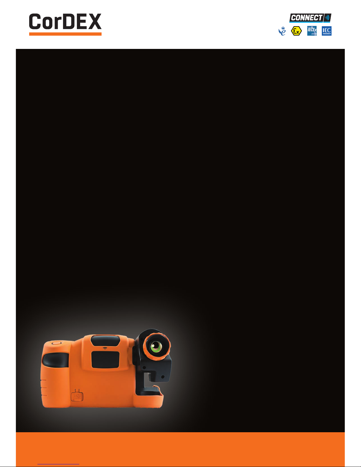
TC7000
INTRINSICALLY
SAFE THERMAL
IMAGING CAMERA
RUGGED AUTHORITY www.cord-ex.com
Page 2

TC7000 is certified ATEX/IECEx as follows:
• Ex ib IIC T4 Tamb -10ºC to +40ºC (Vapour)
• Ex ib IIIC T200ºC Db Tamb -10ºC to +40ºC (Dust)
• Ex ib I Mb (Mining)
Congratulations – You are
the owner of the first fully
radiometric thermal imaging
camera designed and certified
specifically for use in hazardous
(explosive) atmospheres.
CONTENTS
Getting To Know Your TC7000 4
Getting Started 6
A Guide To Charging Your TC7000 7
A Guide To Your Home Screen 8
Focus 9
Creating A Thermal Image 9
Menu Selection 11
RFID 12
Analysis 13
Settings 14
Parameters 15
Level/Span 16
Storing And Analysing Images 17
Technical Information 18
Certification 19
Ten Suggestions For Thermography Best Practice 22
Please ensure that the
certification matches or
exceeds the hazardous area
characteristics that will be
clearly displayed on site.
Whilst in a hazardous area, do
not attempt to change batteries
or download images, these
tasks should only be undertaken
after returning to a safe area.
! !
Page 3
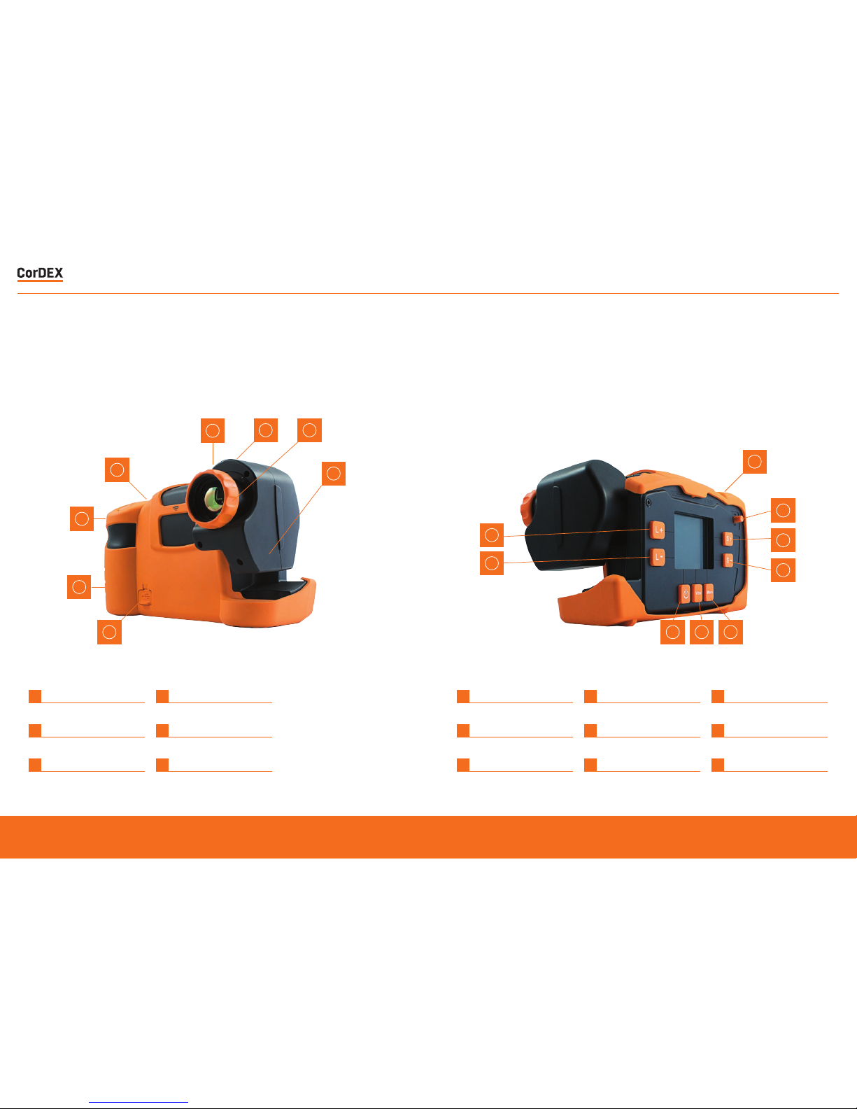
GETTING TO KNOW
YOUR TC7000
1
1
1
9
5
6
7
8
4
4
4
5
2
233
6
Focus Ring 135˚ Swivel Lens
1 4
Neck Strap Points Wrist Strap Points
2 5
RFID Scanner USB Connection Point
3 6
Focus Ring 135˚ Swivel Lens
1 4 7
Image Save Menu Key Level +
2 5 8
Power Switch Span + Level -
3 6 9
View Key Span - Joystick
RUGGED AUTHORITY
T7000 – Intrinsically Safe Thermal Imaging Camera
5
Page 4
Please Note: It is recommended
that users attend formal
thermography training to
understand the implication of
these parameters.
!
1
Remov e the bat tery from the bat tery
compar tment o f the camer a.
2
Plug the mains charging unit to a mains circuit
and plug t he jack fro m the chargi ng unit into
the battery station.
3
Inser t the bat tery into the bat tery charging
compar tment o n the bat tery charging sta tion.
A green light will sho w that the unit has
power. The charging light on the charging unit
will flash amber whil st the char ger assesses
the char ge held on the batter y. Follow ing this
a solid amber light will be display ed showing
that t he unit is charging.
4
When th e amber light i s no longer displayed,
the battery is fully charged.
5
Remov e the bat tery from the char ging
compartment.
6
Inser t the bat tery pack into the camera pay ing
caref ul att ention to t he orientation of the pack.
1
Check the content s of your TC 7000.
The shipping case should include the
following items:
• TC7000 Thermal Imaging Camera
• USB Communication Wand
• USD Documentation Key
• Certificate of Conformity
• Neck Strap
• Rechargeable Battery Pack
• Lens Cleaner
• Wrist Strap
• Access key
• Battery Charging Station and Mains
Charging unit
2
Please ensure that you fully charge the
battery pr ior to use. T he battery is char ged
using the docking station supplied.
(See page 7.)
3
Before using TC7000 consider the objects
that you are going to image. Will y ou use
comparative thermography (simply looking
for temperatur e diff erence) or ar e you going
to at tempt to make an accurate tempera ture
measurement?
4
For comparativ e thermography, do not
amend th e emissiv ity se tting and leave this
const ant ever y time you c arry ou t imaging.
Temperature differences over time will then
be valid although t he ambient temperature
may hav e changed as w ell as the electrical
or mechanical load of t he object .
5
For accurate ther mal measur ement the
emissi vity of the objec t will need t o be
considered and the c amera emissivit y
setting corrected.
In addition background and reflected ambient
will need to be consid ered as well as thermal
and solar reflect ion and rela tive humidity.
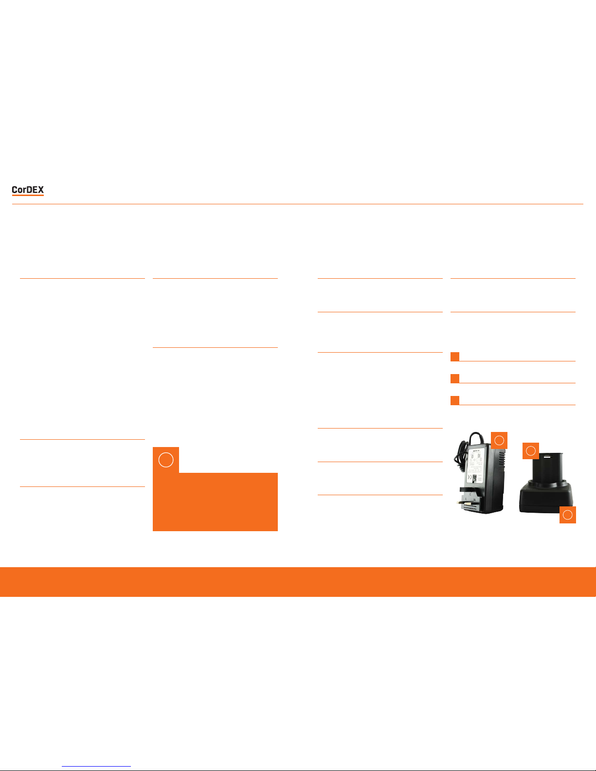
GETTING STARTED A GUIDE TO CHARGING
YOUR TC7000
1
Rechargeable/Removable Battery
2
Mains Charging Unit
3
Battery Charging Station
3
1
2
7
Inser t the bat tery pack into the camera pay ing
caref ul att ention to t he orientation of the pack.
8
Remov e battery when t he camera is no longer
in use. DO NOT REMOVE B ATTERY W HILST IN
HAZARDOUS AREA.
RUGGED AUTHORITY
T7000 – Intrinsically Safe Thermal Imaging Camera
7
Page 5

A GUIDE TO YOUR
HOME SCREEN
1
RFID Tag Status Bar
2
Temperature Reading Spot #1
3
Temperature Spot #1
4
Maximum Image Temerature
5
Temperature Scale
6
Minimum Image Temperature
7
Battery Charge Indicator
8
Ambient Temperature Selected
9
Reference Temperature Selected
10
Relative Humidity Selected
11
Emissivity Selected
12
IW Transmission Correction Icon
1
2
12 11 10 9 8 7
6
5
3
4
FOCUS
CRE AT I NG A
THERMAL IMAGE
• Correct f ocus is cri tical in pr oducing an
effective thermal image. Slowly rot ate the
knur led orange Focus Ring on the front of
the lens u ntil the ob ject is clearly in vie w.
You may find t hat the bes t focus is easier
to achie ve using a grey scale pale tte. Make
sure th at you focus on the objec t to be
measured rather than the background.
• S witch on the TC70 00 by press ing and
holding t he power s witch for at least 3
seconds.
• Ensure auto Level/Span is enable d.
(See S ettings section on P.13)
• Ensure that camera is correctly focused.
• You should now see a h igh qualit y thermal
image and b e able to discern small spa tial
and temperature dif ferences.
• Spots (crosshairs) can be moved by using
the joy stick. The temper ature at that point
is displa yed on the top left of the display.
When th e crosshair is highlighted, pressing
and holdi ng the joys tick will a llow the
emissi vity of that spo t only to be changed.
RUGGED AUTHORITY
T7000 – Intrinsically Safe Thermal Imaging Camera
9
Page 6

• Pressing the joystick again will highlight
each spo t in turn. T his is follo wed by the
optio n for the TC 7000 to scan for an RFID
tag. Place the top f ront of the camera within
5 cm of an RFID tag and press/hold the
joystick again. T he RFID tag informa tion
will be displayed and can be edited. (See
detailed RFID Sec tion on P.11)
MENU SELECTION
• All other camera settings and features are
selected through the menu button. Press this
once to display 6 icons.
• When the NUC icon is highlighted one press
of the joystick will perform a manual Non
Uniformity Correction (NUC). This should
not be required in normal use as the NUC
is carried out automatically when required.
A distinct click will be heard when the
NUC is performed and the thermal image
will be refreshed. A manual NUC may be
required when moving to different ambient
temperatures but very frequent NUC
operation will seriously impact battery life.
• When the analysis icon is highlighted
moving the joystick down will cycle through
crosshair (spot) selection (0,1,2 or 3),
maximum temperature display (within entire
image), minimum temperature display (within
entire image). (See detailed analysis section
on P.12)
• The settings icon enables the user to select
or deselect all of the display settings. (See
detailed Settings section on P.13)
• The parameters icon allows all the
measurement parameters of the
thermal image to be altered to increase
temperature measurement accuracy. These
include emissivity, ambient temperature,
atmospheric temperature, relative
humidity and target distance. (See detailed
parameters section on P.14)
• The clock icon enables setting of all time
and date information.
• The info icon displays camera serial number,
internal memory used, remaining internal
memory and battery capacity.
RUGGED AUTHORITY
T7000 – Intrinsically Safe Thermal Imaging Camera
11
Page 7

RFID ANALYSIS
• When an RFID tag is located an RFID details
menu will be displayed which shows the
hexadecimal identification of the RFID tag.
• It is recommended that an alias is then
added for future identification the tag
location . Use the joystick to highlight the
alias section (complete with selecting OK)
and then input a simple description through
the qwerty options (complete with selecting
OK - this can be edited later in CorDEX
CONNECT)
• Select whether the RFID Tag is built into
a CorDEX IR window (IW2000, IW3000,
IW4000) or if it is a stand alone tag (NON
CDX).
• With the RFID tag editing complete select
SAVE to store this information for future use.
There ar e three set tings in the analysis menu:
1
The No. spots icon allows choice of 0, 1, 2 or
3 temperature spots (crosshairs) within the
display that will update in real time
2
The Hi icon enables and disables dis play of
maximum tempera ture wi thin the ima ge as a
red spo t (crosshair). This temperatur e will be
the same as the top of t he tempera ture range
in auto span/level.
3
The Lo i con enables and disables display of
minimum t emperat ure within the image a s a
blue spo t (crosshair) This tempe rature w ill be
the same as the bot tom of the t emperat ure
range in auto span/ level.
RUGGED AUTHORITY
T7000 – Intrinsically Safe Thermal Imaging Camera
13
Page 8

SETTINGS PARAMETERS
There ar e 10 icons in the Settings Menu
1
The Scale Icon toggles the display of the
temperature colour scale.
2
The Info Fields Icon allows dis play of relative
humidi ty only, reference and ambient
temper atures only, emissivity only or all.
3
To Save batter y life the A uto Of f Icon allows
a choice o f 2, 5 or 10 minu tes of no activit y
before auto of f. The of f set ting disables this
feature.
4
The Au to S/L Icon t oggles bet ween ena bling
the auto span and level setting where highest
and low est temper atures s een within the
image are always displayed and manual
level and span where the user can manually
select span and level to adjust displayed
temperature range.
5
The Voic e Tag Icon enables a nd disables v oice
annotation when saving files.
6
The Text Tag Icon enables an d disables text
annotation when saving files.
There ar e 5 icons in the parameters menu
all allowing the user to input tempera ture
measurement parameters to increase
measurement accuracy.
1
The Emissivity Icon accepts input of object
emissivity.
2
The Amb Temp Icon accepts input of o bject
ambient temperature.
3
The Atmos Temp Icon accepts input of
atmospheric temperature.
4
The Rel Humidit y Icon accepts input of r elative
humidity.
5
The Targe t Dist Icon accepts input of camer a
distance from target obje ct.
7
The Palette Icon allows the user to choose
bet ween grey scale (bl ack hot), greyscale
(white hot), ironbow, hotmetal, rainbow, amber
and sepia colour palettes.
8
The Temper ature Units Icon all ows the user
to choos e either Celsius, Fahrenheit or Kelvin
temperature display
9
The Temper ature Units Icon all ows the user
to choos e either Celsius, Fahrenheit or Kelvin
temperature display
10
The Periodic Save Icon allows the user to set
the camera to automaticall y save an image
ever y 10 secon ds, 30 seconds or one minute.
(T his is the same as pressing the image save
but ton on the camera)
RUGGED AUTHORITY
T7000 – Intrinsically Safe Thermal Imaging Camera
15
Page 9

LEVEL/SPAN STORING AND
ANALYSING IMAGES
• Two settings are fundamental to obtaining
an effective thermal image, the first is clear
focus and the second is the correct thermal
range which is adjusted by Level and Span
Settings.
• With Auto Level and Span enabled in the
Settings Menu the range is automatically
adjusted to display both the hottest and
coldest temperature within the field of view.
• When more sensitivity is required level and
span must be set manually by disabling
auto level/span in the Settings Menu and
using the L+/Land S+/S- buttons on the
rear of the camera. Start by increasing the
span (sensitivity) to the required setting and
then increase or decrease the level (range)
so that the object is visible at the required
sensitivity.
• The Image Save Button on top of the
handgrip is used to store images (except
when periodic save is enabled).
• When you want to save an image, press the
Image Save Button and a Save Image menu
will appear. Use the joystick to select yes
and press joystick to save.
• If RFID scan is enabled in the Settings Menu
you will be asked to scan an RFID tag to link
the saved image to a location.
• If text annotation is enabled in the Settings
Menu you will be asked to select one of 4
pre-programmed text comments. After this
the image is stored in the camera memory.
• If voice annotation is enabled in the Settings
Menu you will be asked to record your
message. Press the joystick on the Record
Button, speak (maximum ten seconds) and
then press the joystick on the Stop Button
to finish.
• To review saved images within the camera
press VIEW on the rear of the camera and
use the joystick to select the image required.
Pressing the joystick will display the stored
image full size on the camera display
showing all of the parameters displayed
when the image was saved. Moving the
joystick up and down will change the display
colour palette.
RUGGED AUTHORITY
T7000 – Intrinsically Safe Thermal Imaging Camera
17
Page 10

Certificate Information
ATEX / IECEx Certificate No TRAC12ATEX0037X / IECEx TRC 12.0019X
ATEX / IECEx Certificate Types • Ex ib IIC T4 Gb Tamb -10°C to +40°C (Vapor)
• Ex ib IIIC T200°C Db Tamb -10°C to +40°C (Dust)
• Ex ib I Mb (Mining)
Temperature Information
Measurement Range -4°F to 1112°F (-20°C to +600°C )
Accuracy ± 2°C or 2% of reading
Imaging
Image Frequency 9Hz
Detector 320 x 240 uncooled microbolometer
Thermal Sensitivity/NETD 50mK
Spectral Range 8μm to 14μm
Field of View (FOV) 25° x 20.5°
Spatial resolution (IFOV) 1.38 mrad
Minimum focus distance ≈ 4” (10cm)
Lens F 1.2
Image Capture
File Storage 8GB
File Formats CDX (Radiometric) JPEG (Non-radiometric)
Voice Annotation YES
RFID Tag Reader • Operates with 13.54MHz passive tags
• Detection range up to 5cm (1.9in)
• SupportsISO/IEC15693-2,ISO/IEC18000-3 tag formats
General
Operating Temperature -4°F to 104°F (-20°C to +40°C)
Storage Temperature -40°F to +158°F (-40°C to +70°C)
Display 3.2” Backlit LCD
Software CorDEX CONNECT (Included)
Batteries Removable and Rechargeable
Battery Life Upto 8 hours
RUGGED AUTHORITY
T7000 – Intrinsically Safe Thermal Imaging Camera
19
Page 11

RUGGED AUTHORITY
T7000 – Intrinsically Safe Thermal Imaging Camera
21
Page 12

TEN SUGGESTIONS FOR
THERMOGRAPHY BEST PRACTICE
1
Ensure that the electrical or mechanical
system you are imaging is running fully loaded
to highlight thermal anomalies. A fully loaded
system will generate higher temperature
differential making it simpler to identify
problems.
2
Ensure y our image is in f ocus – this is
impor tant not only for ima ge clarit y but also
accurate temperatur e discrimination and
measur ement. Fo cus should al ways be se t to
the obje ct being mea sured eve n if this means
that a surrounding area may be out of focus.
3
If wor king in a Zon e 1 Hazardous area, ensu re
that your thermal imaging camera is marked
with the appropriate cer tification to avoid
risk of explosion. Employers are required
to identify hazardous areas clear ly for both
employees and contractors.
4
If you ar e looking f or temperatures ab ove
or below a temperat ure threshold, use an
isotherm or max imum temper ature within an
area feature to clearly highlight any excess.
These features save tim e and increase
awareness as sur veys can take several
hours w here fat igue could cause an impor tant
anomaly to be overlooked.
5
Obser ve a scene f rom dif feren t angles to
minimise thermal reflection as an unusual
warm ar ea could jus t be your own thermal
reflection. Minimise solar r eflecti on on display
screens outdoors by changing your stance or
swivelling the lens to eliminate reflection.
6
Alwa ys conside r the object emissivity firs t
if you want to come close to an accur ate
temperature measurement, but remember
that r egular comparativ e thermography will
also sho w temperature changes leading to
potential failure.
7
For comparative thermography, ensure that
thermal camera sett ings and especially
emissivit y remain consistent. Ideally system
load should also be similar althou gh this is
often impractical.
8
Use inf rared windows to image electrical
switchgear under full load in safet y. Never
open cabinet doors or override protection
devices, this will put you at serious r isk of
injur y from arc flash. Even a change of air flow
or dust and debris being dislodged can trigger
an arc flash incident .
9
Alwa ys store images and relate them w here
possible to visible images whe n building a
Repor t. This makes it easier to pinpoin t the
fault f or schedul ed maintenance. Choos e a
repor ting software packag e that makes this
process simple and consider installing RFID
tags to link measurements fr om diff erent
technologies to one specific location.
10
Repor t critical items s eparately in the Report
and draw attention to them clearly – t he
whole idea of ther mography for preventive
maintenance is to find faults and fix them
before they cause a breakdo wn and loss
of production or uptime. Cho ose a repor t
sof tware p ackage that create s a scheduled
job shee t to pass straight to the maintenance
engineer.
RUGGED AUTHORITY
T7000 – Intrinsically Safe Thermal Imaging Camera
23
Page 13

Copyright © 2014, CorDEX Instruments Limited.
All other brand and product names are
trademarks of CorDEX Instruments Limited.
Ref.ID 7000-MAN, Rev.A
 Loading...