

Page 1
USER
MANUAL
MN4000 & MN4100
SERIES THERMAL
IMAGING CAMERAS
RUGGED AUTHORITY www.cord-ex.com
Page 2

Congratulations – You are the
owner of a MONITIR Series
Thermal Imager.
CONTENTS
Introduction 8
Quick Start Guide 10
Mechanical Installation 12
Important Network Information & Parameters 13
Camera web server 14
CorDEX MONITIR software 15
MODBUS & HTML 15
IP Addressing 17
Factory Reset 17
CE Declaration of Conformity 17
Page 3

REGISTER
YOUR
PRODUCT.
www.cord-ex.comRUGGED AUTHORITY
Register your product now
at http://www.cord-ex.com/
register-your-product/ and
receive a 12 month extended
warranty.
Terms & Conditions apply.
OVERVIEW
The CorDEX Instruments, MN4xx x series
of continuous monitoring cameras offer an
affordable and accurate means of continuously
monitoring temperature either as a standalone
unit, or a s part of a lar ger contro l system/
strategy.
The Cor DEX MN4xxx camera plat forms ar e
designed primarily with Industr y Control &
Monitoring in mind and as such, are provided
with the industr y standard communication
ability, MODBUS/TCP for communicating
with devices such as Programmable Logic
Controllers (PLCs).
The Cor DEX MN4xxx may b e installe d in a
stand alone or multi camera mo de, with each
camera i ncorpor ating a buil t in web ser ver for
basic se tup purposes which i s accessibl e via
a stand ard web bro wser using Ethernet /IP,
additional CorDEX PC Setup Sof tware is also
available for download.
CorDEX MNxx x cameras are also supplied
with PLC Function Blocks for popular brands.
These prewritten code blocks ar e designed
to drama ticall y reduce the amount of time
requir ed to integrate and MN 4xxx in to a PLC
programme by enabling programmers to
simply select a block and drop th e code into
the PL C ladder logic. Functio n Blocks are
continuously added to the CorDEX MN4xx x
website and include; Communications, Analysis
and Alarming blocks.
RUGGED AUTHORITY
Page 4
1
Install the camera.
2
Download the CorDEX MONITIR PC Application from
www.cord-ex.com/products/monitir-software/
3
Connect power via the standard screwed terminal
block provided (11-20VDC).
MN4000 MN4100
4
Connect the camera to your PC using a USB
cable.
Connect the camera to your PLC using an Ethernet
cable.
5
Start the CorDEX MONITIR PC App.
6
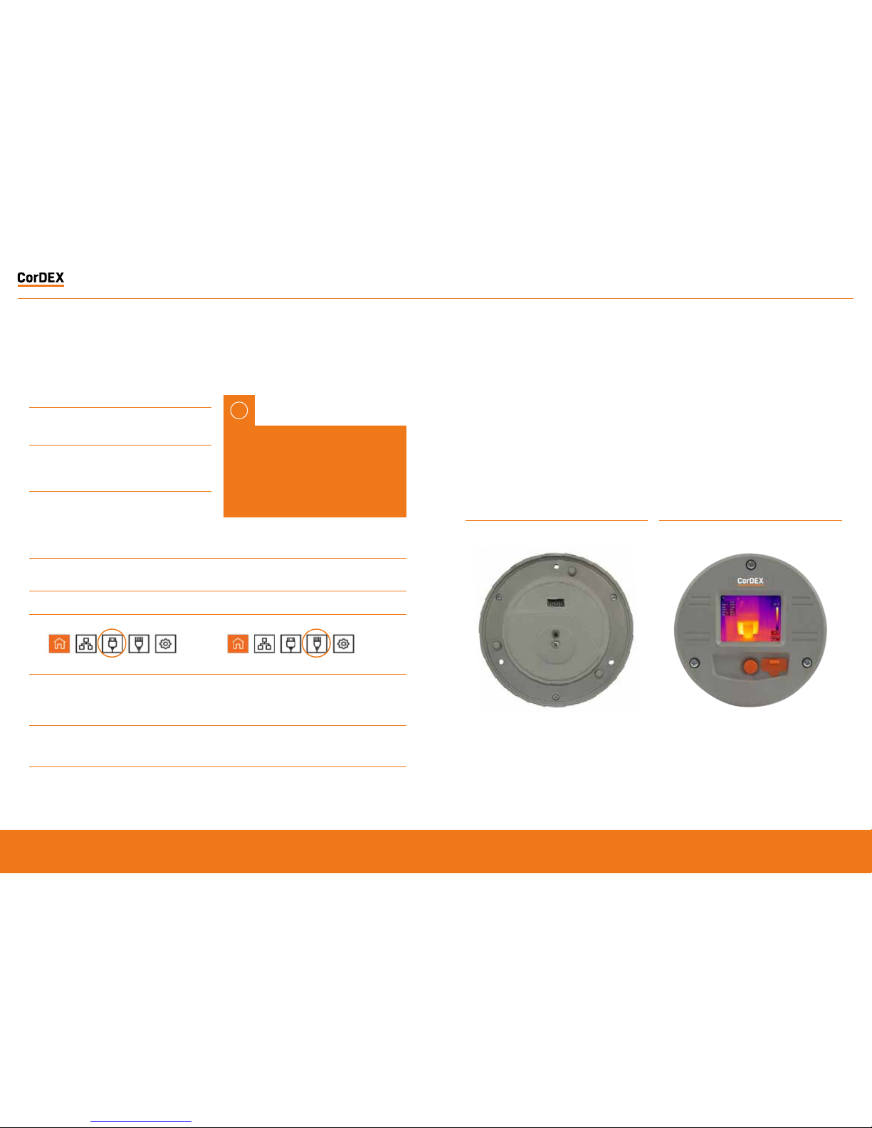
Select Direct Connect USB icon. Select Direct Connect Ethernet icon.
7
You have now accessed the CorDEX MN4000
series camera. From this screen you can setup
and provide basic control commands to the
camera.
Input the camera fixed static IP address
192.168.1.100 into the box and click Connect.
8
Click Submit. The camera will now restart with
desired settings.
You have now accessed the CorDEX MN4100 series
camera. From this screen you can setup and provide
basic control commands to the camera.
9
- Click Submit. The camera will now restart with
desired settings.
QUICK START GUIDE MECHANICAL INSTALLATION
MN4000
The Cor DEX MN4 000 panel mo unted the rmal
imager is intended for permanent installation
into electrical panels. Installation is achieved
in tw o stages.
Once th e chassis has b een installed, the
camera p ackage can b e removed a nd
replaced without shut ting down or interrupting
the panel.
IMPORTANT NOTICE, MN4100
CAMERAS ARE SHIPPED WITH A
PREFIXED STATIC IP ADDRESS OF
192.168.1.100. This can be altered
using the CorDEX MONITIR PC App
(recommended).
1
Install the Chassis into the panel.
2
Attach the Camera Package to the chassis.
!
RUGGED AUTHORITY
MONITIR Series Thermal Imaging Cameras – User Manual
7
Document Reference MONITIRSERIESUM Rev. A
Page 5
Installation of MN4000 Chassis
WARNING: Working on electrical equipment
prese nts signi ficant r isk and shoul d only be
undertaken by suitably qualified per sonnel
in accordance with local applicable codes,
standards and corresponding Personal
Prot ectiv e Equipmen t (PPE) . This inst allati on
proce dure assu mes a panel ha s been saf ely
remo ved and tra nsport ed to a suit able loca tion.
!
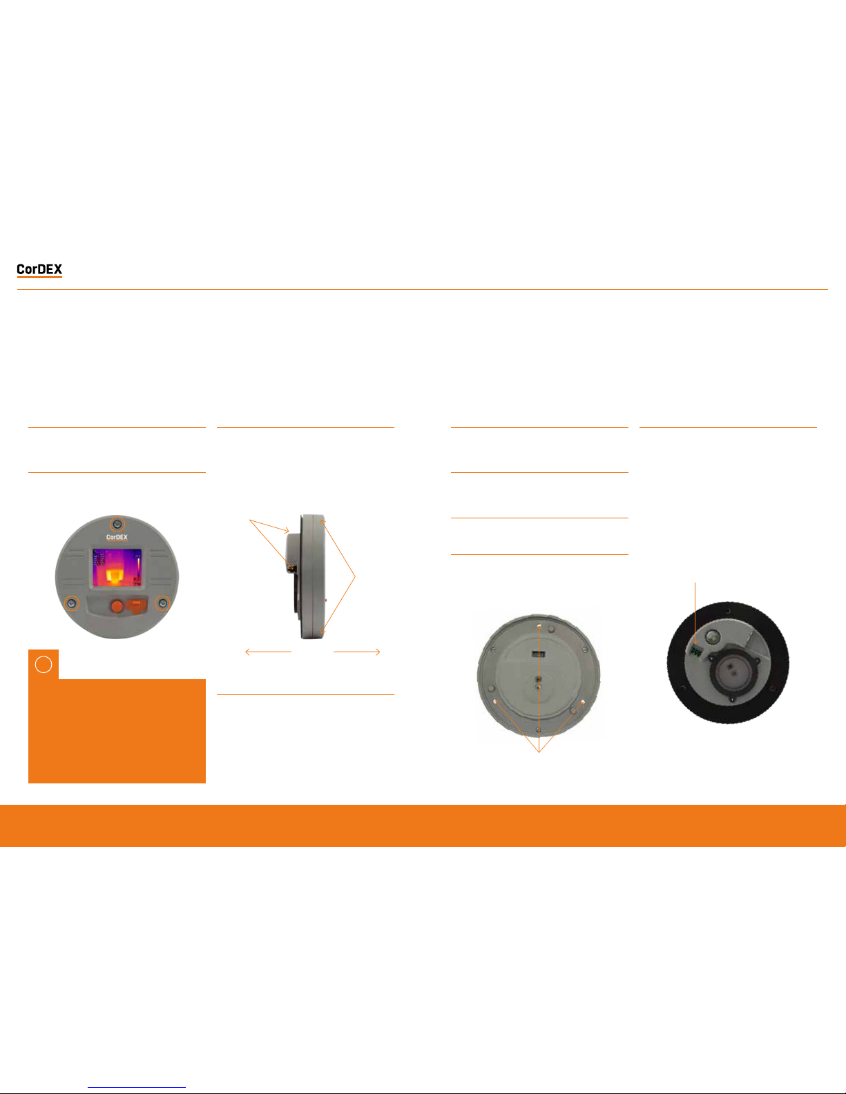
1
Remove the MN4000 from its packaging and place on
a flat surface, taking care not to scratch the lens.
2
Remove the three screws securing the Camera
Package to the Chassis.
3
Separate the Camera Package from the Chassis by
holding the Chassis communication bulge in one hand
and the Camera Package edge in the other hand then
gently but firmly pull apart.
4
Place the self-adhesive drilling template provided
into the desired location. Care should be taken to
ensure the rear of the panel is clear of ribs or other
obstructions prior to drilling.
5
Using the drill bit specified on the template (xxx), drill
the three fixing holes located around the perimeter.
6
Using an appropriate holes saw or punch, drill the
large (95mm/3¾”) centre hole.
7
Debur all rough edges and treat with rust inhibitor.
8
Align Chassis with mounting holes and attach using
three self-tapping screws provided, making sure to
advance the screws evenly.
9
Connect 11-30VDC to the green power connector
(provided) and attached to Chassis. There are three
connections.
Top: 0V
Centre: Supplemental GND*
Bottom: +ve
*GND is a supplemental Ground connection. MN4000 Primary
Ground is via the RJ45 socket and communications line. If no
communications are installed, the Supplemental GND may
be connected in accordance with local Electrical Codes /
Regulatory Requirements.
Separate
Grip here
Grip here
Chassis mounting holes
Power connections here
RUGGED AUTHORITY
MONITIR Series Thermal Imaging Cameras – User Manual
9
Document Reference MONITIRSERIESUM Rev. A
Page 6
11
Replace the panel and secure before aligning the
Camera Package with the Chassis and fasten into
place with three fixing screws provided.
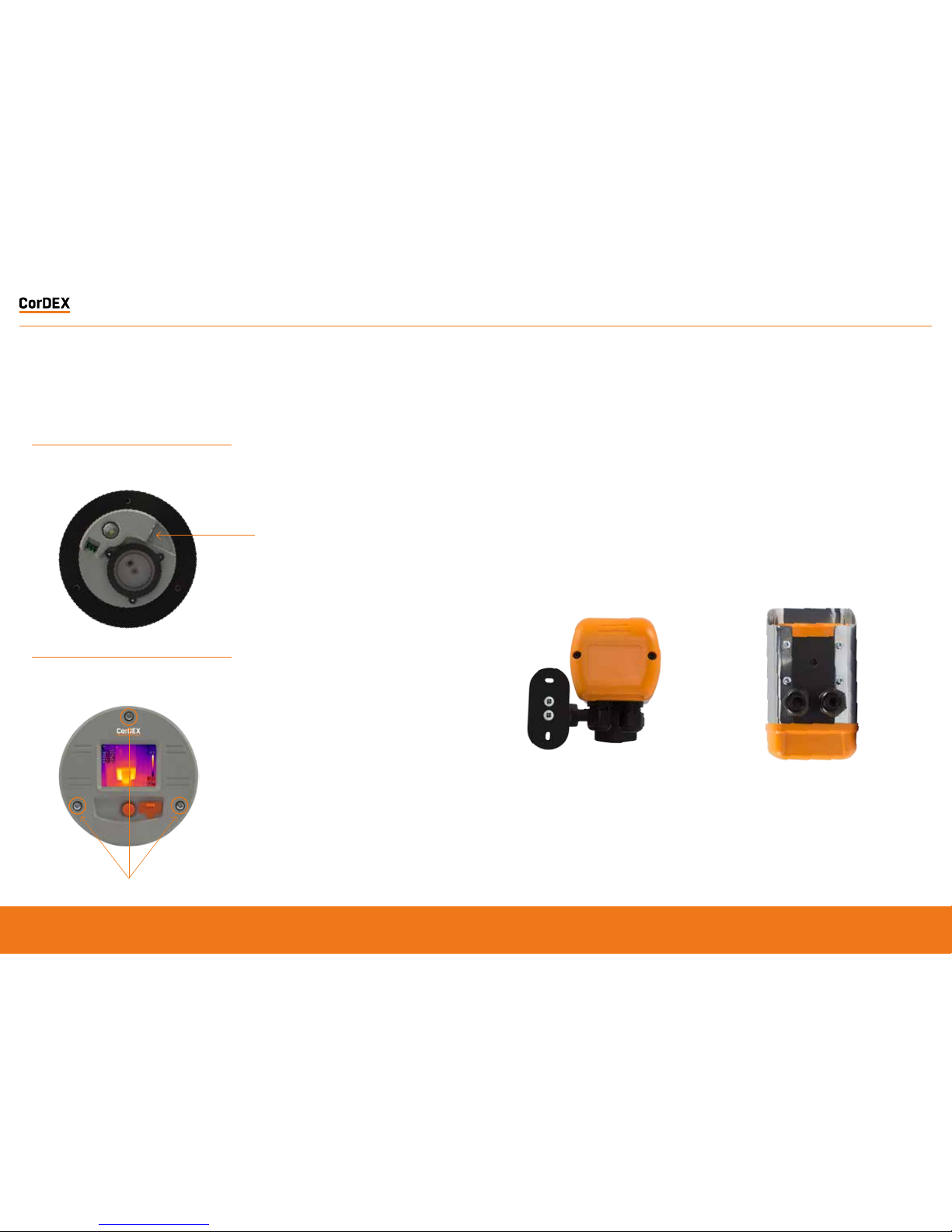
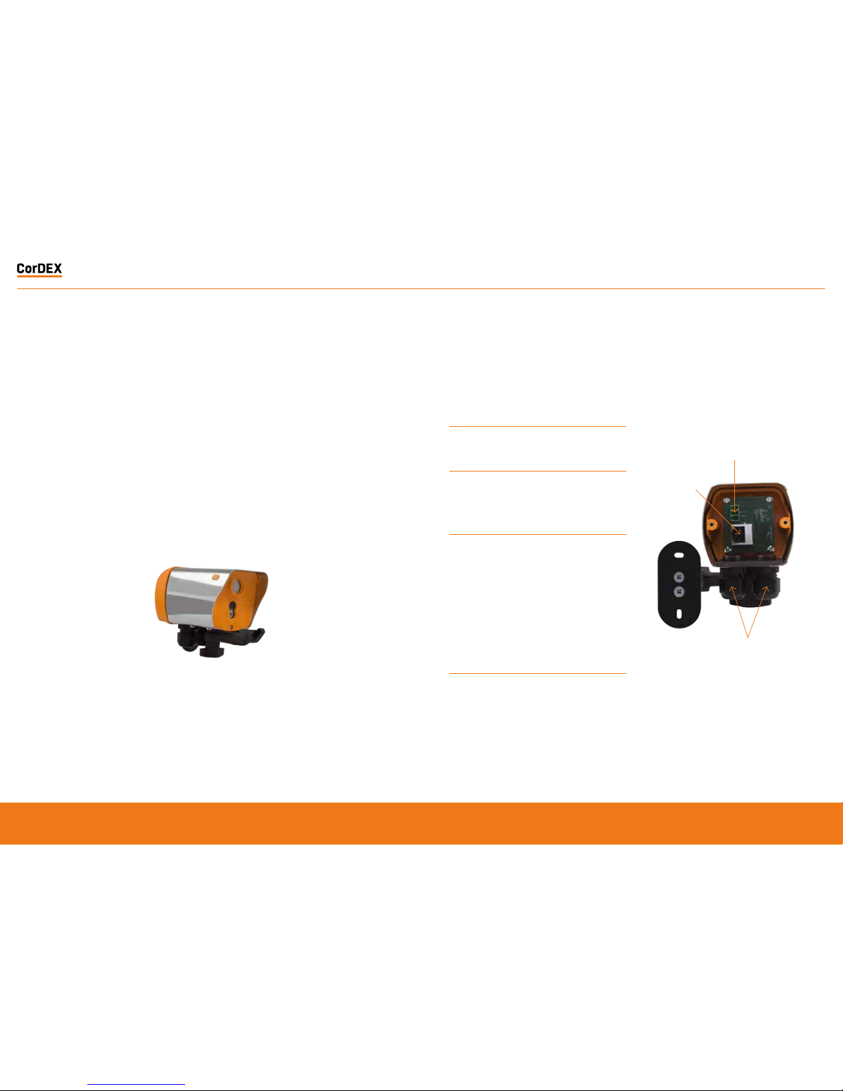
MN4100 attached to CDX8900-470
mounting arm.
MN4100 Base showing M6x4 mounting
boss and two compression glands.
Ethernet connection here
MN4100
The CorDEX MN4100 industrial automation
thermal imager is intended for permanent
installation into fixed locations for industrial
automation, control and safet y monitoring
purpo ses. Inst allation is via an M6x4 threaded
boss loc ated on the base of the camera
and optional mounting arm, part number
CDX8900-470 is also available.
10
If communications are to be used, connect an
Ethernet cable with RJ45 plug to Chassis.
Chassis mounting screws
RUGGED AUTHORITY
MONITIR Series Thermal Imaging Cameras – User Manual
11
Document Reference MONITIRSERIESUM Rev. A
Page 7
Installation of MN41 00
This installation procedure assumes that
mechanical mounting and positioning has
already occurred, for specific mounting
instructions relating to CDX8900- 470, please
view t he MN410 0 Mounting A rm Insta llation
Manual.
A typical industrial installation will comprise
of arm oured cable f or both po wer and
communications, terminating in a junction box
adjacent to the camera. Unarm oured pow er
and communicatio ns cables are run from t he
junct ion box to the c amera via t he two M 16
compression gland e ntries l ocated in t he
camera base.
Typical camera installation diagram
1
Remove rear weather cap from camera to expose
Ethernet socket and power terminals.
2
Insert power and communications cables into camera
via 2xM16 compression glands provided. NOTE, these
glands will accept cables with outside diameters from
3mm – 7mm.
3
Connect 11-30VDC to the green power connector
(provided) and attached to Chassis. There are three
connections
Top: 0V
Centre: Supplemental GND*
Bottom: +ve
*GND is a supplemental Ground connection. MN4000 Primary
Ground is via the RJ45 socket and communications line. If no
communications are installed, the Supplemental GND may
be connected in accordance with local Electrical Codes /
Regulatory Requirements.
4
Attached an RJ45 plug to the communications cable.
DO NOT PLUG INTO THE CAMERA AT THIS STAGE.
Power connector
RJ45 Socket
Compression glands
RUGGED AUTHORITY
MONITIR Series Thermal Imaging Cameras – User Manual
13
Document Reference MONITIRSERIESUM Rev. A
Page 8

5
Connect camera to a PC running CorDEX MONITIR
software, select Direct Connection, Ethernet and
use the default address 192.168.1.100. You can now
configure the camera for your network, for more
information on CorDEX MONITIR Application, please
refer to the specific software user manual.
6
Once the camera has been locally configured for your
network, attach the RJ45 connector and replace the
weather cover.
7
The camera is now ready for use.
NETWORK INFORMATION
AND PARAMETERS
IMPORTANT NOTICE
CorDEX MN4000 cameras are shipped as DHCP enabled as setup configuration is via the
USB port located on the front of the camera.
CorDEX MN4100 cameras are shipped with a STATIC IP ADDRESS of 192.168.1. 100 This is
the default address the CorDEX MONITIR PC Application uses in Direct Ethernet Connect
mode when communicating with the camera during initial setup.
Please refer to your Network Administrator and obtain the correct parameters before
connecting MN4xxx cameras to your network.
RUGGED AUTHORITY
MONITIR Series Thermal Imaging Cameras – User Manual
15
Document Reference MONITIRSERIESUM Rev. A
Page 9

CAMERA WEB
SERVER INTERFACE
EACH C ORDEX MN 4XXX CAMERA I S SUPPL IED WIT H AN ONBOA RD WEB IN TERFACE .
Accessing the web interface
To access the web inter face, o pen your
inter net brow ser and in the a ddress bar t ype
the IP Address of th e camera you w ish to
communicate with.
The spe ed of the ne twork c onnecti on will
deter mine the ra te at whic h the camera
responds.
The ima ge shown is a snapshot and n ot a live
feed, t o reload an im age, click Re fresh Image.
Ther mal data is captured and made avail able
for machine vision /automat ion at a fre quency
of 9Hz .
Home tab
The Hom e tab is the de fault tab a fter lo gging
into the camera. Un der the Home t ab, it is
possible to change the image type, image
colourisation, set rising and falling isotherms
and to toggle the onbo ard LED.
IP Addr ess
Image type Example image
Highlight
Combi nes visua l and therm al images in to one wi th the
hottest areas bleeding through the visual.
Visible only
The vi sible imag e captur ed by the 64 0x480 onbo ard
digital camera.
Select ing the corr ect Image Type
The cam era captu res both v isual and th ermal
images simultaneously, your choice of Image
Type determines w hich of four options a re
displayed on the screen.
RUGGED AUTHORITY
MONITIR Series Thermal Imaging Cameras – User Manual
17
Document Reference MONITIRSERIESUM Rev. A
Page 10

Thermal only
The th ermal ima ge captur ed by the 8 0x60 inf rared
camer a. Due to the r esolut ion of the i nfrar ed camera
alone , this mode is n ot recom mended fo r scenes wi th a
low dynamic temperature range.
Isotherm overlay
When a r ising and /or falling is otherm i s configur ed and
Isot herm ove rlay sele cted, th e areas wh ich fall in to
the Isotherm alarm condition are coloured and shown
on the image. This example has both rising and falling
isot herms con figured . The risin g isothe rm is show n in
red/or ange, th e falling is otherm i s show in pur ple.
To select an Image Type, cli ck the drop down
box and select the desired option, then cli ck
the Sen d to Camera bu tton. T he command w ill
be tran smitt ed to the came ra and the ima ge
ref reshed af ter a few moments w ith your n ew
settings applied.
Setting Rising/Falling Iso therms
An Isotherm is an al arm condi tion wher e a
temper ature le vel which i s above (ris ing) or
below ( falling ) the Isoth erm setp oint cause s
the imag e in that set location t o be highligh ted
on the v isual image b y means of a colour.
To Set a Risin g Isother m, click the O FF/ON
toggle s witch to the ON posi tion (gr een) and
inser t the alar m value in the b ox adjacent t o
the button.
Click “S end to Camera”.
Any tem peratur e in the cameras Field of V iew
(FOV ) above t his temper ature wi ll be coloured.
To Set a Fallin g Isother m, click the O FF/ON
toggle s witch to the ON posi tion (gr een) and
inser t the alar m value in the b ox adjacent t o
the button.
Click “S end to Camera”.
Any tem peratur e in the cameras Field of V iew
(FOV ) below t his tempera ture will be coloure d.
It is pos sible to set b oth Rising and
Falling Is otherm s on the same ca mera
simultaneously.
Toggling the onboard LED illuminator
The cam era is equipp ed with an o nboard LED
illuminator for extremely low light situa tions.
To toggle th e LED illumin ator, click the LED
OFF/ON but ton and then click the S end to
Camera button.
Spot temperatures
The cam era has thr ee spot temp eratur e
points; Hot, Cold and Dynamic.
The Ho t temperat ure ident ifier puts a red
cross o n the hot test par t of the image.
The Col d temperature identifier pu ts a blue
cross o n the coldes t part of t he image.
The Dynamic tempera ture measurement
shows t he temper ature of t he cursor in t he
Spot Temperature box.
MODBUS Registers & Coordinates
When Co nfiguring P rogramm able Logic
Controllers (PLCs) to perform actions based
upon MN4 xxx measuremen ts, it is nec essary
to be able t o define either the MOD BUS
Register of a par ticular point in the image
and/or its x,y coordinates.
To do this, ho ver the mou se over the p oint
on the ima ge you are in terested in and the
MODBU S Reg will be sh own in the Modbus
Reg field , in brackets, the x,y coordinate s for
the sam e MODBUS Reg ister are sh own.
RUGGED AUTHORITY
MONITIR Series Thermal Imaging Cameras – User Manual
19
Document Reference MONITIRSERIESUM Rev. A
Page 11

Alarm Tab
The Al arm tab opens the grid al arm page of
the MN4xxx webserver. Each MN4xxx camera
can acco mmodate a 5x 5 grid squar e with a
config urable ris ing alarm in each square.
When a gr id squares m aximum temperature
exceeds its alarm t hreshol d the alarm bell
noti fication on the home page activates and
a speci fic regist er in the MODB US table is
toggled.
Sett ing a grid alar m
To set a grid a larm, click the grid square of
inter est and the a larm set up box will app ear.
Selec t ON from th e Alarm OFF/ON t oggle and
enter t he Rising Iso therm ala rm value. T hen
click Upd ate, foll owed by Submit.
The gr id square alarm is now ac tive and c an
be moni tored usin g a PLC to check for the
MODBU S Register b it associa ted wit h that
speci fic grid. For more info rmation, see page
26, MODB US & HTML .
Settings
The Se ttings tab allows u sers to con figure
the cam era Locat ion Name, t he units of
measurement and network setup information.
The Lo cation Na me is a unique ide ntifier input
by the in staller w hich pinpoin ts the camera
locat ion, once se t, this should not be cha nged
unless t he camera du ty is altered.
The uni t of measur e can be selec ted from
three potential options; Celcius, Fahrenheit
and Kel vin.
DHCP Server enable, Ip Address, Subnet Mask
and Gat eway can all b e manually c onfigured in
the Se ttings t ab.
Once com plete, cli ck Apply and the set tings
will be t ransmit ted to th e camera.
CorDEX MONITIR Software
The Cor DEX MN4xxx ser ies camera s are
intended for inst allatio ns of all sizes; from a
single ca mera, to hun dreds. For l arge scale
installations, determining one camera from
another on a network becomes problematic
To overcome this CorDEX have developed
CorDEX MONITIR PC Application.
MONITIR is an expandable application, initially
used to setup one or mo re cameras a s part
of the in stallat ion process. Once ins tallation
is complete, MONI TIR can the n be used
to access ever y camera on th e netwo rk
rem otel y.
To downlo ad the CorD EX MONIT IR Sof tware ,
please v isit ww w.cord-ex.com/products/
monitir-soft ware/
RUGGED AUTHORITY
MONITIR Series Thermal Imaging Cameras – User Manual
21
Document Reference MONITIRSERIESUM Rev. A
Page 12

Homepage
The CorDEX MONITIR PC Application is
intended for set up purpos es both of a
standalone camera and also to aid PLC
Integration.
The Ap plicatio n is broken do wn into t wo
main met hods of com municati on; Netw ork
Discovery and D irect Connect.
Network
Discovery
Settings
Direct Connect
(USB)
Direct Connect
(Ethernet)
Network Discover y
Net work Disc over is int ended to iden tif y
all Cor DEX MN4x xx camer as located on a
net work. T his is achie ved by broadcastin g a
message across th e network, to w hich each
camera responds providing;
1. Instr ument Type – T his refer s to camera
type (Factor y set)
2. Loca tion – This is a d escript ion,
uploaded to the came ra during in itial
installation/setup, that provides a
means of identif ying w here the ca mera
is located in a par ticular fa cility. ( User
configurable)
3. Ip Addre ss – The IP Addr ess of the
camera (User configurable)
4. Mac Addr ess – The Mac A ddress of t he
camera ( Factor y set)
5. Serial Number – The Ser ial Number of
the cam era (Fact ory set )
To deploy Ne twor k Discover y from t he
homepage, ensure the PC running MONITIR
is conne cted to the s ame net work as the
MN4x xx camer as and click th e Netwo rk
Discovery ico n, the Net work Discover y page
will appear and the us er prompt ed to begin
the Discovery process.
Once com plete, th e window w ill be popula ted
wit h all the cameras which ha ve respon ded to
the Network Discov ery broadcast message.
Double clicking on a pa rticular camera w ill
open the corresp onding set up page, thi s is the
same pag e as Direct C onnect Eth ernet.
RUGGED AUTHORITY
MONITIR Series Thermal Imaging Cameras – User Manual
23
Document Reference MONITIRSERIESUM Rev. A
Page 13

Direct Connect (USB)
MN40 00 Cameras c an be configu red via th e
chassis in Direct Co nnect Ethe rnet mode o r
when in stalled and in use, via Direct Conne ct
USB mod e, this is the r ecommend ed mode of
communication for initial setup.
To communic ate via Dir ect Conne ct USB, fir st
ensure t he MN4000 is power ed up and the
PC running MONITIR Application is connected
to the USB port lo cated on th e front o f the
camera.
Direct Connect (Ethernet )
Both M N4000 and MN4100 ha ve the capa bility
for a dir ect, PC to C amera Ethe rnet conn ection
using th e MONITIR P C Applica tion. Dir ect
Connec t (Ether net) is the r ecommend ed initial
setup mode for MN4 100 camer as as they ar e
shipped with a factory s et static IP address .
To communic ate wit h the camera, ensure
the PC r unning the M ONITIR A pplicati on is
connec ted to the camera wit h an Ethern et
cable, t hen click th e Direct Connect (Et hernet)
icon from the homepage.
Then click the Dire ct Connec t (USB) ico n
from t he home scr een and the Ap plication
will communicate d irectl y with t he camera,
displa ying ret urned dat a in the foll owing
format.
If this is a first time setup of an M N4000, t ype
192. 168.1 .100 in to the Ip address box and cl ick
Connec t. If this is not a first t ime setup , you
must t ype the Ip a ddress ass ociated w ith your
specific camera.
RUGGED AUTHORITY
MONITIR Series Thermal Imaging Cameras – User Manual
25
Document Reference MONITIRSERIESUM Rev. A
Page 14

MODBUS & HTML
The MN 4000 and MN 4100 hav e Modbus
TCP and H TML access for mage display and
analysis.
MODBUS/TCP
The Mod bus proto col used is Mod bus TCP/
IP also k nown as Mod bus TCP. htt p://www.
modbus.org/docs/Modbus_Messaging _
Implementation_ Guide_V1_0b.pdf
Following Modbus command function codes
are used:
• Function code 3: Read Multiple Registers
• Function code 4: Read Input Registers
• Function code 6: Write Single Registers
• Function code 16: Write Mult iple Regist ers
Modbus T CP/IP connects over TCP/IP
net works using port 502. A checks um is
not required as a che cksum calcu lation
impleme nted in the l ower laye rs alread y
provides checksum protection. The frames do
not incl ude a checksum.
On TCP/IP t he Modbus ser ver is add ressed
using its IP addres s. The Modbus Unit
Ident ifier is set t o 0FFh.
Register Access: Code 4
The MN 4xxx ca meras imple ment Modbus
TCP com mand func tion code 4 “ Read Input
Registers” (1 6 bit), w ith the addresses a s
define d in the follo wing table.
MODBUS Function Code 4 TCP registers
* MODBU S access is bi g-endian
** To conver t to Fahrenh eit= (cK*9 )/5-4 5967,
Celcius=(cK-27315) /100
Regist er Access: code 3 , 6, 16
The MN 4xxx ca meras imple ment Modbus T CP
command function codes 3, 6 and 1 6 with t he
addresses as defined in the following table.
MODBUS Function code 3, 6, 16 TCP Registers
HTML Browser
A web bro wser may be used to set up
all aspects of the c amera operation, th e
recommended browser is Chrome.
HT TP brow ser access c an be used to
access camera dat a struc tures by so ftware
integrators as follows:
• h ttp:IP-addres s/vis.jpg visible image jpeg
• http:IP-address/ir.bmp IR image
• htt p:IP-add ress/raw. bin IR temper ature
ar ray, 80 x 60 x 16 bit
• http:IP-address/lep.bin IR info
• http:IP-addres s/alarm.bin alarm settings,
5 x 5 x 1 6bit
• http:IP-address/fir mware.html prompts for
bi nary file t hen reboo ts 10s af ter uploa d
Address*
Function Code: 4 Comment
0 to 4799
Sensor temperature
array, 80x60
Units: cK
(ccentikelvin**)
Global
constants:
Emissivity =1
0= Top LHS,
4799= Bottom
RHS
4800
AlarmBit [24:16]
for each bit
1: alarmed
0: no alarm
Corresponds
to 25 grid
alarm limits.
Alarm for
any pixel >T
set
4801
AlarmBit [15:0] for
each bit
1: alarmed
0: no alarm
Corresponds
to 25 grid
alarm limits.
Alarm for
any pixel >T
set
Address*
Function Code;
3, 6, 16
Comment
0 to 24
Sensor alarm array,
5x5
Units: cK (centikelvin)
0=Top LHS,
14=Bottom RHS
Address*
Function Code;
3, 6, 16
Comment
0 to 24
Sensor alarm array,
5x5
Units: cK (centikelvin)
0=Top LHS,
14=Bottom RHS
RUGGED AUTHORITY
MONITIR Series Thermal Imaging Cameras – User Manual
27
Document Reference MONITIRSERIESUM Rev. A
Page 15

HTML Access (Sett ings page)
The se tting pa ge infor mation is ac cessed
using a H TTP GE T.
The we bserver is not capab le of Ser ver Side
Include s. Instead all data on th e page is
populated from a binary file loaded from the
ser ver using jav ascript . The of fsets w ithin t he
binar y file are as sh own in the ja vascrip t.
The form submit has parameters:
• t= as session token
• cfk= as t he units
(0:Celcius/1 :Farentheit/2:Kelv in)
• loc= as th e location text field
• ethIpAddress= as the s tatic IP in decimal
• ethSubnetMask= as the st atic subn et
mask in decim al
• ethGateway= as the s tatic ga teway in
decimal
• dhcp= as th e (0:DHCP/1 :Static IP)
An example implementation is as follows:
Reading
HT TP GET /lep.bin ret urns a binary file. In t he
javascript thi s is conver ted to an uns igned 16
bit ar ray s[] .
Where
• cfk is a t s[8+2* 176+5];
• dhcp is at s[8+2* 176+25 ]; upper 8 bi ts
• loc is at s[ 8+2*176+8 ]; next 1 6 charact ers
• ethIp Address is a t s[8+2* 176+26]; nex t 4
by tes
• ethS ubnetMas k is at s[8+2 *176+28]; ne xt 4
by tes
• ethGa teway is a t s[8+2* 176+30]; nex t 4
by tes
• token t is a t s[8+2* 176+ 34+4 ];
Setting
HTTP GET /eth.ccgi?&t=1234&cfk=0&loc=
cordex&dhcp=1ðIpAddress=1234ð
SubnetMask=1234ðGateway=1234
Note on units for web browser access
All temperature values sent to camera are in
the current units format (C, F, K).
All temperatures returned from the camera are
in centikelvin. This is due to limitations in the
HTML implementation.
Any writes that change the DHCP, IP address,
Netmask, or Gateway configuration will also
cause a reboot a few seconds later. This is
required as the Ethernet stack needs to be
restarted in this situation.
Applies to both the eth.cgi and the USB.
RUGGED AUTHORITY
MONITIR Series Thermal Imaging Cameras – User Manual
29
Document Reference MONITIRSERIESUM Rev. A
Page 16

HTML Access (IR data structur e)
The structure for the IR information:
typedef struct lepton_settings_struct
{
__packed uint16_t isotherm_min_enable;
__packed uint16_t isotherm_max_enable;
__packed uint16_t isotherm_min;
__packed uint16_t isotherm_max;
__packed uint16_t palette;
__packed uint16_t units;
__packed uint16_t led;
__packed uint16_t reserved1;
__packed char name[16];
__packed char serial[STRING_LENGTH];
__packed enum View_Mode view_mode;
__packed enum DateFormat date_format;
__packed enum TimeFormat time_format;
__packed enum Dhcp dhcp;
__packed uint32_t static_ip_addr;
__packed uint32_t static_netmask;
__packed uint32_t static_gateway;
__packed uint32_t crc;
} lepton_settings_type;
typedef struct lepton_info_struct
{
__packed uint16_t bin_max;
__packed uint16_t bin_min;
__packed uint16_t max_x;
__packed uint16_t max_y;
__packed uint16_t min_x;
__packed uint16_t min_y;
__packed uint16_t palette_depth;
__packed int16_t ambient;
__packed uint16_t palette_lut[PALETTE_
LARGEST];
__packed uint16_t palette_temp[PALETTE_
LARGEST];
__packed lepton_settings_type settings;
__packed uint32_t firmware;
__packed uint32_t alarm_status;
__packed uint16_t token;
} lepton_info_type;
typedef struct alarm_settings_struct
{
__packed uint16_t alarm[25];
__packed uint32_t alarm_enable;
__packed uint16_t token;
} alarm_settings_type;
enum Palette { GREY_POSITIVE=0, GREY_
NEGATIVE, IRON, HOTMETAL, RAINBOW, AMBER,
SEPIA };
enum View_Mode { ISOTHERM_OVERLAY,
THERMAL_ONLY, VISIBLE_ONLY, HIGHLIGHT,
MAX_VIEW_MODE };
enum Units { CELSIUS, FARENHEIT, KELVIN,
MAX_UNITS };
enum DateFormat { YYYYMMDD, DDMMYYYY,
MMDDYYYY, MAX_DATE_FORMAT };
enum TimeFormat { HH24MMSS, HH12MMSS,
MAX_TIME_FORMAT};
enum Dhcp { DHCP, STATIC_IP, MAX_DHCP};
enum Led { LED_DISABLED, LED_ENABLED,
MAX_LED};
DateFormat and TimeFormat are not used.
palette_lut[PALETTE_LARGEST] is an array of
colors
Colours are RGB565, 16 bit colour.
palette_temp[PALETTE_LARGEST] is an array
of temperatures in cK
The temperatures of each palette colour.
RUGGED AUTHORITY
MONITIR Series Thermal Imaging Cameras – User Manual
31
Document Reference MONITIRSERIESUM Rev. A
Page 17

Window Coordinate Conversions
For user co-ordinates, the top LHS is
considered to be location (x=0, y=0)
Fig 11.5 Pixel x,y coordinates and Modbus registers
USB Commands
The USB commands available to MN4xxx
cameras are as follows:
USB_MAC_ADDRESS, USB_ISOMINEN,
USB_ISOMAXEN, USB_ISOMIN,
USB_ISOMAX, USB_PALETTE, USB_UNITS,
USB_LED, USB_NAME, USB_SERIALNUM,
USB_VIEWMODE, USB_DHCP, USB_IP_ADDRESS,
USB_NETMASK, USB_GATEWAY, USB_ALARM
This command set is sufficient setup a MN4xxx
via USB prior to placing on the IP network.
IP Addressing
IP Address Allocation
This section describes the following:
• IP address allocation and discovery for
MN4100 which doesn’t have a display
(also can be used for MN4000)
• Networks without a DHCP server will
default to an IP address which can then
be set to a static IP address
The Following methods are used for IP address
allocation:
• Auto-Find: IP discovery program returns
the IP address allocated by the DHCP
server to each AW
• Manual configuration of static IP address
• Default static IP address (192.168.1.100)
The cameras will be shipped with following IP
address allocation as default
• MN4000 ship with DHCP Enabled
(non-static address),
• MN4100 Ship with static IP address of
192.168.1.100
Ip Addres s Discover y (Auto-F ind IP)
The units use the network DHCP server to
assign IP addresses. A discovery program is
used to return the local unit IP addresses.
For the case where there is no DHCP server
the unit will default to IP address 169.254.xx.xx,
where xx.xx is a randomly generated number.
The camera verifies this default IP address is
unique in the local network.
The auto-find will return this address.
Camera Identification (Host Name)
An auto-find is implemented using UDP
broadcast on port 46000 containing “MonitIR?”
The host name field that appears in the router
table is as follows:
• Auto-configured as Monitir_<processorU
ID>. The processorUID is a 64-bit number
• The DHCP client returns a hostname of
“MonitIR-“+(unique serial number)
• This can be used to identify any camera
in the table and will appear in the
broadcast response
• This can also be used with a unicast
address to obtain the same response
Information in the broadcast response is as
follows:
• Serial number: “Monitir”+(unique serial
number)
• MAC address
• Location ID (text)
• Instrument identification
RUGGED AUTHORITY
MONITIR Series Thermal Imaging Cameras – User Manual
33
Document Reference MONITIRSERIESUM Rev. A
Page 18

Auto-Find Example
The example has a button and a list box as
follows:
• When the button is clicked function
button1_Click() is called that sends a UDP
broadcast on port 46000 containing
“MonitIR?”.
• The list box is populated with the replies
contents
This could be rejigged to suit a multithreading
app by using non-blocking calls instead of
using the ReceiveTimeout.
// MonitIRfinder note the changed offsets
within ServerResponseData
using System;
using System.Collections.Generic;
using System.ComponentModel;
using System.Data;
using System.Drawing;
using System.Linq;
using System.Text;
using System.Threading.Tasks;
using System.Windows.Forms;
using System.Net;
using System.Net.Sockets;
namespace MonitIRfind
{
public partial class MonitIRfinder : Form
{
public MonitIRfinder()
{
InitializeComponent();
}
private void button1_Click(object sender,
EventArgs e)
{
var client = new UdpClient();
var RequestData = Encoding.ASCII.
GetBytes(“MonitIR?”);
var ServerEp = new IPEndPoint(IPAddress.
Any, 0);
client.EnableBroadcast = true;
client.Client.ReceiveTimeout = 3000;
listBox1.Items.Clear();
// send data: “MonitIR?”
client.Send(RequestData, RequestData.Length,
new IPEndPoint(IPAddress.Broadcast, 46000));
// then receive data
while (true)
{
try
{
var ServerResponseData = client.
Receive(ref ServerEp);
var ServerResponse = Encoding.ASCII.GetString(ServerResponseData).Substring(0, 24);
var ServerVer = “”;
var ServerMac = “”;
var ServerLocation = “”;
if (ServerResponseData.Length > 25)
{
ServerVer = ServerResponseData[25].
ToString();
ServerMac = BitConverter.ToString(ServerRe
sponseData.Skip(26).Take(6).ToArray());
ServerLocation = Encoding.ASCII.GetString(
ServerResponseData).Substring(32, 16);
}
listBox1.BeginUpdate();
listBox1.Items.Add(ServerResponse + “ at “ +
ServerEp.Address.ToString() + “ Ver: “ + ServerVer + “ MAC: “ + ServerMac + “ Location: “ +
ServerLocation);
listBox1.EndUpdate();
}
catch (Exception exc) { break; }
}
client.Close();
}
}
}
Parse the response as follows
Bytes[0..24] = “MonitIR-“+serial_number,
bytes[25] = hardware_version, bytes[26..31] =
mac address, bytes[32..47] = location
Hardware version identifies the units as
MN4000 / MN4100 and reflects hardware
defined signals.
The hardware signals are PB[15:14] copied as
HWVersion[1:0]
RUGGED AUTHORITY
MONITIR Series Thermal Imaging Cameras – User Manual
35
Document Reference MONITIRSERIESUM Rev. A
Page 19

Factory Reset
MN41 00 has a Factor y Reset functio n which
erases all user confi gured set tings/da ta and
retu rns the uni t to it original fact ory set up.
MN4000 Factory reset
The MN 4000 has no Fa ctory R eset as all
parameters are available locally at the
camera.
MN410 0 Factory r eset
The MN 4100 Fact ory Rese t is achiev ed by
pressing and holding the Factory Reset button
locat ed at the re ar of the came ra for one
second.
PB[15:14}
HWVersion[1:0]
PB[15:14} = HWVersion [1:0]
defines unit ID
00 = MN4100 (no LCD)
01= MN4000 (with LCD)
RUGGED AUTHORITY www.cord-ex.com
Revision A
RUGGED AUTHORITY
MONITIR Series Thermal Imaging Cameras – User Manual
37
Document Reference MONITIRSERIESUM Rev. A
Page 20

REGISTER
YOUR
PRODUCT.
Register your product now
at http://www.cord-ex.com/
register-your-product/ and
receive a 12 month extended
warranty.
Terms & Conditions apply.
www.cord-ex.comRUGGED AUTHORITY
NOTES
RUGGED AUTHORITY
Page 21

Copyright © 2015, CorDEX Instruments Limited.
All other brand and product names are
trademarks of CorDEX Instruments Limited.
Document Reference MONITIRSERIESUM Rev. A
 Loading...