

Page 1
USER
MANUAL
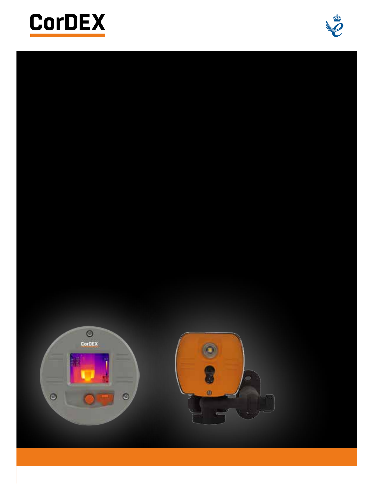
MN4000 & MN4100
SERIES THERMAL
IMAGING CAMERAS
RUGGED AUTHORITY
1.888.610.7664
www.ShopThermography.com
Page 2

CONTENTS
Introduction 8
Quick Start Guide 10
Mechanical Installation 12
Important Network Information & Parameters 13
Camera web server 14
CorDEX MONITIR software 15
MODBUS & HTML 15
IP Addressing 17
Factory Reset 17
CE Declaration of Conformity 17
Shop for Thermal Imaging products online at:
1.888.610.7664
www.ShopThermography.com
Page 3
REGISTER
YOUR
PRODUCT.
RUGGED AUTHORITY
Register your product now
at http://www.cord-ex.com/
register-your-product/ and
receive a 12 month extended
warranty.
Terms & Conditions apply.
OVERVIEW
The CorDEX Instruments, MN4xxx series
of continuous monitoring cameras offer an
affordable and accurate means of continuously
monitoring temperature either as a standalone
unit, or as part of a larger control system/
strategy.
The CorDEX MN4xxx camera platforms are
designed primarily with Industry Control &
Monitoring in mind and as such, are provided
with the industry standard communication
ability, MODBUS/TCP for communicating
with devices such as Programmable Logic
Controllers (PLCs).
The CorDEX MN4xxx may be installed in a
standalone or multi camera mode, with each
camera incorporating a built in web server for
basic setup purposes which is accessible via
a standard web browser using Ethernet/IP,
additional CorDEX PC Setup Software is also
available for download.
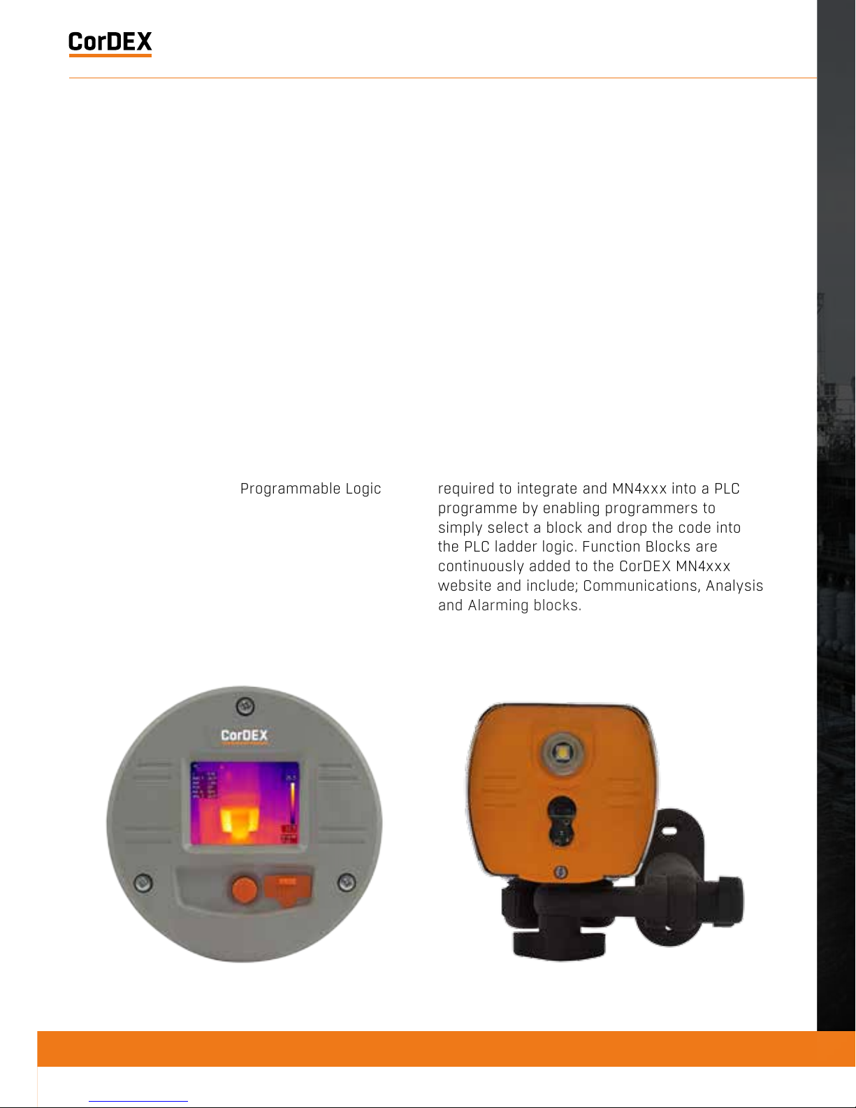
CorDEX MNxxx cameras are also supplied
with PLC Function Blocks for popular brands.
These prewritten code blocks are designed
to dramatically reduce the amount of time
required to integrate and MN4xxx into a PLC
programme by enabling programmers to
simply select a block and drop the code into
the PLC ladder logic. Function Blocks are
continuously added to the CorDEX MN4xxx
website and include; Communications, Analysis
and Alarming blocks.
RUGGED AUTHORITY
1.888.610.7664
www.ShopThermography.com
Page 4

REGISTER
YOUR
PRODUCT.
RUGGED AUTHORITY
Register your product now
at http://www.cord-ex.com/
register-your-product/ and
receive a 12 month extended
warranty.
Terms & Conditions apply.
Shop for Thermal Imaging products online at:
1.888.610.7664
www.ShopThermography.com
Page 5
1
Install the camera.
2
Download the CorDEX MONITIR PC Application from
www.cord-ex.com/products/monitir-software/
3
Connect power via the standard screwed terminal
block provided (11-20VDC).
MN4000 MN4100
4
Connect the camera to your PC using a USB
cable.
Connect the camera to your PLC using an Ethernet
cable.
5
Start the CorDEX MONITIR PC App.
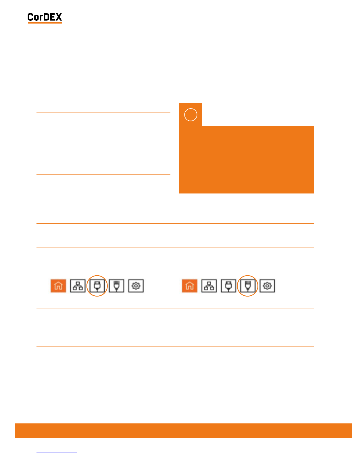
6
Select Direct Connect USB icon. Select Direct Connect Ethernet icon.
7
You have now accessed the CorDEX MN4000
series camera. From this screen you can setup
and provide basic control commands to the
camera.
Input the camera fixed static IP address
192.168.1.100 into the box and click Connect.
8
Click Submit. The camera will now restart with
desired settings.
You have now accessed the CorDEX MN4100 series
camera. From this screen you can setup and provide
basic control commands to the camera.
9
- Click Submit. The camera will now restart with
desired settings.
QUICK START GUIDE MECHANICAL INSTALLATION
MN4000
The CorDEX MN4000 panel mounted thermal
imager is intended for permanent installation
into electrical panels. Installation is achieved
in two stages.
Once the chassis has been installed, the
camera package can be removed and
replaced without shutting down or interrupting
the panel.
IMPORTANT NOTICE, MN4100
CAMERAS ARE SHIPPED WITH A
PREFIXED STATIC IP ADDRESS OF
192.168.1.100. This can be altered
using the CorDEX MONITIR PC App
(recommended).
1
Install the Chassis into the panel.
!
RUGGED AUTHORITY
1.888.610.7664
www.ShopThermography.com
Page 6
MN4000
The CorDEX MN4000 panel mounted thermal
imager is intended for permanent installation
into electrical panels. Installation is achieved
in two stages.
Once the chassis has been installed, the
camera package can be removed and
replaced without shutting down or interrupting
the panel.
1
Install the Chassis into the panel.
2
Attach the Camera Package to the chassis.
MONITIR Series Thermal Imaging Cameras – User Manual
7
Document Reference MONITIRSERIESUM Rev. A
Shop for Thermal Imaging products online at:
1.888.610.7664
www.ShopThermography.com
Page 7
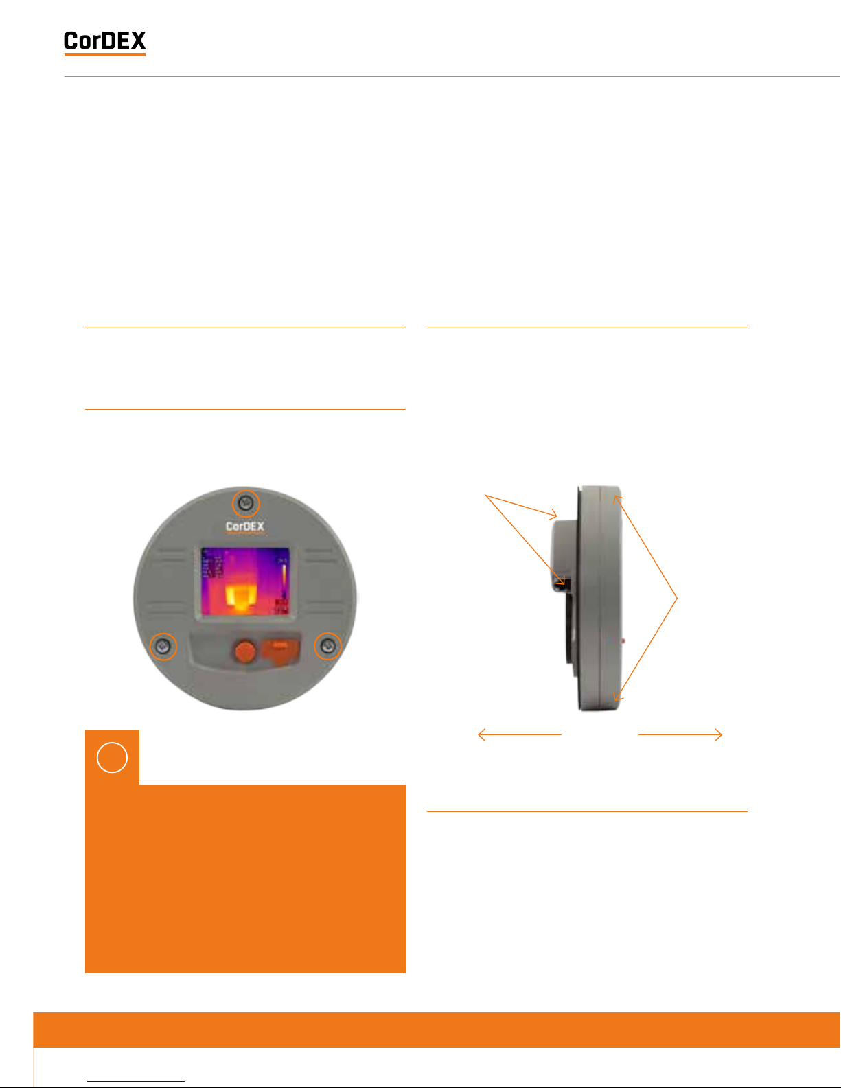
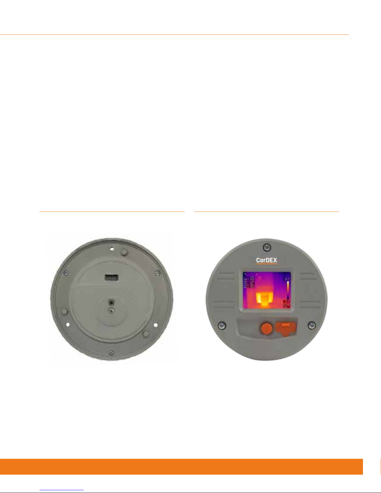
Installation of MN4000 Chassis
WARNING: Working on electrical equipment
presents significant risk and should only be
undertaken by suitably qualified personnel
in accordance with local applicable codes,
standards and corresponding Personal
Protective Equipment (PPE). This installation
procedure assumes a panel has been safely
removed and transported to a suitable location.
!
1
Remove the MN4000 from its packaging and place on
a flat surface, taking care not to scratch the lens.
2
Remove the three screws securing the Camera
Package to the Chassis.
3
Separate the Camera Package from the Chassis by
holding the Chassis communication bulge in one hand
and the Camera Package edge in the other hand then
gently but firmly pull apart.
4
Place the self-adhesive drilling template provided
into the desired location. Care should be taken to
ensure the rear of the panel is clear of ribs or other
obstructions prior to drilling.
5
Using the drill bit specified on the template (xxx), drill
the three fixing holes located around the perimeter.
6
Using an appropriate holes saw or punch, drill the
large (95mm/3¾”) centre hole.
7
Debur all rough edges and treat with rust inhibitor.
8
Align Chassis with mounting holes and attach using
three self-tapping screws provided, making sure to
advance the screws evenly.
Separate
Grip here
Grip here
RUGGED AUTHORITY
1.888.610.7664
www.ShopThermography.com
Page 8
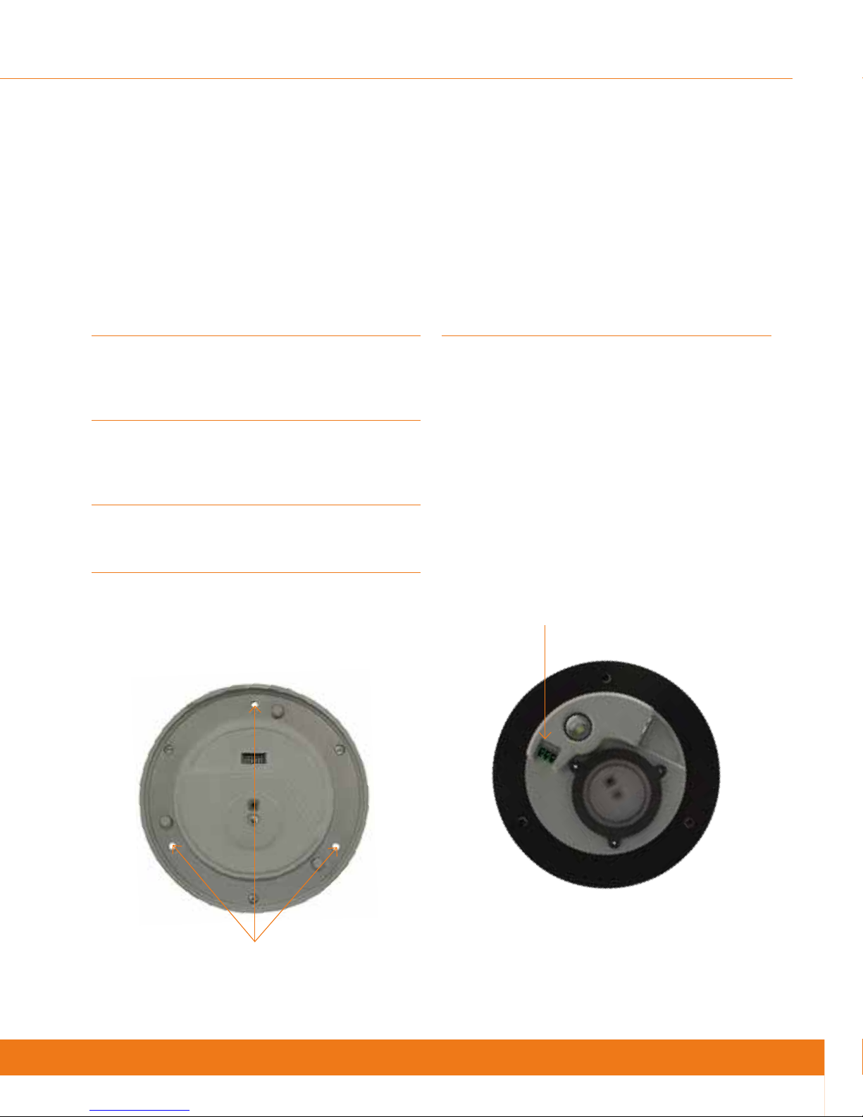
5
Using the drill bit specified on the template (xxx), drill
the three fixing holes located around the perimeter.
6
Using an appropriate holes saw or punch, drill the
large (95mm/3¾”) centre hole.
7
Debur all rough edges and treat with rust inhibitor.
8
Align Chassis with mounting holes and attach using
three self-tapping screws provided, making sure to
advance the screws evenly.
9
Connect 11-30VDC to the green power connector
(provided) and attached to Chassis. There are three
connections.
Top: 0V
Centre: Supplemental GND*
Bottom: +ve
*GND is a supplemental Ground connection. MN4000 Primary
Ground is via the RJ45 socket and communications line. If no
communications are installed, the Supplemental GND may
be connected in accordance with local Electrical Codes /
Regulatory Requirements.
Chassis mounting holes
Power connections here
MONITIR Series Thermal Imaging Cameras – User Manual
9
Document Reference MONITIRSERIESUM Rev. A
Shop for Thermal Imaging products online at:
1.888.610.7664
www.ShopThermography.com
Page 9
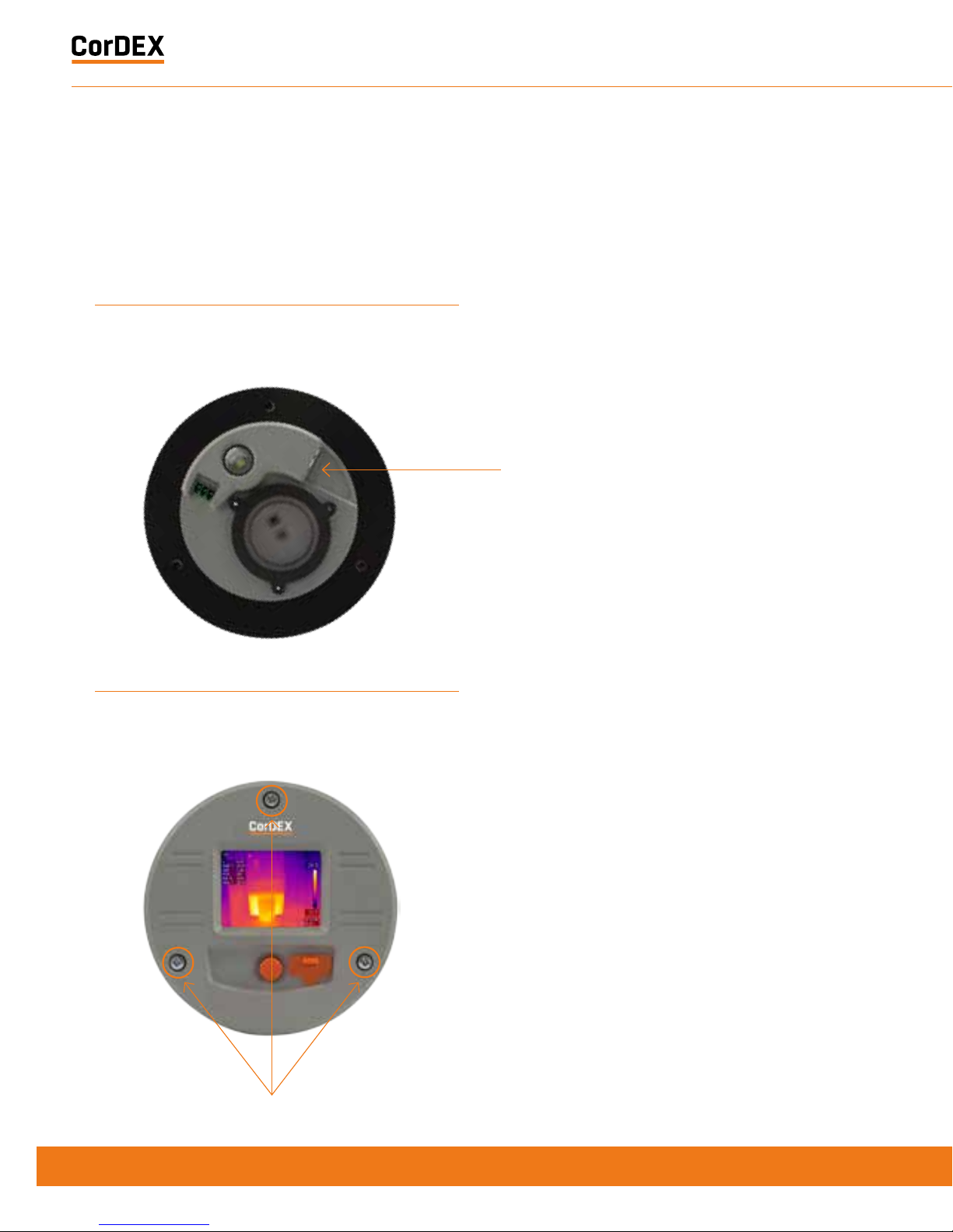
11
Replace the panel and secure before aligning the
Camera Package with the Chassis and fasten into
place with three fixing screws provided.
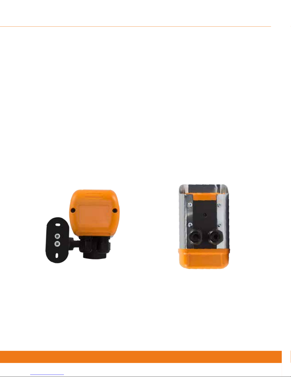
MN4100 attached to CDX8900-470
mounting arm.
Ethernet connection here
MN4100
The CorDEX MN4100 industrial automation
thermal imager is intended for permanent
installation into fixed locations for industrial
automation, control and safety monitoring
purposes. Installation is via an M6x4 threaded
boss located on the base of the camera
and optional mounting arm, part number
CDX8900-470 is also available.
10
If communications are to be used, connect an
Ethernet cable with RJ45 plug to Chassis.
Chassis mounting screws
RUGGED AUTHORITY
1.888.610.7664
www.ShopThermography.com
Page 10
MN4100 attached to CDX8900-470
mounting arm.
MN4100 Base showing M6x4 mounting
boss and two compression glands.
MN4100
The CorDEX MN4100 industrial automation
thermal imager is intended for permanent
installation into fixed locations for industrial
automation, control and safety monitoring
purposes. Installation is via an M6x4 threaded
boss located on the base of the camera
and optional mounting arm, part number
CDX8900-470 is also available.
MONITIR Series Thermal Imaging Cameras – User Manual
11
Document Reference MONITIRSERIESUM Rev. A
Shop for Thermal Imaging products online at:
1.888.610.7664
www.ShopThermography.com
Page 11

Installation of MN4100
This installation procedure assumes that
mechanical mounting and positioning has
already occurred, for specific mounting
instructions relating to CDX8900-470, please
view the MN4100 Mounting Arm Installation
Manual.
A typical industrial installation will comprise
of armoured cable for both power and
communications, terminating in a junction box
adjacent to the camera. Unarmoured power
and communications cables are run from the
junction box to the camera via the two M16
compression gland entries located in the
camera base.
Typical camera installation diagram
1
Remove rear weather cap from camera to expose
Ethernet socket and power terminals.
2
Insert power and communications cables into camera
via 2xM16 compression glands provided. NOTE, these
glands will accept cables with outside diameters from
3mm – 7mm.
3
Connect 11-30VDC to the green power connector
(provided) and attached to Chassis. There are three
connections
Top: 0V
Centre: Supplemental GND*
Bottom: +ve
*GND is a supplemental Ground connection. MN4000 Primary
Ground is via the RJ45 socket and communications line. If no
communications are installed, the Supplemental GND may
be connected in accordance with local Electrical Codes /
Regulatory Requirements.
4
Attached an RJ45 plug to the communications cable.
DO NOT PLUG INTO THE CAMERA AT THIS STAGE.
RUGGED AUTHORITY
1.888.610.7664
www.ShopThermography.com
Page 12

1
Remove rear weather cap from camera to expose
Ethernet socket and power terminals.
2
Insert power and communications cables into camera
via 2xM16 compression glands provided. NOTE, these
glands will accept cables with outside diameters from
3mm – 7mm.
3
Connect 11-30VDC to the green power connector
(provided) and attached to Chassis. There are three
connections
Top: 0V
Centre: Supplemental GND*
Bottom: +ve
*GND is a supplemental Ground connection. MN4000 Primary
Ground is via the RJ45 socket and communications line. If no
communications are installed, the Supplemental GND may
be connected in accordance with local Electrical Codes /
Regulatory Requirements.
4
Attached an RJ45 plug to the communications cable.
DO NOT PLUG INTO THE CAMERA AT THIS STAGE.
Power connector
RJ45 Socket
Compression glands
MONITIR Series Thermal Imaging Cameras – User Manual
13
Document Reference MONITIRSERIESUM Rev. A
Shop for Thermal Imaging products online at:
1.888.610.7664
www.ShopThermography.com
Page 13

5
Connect camera to a PC running CorDEX MONITIR
software, select Direct Connection, Ethernet and
use the default address 192.168.1.100. You can now
configure the camera for your network, for more
information on CorDEX MONITIR Application, please
refer to the specific software user manual.
6
Once the camera has been locally configured for your
network, attach the RJ45 connector and replace the
weather cover.
7
The camera is now ready for use.
NETWORK INFORMATION
AND PARAMETERS
RUGGED AUTHORITY
1.888.610.7664
www.ShopThermography.com
Page 14

NETWORK INFORMATION
AND PARAMETERS
IMPORTANT NOTICE
CorDEX MN4000 cameras are shipped as DHCP enabled as setup configuration is via the
USB port located on the front of the camera.
CorDEX MN4100 cameras are shipped with a STATIC IP ADDRESS of 192.168.1.100 This is
the default address the CorDEX MONITIR PC Application uses in Direct Ethernet Connect
mode when communicating with the camera during initial setup.
Please refer to your Network Administrator and obtain the correct parameters before
connecting MN4xxx cameras to your network.
MONITIR Series Thermal Imaging Cameras – User Manual
15
Document Reference MONITIRSERIESUM Rev. A
Shop for Thermal Imaging products online at:
1.888.610.7664
www.ShopThermography.com
Page 15

CAMERA WEB
SERVER INTERFACE
EACH CORDEX MN4XXX CAMERA IS SUPPLIED WITH AN ONBOARD WEB INTERFACE.
Accessing the web interface
To access the web interface, open your
internet browser and in the address bar type
the IP Address of the camera you wish to
communicate with.
The speed of the network connection will
determine the rate at which the camera
responds.
The image shown is a snapshot and not a live
feed, to reload an image, click Refresh Image.
Thermal data is captured and made available
for machine vision/automation at a frequency
of 9Hz.
Home tab
The Home tab is the default tab after logging
into the camera. Under the Home tab, it is
possible to change the image type, image
colourisation, set rising and falling isotherms
and to toggle the onboard LED.
IP Address
Image type Example image
Highlight
Combines v isual and thermal images into one with the
hottest areas bleeding through the visual.
Visible only
The visible image captured by the 640x480 onboard
digital camera.
Selecting the correct Image Type
The camera captures both visual and thermal
images simultaneously, your choice of Image
Type determines which of four options are
displayed on the screen.
RUGGED AUTHORITY
1.888.610.7664
www.ShopThermography.com
Page 16

Image type Example image
Highlight
Combines v isual and thermal images into one with the
hottest areas bleeding through the visual.
Visible only
The visible image captured by the 640x480 onboard
digital camera.
Selecting the correct Image Type
The camera captures both visual and thermal
images simultaneously, your choice of Image
Type determines which of four options are
displayed on the screen.
MONITIR Series Thermal Imaging Cameras – User Manual
17
Document Reference MONITIRSERIESUM Rev. A
Shop for Thermal Imaging products online at:
1.888.610.7664
www.ShopThermography.com
Page 17

Thermal only
The thermal image captured by the 80x60 infrared
camera. Due to the resolution of the infrared camera
alone, this mode is not recommended for scenes with a
low dynamic temperature range.
Isotherm overlay
When a rising and/or falling isotherm is configured and
Isotherm overlay selected, the areas w hich fall into
the Isotherm alarm condition are coloured and shown
on the image. This example has both rising and falling
isother ms configured. T he rising isotherm is show n in
red/orange, the falling isotherm is show in purple.
To select an Image Type, click the drop down
box and select the desired option, then click
the Send to Camera button. The command will
be transmitted to the camera and the image
refreshed after a few moments with your new
settings applied.
Setting Rising/Falling Isotherms
An Isotherm is an alarm condition where a
temperature level which is above (rising) or
below (falling) the Isotherm setpoint causes
the image in that set location to be highlighted
on the visual image by means of a colour.
To Set a Rising Isotherm, click the OFF/ON
toggle switch to the ON position (green) and
insert the alarm value in the box adjacent to
the button.
Click “Send to Camera”.
Any temperature in the cameras Field of View
(FOV) above this temperature will be coloured.
To Set a Falling Isotherm, click the OFF/ON
toggle switch to the ON position (green) and
insert the alarm value in the box adjacent to
the button.
Click “Send to Camera”.
Any temperature in the cameras Field of View
(FOV) below this temperature will be coloured.
It is possible to set both Rising and
Falling Isotherms on the same camera
simultaneously.
RUGGED AUTHORITY
1.888.610.7664
www.ShopThermography.com
Page 18

Setting Rising/Falling Isotherms
An Isotherm is an alarm condition where a
temperature level which is above (rising) or
below (falling) the Isotherm setpoint causes
the image in that set location to be highlighted
on the visual image by means of a colour.
To Set a Rising Isotherm, click the OFF/ON
toggle switch to the ON position (green) and
insert the alarm value in the box adjacent to
the button.
Click “Send to Camera”.
Any temperature in the cameras Field of View
(FOV) above this temperature will be coloured.
To Set a Falling Isotherm, click the OFF/ON
toggle switch to the ON position (green) and
insert the alarm value in the box adjacent to
the button.
Click “Send to Camera”.
Any temperature in the cameras Field of View
(FOV) below this temperature will be coloured.
It is possible to set both Rising and
Falling Isotherms on the same camera
simultaneously.
Toggling the onboard LED illuminator
The camera is equipped with an onboard LED
illuminator for extremely low light situations.
To toggle the LED illuminator, click the LED
OFF/ON button and then click the Send to
Camera button.
Spot temperatures
The camera has three spot temperature
points; Hot, Cold and Dynamic.
The Hot temperature identifier puts a red
cross on the hottest part of the image.
The Cold temperature identifier puts a blue
cross on the coldest par t of the image.
The Dynamic temperature measurement
shows the temperature of the cursor in the
Spot Temperature box.
MODBUS Registers & Coordinates
When Configuring Programmable Logic
Controllers (PLCs) to perform actions based
upon MN4xxx measurements, it is necessary
to be able to define either the MODBUS
Register of a particular point in the image
and/or its x,y coordinates.
To do this, hover the mouse over the point
on the image you are interested in and the
MODBUS Reg will be shown in the Modbus
Reg field, in brackets, the x,y coordinates for
the same MODBUS Register are shown.
MONITIR Series Thermal Imaging Cameras – User Manual
19
Document Reference MONITIRSERIESUM Rev. A
Shop for Thermal Imaging products online at:
1.888.610.7664
www.ShopThermography.com
Page 19

Alarm Tab
The Alarm tab opens the grid alarm page of
the MN4xxx webserver. Each MN4xxx camera
can accommodate a 5x5 grid square with a
configurable rising alarm in each square.
When a grid squares maximum temperature
exceeds its alarm threshold the alarm bell
notification on the home page activates and
a specific register in the MODBUS table is
toggled.
Setting a grid alarm
To set a grid alarm, click the grid square of
interest and the alarm setup box will appear.
Select ON from the Alarm OFF/ON toggle and
enter the Rising Isotherm alarm value. Then
click Update, followed by Submit.
The grid square alarm is now active and can
be monitored using a PLC to check for the
MODBUS Register bit associated with that
specific grid. For more information, see page
26, MODBUS & HTML.
Settings
The Settings tab allows users to configure
the camera Location Name, the units of
measurement and network setup information.
The Location Name is a unique identifier input
by the installer which pinpoints the camera
location, once set, this should not be changed
unless the camera duty is altered.
The unit of measure can be selected from
three potential options; Celcius, Fahrenheit
and Kelvin.
DHCP Server enable, Ip Address, Subnet Mask
and Gateway can all be manually configured in
the Settings tab.
Once complete, click Apply and the settings
will be transmitted to the camera.
RUGGED AUTHORITY
1.888.610.7664
www.ShopThermography.com
Page 20

Settings
The Settings tab allows users to configure
the camera Location Name, the units of
measurement and network setup information.
The Location Name is a unique identifier input
by the installer which pinpoints the camera
location, once set, this should not be changed
unless the camera duty is altered.
The unit of measure can be selected from
three potential options; Celcius, Fahrenheit
and Kelvin.
DHCP Server enable, Ip Address, Subnet Mask
and Gateway can all be manually configured in
the Settings tab.
Once complete, click Apply and the settings
will be transmitted to the camera.
CorDEX MONITIR Software
The CorDEX MN4xxx series cameras are
intended for installations of all sizes; from a
single camera, to hundreds. For large scale
installations, determining one camera from
another on a network becomes problematic
To overcome this CorDEX have developed
CorDEX MONITIR PC Application.
MONITIR is an expandable application, initially
used to setup one or more cameras as part
of the installation process. Once installation
is complete, MONITIR can then be used
to access every camera on the network
remotely.
To download the CorDEX MONITIR Software,
please visit www.cord-ex.com/products/
monitir-software/
MONITIR Series Thermal Imaging Cameras – User Manual
21
Document Reference MONITIRSERIESUM Rev. A
Shop for Thermal Imaging products online at:
1.888.610.7664
www.ShopThermography.com
Page 21

Homepage
The CorDEX MONITIR PC Application is
intended for setup purposes both of a
standalone camera and also to aid PLC
Integration.
The Application is broken down into two
main methods of communication; Network
Discovery and Direct Connect.
Network
Discovery
Settings
Direct Connect
(USB)
Direct Connect
(Ethernet)
Network Discovery
Net work Discover is intended to identif y
all CorDEX MN4xxx cameras located on a
net work. This is achieved by broadcasting a
message across the net work, to which each
camera responds providing;
1. Instrument Type – This refers to camera
type (Factory set)
2. Location – This is a description,
uploaded to the camera during initial
installation/setup, that provides a
means of identifying where the camera
is located in a particular facilit y. (User
configurable)
3. Ip Address – The IP Address of the
camera (User configurable)
4. Mac Address – The Mac Address of the
camera (Factor y set)
5. Serial Number – The Serial Number of
the camera (Factory set)
RUGGED AUTHORITY
1.888.610.7664
www.ShopThermography.com
Page 22

Network Discovery
Net work Discover is intended to identif y
all CorDEX MN4xxx cameras located on a
net work. This is achieved by broadcasting a
message across the net work, to which each
camera responds providing;
1. Instrument Type – This refers to camera
type (Factory set)
2. Location – This is a description,
uploaded to the camera during initial
installation/setup, that provides a
means of identifying where the camera
is located in a particular facilit y. (User
configurable)
3. Ip Address – The IP Address of the
camera (User configurable)
4. Mac Address – The Mac Address of the
camera (Factor y set)
5. Serial Number – The Serial Number of
the camera (Factory set)
To deploy Network Discover y from the
homepage, ensure the PC running MONITIR
is connected to the same network as the
MN4xxx cameras and click the Network
Discovery icon, the Network Discover y page
will appear and the user prompted to begin
the Discovery process.
Once complete, the window will be populated
with all the cameras which have responded to
the Network Discovery broadcast message.
Double clicking on a particular camera will
open the corresponding setup page, this is the
same page as Direct Connect Ethernet.
MONITIR Series Thermal Imaging Cameras – User Manual
23
Document Reference MONITIRSERIESUM Rev. A
Shop for Thermal Imaging products online at:
1.888.610.7664
www.ShopThermography.com
Page 23

Direct Connect (USB)
MN4000 Cameras can be configured via the
chassis in Direct Connect Ethernet mode or
when installed and in use, via Direct Connect
USB mode, this is the recommended mode of
communication for initial setup.
To communicate via Direct Connect USB, first
ensure the MN4000 is powered up and the
PC running MONITIR Application is connected
to the USB port located on the front of the
camera.
Direct Connect (Ethernet)
Both MN4000 and MN4100 have the capability
for a direct, PC to Camera Ethernet connection
using the MONITIR PC Application. Direct
Connect (Ethernet) is the recommended initial
setup mode for MN4100 cameras as they are
shipped with a factory set static IP address.
To communicate with the camera, ensure
the PC running the MONITIR Application is
connected to the camera with an Ethernet
cable, then click the Direct Connect (Ethernet)
icon from the homepage.
Then click the Direct Connect (USB) icon
from the home screen and the Application
will communicate directly with the camera,
displaying returned data in the following
format.
RUGGED AUTHORITY
1.888.610.7664
www.ShopThermography.com
Page 24

Direct Connect (Ethernet)
Both MN4000 and MN4100 have the capability
for a direct, PC to Camera Ethernet connection
using the MONITIR PC Application. Direct
Connect (Ethernet) is the recommended initial
setup mode for MN4100 cameras as they are
shipped with a factory set static IP address.
To communicate with the camera, ensure
the PC running the MONITIR Application is
connected to the camera with an Ethernet
cable, then click the Direct Connect (Ethernet)
icon from the homepage.
If this is a first time setup of an MN4000, type
192.168.1.100 into the Ip address box and click
Connect. If this is not a first time setup, you
must type the Ip address associated with your
specific camera.
MONITIR Series Thermal Imaging Cameras – User Manual
25
Document Reference MONITIRSERIESUM Rev. A
Shop for Thermal Imaging products online at:
1.888.610.7664
www.ShopThermography.com
Page 25

MODBUS & HTML
The MN4000 and MN4100 have Modbus
TCP and HTML access for mage display and
analysis.
MODBUS/TCP
The Modbus protocol used is Modbus TCP/
IP also known as Modbus TCP. http://w ww.
modbus.org/docs/Modbus_Messaging_
Implementation_Guide_V1_0b.pdf
Following Modbus command function codes
are used:
• Function code 3: Read Multiple Registers
• Function code 4: Read Input Registers
• Function code 6: Write Single Registers
• Function code 16: Write Multiple Registers
Modbus TCP/IP connects over TCP/IP
net works using por t 502. A checksum is
not required as a checksum calculation
implemented in the lower layers already
provides checksum protection. The frames do
not include a checksum.
On TCP/IP the Modbus server is addressed
using its IP address. The Modbus Unit
Identifier is set to 0FFh.
Register Access: Code 4
The MN4xxx cameras implement Modbus
TCP command function code 4 “Read Input
Registers” (16 bit), with the addresses as
defined in the following table.
MODBUS Function Code 4 TCP registers
* MODBUS access is big-endian
** To convert to Fahrenheit= (cK*9)/5-45967,
Celcius=(cK-27315)/100
Register Access: code 3, 6, 16
The MN4xxx cameras implement Modbus TCP
command function codes 3, 6 and 16 with the
addresses as defined in the following table.
MODBUS Function code 3, 6, 16 TCP Registers
Address*
Function Code: 4 Comment
0 to 4799
Sensor temperature
array, 80x60
Units: cK
(ccentikelvin**)
Global
constants:
Emissivity =1
0= Top LHS,
4799= Bottom
RHS
4800
AlarmBit [24:16]
for each bit
1: alarmed
0: no alarm
Corresponds
to 25 grid
alarm limits.
Alarm for
any pixel >T
set
4801
AlarmBit [15:0] for
each bit
1: alarmed
0: no alarm
Corresponds
to 25 grid
alarm limits.
Alarm for
any pixel >T
set
Address*
0 to 24
Address*
0 to 24
RUGGED AUTHORITY
1.888.610.7664
www.ShopThermography.com
Page 26

Register Access: code 3, 6, 16
The MN4xxx cameras implement Modbus TCP
command function codes 3, 6 and 16 with the
addresses as defined in the following table.
MODBUS Function code 3, 6, 16 TCP Registers
HTML Browser
A web browser may be used to setup
all aspects of the camera operation, the
recommended browser is Chrome.
HT TP browser access can be used to
access camera data structures by software
integrators as follows:
• http:IP-address/vis.jpg visible image jpeg
• http:IP-address/ir.bmp IR image
• http:IP-address/raw.bin IR temperature
array, 80 x 60 x 16bit
• http:IP-address/lep.bin IR info
• http:IP-address/alarm.bin alarm settings,
5 x 5 x 16bit
• http:IP-address/firmware.html prompts for
binary file then reboots 10s after upload
Address*
Function Code;
3, 6, 16
Comment
0 to 24
Sensor alarm array,
5x5
Units: cK (centikelvin)
0=Top LHS,
14=Bottom RHS
Address*
Function Code;
3, 6, 16
Comment
0 to 24
Sensor alarm array,
5x5
Units: cK (centikelvin)
0=Top LHS,
14=Bottom RHS
MONITIR Series Thermal Imaging Cameras – User Manual
27
Document Reference MONITIRSERIESUM Rev. A
Shop for Thermal Imaging products online at:
1.888.610.7664
www.ShopThermography.com
Page 27

HTML Access (Settings page)
The setting page information is accessed
using a HTTP GET.
The webserver is not capable of Server Side
Includes. Instead all data on the page is
populated from a binary file loaded from the
ser ver using javascript. The offsets within the
binary file are as shown in the javascript.
The form submit has parameters:
• t= as session token
• cfk= as the units
(0:Celcius/1:Farentheit/2:Kelvin)
• loc= as the location text field
• ethIpAddress= as the static IP in decimal
• ethSubnetMask= as the static subnet
mask in decimal
• ethGateway= as the static gateway in
decimal
• dhcp= as the (0:DHCP/1:Static IP)
An example implementation is as follows:
Reading
HT TP GET /lep.bin returns a binary file. In the
javascript this is converted to an unsigned 16
bit array s[].
Where
• cfk is at s[8+2*176+5];
• dhcp is at s[8+2*176+25]; upper 8 bits
• loc is at s[8+2*176+8]; nex t 16 characters
• ethIpAddress is at s[8+2*176+26]; next 4
bytes
• ethSubnetMask is at s[8+2*176+28]; next 4
bytes
• ethGateway is at s[8+2*176+30]; next 4
bytes
• token t is at s[8+2*176+34+4];
Setting
HTTP GET /eth.ccgi?&t=1234&cfk=0&loc=
cordex&dhcp=1ðIpAddress=1234ð
SubnetMask=1234ðGateway=1234
Note on units for web browser access
All temperature values sent to camera are in
the current units format (C, F, K).
All temperatures returned from the camera are
in centikelvin. This is due to limitations in the
HTML implementation.
Any writes that change the DHCP, IP address,
Netmask, or Gateway configuration will also
cause a reboot a few seconds later. This is
required as the Ethernet stack needs to be
restarted in this situation.
Applies to both the eth.cgi and the USB.
RUGGED AUTHORITY
1.888.610.7664
www.ShopThermography.com
Page 28

Setting
HTTP GET /eth.ccgi?&t=1234&cfk=0&loc=
cordex&dhcp=1ðIpAddress=1234ð
SubnetMask=1234ðGateway=1234
Note on units for web browser access
All temperature values sent to camera are in
the current units format (C, F, K).
All temperatures returned from the camera are
in centikelvin. This is due to limitations in the
HTML implementation.
Any writes that change the DHCP, IP address,
Netmask, or Gateway configuration will also
cause a reboot a few seconds later. This is
required as the Ethernet stack needs to be
restarted in this situation.
Applies to both the eth.cgi and the USB.
MONITIR Series Thermal Imaging Cameras – User Manual
29
Document Reference MONITIRSERIESUM Rev. A
Shop for Thermal Imaging products online at:
1.888.610.7664
www.ShopThermography.com
Page 29

HTML Access (IR data structure)
The structure for the IR information:
typedef struct lepton_settings_struct
{
__packed uint16_t isotherm_min_enable;
__packed uint16_t isotherm_max_enable;
__packed uint16_t isotherm_min;
__packed uint16_t isotherm_max;
__packed uint16_t palette;
__packed uint16_t units;
__packed uint16_t led;
__packed uint16_t reserved1;
__packed char name[16];
__packed char serial[STRING_LENGTH];
__packed enum View_Mode view_mode;
__packed enum DateFormat date_format;
__packed enum TimeFormat time_format;
__packed enum Dhcp dhcp;
__packed uint32_t static_ip_addr;
__packed uint32_t static_netmask;
__packed uint32_t static_gateway;
__packed uint32_t crc;
} lepton_settings_type;
typedef struct lepton_info_struct
{
__packed uint16_t bin_max;
__packed uint16_t bin_min;
__packed uint16_t max_x;
__packed uint16_t max_y;
__packed uint16_t min_x;
__packed uint16_t min_y;
__packed uint16_t palette_depth;
__packed int16_t ambient;
__packed uint16_t palette_lut[PALETTE_
LARGEST];
__packed uint16_t palette_temp[PALETTE_
LARGEST];
__packed lepton_settings_type settings;
__packed uint32_t firmware;
__packed uint32_t alarm_status;
__packed uint16_t token;
} lepton_info_type;
typedef struct alarm_settings_struct
{
__packed uint16_t alarm[25];
__packed uint32_t alarm_enable;
__packed uint16_t token;
} alarm_settings_type;
enum Palette { GREY_POSITIVE=0, GREY_
NEGATIVE, IRON, HOTMETAL, RAINBOW, AMBER,
SEPIA };
enum View_Mode { ISOTHERM_OVERLAY,
THERMAL_ONLY, VISIBLE_ONLY, HIGHLIGHT,
MAX_VIEW_MODE };
enum Units { CELSIUS, FARENHEIT, KELVIN,
MAX_UNITS };
enum DateFormat { YYYYMMDD, DDMMYYYY,
MMDDYYYY, MAX_DATE_FORMAT };
enum TimeFormat { HH24MMSS, HH12MMSS,
MAX_TIME_FORMAT};
enum Dhcp { DHCP, STATIC_IP, MAX_DHCP};
enum Led { LED_DISABLED, LED_ENABLED,
MAX_LED};
DateFormat and TimeFormat are not used.
palette_lut[PALETTE_LARGEST] is an array of
colors
Colours are RGB565, 16 bit colour.
palette_temp[PALETTE_LARGEST] is an array
of temperatures in cK
The temperatures of each palette colour.
RUGGED AUTHORITY
1.888.610.7664
www.ShopThermography.com
Page 30

enum Palette { GREY_POSITIVE=0, GREY_
NEGATIVE, IRON, HOTMETAL, RAINBOW, AMBER,
SEPIA };
enum View_Mode { ISOTHERM_OVERLAY,
THERMAL_ONLY, VISIBLE_ONLY, HIGHLIGHT,
MAX_VIEW_MODE };
enum Units { CELSIUS, FARENHEIT, KELVIN,
MAX_UNITS };
enum DateFormat { YYYYMMDD, DDMMYYYY,
MMDDYYYY, MAX_DATE_FORMAT };
enum TimeFormat { HH24MMSS, HH12MMSS,
MAX_TIME_FORMAT};
enum Dhcp { DHCP, STATIC_IP, MAX_DHCP};
enum Led { LED_DISABLED, LED_ENABLED,
MAX_LED};
DateFormat and TimeFormat are not used.
palette_lut[PALETTE_LARGEST] is an array of
colors
Colours are RGB565, 16 bit colour.
palette_temp[PALETTE_LARGEST] is an array
of temperatures in cK
The temperatures of each palette colour.
MONITIR Series Thermal Imaging Cameras – User Manual
31
Document Reference MONITIRSERIESUM Rev. A
Shop for Thermal Imaging products online at:
1.888.610.7664
www.ShopThermography.com
Page 31

Window Coordinate Conversions
For user co-ordinates, the top LHS is
considered to be location (x=0, y=0)
Fig 11.5 Pixel x,y coordinates and Modbus registers
USB Commands
The USB commands available to MN4xxx
cameras are as follows:
USB_MAC_ADDRESS, USB_ISOMINEN,
USB_ISOMAXEN, USB_ISOMIN,
USB_ISOMAX, USB_PALETTE, USB_UNITS,
USB_LED, USB_NAME, USB_SERIALNUM,
USB_VIEWMODE, USB_DHCP, USB_IP_ADDRESS,
USB_NETMASK, USB_GATEWAY, USB_ALARM
This command set is sufficient setup a MN4xxx
via USB prior to placing on the IP network.
IP Addressing
IP Address Allocation
This section describes the following:
• IP address allocation and discovery for
MN4100 which doesn’t have a display
(also can be used for MN4000)
• Networks without a DHCP server will
default to an IP address which can then
be set to a static IP address
The Following methods are used for IP address
allocation:
• Auto-Find: IP discovery program returns
the IP address allocated by the DHCP
server to each AW
• Manual configuration of static IP address
• Default static IP address (192.168.1.100)
The cameras will be shipped with following IP
address allocation as default
• MN4000 ship with DHCP Enabled
(non-static address),
• MN4100 Ship with static IP address of
192.168.1.100
Ip Address Discovery (Auto-Find IP)
The units use the network DHCP server to
assign IP addresses. A discovery program is
used to return the local unit IP addresses.
For the case where there is no DHCP server
the unit will default to IP address 169.254.xx.xx,
where xx.xx is a randomly generated number.
The camera verifies this default IP address is
unique in the local network.
The auto-find will return this address.
RUGGED AUTHORITY
1.888.610.7664
www.ShopThermography.com
Page 32

Ip Address Discovery (Auto-Find IP)
The units use the network DHCP server to
assign IP addresses. A discovery program is
used to return the local unit IP addresses.
For the case where there is no DHCP server
the unit will default to IP address 169.254.xx.xx,
where xx.xx is a randomly generated number.
The camera verifies this default IP address is
unique in the local network.
The auto-find will return this address.
Camera Identification (Host Name)
An auto-find is implemented using UDP
broadcast on port 46000 containing “MonitIR?”
The host name field that appears in the router
table is as follows:
• Auto-configured as Monitir_<processorU
ID>. The processorUID is a 64-bit number
• The DHCP client returns a hostname of
“MonitIR-“+(unique serial number)
• This can be used to identify any camera
in the table and will appear in the
broadcast response
• This can also be used with a unicast
address to obtain the same response
Information in the broadcast response is as
follows:
• Serial number: “Monitir”+(unique serial
number)
• MAC address
• Location ID (text)
• Instrument identification
MONITIR Series Thermal Imaging Cameras – User Manual
33
Document Reference MONITIRSERIESUM Rev. A
Shop for Thermal Imaging products online at:
1.888.610.7664
www.ShopThermography.com
Page 33

Auto-Find Example
The example has a button and a list box as
follows:
• When the button is clicked function
button1_Click() is called that sends a UDP
broadcast on port 46000 containing
“MonitIR?”.
• The list box is populated with the replies
contents
This could be rejigged to suit a multithreading
app by using non-blocking calls instead of
using the ReceiveTimeout.
// MonitIRfinder note the changed offsets
within ServerResponseData
using System;
using System.Collections.Generic;
using System.ComponentModel;
using System.Data;
using System.Drawing;
using System.Linq;
using System.Text;
using System.Threading.Tasks;
using System.Windows.Forms;
using System.Net;
using System.Net.Sockets;
namespace MonitIRfind
{
public partial class MonitIRfinder : Form
{
public MonitIRfinder()
{
InitializeComponent();
}
private void button1_Click(object sender,
EventArgs e)
{
var client = new UdpClient();
var RequestData = Encoding.ASCII.
GetBytes(“MonitIR?”);
var ServerEp = new IPEndPoint(IPAddress.
Any, 0);
client.EnableBroadcast = true;
client.Client.ReceiveTimeout = 3000;
listBox1.Items.Clear();
// send data: “MonitIR?”
client.Send(RequestData, RequestData.Length,
new IPEndPoint(IPAddress.Broadcast, 46000));
// then receive data
while (true)
{
try
{
var ServerResponseData = client.
Receive(ref ServerEp);
var ServerResponse = Encoding.ASCII.Get-
String(ServerResponseData).Substring(0, 24);
var ServerVer = “”;
var ServerMac = “”;
var ServerLocation = “”;
if (ServerResponseData.Length > 25)
RUGGED AUTHORITY
1.888.610.7664
www.ShopThermography.com
Page 34

InitializeComponent();
}
private void button1_Click(object sender,
EventArgs e)
{
var client = new UdpClient();
var RequestData = Encoding.ASCII.
GetBytes(“MonitIR?”);
var ServerEp = new IPEndPoint(IPAddress.
Any, 0);
client.EnableBroadcast = true;
client.Client.ReceiveTimeout = 3000;
listBox1.Items.Clear();
// send data: “MonitIR?”
client.Send(RequestData, RequestData.Length,
new IPEndPoint(IPAddress.Broadcast, 46000));
// then receive data
while (true)
{
try
{
var ServerResponseData = client.
Receive(ref ServerEp);
var ServerResponse = Encoding.ASCII.GetString(ServerResponseData).Substring(0, 24);
var ServerVer = “”;
var ServerMac = “”;
var ServerLocation = “”;
if (ServerResponseData.Length > 25)
{
ServerVer = ServerResponseData[25].
ToString();
ServerMac = BitConverter.ToString(ServerRe
sponseData.Skip(26).Take(6).ToArray());
ServerLocation = Encoding.ASCII.GetString(
ServerResponseData).Substring(32, 16);
}
listBox1.BeginUpdate();
listBox1.Items.Add(ServerResponse + “ at “ +
ServerEp.Address.ToString() + “ Ver: “ + ServerVer + “ MAC: “ + ServerMac + “ Location: “ +
ServerLocation);
listBox1.EndUpdate();
}
catch (Exception exc) { break; }
}
client.Close();
}
}
}
Parse the response as follows
Bytes[0..24] = “MonitIR-“+serial_number,
bytes[25] = hardware_version, bytes[26..31] =
mac address, bytes[32..47] = location
Hardware version identifies the units as
MN4000 / MN4100 and reflects hardware
defined signals.
The hardware signals are PB[15:14] copied as
HWVersion[1:0]
MONITIR Series Thermal Imaging Cameras – User Manual
35
Document Reference MONITIRSERIESUM Rev. A
Shop for Thermal Imaging products online at:
1.888.610.7664
www.ShopThermography.com
Page 35

Factory Reset
MN4100 has a Factory Reset function which
erases all user configured settings/data and
returns the unit to it original factor y setup.
MN4000 Factory reset
The MN4000 has no Factory Reset as all
parameters are available locally at the
camera.
MN4100 Factory reset
The MN4100 Factory Reset is achieved by
pressing and holding the Factory Reset button
located at the rear of the camera for one
second.
PB[15:14}
HWVersion[1:0]
PB[15:14} = HWVersion [1:0]
defines unit ID
00 = MN4100 (no LCD)
01= MN4000 (with LCD)
RUGGED AUTHORITY
1.888.610.7664
www.ShopThermography.com
Page 36

RUGGED AUTHORITY
Revision A
MONITIR Series Thermal Imaging Cameras – User Manual
37
Document Reference MONITIRSERIESUM Rev. A
Shop for Thermal Imaging products online at:
1.888.610.7664
www.ShopThermography.com
 Loading...