

Page 1

QUICKGUIDE TO
SYSTEM 2
ACCESS CONTROL
INSTALLATION
access control
systems
Page 2
QUICKGUIDE TO ACCESS CONTROL INSTALLATION
System 2
n
Networks up to 16 doors
n
Each unit Supports 485 users
n
Add up to 6,000 users later
n
Start with one Door now, add more later
n
Built-in programming or use your PC
n
Easy off-site set-up & reporting
n
Reliable distributed system
n
Built-in printer output
Model 2003
One Door Control
access control
systems
n
One door access control
n
Supports one card reader and one keypad
n
Battery Backup: 4 Amp/hr for 15 hours of backup time
n
Power Requirements: 16.5VAC @ 40VA transformer with standby battery
n
Supports Bar Code, Data Chip, Mag-Stripe, Proximity and Wiegand card technologies
n
Memory Backup: 3 VDC lithium battery for a minimum of 30 days memory backup
n
One Door Relay: Form C and Form A contact rated 5A @ 30 VDC
n
One Auxiliary Relay: Form C contact rated 5A @ 30 VDC
n
One Voltage Output: Switches low (-) 50 ma
n
One Sh unt Contact and One Zone Input
n 26/30-bit Wiegand card formats
Model 2016
Two Door Control
n
Two door access control
n
Supports two card readers and two keypads
n
Battery Backup: 4 Amp/hr for 15 hours of backup time
n
Power Requirements: 16.5VAC @ 40VA transformer with standby battery
n
Supports Bar Code, Data Chip, Mag-Stripe, Proximity and Wiegand card technologies
n
Memory Backup: 3 VDC lithium battery for a minimum of 30 days memory backup
n
Two Door Relays: Form C and Form A contact rated 5A @ 30 VDC
n
Two Auxiliary Relays: Form C contact rated 5A @ 30 VDC
n
Two Voltage Outputs: Switches low (-) 50 ma
n
Two Shunt Contacts and Two Zone Inputs
n 26/30-bit Wiegand card formats
For further assistance, call (800) OK CORBY
Page 3
QUICKGUIDE TO ACCESS CONTROL INSTALLATION
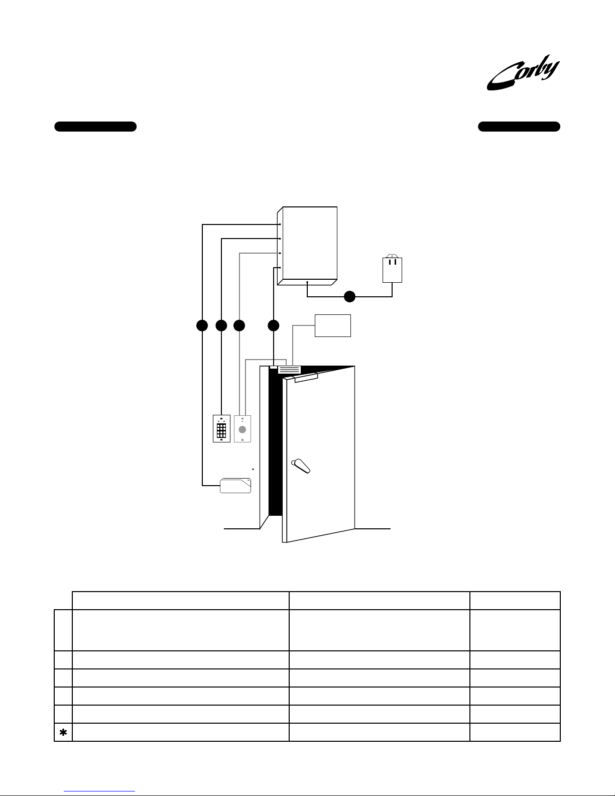
System 2 - Model 2003
One Door Control
Model 2003
16.5
VAC
40VA
E
access control
systems
A B C D
CONTACT
PUSH TO EXIT
2 3
1
5 6
4
9
7 8
0
#
*
OUT RTE
IN Keypad
and/or
IN Card Reader
Corby Card
If using a door strike to secure the door, a Request-To-Exit button may not be necessary.
PART NUMBERS AND WIRE SPECIFICATIONS
DESCRIPTION
Card Reader: Choose from Bar Code, Data Chip*, Magnetic Stripe, Proximity
and 30 bit Wiegand. All readers have the necessary LEDs for visual
A
feedback. Only one card technology can be used at a time.
Supports 26 and 30-bit Wiegand card formats.
Keypad: Choose from any one of seven indoor or outdoor keypads w/ LEDs.
B
Request-To-Exit Button: Choose from a heavy-duty or light duty version.
C
The RTE Button would be located on the opposite side of the door (interior).
Magnetic Contact: Use for Door Ajar / Forced Entry.
D
A second contact can be used for zone monitoring.
Transformer: Supplied with the System 2. 16.5VAC 40VA
E
Data Chip readers require a different conductor wire.
POWER
SUPPLY
MAG LOCK
The one door System 2 (2003) can be upgraded to a two door system
(2016) by purchasing the Model #2020 upgrade kit.
This upgrade kit adds a second door, anti-passback, temporary users,
one zone input, auxiliary relay #2, one voltage output, large RAM,
RS485 and eight additional time schedules.
WIRE TYPE
5 conductor, 22 gauge, shielded - 500 feet maximum. (67005)
The wire length can be increased using an extender module.
8 conductor, 22 gauge, shielded - 1000 feet maximum. (67007)
6 conductor, 22 gauge, shielded - 1000 feet maximum.
2 conductor, 22 gauge, shielded - 1000 feet maximum. (95211)
2 conductor, 18 gauge, non-shileded. (93302)
5 conductor, 22 gauge, shielded - 100 feet maximum.
BOLD = Outdoor Version(Part Numbers) are for WireSignal
PART #
Bar Code:
4150
Mag Stripe: 4073,
Wiegand: , ,
404240444046
Prox: ,
4173-41744175-4176
4010, , 4014, ,
40124062
4063, ,
40644066
4035 Heavy-Duty
4135 Light- Duty
4255
SUPPLIED
4302-4307
4075
For further assistance, call (800) OK CORBY
Page 4
QUICKGUIDE TO ACCESS CONTROL INSTALLATION
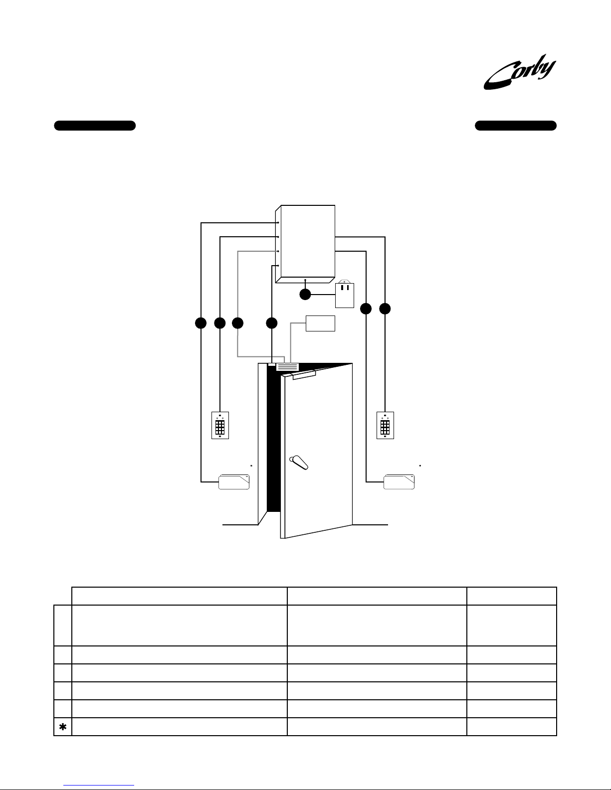
System 2 - Model 2016
One Door Control with Anti-Passback
Model 2016
access control
systems
A B C D
CONTACT
2 3
1
5 6
4
9
7 8
0
#
*
IN Keypad
and/or
IN Card Reader
Corby Card
PART NUMBERS AND WIRE SPECIFICATIONS
DESCRIPTION
Card Reader: Choose from Bar Code, Data Chip*, Magnetic Stripe, Proximity
and 30 bit Wiegand. All readers have the necessary LEDs for visual
A
feedback. Only one card technology can be used at a time.
Supports 26 and 30-bit Wiegand card formats.
Keypad: Choose from any one of seven indoor or outdoor keypads w/ LEDs.
B
Magnetic Door Lock or Door Strike
C
Magnetic Contact: Use for Door Ajar / Forced Entry.
D
A second contact can be used for zone monitoring.
Transformer: Supplied with the System 2. 16.5VAC 40VA
E
Data Chip readers require a different conductor wire.
E
40VA
16.5
VAC
A B
POWER
SUPPLY
MAG LOCK
2 3
1
5 6
4
9
7 8
0
#
*
OUT Keypad
and/or
OUT Card Reader
Corby Card
(Part Numbers) are for WireSignal
WIRE TYPE
5 conductor, 22 gauge, shielded - 500 feet maximum. (67005)
The wire length can be increased using an extender module.
8 conductor, 22 gauge, shielded - 1000 feet maximum. (67007)
2 conductor, 22 gauge, shielded - 1000 feet maximum. (95211)
2 conductor, 22 gauge, shielded - 1000 feet maximum. (95211)
2 conductor, 18 gauge, non-shileded. (93302)
5 conductor, 22 gauge, shielded - 100 feet maximum.
BOLD = Outdoor Version
PART #
Bar Code:
4150
Mag Stripe: 4073,
Wiegand: , ,
404240444046
Prox: ,
4173-41744175-4176
4010, , 4014, ,
40124062
4063, ,
40644066
4252 Magnetic Lock
4253 Door Strike
4255
SUPPLIED
4302-4307
4075
For further assistance, call (800) OK CORBY
Page 5
QUICKGUIDE TO ACCESS CONTROL INSTALLATION
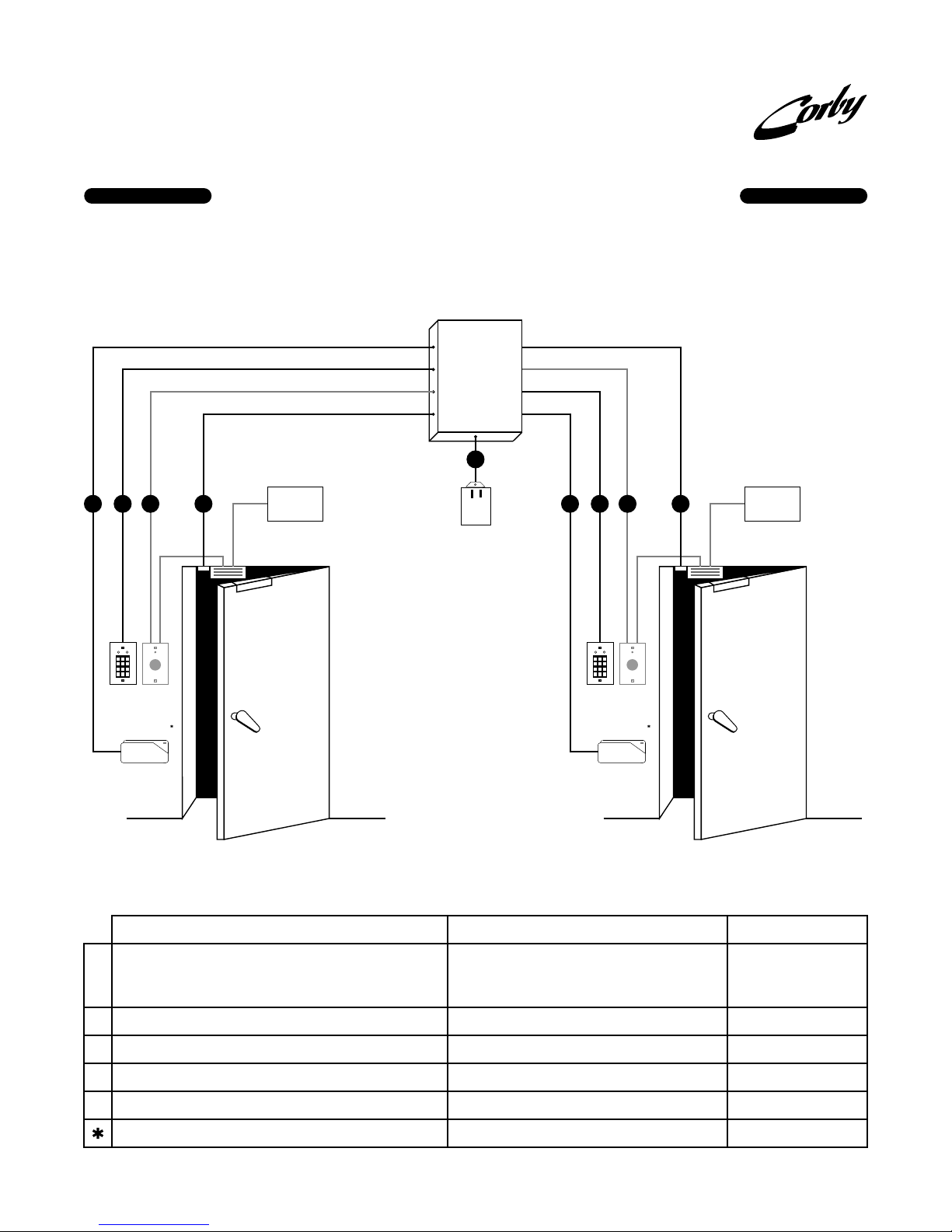
System 2 - Model 2016
Two Door Control
Model 2016
E
access control
systems
MAG LOCK
POWER
SUPPLY
A B C D
CONTACT
DOOR 1
PUSH TO EXIT
2 3
1
5 6
4
9
7 8
0
#
*
OUT RTE
IN Keypad
and/or
IN Card Reader
Corby Card
If using a door strike to secure the door, a Request-To-Exit button may not be necessary.
PART NUMBERS AND WIRE SPECIFICATIONS
DESCRIPTION
Card Reader: Choose from Bar Code, Data Chip*, Magnetic Stripe, Proximity
and 30 bit Wiegand. All readers have the necessary LEDs for visual
A
feedback. Only one card technology can be used at a time.
Supports 26 and 30-bit Wiegand card formats.
Keypad: Choose from any one of seven indoor or outdoor keypads w/ LEDs.
B
Request-To-Exit Button: Choose from a heavy-duty or light duty version.
C
The RTE Button would be located on the opposite side of the door (interior).
Magnetic Contact: Use for Door Ajar / Forced Entry.
D
A second contact can be used for zone monitoring.
Transformer: Supplied with the System 2. 16.5VAC 40VA
E
Data Chip readers require a different conductor wire.
40VA
16.5
VAC
(Part Numbers) are for WireSignal
A B C D
CONTACT
PUSH TO EXIT
2 3
1
5 6
4
9
7 8
0
#
*
OUT RTE
IN Keypad
and/or
IN Card Reader
Corby Card
WIRE TYPE
5 conductor, 22 gauge, shielded - 500 feet maximum. (67005)
The wire length can be increased using an extender module.
8 conductor, 22 gauge, shielded - 1000 feet maximum. (67007)
6 conductor, 22 gauge, shielded - 1000 feet maximum.
2 conductor, 22 gauge, shielded - 1000 feet maximum. (95211)
2 conductor, 18 gauge, non-shileded. (93302)
5 conductor, 22 gauge, shielded - 100 feet maximum.
POWER
SUPPLY
MAG LOCK
DOOR 2
BOLD = Outdoor Version
Bar Code:
Mag Stripe: 4073,
Wiegand: , ,
Prox: ,
4010, , 4014, ,
4063, ,
4035 Heavy-Duty
4135 Light- Duty
4255
SUPPLIED
4302-4307
PART #
4150
4075
404240444046
4173-41744175-4176
40124062
40644066
For further assistance, call (800) OK CORBY
Page 6
QUICKGUIDE TO ACCESS CONTROL INSTALLATION
System 2 - Model 2016
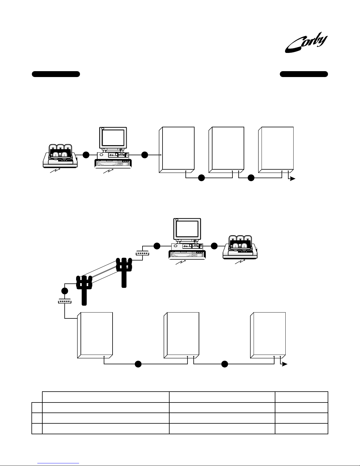
Communication with a PC
On-Site Communications
Model 2016 Model 2016 Model 2016
AC
access control
systems
OPTIONAL LOCAL PARALLEL
PRINTER (CENTRONICS STYLE)
CONNECT ONLY TO YOUR PC
YOUR PC WITH STANDARD TERMINAL
EMULATOR SOFTWARE. CAPABLE OF
VT-100 EMULATION.
Remote Communications
1200 - 9600
BAUD MODEM
A
1200 - 9600
BAUD MODEM
Model 2016 Model 2016Model 2016
A
YOUR PC WITH STANDARD TERMINAL
EMULATOR SOFTWARE. CAPABLE OF
VT-100 EMULATION.
B B
Maximum of 8 control panels (16 doors)
C
OPTIONAL LOCAL PARALLEL
PRINTER (CENTRONICS STYLE)
CONNECT ONLY TO YOUR PC
TO MORE 2016’
s
PART NUMBERS AND WIRE SPECIFICATIONS
DESCRIPTION
PC or Modem: PC runs using standard terminal emulation software.
A
RS485: Communications loop for multiple System 2’s. Eight total (16 doors).
B
Printer: Parallel (connects to PC). Serial (connects directly to panel).
C
For further assistance, call (800) OK CORBY
B B
Maximum of 8 control panels (16 doors)
(Part Numbers) are for WireSignal
WIRE TYPE
5 conductor, 22 gauge, shielded - 100 feet maximum. (67005)
2 conductor, 22 gauge, shielded, twisted pair.
4000 feet maximum from first unit to last unit. (93302)
Standard parallel printer cable.
TO MORE 2016’
PART #
4412 PC
4100 Video Display Terminal
4126
N/A
s
Page 7

QUICKGUIDE TO ACCESS CONTROL INSTALLATION
Equipment Checklist
access control
systems
SYSTEM 2 PANELS
2003Supports 1 Door, 280 Users with names - 485 without
2016Same as 2003 but adds: Second Door, Anti-Passback,
2020Upgrade Kit for P/N 2003: Adds Second Door,
OPTIONAL PROGRAMMING DEVICE
4100Video Display Terminal
KEYPADS
Indoor
4010Single-gang, flush mount with one green LED
4014Hidden View with tamper switch, One Green and Red
4063Heavy-Duty, flush mount w/ on e Green & Red LED
names maximum, 256 Time/Holiday Cells, Full Duplex
RS232,
Generic 26-bit Wiegand Card Capability,
Auxiliary Relay #1 and Voltage Output #1, Forced
Entry, & Door Ajar Inputs, Emergency Drop Input,
Request-To-Exit Input, and One Zone Input. Includes
heavy-duty steel Cabinet, 48 Character LCD,
16.5 VAC Transformer, 12 V 4AH stand-by battery,
Installation manual
Temporary Users, One Zone Input, Auxiliary Relay #2,
One Voltage Output, Large RAM, RS485, eight (8)
additional Time Schedules and code and schedule
linkage to auxiliary outputs.
^
Large RAM supports additional users.
Anti-Passback, Temporary Users, One Zone Input,
Auxiliary Relay #2, One Voltage Output, Large RAM,
RS485, eight (8) additional Time Schedules and code
and schedule linkage to auxiliary outputs.
LED, Single-gang, surface mount
^
Wiegand Readers
4042Indoor/Outdoor swipe (beige)
4044Indoor/Outdoor swipe (black)
4046Indoor/Outdoor Insertion reader (black)
Wiegand Cards
4047Plain white, Photo ID
4048Corby logo Photo ID
4049Standard 30 bit card
HID Proximity Readers
4173Indoor/Outdoor, 10" - 27" read range
4174Indoor/Outdoor, 1" - 9" read range
4175Indoor/Outdoor, thinline 2" - 4" read range
4176Indoor/Outdoor, mullion 2" - 5" read range
HID Proximity Cards
4170Keyfob, 26 bit
4171Credit card size w/ badge slot, 26 bit
4172Credit card size, graphics quality for photo ID, 26 bit
Magnetic Stripe Readers
4073Indoor, surface mount, swipe (black)
4075Indoor/Outdoor, surface mount, swipe, (beige)
Magnetic Stripe Cards
4074Credit card size, for use with 4073, 4075 readers
Bar Code Readers
4150Indoor/Outdoor, surface mount, swipe, (black)
(4052 mounting b racket recommended)
(4060 mounting hardware kit recommended)
Outdoor
4012Aluminum cover, surface mount w/ one Green & Red
LED. Also includes 12VDC night light
4062Cast metal Heavy-Duty mounted in a Lock-box and on
a goose neck. Includes one Green and Red LED
4064Cast metal Heavy-Duty mounted in a Lock-box.
Includes one Green and Red LED
4066Cast metal, flush mount, Heavy-Duty with one Green
and Red LED
READERS
Data Chip Readers
4302Single-gang, flush mount, with one Green LED
4303Single-gang, flush mount, with one Green & Red LED
4304Narrow, flush mount with one Green LED
430 5Narrow, flush mount with one Green and Red LED
4306Reader Head and one Green LED
4307Narrow, (black) surface mount with bi-color LED,
back-lit read head and mounting hardware
Data Chips
4320Chip assembled on a key-ring with Corby logo
4321Chip Only - For use with badges, photo ID cards etc.
4323Roll of double stick tape (dots) for adhering Data Chip -
100 pieces per roll (required for 4321)
For further assistance, call (800) OK CORBY
Bar Code Cards
4151Credit card size
MODEMS
4118Short haul up to 1 mile.
4126Phone modem. Connect One at the circuit board
location and one to the VDT or PC
12 VDC DOOR LOCKS (Require 4094 Power Supply)
4252Magnetic Lock for doors that swing out.
4253Door strike for metal or wood door frames
EXIT DEVICES
4035Heavy-duty exit button (LED illuminated)
4135Light-duty exit button
POWER SUPPLIES
40946-12 Volt with 6A lead acid battery and transformer
MISCELLANEOUS
2018Data Chip Programming Wand for faster and easier
programming of Data Chips
4056Line Extender Module. Increases distance 500 feet.
4255Magnetic Door Contact
Page 8
QUICKGUIDE TO ACCESS CONTROL INSTALLATION
access control
systems
Architectural Specifications
System 2 - Model 2003
The access control system will be a Corby Model 2003 “System 2" or approved equal. System will control one door. System will be housed
in a metal cabinet measuring 15.5" x 11" x 4.5". Cabinet will have a hinged door with a lock to prevent unauthorized access to the wiring.
Memory allocation for users, event storage and mode of operation will be user adjustable. System will support 527 maximum users and be
programmable from a built-in keypad and 48 character LCD display. System will provide an RS-232 interface for optional programming
through a video display terminal, PC or the connection of a printer.
System will provide built-in charging for an external lead acid battery to support full system operation upon loss of main AC power. Each twodoor unit will contain a lithium battery for backup of user, system and event data upon loss of main AC power and main battery backup.
System supports a perpetual clock and calendar system, accurate to the year 2086.
Eight time schedules will be provided for the control of users, doors and auxiliary functions. Each time schedule will consist of 32 cells each
for a total of 256 time cells. Auxiliary relay outputs will be triggerable from twenty different system events.
System will contain two direct inputs for each of the following: Keypad, Wiegand (including swipe, insert and Proximity), Bar code, Magnetic
Stripe and Touch Memory readers, Door Ajar/Forced Entry, Request-To-Exit and Zone. An input will be provided for an emergency dr op of
the main door relays. The system will accept BCD encoded keypad codes, a proprietary Corby 30 bit Wiegand code, generic 26
Code-39 bar code, track-two magstripe code and Dallas Touch Memory device codes. System will provide 5 VDC @ 125ma. And 12
code,
VDC @ 250ma. for card readers. Resettable fuses will provide protection for five and 12 volt outputs, AC power and rechargeable battery.
System will contain two of the following outputs: Door relay consisting of form A and form C contacts rated 5 a mps @ 30 VDC, Red and
Green LED indicator. The following additional outputs will be provided for signaling, shunt and schedule control: Two form C relays rated five
amps, 30VDC, and two voltage outputs rated -50 mA.
bit Wiegand
SYSTEM 2 - Model 2016
The access control system will be a Corby Model 2016 “System 2" or approved equal. System will control two doors. System will be
housed in a metal cabinet measuring 15.5" x 11" x 4.5". Cabinet will have a hinged door with a lock to prevent unauthorized access to the
wiring. Mem ory allocation for users, event storage and mode of operation will be adjustable. System will be programmable from a built-in
keypad and 48 character LCD display. System will provide an RS-232 interface for optional programming through a video display terminal,
PC or the connection of a printer. System will provide an RS-485, two wire interface for connection to other System 2's in a network. A
maximum of eight systems will be networkable to provide control for 16 doors.
System will provide b uilt-in charging for a lead acid battery to support full system operation upon loss of main AC power. System will contain
a lithium battery for backup of user, system and event data upon loss of main AC power and main battery backup. System will support a
perpetual clock and calendar system, accurate to the year 2086.
System will support 6000 users in two door, standalone mode and 4000 users in network mode. 16 time schedules will be provided for the
control of users, doors and auxiliary func tions. Each time schedule will consist of 64 cells each for a total of 1024 time cells. System will
allow hard and soft antipassback. Auxiliary relay outputs will be triggerable from twenty different system events.
System will contain two direct wire inputs for each of the following: Keypad, Wiegand (including swipe, insert and Proximity), Bar code,
Magnetic Stripe and Touch Memory readers, Door Ajar/Forced Entry, Request-To-Exit and Zone. An input will be provided for an emergency
drop of t he main door relays. The system will accept BCD encoded keypad codes, 26 bit standard Wiegand codes, a proprietary Corby 30
bit Wiegand code, 26a Code-39 bar codes, track-two magstripe codes and Dallas Touch Memory device codes. System
will provide 5 VDC @ 125 ma. and 12 VDC @ 250 ma. for card readers. Resettable fuses will provide protection for 5 and 12 volt outputs, AC
power and rechargeable battery.
bit Wiegand code,
access control
systems
Corby Industries, Inc.
1501 E. Pennsylvania Street
Allentown, PA 18103
Phone: (610) 433-1412 Toll Free: (800) 652-6729
Fax: (610) 435-1963 http://www.corby.com
P/N F9921 June 18, 1998 k:\corel\instruct\quickgde.cdr
 Loading...