

Page 1
TROUSER PRESS
USER GUIDE
GUIDE DE L’UTILISATEUR
BENUTZERANLEITUNG
GUIA DEL USUARIO
GUIDA PER L’UTENTE
GEBRUIKSAANWŸZING
GEBRUIKSAANWIJZING
BRUGERVEJLEDNING
BRUKSANVISNING
BRUKSANVISNING
KÄYTTÖOPAS
УКООДСО О
КСЛУ
Page 2
CORBY
3300
CORBY
4400
CORBY
7700
CORBY
CLASSIC/DELUXE
CORBY
STATESMAN
12
13
1
2
3
4 5
6
7
8
9
10
11
Page 3

IMPORTANT SAFETY
INSTRUCTIONS
When using your appliance, basic precautions should always be
followed, including the following:
1. Read all the instructions.
2. Use the appliance only for its intended purpose.
3. To reduce the risk of electric shock, do not use appliance in a
bathroom, do not immerse the appliance in water or other liquids.
4. Never yank cord to disconnect from outlet: instead, grasp plug and
pull to disconnect.
5. Do not operate appliance with a damaged cord or if the appliance
has been dropped or damaged. Special purpose tools are required
to replace the cord. To reduce the risk of electric shock, do not
disassemble or attempt to repair the appliance. Take it to a
qualified service person for examination or repair. Incorrect
reassembly or repair could cause a risk of fire, electric shock, or
injury to persons when the appliance is used.
6. Close supervision is necessary for any appliance being used by or
near children, the elderly or infirm persons. Do not leave appliance
unattended while connected.
Item 7 applies to the U.S.A. and Canada only.
7. To reduce the risk of electric shock, this appliance has a polarised
plug (one blade is wider than the other). This plug will fit in a
polarised outlet only one way. If the plug does not fit fully in the
outlet, reverse the plug. If it still does not fit, contact a qualified
electrician to install the proper outlet.
Do not change the plug in any way.
8. If the appliance is fixed (wallmounted), it must be positioned so the
plug is accessible.
SAVE THESE INSTRUCTIONS
Corby have specialised in making trouser presses since the 1930s when the
company was founded in Windsor, England. Today Corby sell presses for
home and hotel use throughout the world. Although there have been many
technical changes since that time we have continued with the tradition of
producing high quality British products. Each press is hand assembled and
individually tested prior to despatch from our Andover factory.
Assembly Instructions
Please check the contents carefully and contact your supplier if any of the contents
are missing or damaged. For the safety of babies and young children please
dispose of all plastic bags.
Feet
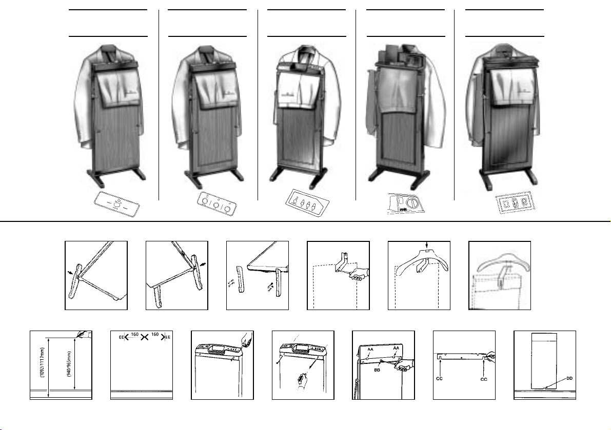
CORBY 3300/4400/7700/CLASSIC (Diagrams 1 & 2)
For stability ensure that the LONGEST part of the foot is at the FRONT of the
press. Tilt the press to one side and slide the foot onto moulding. A sharp tap with
the hand will click the foot into place. Turn the press over and repeat the
procedure for the other foot. Stand the press upright.
CORBY CLASSIC DELUXE/STATESMAN
(Diagram 3)
Contents: 4 Bolts and 4 Washers
For stability ensure that the LONGEST part of the foot is at the FRONT of the
press. Lay the press on its side and using the bolts provided, bolt the foot to the
bottom of the press, making sure that the washer is between the head of the bolt
and the foot. Turn the press over and repeat the procedure for the other foot.
Stand the press upright.
Hanger
CORBY 3300/4400 (Diagrams 4 & 5)
Contents: 2 x Hanger Screws
Screw hanger bracket to back of the press matching the LOWEST hole in the
bracket to the LOWER hole in the back of the press. Insert the second screw into
the TOP hole. With the hole facing the rear, slide the hanger onto the bracket until
it clicks home.
Assembly Instructions
Page 4

CORBY 7700 (Diagrams 4 & 5)
Contents: 2 x Hanger Screws
Rest the hanger bracket on the small ledge provided at the rear of the top section
of the press. This will align two of the holes in the bracket with two holes in the
top section. Use the two screws provided to affix the hanger to the top section.
With the hole facing the rear, slide the hanger onto the bracket until it clicks
home.
CORBY CLASSIC (Diagrams 4 & 5)
Note: The fixing screws are supplied in position in the back of the press.
Remove the fixing screws to fit the hanger. Screw hanger bracket to back of the
press, matching the LOWEST hole in the bracket to the LOWER hole in the back
of the press. Insert the second screw in the MIDDLE hole. With the hole facing the
rear, slide the hanger onto the bracket until it clicks home.
CORBY CLASSIC DELUXE/STATESMAN
(Diagram 6)
Contents: 2 flange head screws
Note: The fixing screws are supplied in position in the back of the press.
Attach the hanger to the hanger bracket by passing the two flange head screws
through the bracket, from the underside, into the two pre-drilled holes in the
hanger and tighten. Loosen the two screws in the back of the press, but do NOT
unscrew completely. Slot the hanger bracket over the screws and tighten.
Wall-mounting
WARNING: Make sure the wall is suitable and that there are no hidden electricity,
water or gas supply pipes or any other hidden services, if in doubt seek qualified
advice.
CORBY 3300/4400
(Diagrams 7, 8 &13)
Contents: 2 x large wall plugs, 2 large screws, 1 small wall plug,
1 small screw, 1 star washer.
NOTE: Screws supplied are suitable for most types of solid walls.
Measure a point 940mm above the skirting board or a minimum of 1092mm
above the floor and lightly mark with a horizontal line (Diagram 7). Mark the
vertical centre position of the press on the horizontal line. Mark points 160mm
either side of the vertical centre position to indicate hole positions (EE) (Diagram
8). Drill holes to suit large wall plugs provided. Insert the two large wall plugs
into the holes and fit screws. Tighten screws until only 6mm of screw is left
protruding. Hang the press on the screws. Mark the position of retaining screw
(DD) (Diagram 13). Lift press from the wall and drill hole suitable for the small
wall plug at the position marked. Fit the small wall plug into hole. Hang the press
back on the wall and fit small screw into the washer and into small wall plug and
tighten. Ensure washer is not trapped between press and the wall.
It is essential that you do not omit the final stage (DD) (Diagram 13). Failure to do
so can result in damage to the head section of the press and may invalidate the
guarantee.
CORBY 7700
(Diagrams 7, 9, 10 & 13)
Contents: 2 x large wall plugs, 2 long screws, 1 small wall plug,
1 small screw, 1 star washer.
NOTE: Screws supplied are suitable for most types of solid walls.
Push out the wall-mounting tube caps using a screwdriver inserted into the tubes
from the rear (Diagram 9). Mark wall in two positions horizontally 250mm apart
and at least 940mm above the skirting board (Diagram 7). Drill holes at positions
marked suitable for the wall plugs to be used (if using supplied parts these will be
the brown wall plugs). Fit wall plugs into holes in wall. Push screws, to be used (if
using supplied parts these will be the long screws), through wall-mounting tubes
from the front (Diagram 10). Lift the press and align screws with wall plugs. Lightly
insert screws into wall plugs; do not fully tighten. Mark position for lower retaining
screw (if using supplied parts this will be the small screw), (DD) (Diagram 13).
Undo top screws and remove press from wall. Drill a hole at position marked
suitable for small wall plug. Insert small wall plug into hole. Fit the press back onto
the wall and fully tighten the top two screws. Fit the washer provided over the
small screw and insert into the small yellow wall plug; fully tighten ensuring that
the rear of the press is between the washer and the wall.
It is essential that you do not omit the final stage (DD) (Diagram 13). Failure to do
so can result in damage to the head section of the press and may invalidate the
guarantee.
CORBY CLASSIC
Retail Models
(UK only)
A wall-mounting kit is available and can be ordered direct from Corby.
Hotel Models (Diagrams 7, 11, 12 & 13)
Contents: A wall-mounting kit comprises of 1 bracket, 2 large screws and wall plugs, 1 small
screw and wall plug and washer.
NOTE: Screws supplied are suitable for most types of solid walls.
Assembly Instructions
Page 5

If you specifically ordered a wall-mounted model, the bracket will be in position
on the back of the press.
Loosen two screws (AA) leaving 6mm of the head protruding (Diagram 11).
Remove screw (BB) which releases the wall-mounting bracket.
Do not discard the screw. Measure a point 965mm above the skirting board or a
minimum of 1117mm above the floor and lightly mark a horizontal line at least
356mm long (Diagram 7). Place top edge of bracket along the horizontal line
and mark the wall at the top of the two slots (CC) (Diagram 12).
Drill holes to depth of 50mm at positions marked, using an 8mm masonry drill.
Insert the two large wall plugs and screw in the large screws, leaving 6mm of the
heads protruding.
Refit the bracket to the press, making sure NOT to overtighten the screws. Hang
the press onto the screws in the wall. Mark position for retaining screw (DD) on
the wall, then lift press off the wall (Diagram 13). Drill a hole 40mm deep at the
position marked. Insert the small wall plug, fit the washer over the small screw and
screw it into the wall leaving 10mm protruding.
Fit the press back on the wall, ensuring that the slots line up with all
3 screws. Make sure that the washer is NOT trapped between the press and the
wall, then tighten the retaining screw.
It is essential that you do not omit the final stage (DD) (Diagram 13). Failure to do
so can result in damage to the head section of the press and may invalidate the
guarantee.
Electrical Connections
This is a double insulated product manufactured to internationally recognised safety
standards (as designated by IEC-335-1).
The supply cord of this appliance cannot be replaced, because special purpose
tools are required. If the cord is damaged, the appliance MUST be returned to
either the retailer, from whom you made your purchase, or the in-country
distributor. If you have a problem in locating either, or you need advice of any
kind, do please make contact direct with the manufacturer, John Corby Limited
(England). We will be happy to help.
Double insulated products should in no circumstances be connected to earth as
this could adversely affect the safety of the product.
In keeping with other manufacturer’s of domestic appliances, we recommend that
when not in use the product should be switched off at the mains supply socket and
the plug disconnected.
Europe
IMPORTANT If you replace the plug it must be wired in accordance with the
relevant colour code given below:
This product must be fitted with two core mains lead connected:
BROWN - LIVE (L)
BLUE - NEUTRAL (N)
UK, Republic of Ireland, Isle of Man and Channel Isles
PLUGS. Your press should be fitted with a 3-pin BS 1363A 13 amp plug fitted
with a 3 amp BS 1362 ASTA approved fuse. If any other plug or connection type
is used then there must be a 5 amp fuse in the plug adaptor or distribution board.
Fitting a fuse of higher rating may invalidate your guarantee. If you remove the
plug from the mains lead, please destro
y as exposed wires will become live if the
plug is inserted into a mains socket.
General Operation
Just raise the lever arms and your Corby press will open wide to reveal the
heating pad. This pad is cushioned to accept different fabric thickness and raised
seams. At the base of the pad there is a 75mm deep section which adjusts
automatically to accommodate the extra thickness of turn-ups and hems; this
ensures an even pressure over the whole area of the trousers.
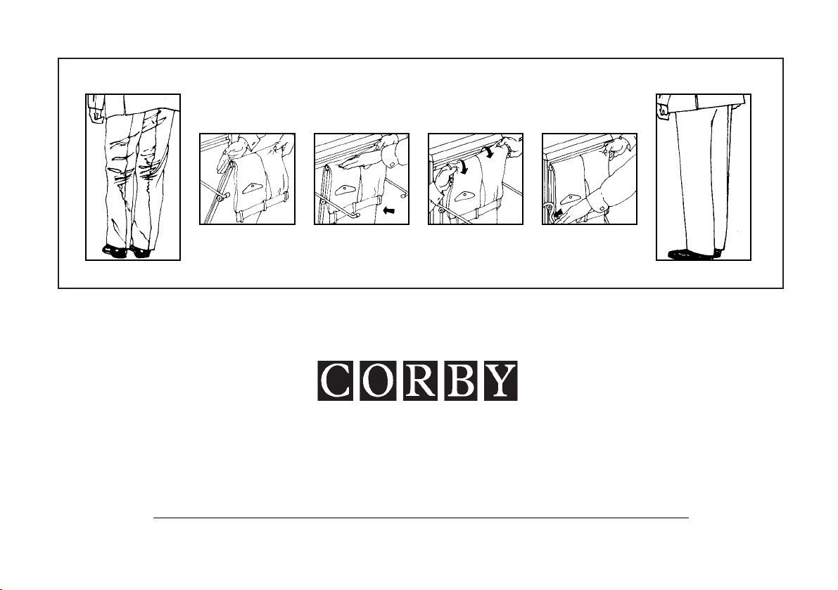
Insert your trousers “feet” first into the base of the press. Smooth them into position,
ensuring the existing creases are in line. As you close the press your trousers will be
gently held at the feet. Firmly grip the top of your trousers, gently pulling while you
close the press. Push down on one of the lever arms to lock into position. (See
illustration on back cover).
If you look to the top of the frontboard, you will see one of the pair of ribbed
stretcher bars, which meet and lock into an upright position just as you finally
close the press. The action of these stretcher bars gently grips and pulls trousers
back into shape, removing those back-of-knee wrinkles which can spoil the
English
Assembly Instructions / Electrical Connections / General Operation
Page 6

appearance of your trousers. These stretcher bars are essential to the design of a
good trouser press and are unique to Corby.
You can safely leave your trousers in the press until they are next required or until
you wish to use the press again. The material will retain the creases for longer if
you allow the trousers to cool before wearing.
Tips and Hints
Using your Corby press daily will add to the life and appearance of your trousers.
Your Corby is safe to use on any material which you would normally iron,
however, you should check for any special instructions before pressing. One of the
benefits of your Corby is that it will not impart a surface shine on the material,
something which can occur after repeated ironing. The inherent humidity content
of natural and mixed fibres assists the pressing process, however, some man-made
fibres, such as polyester, resist humidity and may therefore require extra pressing.
On no account should any trousers be dampened before pressing.
Please press one pair of trousers at a time, ensuring that all pockets are emptied
of keys, coins or other sharp objects as they could damage the heating pad.
If the heating pad in your trouser press is damaged or shows signs of excessive
wear, then the press should be returned for examination.
The inside of the frontboard may be wiped with a dry cloth, but no polish or
cleaner should be used on the inner frontboard or heating pad surface.
You will extend the life of the heating pad if you take care not to leave the press
switched on with the frontboard open.
User Instructions
PLEASE ALLOW A FEW SECONDS DELAY BETWEEN SWITCHING ON AT THE
WALL AND USING THE PRODUCT.
CORBY 3300
Start the timer by pushing the ON/(CANCEL) button, the indicator light will glow
while in operation and will go out to indicate that the press has automatically
switched off. The pressing cycle can be cancelled at any time by a second push of
the (ON)/CANCEL button.
CORBY 4400
Select the required time by pushing the 15 or 30 minute buttons. The time select
indicator light will glow. Start the timer by pushing the ON/(CANCEL) button, the
indicator light will glow while in operation and will go out to indicate that the
press has automatically switched off. The pressing cycle can be cancelled at any
time by a second push of the (ON)/CANCEL button. Please note should you
decide to cancel the operation the indicator light for the (ON)/CANCEL will go
out immediately, but the time selected will remain lit for approx 5 minutes, giving
you an opportunity to restart the pressing cycle should you so desire.
CORBY 7700
On start-up a steady zero will be displayed. Select the required time by pushing
either the 15, 30 or 45 minute button. The display will confirm the time selected.
Time selection may be changed at this stage if desired. Start the timer by pushing
the ON button. The indicator light will glow while in operation and the display
will indicate the time remaining in minutes. The pressing cycle can be cancelled at
any time by a second push of the ON button, the display will return to zero.
CORBY CLASSIC/DELUXE
Start the timer by turning the dial clockwise to the required time position 15, 30
or 45 minutes. The indicator light will glow while in operation and will go out to
indicate that the press has automatically switched off. During the pressing
operation the timer will slowly return to zero. The pressing cycle can be cancelled
at any time by turning the dial anti-clockwise to zero.
CORBY STATESMAN
Open the top hinged section and select the required time pressing the 15/30
minute switch. Start the timer by pushing the O/1 (Standby/On) button, the
indicator light will glow while in operation and will go out to indicate that the
press has automatically switched off.
The pressing cycle can be cancelled at any time by a second push of the O/1
(Standby/On) button.
Your CORBY STATESMAN trouser press is made from a mixture of solid wood and
real wood veneer.
Wood is a natural product and as such there is a variety in the grain and depth of
colour throughout the material. This is reflected in the construction of the
STATESMAN and we believe this adds to its attraction.
In acknowledging the need to wisely use the Earth’s resources we only use timber
which has originated from known controlled sources.
General Operation / User Instructions
Page 7
EnglishGuarantee
GUARANTEE
(All countries excluding UK, Republic of Ireland,
Isle of Man and Channel Isles.)
Each Corby trouser press carries a unique serial number which
is located on the outside of the carton and repeated on the
label affixed to the base of the press, between the feet. A
typical number is as follows: 98001234. Please make a note of
this, it may be helpful for you to quote the number, should a
problem ever occur with your Corby.
Serial No.
Date of Purchase
The period and terms of the guarantee will depend on your
local regulations. If a problem occurs you should initially
contact either the retailer, from whom you made your purchase
or the in-country distributor. If you have a problem in locating
either, or you need advice of any kind do please make contact
with John Corby Limited in England. We will be happy to help.
REST OF THE WORLD
For any enquires please call: +44 1264 325105. Fax: +44 1264 332832. E-mail: [email protected]
Page 8
JOHN CORBY LIMITED
NORTH WAY, WALWORTH ESTATE, ANDOVER, HAMPSHIRE, SP10 5LX, ENGLAND.
TEL: +44 (0) 1264 355577. FAX: +44 (0) 1264 332832.
Web: www.corbypress.com
E-mail: [email protected]
PA RT: A54540 - T.P./11.02
Certain models not available in every country. Technical specifications may vary between countries. Dimensions quoted are all approximate. Errors and omissions
excepted. John Corby Limited reserve the right to alter the specifications of any model to meet worldwide marketing requirements.
 Loading...