

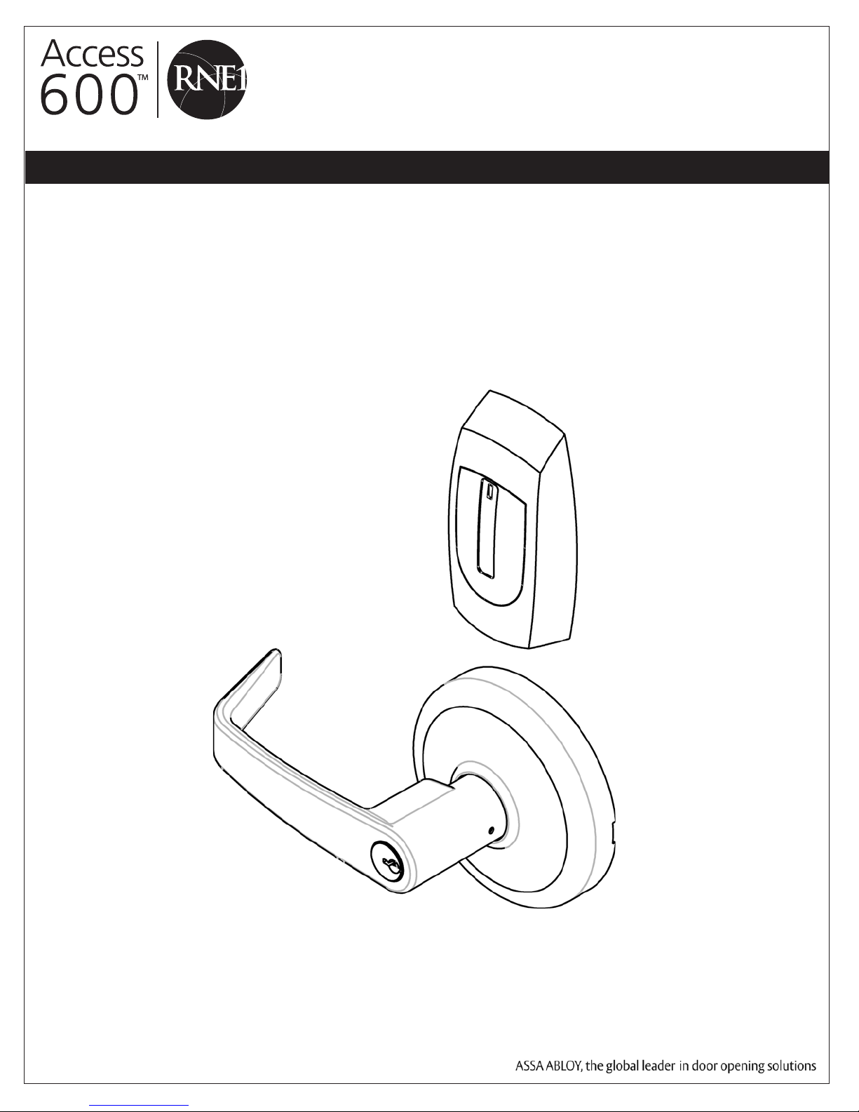
Corbin Russwin CL33600 Installation Instructions Manual
Cylindrical Lockset Installation Instructions
CL33600 TCRNE1 Series
M812 - iCLASS® Reader Option
FM313 6/09 (617417060)
Attention Installer
Please read these instructions carefully to prevent missing important steps.
Please Note: Improper installations may result in damage to the lock and void the factory warranty.
Important: The accuracy of the door preparation is critical for proper functioning and security of this lock.
Misalignment can cause premature wear and a lessening of security.
For Technical Assistance call Corbin Russwin at 1-800-810-WIRE (9473)
Copyright © 2009 Corbin Russwin, Inc., an ASSA ABLOY Group company.
All rights reserved. Reproduction in whole or in part without the
express written permission of Corbin Russwin, Inc. is prohibited.
CL33600 Series Cylindrical Lock
1) Warning ................................................................................2
Table of Contents
2) General Description
3) Specifications / Features
4) Product Illustration
5) Installation Instructions
6) Wiring Diagrams
7) Mechanical Operational Check
8) Electrical Operational Check
.............................................................3
....................................................3
.............................................................4
......................................................5
................................................................12
.........................................16
.............................................16
1) Warning
Warning: Changes or modications to this unit not expressly approved by the party
responsible for compliance could void the user’s authority to operate the equipment.
This device complies with Part 15 of the FCC Rules. Operation is subject to the following two conditions: (1) this device
may not cause harmful interference, and (2) this device must accept any interference received, including interference that
may cause undesired operation.
Note: This equipment has been tested and found to comply with the limits for a Class B digital device, pursuant to Part
15 of the FCC Rules. These limits are designed to provide reasonable protection against harmful interference in a residential installation.
This equipment generates, uses and can radiate radio frequency energy and if not installed and used in accordance with
the instructions, may cause harmful interference to radio communications. However, there is no guarantee that the interference will not occur in a particular installation. If this equipment does cause harmful interference to radio or television
reception, which can be determined by turning the equipment off and on, the user is encouraged to try to correct the
interference by one or more of the following measures:
• Reorient or relocate the receiving antenna
• Increase the separation between the equipment and receiver
• Connect the equipment into an outlet on a circuit different from that to which the receiver is connected
• Consult the dealer or an experienced technician for help
The term “IC:” before the radio certification number only signifies that Industry Canada technical specifications were
met. This Class B digital apparatus meets all requirements of the Canadian Interference Causing Equipment Regulations.
Operation is subject to the following two conditions: (1) this device may not cause harmful interference, and (2)
this device must accept any interference received, including interference that may cause undesired operation.
Cet appareillage numérique de la classe B répond à toutes les exigences de l’interférence canadienne causant des
règlements d’équipement. L’opération est sujette aux deux conditions suivantes: (1) ce dispositif peut ne pas causer
!
l’interférence nocive, et (2) ce dispositif doit accepter n’importe quelle interférence reçue, y compris l’interférence qui
peut causer l’opération peu désirée.
Observe precautions for handling electrostatic sensitive devices.
Copyright © 2009 Corbin Russwin, Inc. All rights reserved.
2
Reproduction in whole or in part without the express written
permission of Corbin Russwin, Inc. is prohibited.
CL33600 Series Cylindrical Lock
2) General Description
The Corbin Russwin Access 600 TCRNE1 Series cylindrical lock is designed to interface with existing Wiegand
Electrical Access Control (EAC) panels. The reader requires 12 or 24VDC for power and is compatible with HID
iCLASS 13.56 technology. The Access 600 technology is designed around Corbin Russwin’s Grade 1 hardware.
The cylindrical lock (with external DPS, Door Position Switch) comes with complete inside REX (request to exit)
monitoring and is available in 12VDC or 24VDC. Weatherseal gaskets are also included for outdoor applications.
The Access 600 reader provides visual (LED) and audible indication of lock state (locked/unlocked).
3) Specifications / Features
Latch – Stainless steel, ½” (13mm) throw
Optional: ¾” (19mm) throw deadlocking
fire latch for pairs of doors
• Deadlocking latch prevents manipulation when door closed
• Door Thickness – 1-3/4” (44mm) to 2” (50mm) standard
Optional 2” (50mm) to 2-1/4” (57mm) optional
• Outside lever controlled by reader or key retracts latch
• Inside Lever produces REX (request to exit) signal
• Fail Safe or Fail Secure operation (must specify)
• UL re listed
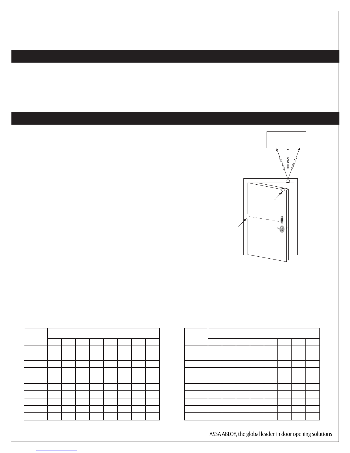
• Wire from EAC Panel to door must be shielded with a drain.
Drain terminated at EAC Panel controller
• Complete monitoring of door (External DPS supplied)
• Wires directly to EAC Panels
• Accepts all HID standard iCLASS bit formats
• QC12 Hinge with ElectroLynx plug and play
12VDC System
• Reader Draw = 125mA (maximum)
24VDC System
• Reader Draw = 125mA (maximum)
Wiegand Access
Control System
Door
Status
Switch
McKinney
Electronic
Transfer
Hinge
Patent Pending
• 12VDC Solenoid Draw =250mA (normal state)
• Total System Draw = 375mA
Wire Gauge Charts
Total
One-Way
Length of
Wire Run (ft)
Copyright © 2009 Corbin Russwin, Inc., an ASSA ABLOY Group company.
All rights reserved. Reproduction in whole or in part without the
express written permission of Corbin Russwin, Inc. is prohibited.
1/4A 1/2A 3/4A 1A 1-1/4A 1-1/2A 2A 3A
100 20 18 16 14 14 12 12 10
150 18 16 14 12 12 12 10 —
200 16 14 12 12 10 10 — —
250 16 14 12 10 10 10 — —
300 16 12 12 10 10 — — —
400 14 12 10 — — — — —
500 14 10 10 — — — — —
750 12 10 — — — — — —
1,000 10 — — — — — — —
1,500 10 — — — — — — —
Load Current @ 12VDC
• 24VDC Solenoid Draw = 150mA (normal state)
• Total System Draw = 275mA
Total
One-Way
Length of
Wire Run (ft)
3
1/4A 1/2A 3/4A 1A 1-1/4A 1-1/2A 2A 3A
100 24 20 18 18 16 16 14 12
150 22 18 16 16 14 14 12 10
200 20 18 16 14 14 12 12 10
250 18 16 14 14 12 12 12 10
300 18 16 14 12 12 12 10 —
400 18 14 12 12 10 10 — —
500 16 14 12 10 10 — — —
750 14 12 10 10 — — — —
1,000 14 10 10 — — — — —
1,500 12 10 — — — — — —
Load Current @ 24VDC
CL33600 Series Cylindrical Lock
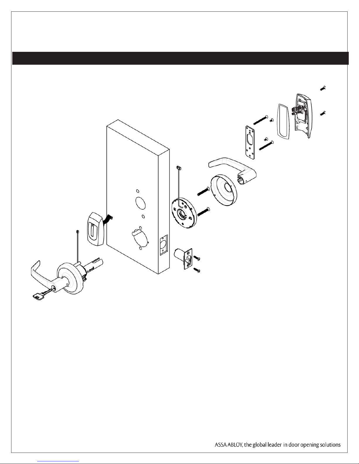
4) Product Illustration
Tools Required:
• Phillips Screw Driver (Standard size)
• Flat Blade Screw Driver (Standard size)
• 1/8" Allen Wrench
Copyright © 2009 Corbin Russwin, Inc., an ASSA ABLOY Group company.
All rights reserved. Reproduction in whole or in part without the
express written permission of Corbin Russwin, Inc. is prohibited.
4
CL33600 Series Cylindrical Lock
5) Installation Instructions
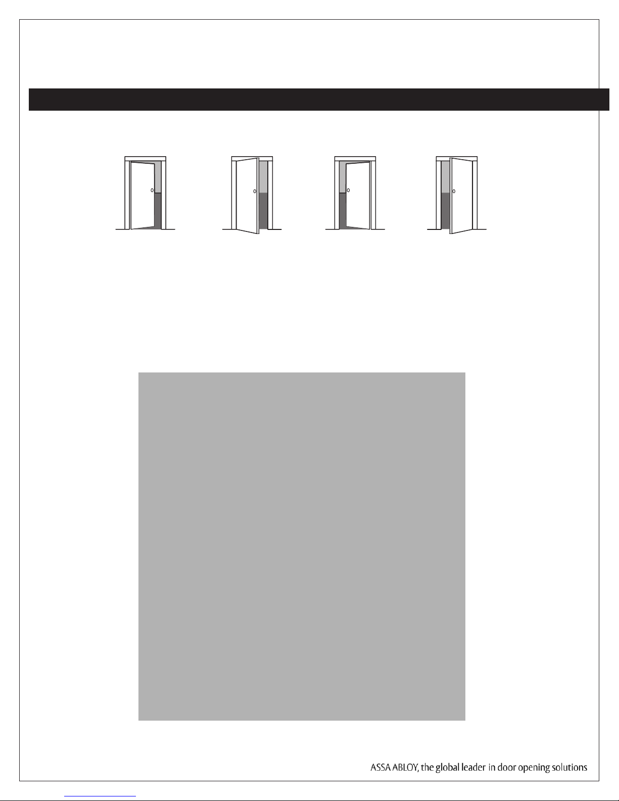
1. Verify Hand and Bevel of door. Illustrations shown are as viewed from the outside or secure
side of opening.
Left Hand
Hinges Left.
Open Inward.
“LH”
Left Hand
Reverse Bevel
Hinges Left.
Open Outward
“LHRB”
Right Hand
Hinges Right.
Open Inward.
“RH”
Right Hand
Reverse Bevel
Hinges Right.
Open Outward
“RHRB”
2. Prep door according to supplied door marker (FM291)). For door manufacture templates
visit www.corbinrusswin.com and reference template # T31071.
Outside Face of Door Outside Face of Door
Copyright © 2009 Corbin Russwin, Inc., an ASSA ABLOY Group company.
All rights reserved. Reproduction in whole or in part without the
express written permission of Corbin Russwin, Inc. is prohibited.
5
 Loading...