

Corbin Russwin Access 800, ML20800 TCAC2 Series Installation Instructions Manual
TM
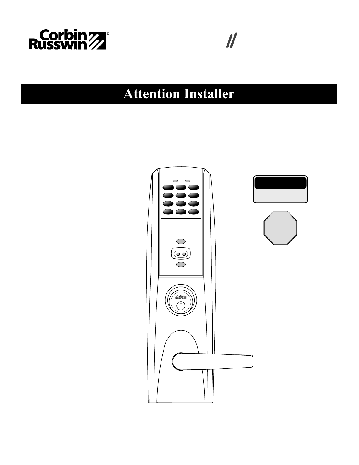
Access 800
Installation Instructions
For ML20800 TCAC2 Series
Mortise Lockset
Please read these instructions carefully to prevent missing important steps.
Please Note: Improper installation may result in damage to the lock and void the factory warranty.
Important: The accuracy of the door preparation is critical for proper functioning and security of this lock.
Misalignment can cause premature wear and a lessening of security.
FM 224A 3/07
(617417420)
1 2 3
475
8
0
*
CAUTION
6
9
#
DOOR MUST REMAIN OPEN
DURING INSTALLATION.
USE DOOR STOP.
TEST
FOR PROPER
OPERATION
BEFORE
CLOSING
DOOR
For installation assistance contact Corbin Russwin Inc., at 1-800-810-WIRE (9473)
Table of Contents
Page
1) Warning 1
2) General Description/Specifications/Features 2
3) ML20800 TCAC2 Series Product Illustration 3
4) Installation Instructions 4-10
5) Installation of RF Technology Lock 11
6) Operational Check 12
7) ML20800 TCAC2 Hard Wiring Instructions for Mortise 13
7.1) Important 13
7.2) Installation Notes 13
7.3) Electrolynx™ Connector System 13
7.4) ML20800 TCAC2 Series Illustration with M861 Harness 14
7.5) M861 Forced Door Propped Door Option 15
7.6) M35 Power/Remote Unlocking 16
7.7) M35 Power/Remote Unlocking with M861 Forced
Door Propped Door Option
17
1) Warning
Changes or modifications to this unit not expressly approved by the party responsible
for compliance could void the user's authority to operate the equipment.
This device complies with Part 15 of the FCC Rules. Operation is subject to the following two
conditions: (1) this device may not cause harmful interference, and (2) this device must accept any
interference received, including interference that may cause undesired operation.
Note: This equipment has been tested and found to comply with the limits for a Class B digital
device, pursuant to Part 15 of the FCC Rules. These limits are designed to provide reasonable
protection against harmful interference in a residential installation. This equipment generates, uses
and can radiate radio frequency energy and if not installed and used in accordance with the
instructions, may cause harmful interference to radio communications. However, there is no
guarantee that the interference will not occur in a particular installation. If this equipment does cause
harmful interference to radio or television reception, which can be determined by turning the
equipment off and on, the user is encouraged to try to correct the interference by one or more of the
following measures:
• Reorient or relocate the receiving antenna
• Increase the separation between the equipment and receiver
• Connect the equipment into an outlet on a circuit different from that to which the receiver is
connected
• Consult the dealer or an experienced TV technician for help
This Class B digital apparatus complies with Canadian ICES-003.
Warning: To comply with “Fire Listed” doors, only alkaline batteries must be used.
1

2) General Descriptions/ Specifications/ Features
General Description
The Access 800 Mortise Lock is designed for areas which require stand-alone authorized entry.
It is a self-contained microprocessor-controlled keypad with non-volatile memory. The keypad
will hold a total of 100(M800) or 2000 (M801, M802, M803, M804, M805, M806) different user
codes. User codes “01”, “02” and “03" are utilized for Master, Emergency and Supervisory
Codes respectively. This product is operated by six (6) “AA” alkaline batteries. Corbin Russwin
Inc. locks are designed with quality components to provide high security, performance and
durability.
Specifications
• Latch -Stainless steel • Locking Side controlled by any combination of
• Deadbolt -Stainless steel keypad, proximity RF technology or Keyoveride
• Auxiliary Latch -Stainless steel, non handed
• Handed -Easily field reversible without • Locks furnished for 1-3/4" doors. Can be
disassembling the lock body furnished for other door sizes upon request.
• Case - 12 gauge heavy duty wrought steel Consult factory
• U.L. Listed (3 hr.)
• Non-Locking Side retracts latch and deadbolt
Features
• Low battery alert–4 chirps after standard • Operates utilizing any two to six digits per
user code entry code. Digits may be repeated and codes
• External remote “request to enter” connector may start with zero
• Master, Emergency or Supervisory code will • Entry of a programmable number of wrong
unlock door when low battery has expired User Codes disables all codes for a
• Programming done at the keypad (Except programmable number of seconds
M802 & M805) or with a PDA using Yellow LED on solid
Accessware™ with Access HH application
Software.
• M801 -M806 allows last 2000 transactions
to be output to a PC via a PDA and
Accessware™ software
• M800 allows last 15 transactions to be
output to portable printer via infrared link
2
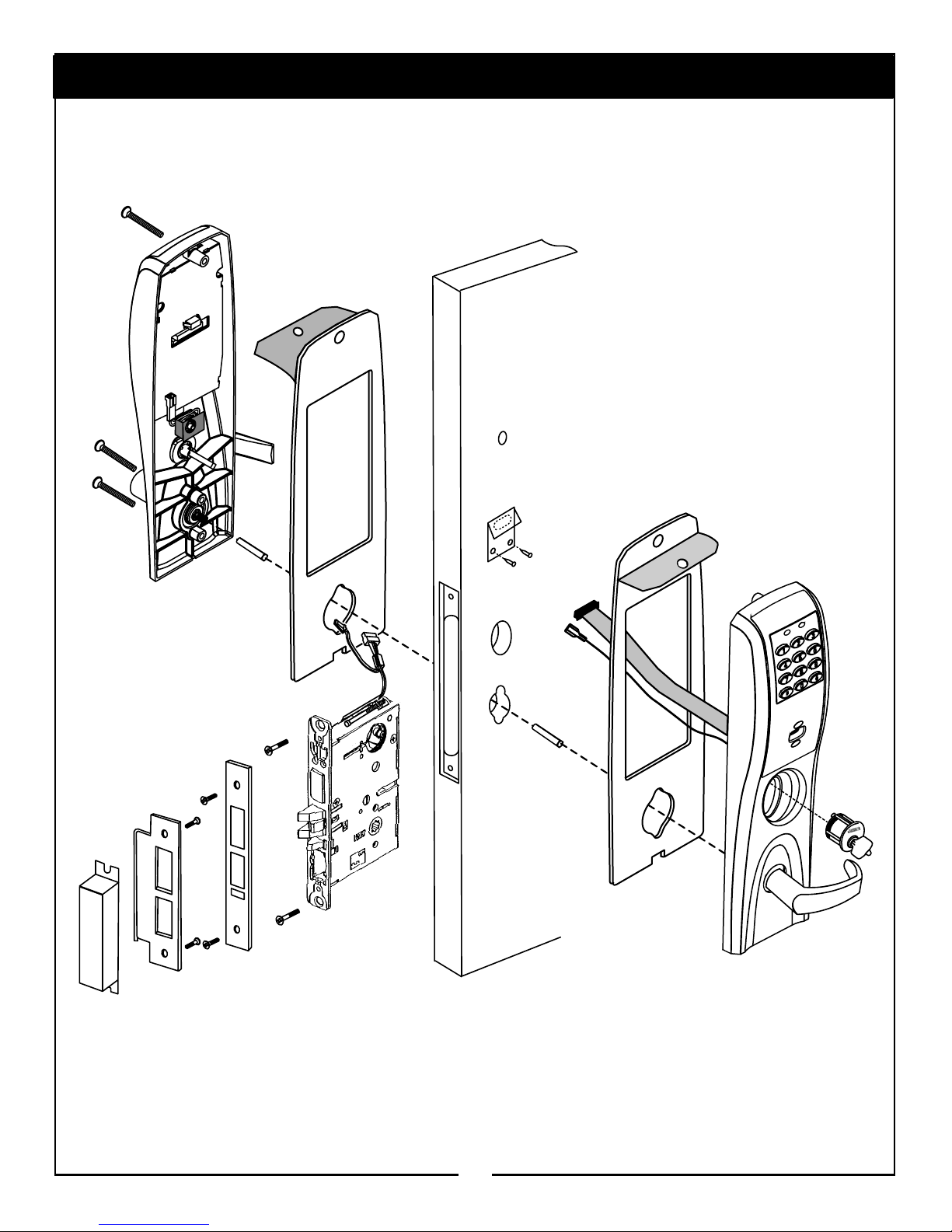
3) ML20800 TCAC2 Series Product Illustration
3

4) Installation Instructions
1
Verify Hand and Bevel of door. Illustrations shown are as viewed from the outside
or secure side of opening.
Left Hand
Hinges Left.
Open Inward.
"LH"
Left Hand
Reverse Bevel
Hinges Left.
Open Outward
Right Hand
Hinges Right.
Open Inward.
"RH"
"LHR"
2
Prep door according to supplied Corbin Russwin Inc. door marker.
Outside
of Door
Hole for ribbon cable
7/8"
L
.C of 1-1/2 Dia
1-1/2
1/8" Dia. holes
(2) required
Fire Stop Plate required
for fire rated doors
Slot
Attach Fire Stop Plate
Using self tapping screws
#8-32x1/2 long for wood &
metal doors
Right Hand
Reverse Bevel
Hinges Right.
Open Outward
"RHR"
The Optional Conduit is available
for Non Fire rated doors to provide
weather protection for exterior door
applications. It is included in the M99
Weatherseal Gasketing Kit when
ordered with the device. If ordered
separately, order part number
794F929.
Install conduit half with recessed
panel "Not For Use On Fire Door"
visible from outside of door.
Non Fire Rated Exterior Doors
install weather conduit.
(Hollow Doors Only)
O
N
F
E
I
S
U
R
O
F
T
O
N
R
E
D
O
O
R
4
3
Hole for
ribbon cable
Outside
of Door
Non Fire Rated Door
Installation Instructions
3
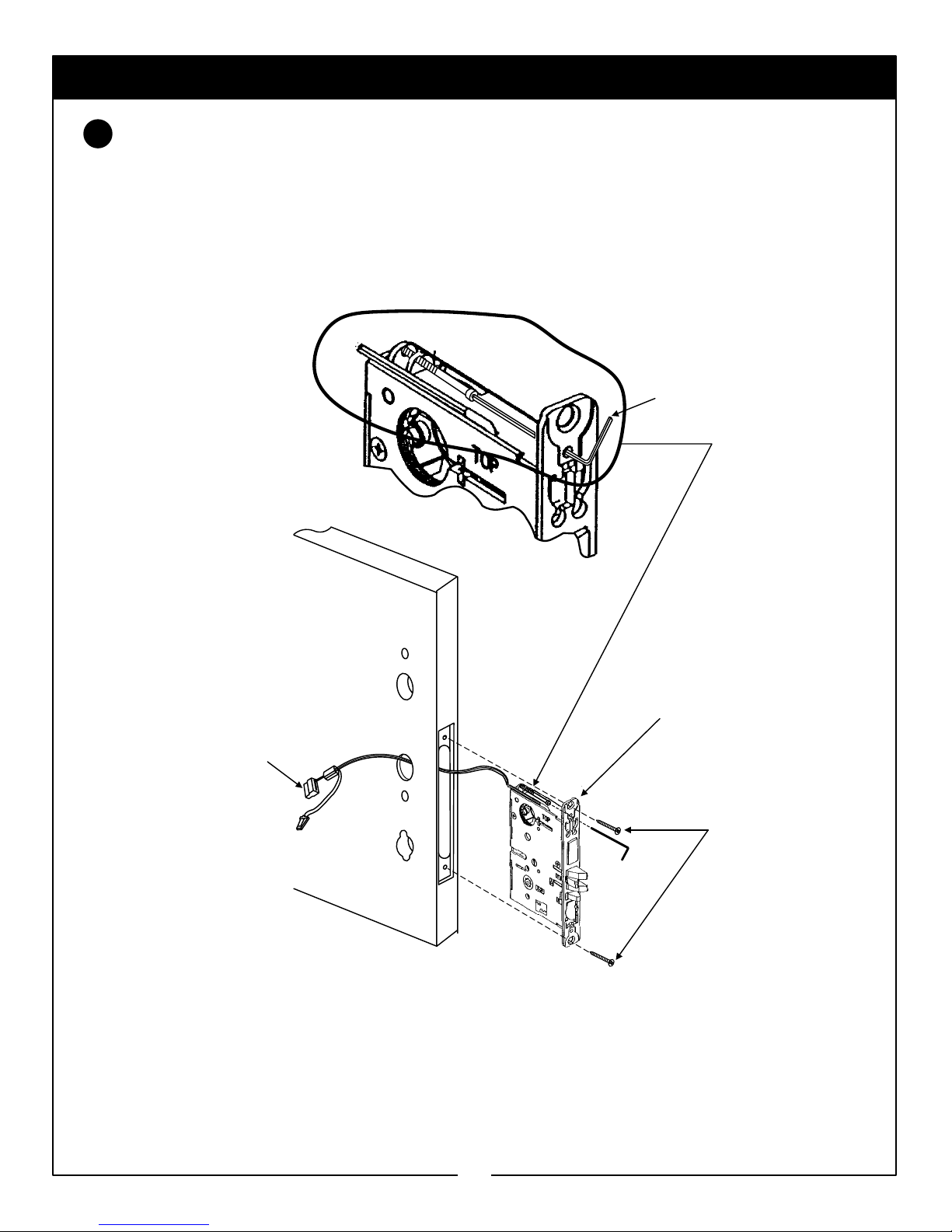
Lock Assembly Instructions
Align bevel accordingly. Engage 7/64 Allen wrench on to cap screw required for step 2
page 6. Feed connector and wires through non cylinder side of door. Insert lockbody into
mortised cutout in door and hold loosely in place with (2) #12x1" lockbody screws.
7/64 Allen Wrench
Feed Connector & wires
through non-cylinder side
Inside
of Door
Lockbody
(2) #12x1"
combination screws
5
 Loading...