

Page 1

INSTRUCTIONS FOR INSTALLATION AND USE
MONTAGE- UND GEBRAUCHSANWEISUNG
INSTRUCTIONS POUR L'INSTALLATION ET L’UTILISATION
ISTRUZIONI PER L'INSTALLAZIONE E L’USO
INSTRUCCIONES PARA INSTALACIÓN Y USO
INSTRUÇÕES DE INSTALAÇÃO Y UTILIZAÇÃO
AANWIJZING VOOR GEBRUIK EN INSTALLATIE
Page 2
ENGLISH
DESCRIPTION
The hood comes in a filtering or ducting version. With the filtering version (Fig. 1) the air and steam conveyed by the hood
are purified by the charcoal (or polyurethane) filters and recirculated in the room. With the ducting version (Fig. 2) the
steam and kitchen smells are conveyed directly to the outside through a disposal duct fitted in the wall/ceiling. Therefore,
use of charcoal (or polyurethane) filters are not necessary.
INSTALLATION
To facilitate installation, remove the grille or the grease filters (depending on the model bought) and disassemble the
front door.
Door disassembly: open the door by pulling it forwards; operating on the inside of the hood remove the 2 screws D
as illustrated in Fig. 3. Hold the tab L down and remove the door from the guides.
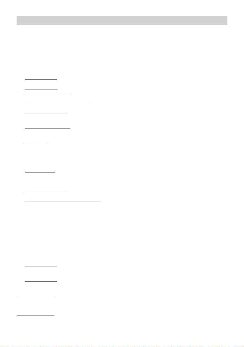
Grille disassembly: open the door pulling it forwards and push the 2 plastic catches upwards (Fig. 4).
Grease filters disassembly: open the door pulling it forwards; in correspondence to the handle, push the catch upwards
and extract the filter (Fig. 5).
Essential requirements for assembly: – set up the electrical connection. – if your hood is to be installed in the ducting
version, prepare the air evacuation opening.
With the ducting version (only for the model shown in Fig. 4) the air can be evacuated through a wall or a ceiling vent.
If air evacuation is through a wall vent, position the flange (F) on the rear and the cap (T) on the top of the apparatus (Fig.6);
if air evacuation is through a ceiling vent, do the opposite.
Before installing the hood, the following operations must be carried out (only for the model shown in Fig. 5):
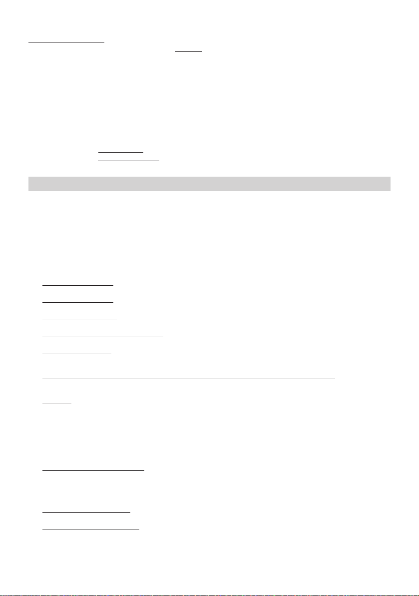
- Fig. 7: fit the flange to the hood using 2 screws (provided).
- Fig. 8: remove the polystyrene panel from inside the hood.
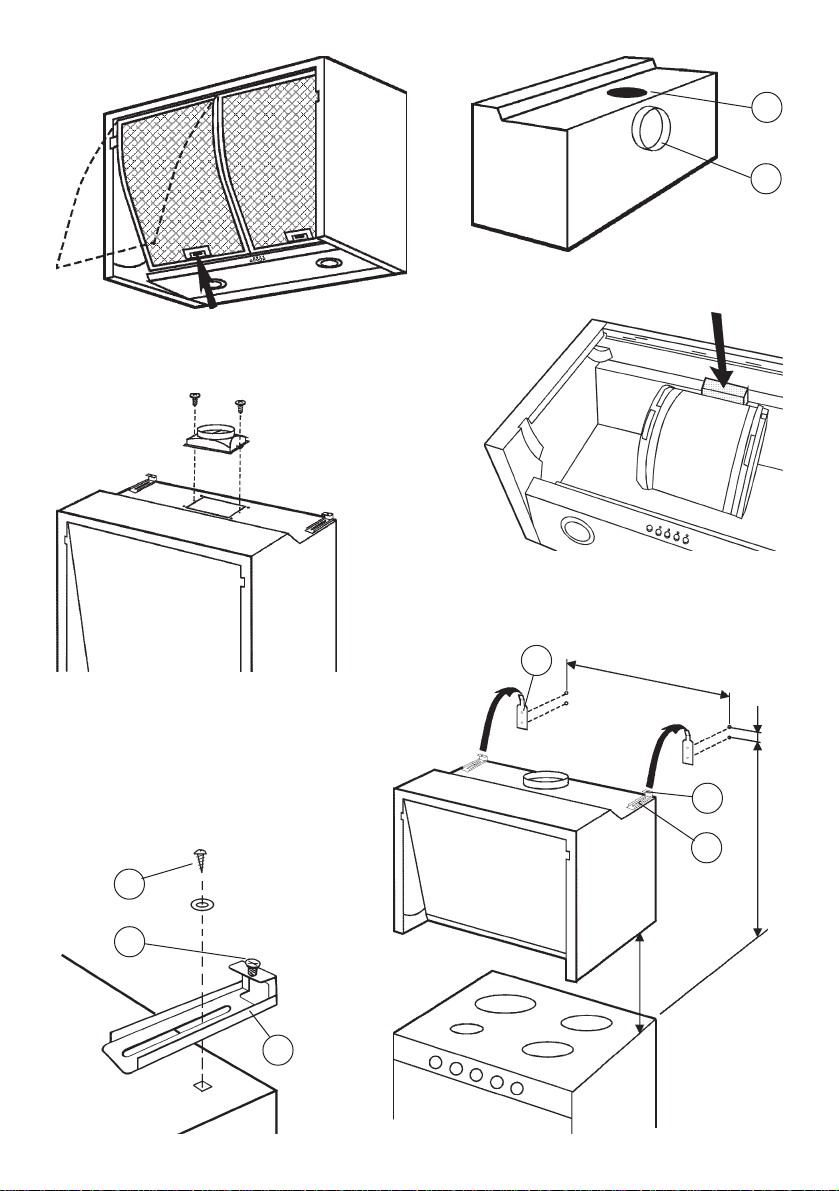
Assembling: check that the brackets L are mounted on the hood (Fig. 9); if not, fix them using 2 metrical screws (V)
with washers (all provided); also check that the 2 metric screws (M) are fitted. Bearing in mind that the distance between
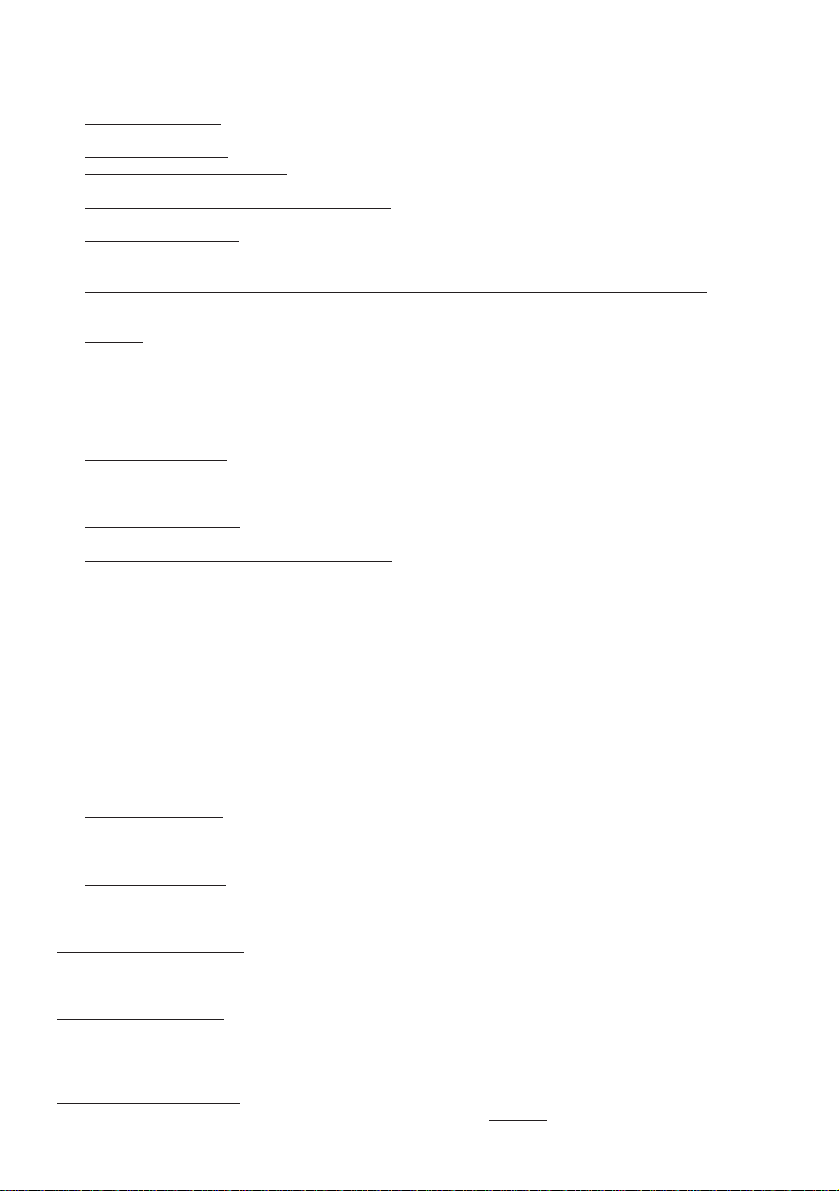
the hood and the hob must be at least 65 cm, fix the 2 brackets S (provided) to the wall using the screws and screw anchors
provided – see Fig. 10. Hook the hood to the 2 brackets; for alignment with the wall or kitchen units, the hood may be
adjusted in height by turning the screws M, and in depth by turning the screws V (Fig. 10). Before tightening all the screws,
check the distance between the hood and the wall; if necessary, use the spacer provided.
Fitting the spacer: cut the spacer to the desired size; unhook the hood from the brackets and fit the spacer to the back
of the hood with the 3 screws provided (Fig. 11).
Hook the hood back onto the wall brackets and fully tighten the screws M and V (Fig. 10). Complete the fitting by locking
the hood to the wall units by means of the 4 screws C (Fig.12).
Fitting the wooden door: cut the wooden panel to the desired size and fit it to the hood door with the 4 screws (see
dimensions in Fig. 13).
Fitting the charcoal (or polyurethane) filters. If you chose the filtering version installation, check that the carbon filters
are assembled; if they are not, assemble them as follows:
The filtering version hood is supplied with different charcoal filters according to the version:
Round charcoal filters (Fig.14T); to assemble them, hook them onto the motor and block them by making them rotate.
Polyurethane panel filters (Fig.15P); to assemble them, place them inside the grid fixing them with the supplied metal
retainers (Fig.15Q).
For the ducting version use a flexible tube to connect the hood flange to the air evacuation opening (prepared in
advance). For the filtering version use a flexible tube to connect the hood flange to the top of the wall unit.
When the installation has been completed, remount the front door and make the electrical connection.
OPERATION
For all versions the motor is operated automatically by opening and closing the front door. Open: Hood operates –
Closed: Hood does not operate.
Controls (Fig. 16): A = light switch. B = motor ON/OFF switch – speed I. C = speed II switch; pressed a second time,
the timer is activated and the motor turns off after 10’: the relevant LED flashes continuously. D = speed III switch; the timer
acts as for switch C. E = speed IV switch; the timer acts as for switch C.
Controls (Fig. 17): A = light switch; position 0: light off; position 1: light on. B = motor switch; position 0: motor off;
position 1-2-3: motor on at speed I, II and III. C = motor pilot lamp.
Grease filter/s: Depending on the version, the hood features different types of grease filters:
Modular metal filters (of the type shown in Fig. 18): these filters must be cleaned about every 30 hours of operation
(all the LEDs flash simultaneously). To remove the filters: open the door pulling it forwards and remove the filters
pushing the catch upwards in correspondence to the handle. Wash the filters with a neutral detergent. When the clean
filters have been remounted, press one of the three speed buttons to restart the counter.
Panel type metal filter (of the type shown in Fig. 19N): this is a metal filter and it is positioned inside the metal grid; the filter
must be cleaned about every 30 hours of operation (all the LEDs flash simultaneously). To remove the filter: open the door
pulling it forwards and push the 2 plastic catches upwards (Fig. 4). Remove the filter retainers (Fig. 19Q) inside the metal
grid and remove the panel type metal filter. For the filtering version, it is necessary, to reach the filter, to remove the
Page 3
polyurethane filter too.
Panel type synthetic filter (of the type shown in Fig. 20P): this filter is made of white synthetic fibres and is located inside
the metal grid; it cannot be cleaned, but must be
If the synthetic filter is not totally white, but has got coloured parts (stripes or spots), this means it is a saturation detector
filter, it should therefore be changed when the coloured parts can be seen from the outside or the apparatus. To remove
the synthetic filters: open the door pulling it forwards and push the 2 plastic catches upwards (Fig. 4). Remove the metal
filter clips (Fig. 20Q) and extract the filter . With the filtering version also the polyurethane filter needs to be removed.
In case of using the hood in the filtering version, the charcoal (or polyurethane) filters will need to be replaced
depending on use, on average every six months. The filtering hood is supplied with different types of charcoal :
Round charcoal filters (Fig. 14T); to get to the round filters, take of f the anti-grease filters pushing the catch upwards in
correspondence to the handle (Fig.5); remove the charcoal filters from the motor block making them rotate
Polyurethane panel filters (Fig.15P): to get to the polyurethane filter, remove the grille making the 2 plastic catches get
upwards (Fig.4); inside the grille, take off the metal filter catches (Fig.15Q) so that the polyurethane filter can be removed.
Lighting: depending on the model bought, refer to Fig. 21 or Fig. 22.
Fig. 21: To remove the
Fig. 22: To remove the
same type.
halogen lamps, unscrew the ring nut turning anticlockwise. Replace with lamps of the same type.
incandescent lamps, remove the light diffuser unscrewing the screw D. Replace with lamps of the
replaced from time to time according to use (at least every two months).
DEUTSCH
BESCHREIBUNG
Das Gerät kann im Umluft- oder im Abluftbetrieb verwendet werden. Beim Umluftbetrieb (Abb. 1) werden Luft und Dampf
von den Kohlefiltern (oder Polyurethanfiltern), während sie durch diese strömen, gereinigt und dann wieder in den Raum
zurückgeleitet. Im Abluftbetrieb (Abb. 2) werden Dampf und Küchengerüche durch eine Abluftleitung, die durch die Wand
oder die Decke geführt wird, direkt nach außen geleitet. In diesem Fall erübrigt sich die Verwendung der Kohle- oder
Polyurethanfilter.
INSTALLATION
Das Gitter oder die Fettfilter (je nach Modell) für eine leichtere Montage abnehmen und die frontseitige Klappe abbauen.
Demontage der Klappe: die Klappe öffnen, indem man sie nach vorne zieht; die 2 Schrauben D wie in Abb. 3 gezeigt
abdrehen. Die Lasche L niederhalten und die Klappe aus den Führungen ziehen.
Demontage des Gitters: die Klappe öffnen, indem man sie nach vorne zieht und die 2 Kunststoffriegel (Abb. 4) nach
oben schieben.
Demontage der Fettfilter: die Klappe öffnen, indem man sie nach vorne zieht; den Metallbügel beim Griff nach oben
schieben und den Filter (Abb. 5) herausziehen.
Es ist unerläßlich, daß vor der Montage: – sämtliche Vorbereitungen für den Stromanschluß getroffen werden.
– sofern das Gerät für Umluftbetrieb vorgesehen ist, die Öffnung zur Luftableitung gebohrt wird.
Bei der Absaugversion (nur für das auf Abb. 4 dargestellte Modell) kann die Luft zur Wand oder nach oben abgeleitet
werden; bei der Ableitung der Luft zur Wand den Flansch (F) auf der Rückseite und den Stopfen (T) über dem Gerät
positionieren (Abb. 6); bei der Ableitung der Luft nach oben umgekehrt vorgehen.
Vor der Montage des Gerätes ist es (nur für das auf der Abb. 5 dargestellte Modell) erforderlich:
- Abb. 7: den Flansch durch Verwendung der beiden mitgelieferten Schrauben auf das Gerät zu montieren.
- Abb. 8: die im Inneren des Gerätes befindliche Polystyrolplatte zu entfernen.
Montage : sicherstellen, daß die Haltebügel L am Gerät befestigt sind (Abb. 9); ggf. mit Feinstellschrauben (V) und
Unterlegscheiben (der Lieferung beigefügt) festspannen; desweiteren überprüfen, ob die 2 Feinstellschrauben (M)
angebracht sind. Die beiden Wandbleche S (der Lieferung beigefügt) unter Berücksichtigung, daß der Abstand des
Gerätes vom Kochfeld mindestens 65 cm sein muß, und unter Verwendung der mitgelieferten Schrauben und Dübel an
der Wand befestigen - siehe Abb. 10. Das Gerät an die 2 Wandbleche einhaken; durch Verdrehen der Regulierungsschrauben
M und V (Abb. 10) kann das Gerät senkrecht bzw. waagerecht ausgerichtet werden. Vor dem endgültigen Festspannen
der Schrauben ist der Abstand des Gerätes von der Wand zu überprüfen; wenn nötig, den mitgelieferten Abstandhalter
einfügen.
Befestigung des Abstandhalters: den Abstandhalter auf das richtige Maß zuschneiden, das Gerät von den
Wandblechen aushaken und den Abstandhalter mit den 3 mitgelieferten Schrauben (Abb. 11) auf der Rückseite des Geräts
befestigen.
Das Gerät wieder an den Wandblechen einhaken und die Regulierungsschrauben M und V (Abb. 10) fest anziehen.
Nun kann das Gerät mittels der 4 Schrauben C (Abb. 12) an den Hängeschränken festgespannt werden.
Befestigung der Holzklappe: die Holzplatte maßgerecht zuschneiden und mit 4 Schrauben an der Geräteklappe
befestigen (vgl. hierzu die in Abb. 13 angegebenen Maße).
Installierung der Aktivkohlefilter (oder Polyurethanfilter). Falls die Dunstabzugshaube in Filterversion montiert ist,
muss überprüft werden, ob die Aktivkohlefilter eingesetzt sind; falls sie nicht montiert sind, sind sie auf folgende Art und
Weise einzusetzen:
Je nach Version, sind die Dunstabzugshauben in Filterversion mit unterschiedlichen Aktivkohlefilterarten ausgestattet:
Runde Aktivkohlefilter (Abb. 14 T); um sie zu montieren, müssen sie in den Motorkomplex
eingehängt werden, dann mit
Page 4

einer Drehbewegung einrasten lassen.
Filterpaneel aus Polyurethan (Abb. 15 P); um dieses zu montieren, muss es im Inneren des Gitters positioniert und mit
Hilfe der mitgelieferten Filterklemmen aus Metall befestigt werden (Abb. 15 Q).
Für den Abluftbetrieb ist ein flexibles Rohr an den Geräteflansch anzuschließen und zur vorgebohrten Abluftöffnung
zu führen; für den Umluftbetrieb wird ein flexibles Rohr vom Geräteflansch zum oberen Teil des Hängeschrankes geleitet.
Nach erfolgter Montage die vordere Klappe wieder montieren und den Stromanschluß ausführen.
ARBEITSWEISE
Sowohl in der Version für Umluft- als auch für Abluftbetrieb wird der Motor beim Öffnen der frontseitigen Klappe angesteuert
und beim Schließen gestoppt.
Steuerungstasten der Abb. 16: A = Taster für die Beleuchtung. B = ON/OFF Taster für die 1. Schaltstufe der
Motorgeschwindigkeit. C = Taster für die 2; Schaltstufe der Motorgeschwindigkeit; Bei erneuter Betätigung dieses Tasters
wird der Timer aktiviert, der nach 10 Sek. den Motor stoppt: die betreffende Led blinkt während der ganzen Zeit. D = Taster
für die 3; Schaltstufe der Motorgeschwindigkeit; Der Timer funktioniert wie bei Schalter C. E = Taster für die 4; Schaltstufe
der Motorgeschwindigkeit; Der Timer funktioniert wie bei Schalter C.
Steuerungstasten der Abb. 17: A = Schalter für die Beleuchtung; Stellung 0: Beleuchtung aus; Stellung 1:
Beleuchtung ein. B = Motorschalter; Stellung 0: Motor aus; Stellung 1-2-3: erste, zweite und dritte Schaltstufe. C = Led
Motorbetrieb.
Fettfilter: je nach Version sind die Dunstabzugshauben mit unterschiedlichen Fettfilterarten ausgestattet:
Modulare Metallfilter (von der in Abb. 18 dargestellten Art): die Fettfilter müssen ungefähr alle 30 Betriebsstunden gereinigt
werden (alle Kontrolleuchten leuchten gleichzeitig). Zur Entfernung des Filters: die Klappe nach vorne ziehen und öffnen,
dann die Filterklemme nach oben in Richtung des Griffs drücken und die Filter entnehmen. Die Filter mit einem
Neutralreiniger säubern. Nach der erneuten Montage der gereinigten Filter, eine der drei Geschwindigkeitstasten drücken,
um die Zählfunktion der Betriebsstunden neu zu starten.
Filterpaneel aus Metall (von der in Abb. 19 N dargestellten Art): dieser Filter ist aus Metall und befindet sich im Inneren
des Metallgitters; er muss ungefähr alle 30 Betriebsstunden gereinigt werden (alle Kontrolleuchten leuchten gleichzeitig).
Zur Entfernung des Filters: die Klappe nach vorne ziehen und öffnen, dann die beiden Filterklemmen aus Plastik nach oben
drücken (Abb. 4). Danach die Filterklemmen aus Metall entfernen (Abb. 19 Q) und den Filter herausnehmen. Bei der
Dunstabzugshaube in Filterversion muss, vor der Entfernung des Fettfilters, auch der Polyurethanfilter entnommen
werden.
Filterpaneel aus synthetischer Faser (von der in Abb. 20 P dargestellten Art): diese Filterart besteht aus einer synthetischen
weissen Faser und befindet sich im Inneren des Metallgitters; er kann nicht gereinigt werden, sondern er muss, je nach
Intensität des Gebrauchs, mehr oder weniger häufig
synthetische Filter nicht vollständig weiss ist, sondern an einigen Stellen farbig ist (gestreift oder punktörmig), handelt es
sich um einen Filter, der den Sättigungsgrad anzeigt – er muss ausgewechselt werden, wenn die farbigen Stellen von
aussen her sichtbar werden. Zur Entfernung der synthetischen Filter: die Klappe nach vorne ziehen und öffnen, dann die
beiden Filterklemmen aus Plastik nach oben drücken (Abb. 4). Danach die Filterklemmen aus Metall entfernen (Abb. 20
Q) und den Filter herausnehmen. Bei der Dunstabzugshaube in Filterversion muss auch der Polyurethanfilter entnommen
werden.
Wenn die Dunstabzugshaube in Filterversion verwendet wird, müssen die Aktivkohlefilter (oder die Polyurethanfilter)
je nach der Intensität des Gebrauchs ausgewechselt werden; im Durchschnitt alle 6 Monate. Je nach Geräteversion, ist
die Umlufthaube mit unterschiedlichen Aktivkohlefiltertypen ausgestattet:
Runde Aktivkohlefilter (Abb. 14 T); um Zugang zu den runden Aktivkohlefiltern zu bekommen, müssen die Fettfilter entfernt
werden, indem die Filterklemmen nach oben in Richtung des Griffs gedrückt werden (Abb. 5); danach die Aktivkohlefilter
durch eine Drehbewegung aus dem Motorkomplex aushaken.
Filterpaneel aus Polyurethan (Abb. 15 P); um Zugang zum Polyurethanfilter zu bekommen, muss das Gitter entfernt
werden, indem die beiden Plastikfilterklemmen nach oben gedrückt werden (Abb. 4); im Inneren des Filters die
Filterklemmen aus Metall entfernen (Abb. 15 Q), so dass der Polyurethanfilter freigelegt wird.
Beleuchtung: Gehen Sie bitte, je nach Ihrem Modell, gemäß Zeichnung 21 oder Zeichnung 22 vor. Abb. 21: zur
Abnahme der
Typs austauschen. Abb. 22: zur Abnahme der
durch eine solche gleichen Typs austauschen.
Halogenlampen die Nutmutter gegen den Uhrzeigersinn drehen. Die Lampe durch eine solche gleichen
ausgewechselt werden (mindestens alle zwei Monate). Wenn der
Glühlampen die Deckenkappe abschrauben (Schraube D). Die Lampe
FRANCAIS
DESCRIPTION
L’appareil est disponible en version recyclage ou en version aspirante. Sur la version recyclage (Fig. 1) l’air et les vapeurs
acheminés par l’appareil sont dépurés par les filtres à charbon (ou polyuréthanne) et remis en circulation dans le local. Sur
la version aspirante (Fig. 2), les vapeurs et les odeurs de cuisine sont acheminées directement vers l’extérieur, au moyen
d’un conduit d’évacuation, à travers le mur/plafond. Par conséquent, l’utilisation de filtres à charbon (ou polyuréthanne)
n’est plus nécessaire.
Page 5
INSTALLATION
Pour faciliter l’installation, enlever la grille ou les filtres à graisse (en fonction du modèle acheté) et démonter le cache
antérieure.
Démontage du cache : ouvrir le cache en le tirant en avant, en opérant depuis l’intérieur de l’appareil, enlever les deux
vis D comme indiqué Fig. 3. Maintenir la languette L abaissée et extraire le cache des guides.
Démontage de la grille : ouvrir le cache en le tirant en avant et déplacer vers le haut les 2 butées en plastique (Fig.4).
Démontage des filtres à graisse : ouvrir le cache en le tirant en avant; en face de la poignée, pousser la butée vers
le haut et extraire le filtre (Fig. 5).
Conditions requises essentielles pour le montage: – prédisposer le branchement électrique. – en cas d’appareil
version aspirante, prédisposer l’orifice d’évacuation d’air.
Pour la version aspirante (uniquement pour le modèle représenté sur la Fig. 4) l‘air peut être évacué par le mur ou
vers le haut; si l‘évacuation de l‘air est sur le mur, il faut placer le flasque (F) sur l‘arrière et le bouchon (T) sur l‘appareil
(Fig. 6); si l‘évacuation de l‘air est vers le haut, faire le contraire.
Avant d’installer l’appareil, il est nécessaire de (uniquement pour le modèle représenté sur la Fig. 5) :
- Fig. 7: monter la bride à l’appareil en utilisant les vis (fournies).
- Fig. 8: enlever le panneau de polystyrène situé à l’intérieur de l’appareil.
Montage :vérifier que les brides L soient montées à l’appareil (Fig. 9); dans le cas contraire, les fixer en utilisant les
deux vis métriques (V) avec rondelle (tous en dotation); de plus, vérifier que les 2 vis métriques (M) soient montées. Etant
donné que la distance entre l’appareil et le plan de cuisson doit être de 65 cm minimum, fixer les deux brides S (en dotation)
au mur au moyen des vis et chevilles (en dotation) - voir Fig. 10. Accrocher l’appareil aux 2 brides; pour réaliser l’alignement
avec des éléments suspendus ou les meubles de la cuisine, il est possible de régler l’appareil en hauteur en agissant sur
les vis M, et en profondeur en agissant sur les vis V (Fig. 10). Avant de serrer complètement les vis, vérifier la distance
entre l’appareil et le mur, si nécessaire, utiliser l’entretoise en dotation.
Fixation de l’entretoise: couper l’entretoise à la mesure désirée, décrocher l’appareil des brides murales et fixer
l’entretoise à l’arrière de l’appareil à l’aide des 3 vis en dotation (Fig. 11).
Accrocher de nouveau l’appareil aux brides murales et serrer complètement les vis M et V (Fig. 10). Procéder à la
fixation définitive en bloquant l’appareil aux éléments suspendus au moyen des 4 vis C (Fig. 12).
Fixation du cache en bois: couper le panneau en bois à la mesure désirée puis le fixer à l’aide des 4 vis au cache de
l’appareil (voir mesures Figure 13).
Installation des filtres à charbon (ou polyuréthanne). Si vous avez choisi d’installer votre hotte version filtrante, vérifiez
que les filtres à charbon soient installés; s’ils ne le sont pas, assemblez-les de la façon suivante:
suivant les versions, votre hotte filtrante vous est fournie avec différents types de filtres à charbon:
Filtres è charbon ronds (Fig.14T) ; pour les installer, accrochez-les au groupe moteur en les bloquant grâce à un
mouvement de rotation.
Filtre en panneau de polyuréthanne (Fig. 15P); pour l’installer, placet-le à l’intérieur de la grille, en le bloquant grâce aux
arrêts métalliques fournis (Fig. 15Q).
En ce qui concerne la version aspirante, utiliser un tuyau flexible pour relier la bride de l’appareil à l’orifice d’évacuation
de l’air (précédemment effectué); en ce qui concerne la version filtrante, utiliser un tuyau flexible pour relier la bride de
l’appareil au sommet de l’élément suspendu.
Une fois l’installation terminée, remonter le cache antérieur et effectuer le branchement électrique.
FONCTIONNEMENT
Toutes les versions sont réalisées avec fonctionnement automatique du moteur par ouverture et fermeture du cache
frontal. Ouvert: l’appareil est en service - Fermé: l’appareil ne fonctionne pas.
Commandes (Fig. 16): A = interrupteur allumage éclairage. B = interrupteur mise en service ON/OFF moteur à la
1ère vitesse. C = interrupteur 2ème vitesse; appuyer une seconde fois pour activer la minuterie, le moteur s’éteindra 10’
plus tard : la DEL correspondante clignote pendant toute cette durée. D = interrupteur 3ème vitesse; la minuterie agit
comme pour l’interrupteur C. E = interrupteur 4ème vitesse; la minuterie agit comme pour l’interrupteur C.
Commandes (Fig. 17): A = interrupteur allumage éclairage; position 0 : éclairage en service; position 1 : éclairage
éteint. B = interrupteur moteur; position 0: moteur à l’arrêt; position 1-2-3: moteur en service à la première, seconde et
troisième vitesse. C = voyant témoin de fonctionnement du moteur.
Filtre/s à graisse : En fonction des versions, la hotte est équipée de différents types de filtre à graisse :
Filtres métalliques modulaires (du type indiqué en Fig. 18): les filtres à graisse doivent être nettoyés environ toutes les 30
heures de fonctionnement (toutes les DELS clignotent simultanément). Pour enlever le filtre: ouvrir le cache en le tirant
en avant; en face de la poignée, pousser la butée vers le haut et extraire le filtre. Laver les filtres avec une lessive neutre.
Une fois les filtres propres remontés, appuyer sur l’une des trois touches de vitesse pour faire repartir le comptage.
Filtre métallique à panneau (du type indiqué en Fig. 19N): ce filtre est métallique et est positionné à l’intérieur de la grille
métallique; le filtre doive être nettoyé environ toutes les 30 heures de fonctionnement (toutes les DELS clignotent
simultanément). Pour enlever le filtre: ouvrir le cache en le tirant en avant et déplacer vers le haut les 2 butées en plastique
(Fig. 4). Enlevez les arrêts en métal (Fig. 19Q) et ôtez le filtree. Dans la version filtrante, pour accéder au filtre, il faut enlever
le filtre en polyuréthanne aussi.
Filtre synthétique à panneau (du type indiqué en Fig. 20P): ce filtre est en fibre synthétique (blanc) et est positionné à
l’intérieur de la grille métallique; il ne peut pas être nettoyé mais doit être
(au moins tous les deux mois). Si le filtre synthétique n’est pas complètement blanc, mais a des zones colorées (raies ou
remplacé périodiquement, en fonction de l’usage
Page 6

pois), il s’agit d’un filtre à révélation de saturation, remplacez le donc quand les zones colorées sont visibles de l’extérieur
de votre appareil. Pour enlever les filtres synthétique: ouvrir le cache en le tirant en avant et déplacer vers le haut les 2
butées en plastique (Fig. 4). Enlevez les arrêts en métal (Fig.20Q) et sortez le filtre. Dans la version filtrant il faut enlever
le filtre en polyuréthanne aussi.
En cas d’appareil en version recyclage, il est nécessaire de remplacer les filtres à charbon (ou polyuréthanne)
en fonction de l’utilisation, en moyenne tous les 6 mois. En fonction des versions, la hotte est équipée de différents types
de filtre à charbon:
Filtres à charbon ronds (Fig.14T); pour atteindre les filtres à charbon ronds, enlevez les filtres anti-graisse en poussant
l’arrêt vers le haut en correspondance avec le poignée (Fig.5)); décrocher les filtres au charbon du groupe moteur en les
faisant pivoter.
Filtre en panneau de polyuréthanne (Fig.15P) ; pour atteindre le filtre en polyuréthanne, enlevez la grille en poussant les
deux arrêts en plastique vers le (Fig.4); enlevez, à l’intérieur de la grille, les arrêts du filtre en métal (Fig. 15Q) afin de libérer
le filtre en polyuréthanne.
Eclairage: en fonction du modèle acheté, consulter la Fig. 21 ou la Fig. 22. Fig. 21 : pour démonter les
halogènes, dévisser le collier dans le sens contraire des aiguilles d’une montre. Les remplacer par des ampoules de même
type. Fig. 22: pour démonter les
par des ampoules de même type.
ampoules à incandescence, enlever le plafonnier en dévissant la vis D. Les remplacer
ampoules
ITALIANO
DESCRIZIONE
L’apparecchio può essere in versione filtrante o in versione aspirante. Nella versione Filtrante (Fig. 1) l’aria e i vapori
convogliati dall’apparecchio, vengono depurati dai filtri al carbone (o poliuretano) e rimessi in circolazione nell’ambiente.
Nella versione Aspirante (Fig. 2) i vapori e gli odori di cucina, vengono convogliati direttamente verso l’esterno, tramite
un condotto di evacuazione, attraverso la parete/soffitto. Pertanto non è più necessario l’uso di filtri al carbone (o poliuretano).
INSTALLAZIONE
Per facilitare l'installazione, togliere la griglia o i filtri antigrasso (a seconda del modello da voi acquistato) e smontare
lo sportello anteriore.
Smontaggio dello sportello: aprire lo sportello tirandolo in avanti; operando dall'interno dell'apparecchio togliere le 2
viti D come illustrato in Fig. 3. Tenere abbassata la linguetta L e sfilare lo sportello dalle guide.
Smontaggio della griglia: aprire lo sportello tirandolo in avanti e spostare verso l'alto i 2 fermi in plastica (Fig. 4).
Smontaggio dei filtri antigrasso: aprire lo sportello tirandolo in avanti; in corrispondenza della maniglia, spingere il
fermo verso l'alto ed estrarre il filtro (Fig. 5).
Requisiti essenziali per il montaggio: – predisporre il collegamento elettrico. – se il vostro apparecchio deve essere
istallato in versione Aspirante, predisporre il foro evacuazione aria.
Nella versione aspirante (solo per il modello rappresentato in Fig. 4), l'aria puo' essere evacuata a parete oppure verso
l'alto; se l'evacuazione dell'aria è a parete, posizionate la flangia (F) sul retro ed il tappo (T) sopra l'apparecchio (Fig. 6);
se l'evacuazione dell'aria è in alto, fate il contrario.
Prima di installare l’apparecchio, è necessario (solo per il modello rappresentato in Fig. 5):
- Fig. 7: montare la flangia all’apparecchio utilizzando 2 viti (in dotazione).
- Fig. 8: togliere il pannello di polistirolo situato all’interno dell’apparecchio.
Montaggio : verificare se le staffe L sono montate all'apparecchio (Fig. 9); nel caso fissarle utilizzando 2 viti metriche
(V) con rondelle (tutto in dotazione); inoltre verificare che siano montate le 2 viti metriche (M). Considerando che la distanza
tra l'apparecchio ed il piano di cottura deve essere minimo 65 cm, fissare le 2 staffe S (in dotazione) alla parete mediante
le viti ed i tasselli (in dotazione) - vedi Fig. 10. Agganciare l'apparecchio alle 2 staffe; per l'allineamento ai pensili o ai mobili
della vostra cucina, potete regolare l'apparecchio in altezza operando sulle viti M, e in profondità operando sulle viti V
(Fig.10). Prima di serrare del tutto le viti, verificare la distanza tra l'apparecchio e la parete; se necessario dovrete utilizzate
il distanziale in dotazione.
Fissaggio del distanziale: tagliare il distanziale alla misura desiderata; sganciare l'apparecchio dalle staffe a parete
e fissare il distanziale sul retro dell'apparecchio con le 3 viti in dotazione (Fig. 11).
Riagganciare l'apparecchio alle staffe a parete e serrare del tutto le viti M e V (Fig. 10). Procedere al fissaggio definitivo
bloccando l'apparecchio ai pensili tramite le 4 viti C (Fig. 12).
Fissaggio dello sportello in legno: tagliare il pannello in legno alla misura desiderata e fissarlo con 4 viti allo sportello
dell'apparecchio (vedi misure nella Figura 13).
Installazione dei filtri al carbone (o poliuretano). Nel caso abbiate scelto l’installazione in versione filtrante, verificare
che siano installati i filtri carbone; nel caso non siano installati procedere col montaggio come segue:
a seconda delle versioni, la cappa filtrante è fornita con diversi tipi di filtro carbone:
Filtri al carbone rotondi (Fig. 14T); per montarli, agganciarli al gruppo motore bloccandoli con un movimento rotatorio.
Filtro in poliuretano a pannello (Fig. 15P); per montarlo, posizionatelo all’interno della griglia, fermandolo con i fermafiltri
metallici in dotazione (Fig. 15Q).
Per la versione aspirante utilizzare un tubo flessibile che colleghi la flangia dell'apparecchio al foro evacuazione aria
Page 7

1A
1B
2A
3
2B
4
D
L
Page 8
56
T
F
8
7
10
9
V
M
L
S
560 - 860
55
M
940
V
min
65cm
Page 9

11 12
13
268
72
C
P
Q
14
T
A16B C
15
17
A
C
B
D
E
Page 10

18
20
21
19
P
Q
N
Q
22
D
04306521/1 - GI198 sen.nor.
 Loading...