

Page 1

Instruction Manual
Model: CCV3HL60
PLACA VITROCERAMICA
Manual de Instrucciones
Modelo: CCV3HL60
Á
Page 2

Dear customer,
Thank you for purchasing the our ceramic hob.
Our product can serve you many years to your satisfaction.
Please read this instructions manual carefully before using and installation.
Keep it in a good place after reading for future reference.
Thank you again for your purchase of our ceramic hob, and wish
you to enjoy the pleasure brought about by it.
Product Introduction
The ramic hob can meet dif ferent
CCV3HL60
kind
s of cuisine demands because of resistance wire heating, microcomputerized control and multi-power selection, really the optimal choice
for modern families.
The ceramic hob centers on customers and adopts personalized
desig
n. The hob has safe and reliable performances, making your life
comfortable and enabling to fully enjoy the pleasure from life.
microcomputer ce
Working Principle
The microcomputer ceramic hob directly employs
C C V3H L60
resistance wire heating, and realizes power regulation with the microcomputer
controlling different heating time and closing time of the resistance wire.
Safety
High temperature protection
The temperature sensor mounted on the radiant electric the temperature
insid
e the cooker from time to time. When an excessive temperature is
detected, the cooking plate will be directly disconnected and stop power
output.
1
Page 3
Safety
2
Residual heat indicators
After using the hob, waste heat remains in the heating area. The
power nixie tube shows the code “H”, warning to be away from the
heating area.
Auto shut down protection
3
During the hob working, it is shut off automatically when the default
timing reach by the program if without operating. If several heating
zones work simultaneously, the hob will be automatically shut off when
anyone heating area reaches it’s default timer. The default working
timer for various power levels are shown in the table below:
Power level 1 2 3 4 5 6 7 8 9
Default workin
time(hour)
g
8 8 8 4 4 4 2 2 2
Installation
1
Selection of installation equipment
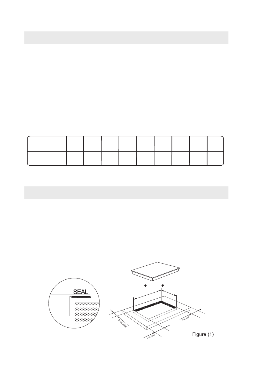
Drill holes on the table surface according to the sizes shown in the drawing.
For
the purpose of installation and use, a minimum of 50 mm space shall
be preserved around the hole
sure the thickness of the table surface is at least 30mm. Please select
Be
hea
t-resistant table material to avoid larger deformation caused by the heat
radiation from the hotplate
As shown in Figure (1
)
.
.
56cm
49cm
2
Page 4
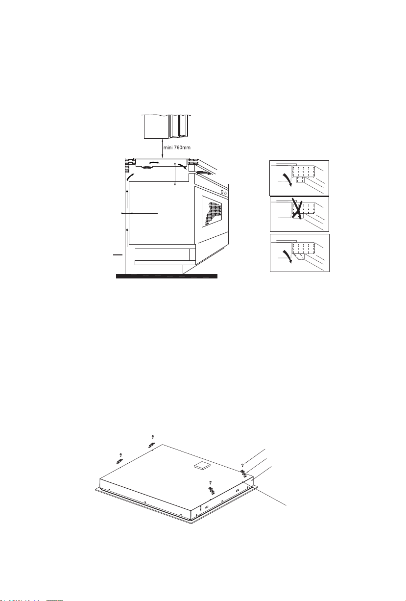
Under any circumstances, make sure the ceramic hob is well
2
ventilated and the air inlet and outlet are not blocked.
Ensure the ceramic hob is in good work state. As shown in
Figure (2)
Air exit
mini 5 cm
mini 2 cm
mini 5 mm
Air intak e
Figure (2)
Note: The safety distance between the ceramic hob and the cupboard
above the hotplate should be at least 760mm.
Fix the hob on the table by screw four brackets on the bottom of hob
3
(see picture) after installation. Adjust the bracket position to suit for
different table top thickness.
w
e
t
r
e
c
k
s
c
a
r
b
e
s
a
b
s
c
r
e
w
h
o
l
e
3
Page 5
Cautions
1.
The ceramic hob must be installed by qualified personnel
or technicians. We have professionals at your service. Please
never conduct the operation by yourself.
2.
The ceramic hob shall not be mounted to cooling equipment,
dishwashers and rotary dryers.
3.
The ceramic hob shall be installed such that better heat radiation
can be ensured to enhance its reliability.
4.
The wall and induced heating zone above the table surface shall
withstand heat.
5.
To avoid any damage, the sandwich layer and adhesive must be
resistant to heat.
6.
A steam cleaner is not to be used.
A board is must to be installed underneath the hob.
7.
4
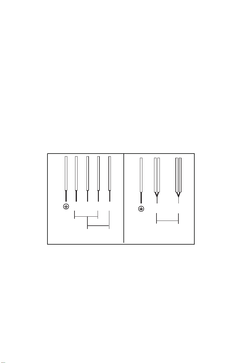
Power line connection
Th
e socket shall be connected according to the relevant standard
or connected to a single-pole cut-out. 30 minimum supply.
The method of connection is shown in Figure (3):
wolley
eulb
neerg
N2 N1 L2 L1
220-240V
PE
connect to the main power supply
220-240V 2+2N~
yerg
nw
o
rb
220-240V
kca
lb
wolley
eulb
nee
r
g
N L
PE
connect to the main power supply
220-240V
y
erg
220-240V
nwo
kc
alb
rb
The installer must ensure that the correct electrical connection has
been made and that it complies with wiring rules.
Figure (3)
If the cable is damaged or to be replaced, the operation must be
carried out the by after-sale agent with dedicated tools to avo
any accidents.If the appliance is being connected directly to t
mains an omnipolar circuit-breaker must be installed wit
minimum opening of 3mm between contacts
. The installer must
h a
ensure that the correct electrical connection has been made and
that it complies with wiring rules.
The cable must not be bent or compressed.
The cable must be checked regularly and replaced by authoris
technicians on
ly.
id
he
ed
4
Page 6
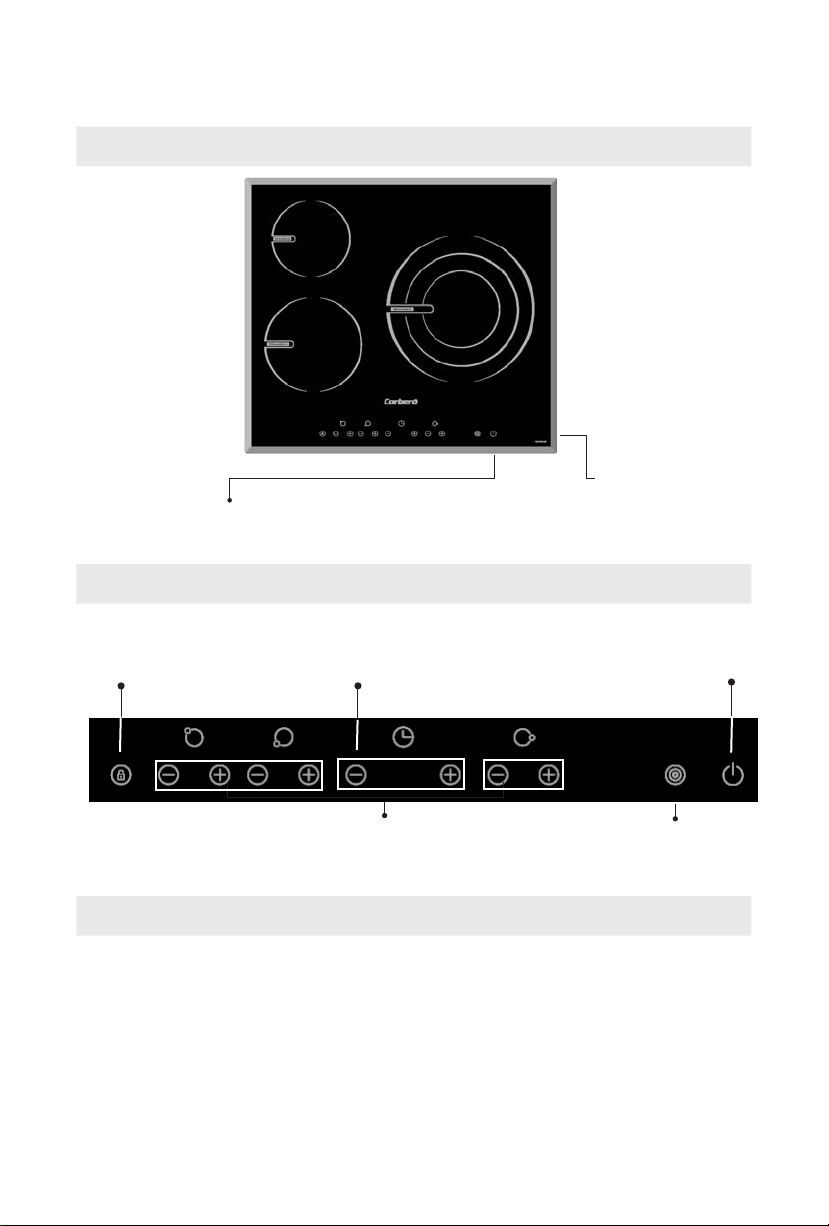
The ceramic hob appearance
1
Glass plate
3
2
ON/OFF
Schematic diagram of the control panel
Lock
Timer regulating key
Power regulating key
Control panel
On/Off
Treble zone
Instructions for Use
Put the pot in the center of the heating zone.
Preparation before using
Afte
r power on, the buzzer keep once, all the indicators light up for 1 second
n go out, indicating the ceramic hob enters into standby mode.
the
5
Page 7
Operation Instructions:
Switch on the ceramic hob
Press the “On/Off” key, the hob go to stanby mode,all the indicator
shows “-”.If the ceramic plate is hot,the indicator shows “-” and “H”
alternately.
Press the “-” or “+“ to decrease or increase the power level. If the
power level returns to 0, the zone switch off.
Note: 1. In standby working mode, press the“ON/OFF ” key
the hob switch off.
2 . In the standy mode,if no any other action within 1
minute,the hob switch off.
3. Every heating zone is independent each other.
Treble loop function
The hob is fitted with double zone
Active the double zone
If you want to use bigger heating zone, press the “ ” when the hob
is in working mode .
Press the " " for the first time, it works in double loop working mode.
Press the " " for the second time, it works in treble loop working mode.
Press the " " for the third time, it returns to the single loop working
mode.
Note : 1.The function is available in the 3# heating zone.
2.You can change the power level from 1 to 9.
3. When the Double loop function is available, the corresponding
indicator shows “P”
ON/OFF
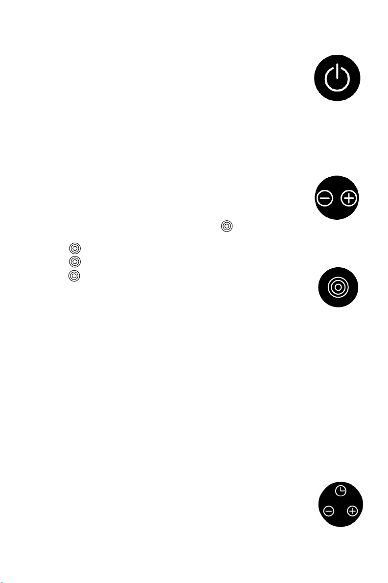
Timing function
Cooking timer
Select first one cooking zone by press the “-” or “+” of the
corresponding heating zone,then the cooking zone display flashing.
Then adjust timer by +/- of timer, after the timer indicator flashing 5
seconds, the timer is confirmed. You will find a red dot display at the
cooking zone indicator you selected. It reminds you this cooking zone
is with a timer setting. When cooking timer expire,relative cooking zone
will be swhitch off automatically. Cooking timer only works for one
cooking zone at the same time.
Minute reminder
Timer can be used as a Minute reminder. Active timer by press “+”or ”-”
key, display will flash , adjust timer by press +/- key, single touch
+/- key will increase or decrease 1 Minute, by press and hold +/- key
you can adjust time by 10 Minutes. After 5 seconds, display will stop
flashing, Minutes reminder start count down. Buzzer will bips for 30
seconds when setting time reached and the display shows "- -",
cooking process and power setted will not be affected by Minute reminder.
6
Page 8

Timing cancellation:
If press the "+" and "-" simultaneously, the timing can be
cancelled automatically, with the timing indicator showing “--”.
Lock function : To ensure the safety of children, the
hob is provided with the function of lock function.
tivating the lock function : When the lock is
Ac
th
deactivated
, touch the “Lock” key to activate
e
Lock function, and the timer indicator shows “Lo”,and the
indicator lamp will light up.
The rest keys disabled except the "ON/OFF" key.
Deactivating the lock function : When the hob in the
locking mode, you can deactivate the lock function
by holding the “lock” key for a while.
The power of each heating zone are shown as follow:
Lock key
Heating zone 1 2
Inner
Power(w)
18001200
1050W
Safety Reminding and Maintenance
A dedicated power protection
air switch must be used.
Never use the ceramic cooker
ho b in high temper ature
environments such as near a
gas stove or kerosene stove.
7
3
double-loop three-loop
1950W
2700W
Do not put any detergents or
flammable materials in the
equipment installed under the
ceramic hob.
Page 9

Me talli c obj e cts such as
knives, forks,spoons and lids
should not be placed on the
hotplate since they can get
hot.
For sealed foods such as
canned goods, please do not
heat them before opening their
covers so as to avoid any
dangers of explosion due to
heating expansion.
If the supply cord is damaged
, it must be replaced by the
manufacturer, its service agent
or similarly qualified persons
in order to avoid a hazard.
Do not place rough or uneven
app l i an c e s, w hi c h m a y
damage the ceramic surface.
Never ha ve the cer amic
cooker hob to work without
food inside, otherwise its
operational performance may
be affected and danger may
happen.
DISPOSAL: Do not dispose this
product
as unsorted municipal
waste.
Collection of such waste
separately
is necessary.
for special treatment
the surface is cracked, swith
If
off the appliance to avoid the
possibility of electric shock.
After being used for a long
ti m e, t he corr espon ding
heating zone of the ceramic
cooker hob is till hot. Never
touch the ceramic surface to
avoid burning.
Indoor use only.
Never wash the induction
cooker with water directly to
avoid danger.
Keep electrical appliance out
of reach from children or
form person. Do not let them
in
use the appliances without
supervision.
Clean the ceramic hob
on a regular basis to prevent
foreign matters from entering
the fan thus influencing the
normal operation.
8
Page 10

1. This appliance is not intended for use by persons (including children) with reduced
physical, sensory or mental capabilities, or lack of experience and knowledge,
unless they have been given supervision or instruction concerning use of the
appliance by a person responsible for their safety.
Children should be supervised to ensure that they do not play with the appliance.
2. If the supply cord is damaged, it must be replaced by the manufacturer, its service
agent or similarly qualified persons in order to avoid a hazard.
3. A steam cleaner is not to be used.
4. After use, switch off the hob element by its control and do not rely on the pan
detector.
5. The appliance is not intended to be operated by means of an external timer or
separate remote-control system.
play with
6.
the appliance.
This appliance is not intended for use by persons (including
7.
reduced
knowledge,
the use of the appliance by
8.
This appliance is designed for domestic or household use only. The warranty
does not apply for outdoor and commercial purposes. S ome examples of
outdoor and commercial uses include restaurants, cafes, schools, clubs,
alfresco areas with open walls or hoods used above barbeq ues.
physical, sensory or mental capabilities, or
unless
they have been given
a person responsible for their safety.
supervision or instruction, concerning
lack of experience and
not The adult should supervise children to make sure children can
children) with
9
Page 11

Cleanness and Maintenance
You can easily clean the surface of the ceramic hob if
following the methods given in the table.
Type of contamination
Light
Accumulation
of dirt
Rings and lime
crumbles
Sweetmeat,
melt aluminum
or plastics
Method of cleaning
clean with damp cloth and
dry it with another cloth
clean with damp cloth and
dry it with another cloth
Apply white vinegar to the
polluted zone, then wipe it
dry with soft cloth or a
special article available in
local markets
Use a scraper suitable for
ceramic glass (to protect
glass, a silicon product is
preferred) to remove
residuals
Articles used for
cleaning
Cleaning sponge
Special cleaning
sponge for ceramic
glass
Special adhesive for
ceramic glass
Special adhesive for
ceramic glass
Hint: please disconnect power before the cleaning.
10
Page 12

Maintenance Service Warranty
For any failure of the product, please contact the special
maintenance department or the customer service cente
1. There is a year’s guarantee with this brand ceramic cooker
hob.
2. The period of warranty shall start from the date on which the invoice
is issued.
Any one of the following cases is without the warranty:
3.
Damages caused by improper use, storage and maintenance of
the consume
Damages
maintenance department not designated by the compan
Model of invoice and model of product maintained are not in
conformity or are altered.
Valid invoice can not be presented.
Damages caused by force majeure.
Using the ceramic hob for commercial purposes.
r.
caused by unauthorized disassembly and repair in the
r.
y.
Special DecIaration
All the contents in this material have been subjected to careful check.
For any mistake and omission in printing or misunderstanding of the
contents,the company keeps the right of interpretation.
Addition:any technical improvement will be placed in the revised
manual without notice;for product appearance and color is according
to the actual one
11
Page 13

Estimado cliente:
Gracias por adquirir esta placa vitrocerámica.
Nuestro producto puede darle un servicio satisfactorio durante muchos años.
Antes de utilizar e instalar este electrodoméstico, lea detenidamente este
manual de instrucciones.
Después de leerlo guárdelo para futuras consultas.
Gracias de nuevo por adquirir la placa cerámica. Deseamos que disfrute de
su adquisición.
PRESENTACIÓN DEL PRODUCTO
La placa vitrocerámica puede satisfacer distintos tipos de
necesidades culinarias debido a su calentamiento por resistencia, control por
microordenador y selección multipotencia: la mejor elección para las familias
modernas.
La placa vitrocerámica se centra en los clientes y adopta un diseño
personalizado. La placa funciona de manera segura y fiable, haciendo su vida
más cómoda y permitiéndole disfrutar de los placeres de la vida.
PRINCIPIO DE FUNCIONAMIENTO
La placa vitrocerámica emplea directamente calentamiento por
resistencia y regula la potencia con el microordenador, que controla el tiempo
de calentamiento y el momento de apagado de la resistencia.
SEGURIDAD
1. Protección contra altas temperaturas
El sensor de temperatura comprueba de vez en cuando la temperatura en el
interior de la cocina. Cuando detecta una temperatura excesiva, la placa se
desconecta automáticamente.
2. Indicadores de calor residual
Después de usar la vitrocerámica, la zona de cocción permanece caliente. El
piloto muestra el código “H”, indicando que la zona de cocción está caliente aún.
3. Protección de apagado automático
La placa se apaga automáticamente cuando el programa alcanza el tiempo
configurado por defecto Si varias zonas de cocción están encendidas al mismo
tiempo, la placa se apagará automáticamente cuando alguna de estas zonas
alcance el tiempo configurado por defecto. La tabla siguiente muestra los
tiempos de funcionamiento por defecto para los diferentes niveles de potencia.
Nivel de potencia
Tiempo de funcionamiento
por defecto (horas)
1
2 3 4 5 6 7 8 9
8 8 8 4 4 4 2 2 2
12
Page 14

INSTALACIÓN
1. Selección del equipo de instalación
Taladre la encimera de acuerdo con las medidas que se indican en el dibujo.
Deje un espacio de 50 mm como mínimo alrededor del hueco para poder
instalar y utilizar la placa.
Asegúrese de que el grosor de la encimera es de al menos 30 mm. Utilice una
encimera de material resistente al calor para evitar las deformaciones
provocadas por la radiación de calor de la placa.
Véase la Figura (1)
SELLO
Figura (1)
2. En cualquier circunstancia asegúrese de que la placa vitrocerámica está bien
ventilada y que la entrada y salida de aire no están bloqueadas. Asegúrese de
que la placa vitrocerámica está en buen estado.
mini 5 cm
mini 2 cm
Salida de aire
mini 5 mm
Entrada de aire
Nota: La distancia de seguridad entre la placa vitrocerámica y el armario
situado encima de ella debe ser de 760 mm mínimo.
13
Figura (2)
Page 15

Fije la placa a la encimera atornillando cuatro abrazaderas en la parte inferior
de la placa (ver dibujo) después de instalarla. Ajuste la posición de las
abrazaderas al grosor de la encimera.
Tornillo
Abrazadera
Base
Orificio tornillo
Advertencias
1. La placa vitrocerámica debe ser instalada por Técnicos Cualificados.
Disponemos de profesionales a su servicio. Declinamos cualquier
responsabilidad en la mala instalación de la placa.
Nunca r
ealice esta
2. No coloque la placa vitrocerámica junto a equipos de refrigeración,
lavavajillas o secadoras.
3. Instale la placa vitrocerámica de tal manera que se asegure la mejor
radiación de calor para optimizar su fiabilidad.
4. La pared y la zona situada por encima de la placa deben ser resistentes
al calor.
5. Para evitar cualquier deterioro, la capa sándwich y el adhesivo deben ser
resistentes al calor.
6. No utilice ningún limpiador a vapor.
7. Debe instalarse un tablero bajo la placa.
4 Conexión del cable de alimentación
El enchufe debe estar conectado de acuerdo con las normas pertinentes o
conectado a un interruptor automático unipolar. La Figura (3) muestra el
método de conexión:
operación usted mismo.
AZUL
GRIS
MARRÓN
VERDE-AMARILLO
N2 N1 L2 L1
220-240V
PE
CONEXIÓN A LA RED ELÉCTRICA CONEXIÓN A LA RED ELÉCTRICA
220-240V 2+2N~ 220-240V~
NEGRO
220-240V
AZUL
VERDE-AMARILLO
PE
GRIS
N L
220-240V
NEGRO
MARRÓN
14
Figura (3)
Page 16

Si el cable está deteriorado debe ser sustituido por un agente del servicio
técnico con herramientas especiales para evitar accidentes. Si el aparato
se va a conectar directamente a la red eléctrica, debe instalarse un
interruptor general automático de corte omnipolar con un espacio mínimo
de 3 mm entre contactos. El instalador debe asegurarse de que la conexión
eléctrica se ha realizado correctamente y que cumple las normas de seguridad.
El cable no debe estar doblado ni comprimido.
Revise el cable con regularidad y solamente podrá ser sustituido por técnicos
autorizados.
APARIENCIA DE LA PLACA VITROCERÁMICA
1
Placa vitrocerámica
3
2
Encendido/Apagado
Cuadro de mandos
DIAGRAMA ESQUEMÁTICO DEL CUADRO DE MANDOS
Bloqueo niños
Regulador del Temporizador
Regulador delTemporizador
15
Encendido/apaga
triple zona
Page 17

INSTRUCCIONES DE USO
Coloque la olla en el centro de la zona de cocción.
Preparación antes de su utilización
Después de encender la placa, suena un indicador acústico y todos los indicadores
se encienden durante 1 segundo, indicando que la placa entra en estado de espera.
Coloque la olla en el centro de la zona de coccion.
Instrucciones de u so:
Pulse en “On/Off ” , la placa queda en stand by y todos
los indi cadore s mue str an “-”. Si el ele ment o inductor
estuviera caliente señalaría “-” y “H” de forma
alterna.
Pulse a hora “-” ó “+“ para bajar o incr ementar la
potencia. Si el nivel de potencia vuelve al “0”, la zona
queda inactiva.
ON/OFF
Nota: 1. En stand by modo, pulse “ON/OFF ” y la placa qu eda
2 . La placa queda inactiva de cualquier modo si después de un
minuto no se presiona ningún pulsante.
3. Cada una de las zonas calefactoras es independiente.
inactiva.
Funcionamiento de la triple zona
Activación de la doble zona
Si Vd. Necesita usar la zona mayor, pruls e en “ ” cuando la zona
Está activada .
Pulse " " una vez, para trabajar con la doble zon a.
Pulse " " de nuevo , para activar la tercera zona.
Presione the " " por tercera vez y retornará al uso de la zona reducida.
Nota : 1.Esta función está solo disponible en la zona “paella”.
2.Vd. podrá elegir en todo momento potencias entre 1 y 9.
3. En doble zona, el correspondiente indicador muestra el simbolo
“P”
Programador
Temporizador de tiempo de cocción
Seleccione primero una zona pul sando “-” ó“+” el símbolo
correspo ndiente. Entonces el indicador correspondiente luce
intermitentemente.
Ajuste ahora mediante +/- en el temporizador, y después de parpadear por
segundos, el tiempo quedará confirmado. Podrá entonces ver un punto
5
rojo junto al indicador de zona activado y p rogramado. E s to le reco rdará a
Vd que esa zona está programada para que se apague automáticamente
en el tiempo seleccionado. Cuando este tiempo expire, la relativa zona se
apagará automáticamente. EI temporizador solo actúa en una zona y no
simultáneamente en dos o más.
16
Page 18

Reloj avisad or
El temporizador puede usar se como avisador. Active el temporizador
“+”ó ”-”, el
sube o baja a espasmos de 1 Minuto, una presión continuada en +/ajusta el tiempo en intervalos de 10 Minutos. Después de 5 segundos, el
display deja de parpadear. Y entonces empieza la cuenta atrás. Un
vibrador sonará por 30” cuando se haya alcanzado el tiempo, mientras el
display most rará "- -".
display muestra "--", ajuste el tiempo pulsando +/-. Un único toque en +/-
pu lsando
Cancelación del tiempo:
Si pulsa "+" y "-" simultaneamente el tiempo del contador se cancela rá
automáticamente y el indicado r de tiempo mostrará “--”.
Función bloqueo : Para evitar riesgos especialmente a los
niños, la placa est á provista de una función de bloqueo.
Activación del bl o queo:
presione simplemente sobre
Indicador bloqueo
el pulsante del bloqueo y el indicador correspondiente mostrará
“Lo”,.
El resto de pulsantes, excepto "ON/OFF" quedan desactivados.
Solo pulsando nuevamente esta llave, el bloqueo
desaparece .
Potencias de las respectivas zonas:
Zona 1 2
Potencia(w)
simple doble-zona
18001200
1050W
1950W
3
Triple-zona
2700W
RECORDATORIOS DE SEGURIDAD Y MANTENIMIENTO
Utilizar un interruptor de
alimentación de seguridad
adecuada.
Nunca utilice la placa
vitrocerámica en un entorno
de alta temperatura, como
cerca de una estufa de gas
o de keroseno.
17
No ponga detergentes o
productos inflamables en
el equipo instalado bajo la
placa vitrocerámica.
Page 19

Objetos metálicos, tales
como cubiertos o tapaderas
de
cacerolas, no se deben
colocar sobre la placa,
ya que
podrán calentarse.
En el caso de alimentos
envasados, como conservas,
no los caliente antes de abrir
la tapa para evitar el riesgo
de explosión debido a la
expansión por el calor.
Si el cable de alimentación
está deteriorado, debe ser
reemplazado por el
fabricante, su servicio
técnico o personas
cualificadas a fin de evitar
riesgos.
No ponga cacharros
ásperos o irregulares
sobre la placa, ya que
podrían dañar la
superficie vitrocerámica.
No ponga la placa
vitrocerámica en marcha
sin alimentos, de otro
modo su rendimiento
operativo puede verse
afectado y producirse
algún riesgo.
Si la superficie está
resquebrajada, apague
la placa para evitar la
posibilidad de descarga
eléctrica.
Cuando se utiliza durante
largo tiempo, la zona de
cocción correspondiente
sigue estando caliente.
Nunca toque la superficie
de la placa para evitar
quemaduras.
18
Nunca lave la placa
directamente con agua
para evitar riesgos.
Mantenga los aparatos
eléctricos fuera del
alcance de los niños o
personas delicadas. No
permita que los utilicen
sin supervisión.
Page 20

ELIMINACIÓN: No
deseche este producto
con la basura municipal
sin clasificar. Estos
desechos requieren
tratamiento especial.
ADVERTENCIA: Las partes accesibles pueden calentarse durante su uso. Para evitar
quemaduras, los niños deben mantenerse alejados.
No usar a la intemperie. Limpie la placa
vitrocerámica de manera
regular para evitar que
cuerpos extraños entren
en el ventilador y afecten
a su funcionamiento normal.
1. Un adulto debe asegurar que los no jueguen con el aparato.ñni os
2. Este aparato no debe ser utilizado por personas (incluyendo ) con
niñ
os
discapacidades mentales o con poca experiencia en el manejo de estos
aparatos al menos que tengan la instruccion adecuada de cómo hacerlo. Todo
esto para evitar accidentes.
3 Este aparato esta dise
ado solamente para uso domestico. La garantia noñ
aplica si se usa con objeto comercial o en un ambiente externo. Por ejemplo:
Restaurantes, Café, Escuelas, Jardin entre otros.
19
Page 21

LIMPIEZA Y MANTENIMIENTO
Puede limpiar fácilmente la superficie de la placa vitrocerámica si sigue
los métodos indicados en la tabla.
Tipo de
suciedad
Ligera
Acumulación
de suciedad
Cercos y
restos de cal
Confitura,
plástico o
aluminio
fundido
Método de limpieza Artículos de limpieza
Límpiela con agua caliente
y una esponja húmeda
Límpiela con agua caliente
y estropajo
Aplique vinagre blanco en
la zona sucia y séquela
con un paño suave o un
artículo especial
disponible en el mercado
Utilice una rasqueta
adecuada para
vitrocerámica (para
proteger la placa, es
preferible que sea de
silicona) para eliminar los
residuos
Esponja
Estropajo especial
para vitrocerámica
Adhesivo especial
para vitrocerámica
Adhesivo especial
para vitrocerámica
Consejo: Desconecte el aparato antes de limpiarlo.
Nota: Cualquier mejora técnica se añadirá al manual revisado sin
notificación previa.
20
 Loading...