

Page 1
ES Montaje y modo de empleo
PT Instruções para montagem e utilização
DE Montage- und Gebrauchsanweisung
EN Instruction on mounting and use
FR Prescriptions de montage et mode d’emploi
IT Istruzioni di montaggio e d'uso
NL Montagevoorschriften en gebruiksaanwijzingen
RU Инструкции по монтажу и эксплуатации
Page 2
Page 3
Page 4
Page 5

Page 6
ES - Montaje y modo de empleo
Aténgase estrictamente a las instrucciones del presente
manual. Se declina cada responsabilidad por eventuales
inconvenientes, daños o incendios provocados al aparato
originados por la inobservancia de las instrucciones
colocadas en este manual. La campana extractora ha sido
ideada para la aspiración de humos y vapores producidos
durante la cocción y para el uso doméstico.
La campana puede ser diferente con respecto a los
dibujos de este manual, aunque las instrucciones para su
uso, la manutención y la instalación son las mismas.
! Es importante guardar este manual para poder consultar
si fuera necesario.En el caso de venta,de inutilidad o de
mudanza, asegurarse que quede junto al producto.
! Leer atentamente las instrucciones:contiene importantes
informaciones sobre la instalación,el uso y la seguridad.
! No realizar variaciones electricas o mecanicas en el
producto o en el tubo de escape.
! Prima di procedere nell'installazione dell'apparecchio
verificare che tutti i componenti non siano danneggiati. In
caso contrario contattare il rivenditore e non proseguire
con l'installazione.
NOTA: Los particulares señalados con el símbolo “(*)” son
accesorios opcionales preevistos solos en algunos modelos o
no preevistos, que deben comprar aparte.
Advertencias
Atención!No conectar el aparato a la red eléctrica hasta que
la instalación fue completada.
Antes de cualquier operación de limpieza o mantenimento,
desenchufar la campana o el interruptor general de la casa.
Todas las operaciones de instalación y mantenimiento se
deben realizar utilizando guantes de trabajo.
El aparato no está destinado para el uso por parte de los
niños o personas con problemas fisicos o mentales y sin
experiencia y conocientos a menos que no sea bajo la
supervisión de profesionales ,o por una persona responsable
de su seguridad.
Los niños deben ser controlados para evitar que jueguen con
el aparato.
Nunca utilizar la campana sin la parrilla correctamente
montada!
La campana no debe ser nunca utilizada como plano de
apoyo solo si es expresamente indicado.
El ambiente debe poseer suficiente ventilación, cuando la
campana de cocina es utilizada conjuntamente con otros
aparatos a gas u otros combustibles.
El aire aspirado no debe ser mezclado en un conducto para
descarga de humo producidos por aparatos a gas u otros
combustibles.
Es prohibido cocinar alimentos con llama alta por debajo de la
campana.
El uso de las llamas libres puede provocar daños a los filtros y
dar lugar a incendios, por lo tanto evitar en cada caso.
Las frituras deben ser cocinadas bajo control para evitar que
el aceite recalentado prenda fuego.
Las partes accessibles pueden calentarse cuando se usan
junto a aparatos para la cocción.
En cuanto a las medidas técnicas y de seguridad adoptar
para la descarga de humo atenerse estrictamente a las reglas
de las autoridades locales.
La campana se debe limpiar siempre internamente y
externamente (COMO MINIMO UNA VEZ AL MES,
respetando las reglas indicadas en este manual)
No efectuar los consejos de limpieza de la campana y el
cambio de los filtros puede provocar incendios.
No utilice o deje la campana sin las lámparas correctamente
montadas, debido a riesgos de cortocircuito.
Se declina todo tipo de responsabilidades, daños o incendios
provocados por no leer atentamente las instrucciones
indicadas en este manual.
Este aparato lleva el marcado CE en conformidad con la
Directiva 2002/96/EC del Parlamento Europeo y del Consejo
sobre residuos de aparatos eléctricos y electrónicos (RAEE).
La correcta eliminación de este producto evita consecuencias
negativas para el medioambiente y la salud.
El símbolo
en el producto o en los documentos que se
incluyen con el producto, indica que no se puede tratar como
residuo doméstico. Es necesario entregarlo en un punto de
recogida para reciclar aparatos eléctricos y electrónicos.
Deséchelo con arreglo a las normas medioambientales para
eliminación de residuos.
Para obtener información más detallada sobre el tratamiento,
recuperación y reciclaje de este producto, póngase en
contacto con el ayuntamiento, con el servicio de eliminación
de residuos urbanos o la tienda donde adquirió el producto.
6
Page 7
Utilización
La campana està diseñada para ser utilizada tanto en la forma de
extracciòn como para la forma filtrante de interior.
Versión aspirante
La campana se suministra dotada de una salida de aire superior B
para la descarga de los humos hacia el exterior (tubo de descarga
y abrazaderas de fijación no suministrados). Conectar la campana
en los tubos y en los orificios de escape de pared con diámetro
equivalente a la salida del aire (brida de empalme).
El uso de tubos u orificios de escape de pared con diámetro
inferior, determinará una reducción de los rendimientos de la
aspiración y un drástico aumento del ruido.
Se declina cada responsabilidad.
¡Cuidado! Si la campana está provista de filtro de carbón, hay
que sacarlo.
Versión filtrante
Si no es posible descargar los humos y los vapores de cocción al
exterior, se puede utilizar la campana en versión filtrante
montando un filtro de carbones activos y el deflector F en el
soporte (brida) G; de esta manera, los humos y los vapores se
reciclan a través de la rejilla superior H mediante un tubo de
descarga conectado a la salida del aire superior B y el anillo de
conexión montado en el deflector F (tubo de descarga y
abrazaderas de fijación no suministrados).
¡Cuidado! Si la campana no está dotada de filtro de carbón,
hay que pedirlo y montarlo antes del uso.
Los modelos sin motor de aspiración solamente funcionan en
versión aspirante y tienen que conectarse a una unidad periférica
de aspiración (no suministrada).
Las instrucciones de conexión se proveen con la unidad periférica
de aspiración.
Instalación
La distancia mínima entre la superficie de cocción y la parte más
baja de la campana no debe ser inferior a 50cm en el caso de
cocinas electricas y de 65cm en el caso de cocinas a gas o
mixtas.
Si las instrucciones para la instalación del dispositivo para cocinar
con gas especifican una distancia mayor, hay que tenerlo en
consideración.
Conexión eléctrica
La tensión de red debe corresponder con tensión indicada en la
etiqueta colocada en el interior de la campana.Si es suministrada
con un enchufe, conectar la campana a un enchufe conforme a
las normas en vigor y colocarlo en una zona accesible, aun
después de la instalación. Si no es suministrada con enchufe
(conexión directa a la red) o clavija y no es posible situarla en un
lugar accesible, aun después de la instalación, colocar un
interruptor bipolar de acuerdo con las normativas, para asegurarse
la desconexión completa a la red en el caso de la categoria de alta
tensión III, conforme con las reglas de instalación.
Atención! Antes de reconectar el circuito de la campana a la red y
de verificar el correcto funcionamiento, controlar siempre que el
cable de red fue montado correctamente.
Montaje
Antes de comenzar con la instalación:
• Asegurarse que el producto adquirido, sea de las
dimensiones apropiadas para la zona de instalación
escogida.
• Quitar el/los filtro/s al carbón activo (*) si es provisto (ver
el párrafo relativo).
Este/tos va/van montado/s nuevamente si se desea
utilizar la campana en versión filtrante.
• Verificar que en el interior de la campana no hayan (por
motivos de transportes) materiales suministrados ( como
por ejemplo bolsas con tornillos (*), garantias (*) etc,),
eventualmente quitarlos y conservarlos.
• Si es posible desconectar o quitar los muebles debajo y
alrededor del área de instalación de la campana para
tener una mejor accesibilidad a la / pared al/techo, donde
será instalada la campana. De todas maneras, proteger
los muebles y todas las partes necesarias para la
instalación. Escoger una superficie plana y cubrirla con
una protección donde apoyar las piezas metálicas.
• Verificar además que en la zona cerca de la zona de
instalación de la campana (con la campana montada)
sea disponible un enchufe eléctrico y una descarga para
el humo hacia el exterior (solo para la versión aspirante).
• Ejecutar todos los trabajos de mampostería necesarios (
ej.: instalación de una toma de corriente y/o agujero para
el pasaje del tubo de descarga).
La campana está dotada con tacos de fijación adecuados a la
mayor parte de paredes/techos. De cualquier modo, conviene
consultar a un técnico calificado para tener la certeza de que
los materiales son adecuados a la pared / techo. La pared / el
techo debe ser lo suficientemente fuerte para sostener el
peso de la campana.
7
Page 8
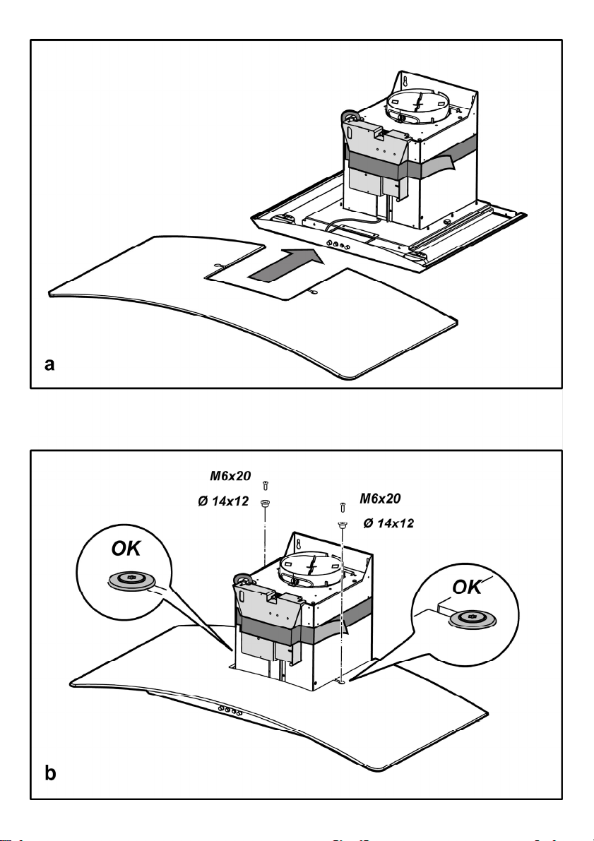
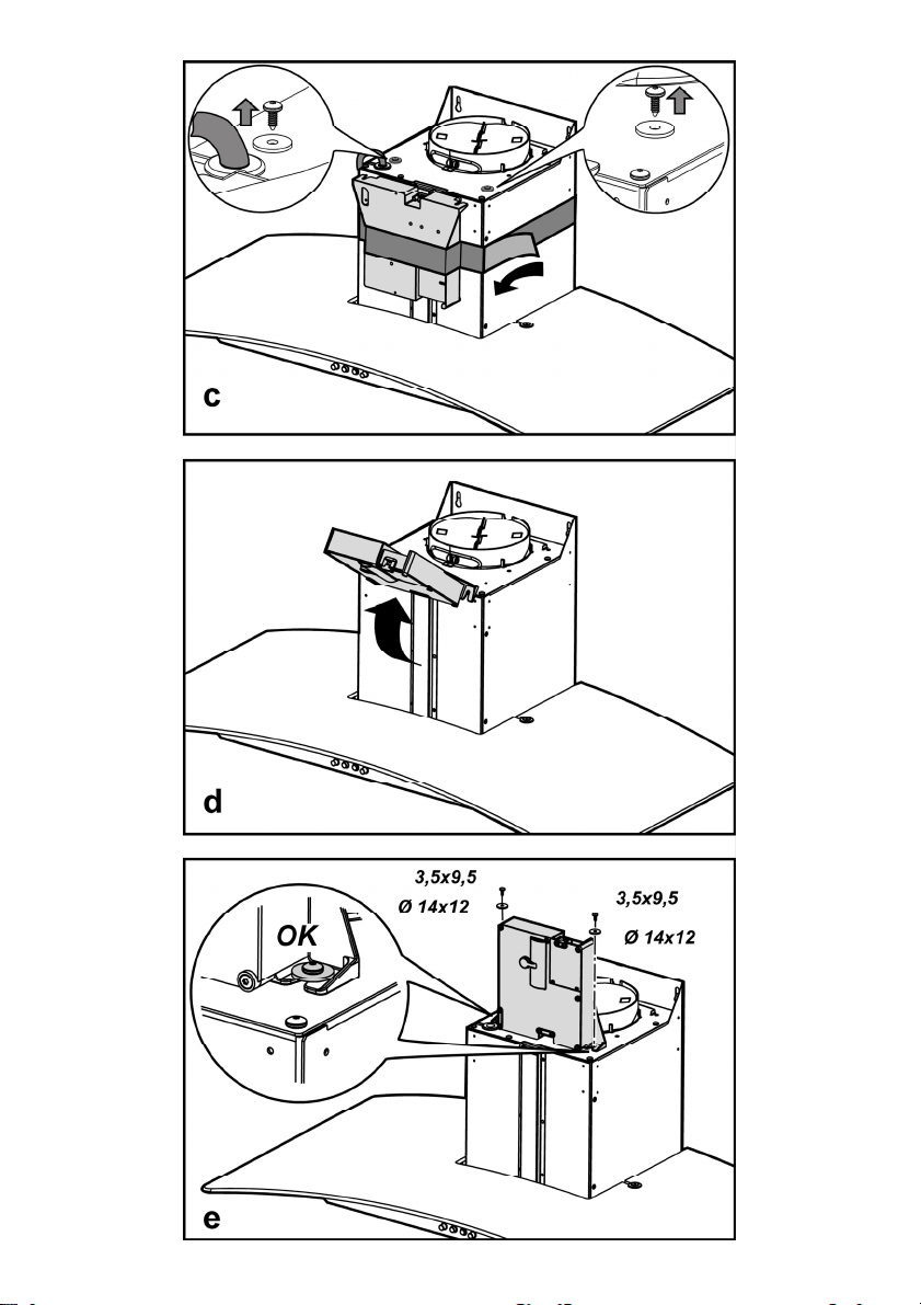
Instalación modelo para pared
Cuando la pantalla vapores es proveida sin montar, debe ser
fijada como en la Fig. a,b.
La caja de conexión eléctrica debe ser fijada como en la Fig.
c,d,e.
Fig. 5
1. Con un lápiz, haga una línea sobre la pared, hasta el techo,
correspondiente a la línea central, facilitará las operaciones
de instalación.
2. Coloque el esquema de perforación sobre la pared: la línea
vertical de medianería impresa en el esquema, tendrá que
corresponder a la línea de medianería dibujada sobre la
pared, además el borde inferior del esquema de perforación
corresponde al borde inferior de la campana.
3. Taladre como indicado en la plantilla, introduzca los tacos de
pared y atornille 2 tornillos en los agujeros superiores,
dejando un espacio entre la cabeza del tornillo y la pared, de
aproximadamente 1cm.
Nota: Haga todos los agujeros indicados en la plantilla: los 2
superiores sirven para enganchar la campana, mientras que
los agujeros inferiores (generalmente 1 central o más
laterales) sirven para la fijación definitiva y de seguridad.
4. Coloque la abrazadera de soporte chimeneas „G“, en la
pared que adhiere en el techo, utilice la abrazadera de
soporte chimeneas como esquema de perforación (si
presente, la pequeña ranura obtenida sobre el soporte, tiene
que coincidir con la línea precedentemente trazada sobre la
pared) y trace con el lápiz 2 agujeros, haga los agujeros,
introduzca los 2 tacos.
5. Fije la abrazadera de soporte chimeneas en la pared con 2
tornillos.
6. Cuelgue la campana en los 2 tornillos superiores (vea fase
de instalación 3).
7. Introduzca y atornille en el/los agujero/s inferiores los tornillos
(y rondana/s) para la fijación definitiva (¡OBLIGATORIO!)
después de verificar el equilibrio de la campana, APRIETE
TODOS LOS TORNILLOS inferiores y superiores.
Nota: los puntos de fijación inferiores son visibles quitando
los filtros de grasa, y se encuentran en los lados y/o en el
centro de la campana (en este último caso después de haber
quitado la armadura del filtro de carbón, si presente).
De cualquier manera, se aconseja usar, cuando disponibles,
los agujeros laterales para aumentar la estabilidad de la
campana.
8. Conecte un tubo (tubo y fajas para la fijación no proveídas,
deben ser compradas) para la descarga de humos al anillo
de conexión arriba de la unidad motor aspirante.
La otra extremidad del tubo tendrá que ser conectada a un
dispositivo de expulsión humos, hacia el exterior en caso de
uso de la campana en versión aspirante. Si se desea usar la
campana en versión filtrante, fije el deflector F en la
abrazadera de fijación chimeneas G, y conecte la otra
extremidad del tubo al anillo de conexión colocado sobre el
deflector F.
9. Conecte a la red eléctrica.
10. Coloque las chimeneas y fíjelas encima de (10a) la
abrazadera de soporte chimeneas, con 2 tornillos „G“
(10b).
11. Haga deslizar la sección inferior de la chimenea, para
cubrir completamente el grupo aspirante, hasta
introducirlo en el lugar apropiado encima de la campana.
Reensamblar el marco del filtro de carbón y el de/ de los
filtro/s anti grasas y controlar el perfecto funcionamiento de la
campana.
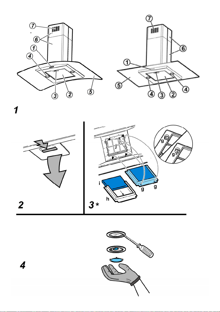
Descripción de la campana
Fig. 1
1. Cuadro de control
2. Filtro antigrasa
3. Manija de desenganche del filtro antigrasa
4. Lámpara halógena
5. Protección contra vapores
6. Chimenea telescópica
7. Salida del aire (sólo para uso en versión filtrante)
Funcionamiento
La campana está dotada de un panel de mandos con control
de las velocidades de aspiración y control de encendido de la
luz para la iluminación del plano de cocción.
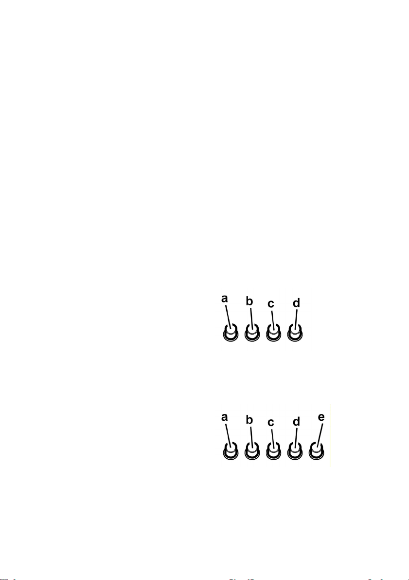
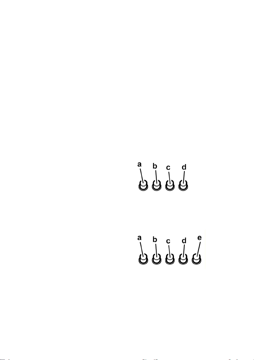
Modelo con panel de mandos con 4 botones
a. Interruptor luz ON/OFF.
b. Interruptor OFF/ velocidad 1
c. Selección velocidad 2
d. Selección velocidad 3
Modelo con botonera con 5 botones
a. Botón ON/OFF luces.
b. Botón OFF aspiración
c. Botón selección potencia de aspiración mínima.
d. Botón selección potencia de aspiración media.
e. Botón selección potencia de aspiración máxima.
8
Page 9

Mantenimiento
¡Atención! Antes de cualquier operación de limpieza o
mantenimiento, retire la campana de la red eléctrica
desconectando el enchufe o desconectando el
interruptor general de la casa.
Limpieza
La campana debe ser limpiada con frecuencia tanto
externamente como internamente (con la misma frecuencia
con la que se realiza el mantenimiento de los filtros de grasa).
Para la limpieza, utilice un paño impregnado de detergente
líquido neutro. No utilice productos que contengan abrasivos.
¡NO UTILICE ALCOHOL!
ATENCION: De no observarse las instrucciones dadas para
limpiar el aparato y sustituir el filtro, puede producirse un
incendio. El fabricante recomienda leerlas y respetarlas
atentamente.
El fabricante no se hace responsable por los daños al motor o
los incendios provocados en el aparato debido a
intervenciones de mantenimiento incorrectas o al
incumplimiento de las normas de seguridad proporcionadas.
Filtro antigrasa
Retiene las partículas de grasa producidas cuando se
cocina.
Para desmontar el filtro antigrasa, tirar de la manija de
desenganche de muelle.
Fig. 2
Filtro al carbón activo (solamente para la versión
filtrante)
Fig. 3
Retiene los olores desagradables producidos por el
cocinado de alimentos.
El filtro al carbón puede lavarse cada dos meses con agua
caliente y detergentes adecuados o en lavavajillas a 65°C (
en caso de lavado con lavavajillas, realice el ciclo de lavado
completo sin platos en el interior.). Quite el agua que haya
quedado en el filtro sin estropearlo, después quite el
almohadillado situado en el interior del armazón de plástico y
póngalo en el horno a 100°C durante diez minutos para
secarlo completamente. Cambie el almohadillado cada 3 años
y cada vez que el paño se estropee.
Saque la cubierta que sujeta el filtro girando 90 grados los
pomos (g) que la sujetan a la campana.
Ponga la placa (i) de carbón en el interior del chasis (h) y
móntelo todo en la correspondiente sede (j).
Es posible utilizar un filtro de carbón tradicional, que no sea
lavable , ni se pueda regenerar, y que se sustituye cada 3-4
meses.
Marco del filtro de carbono y el filtro van juntos ,el conjunto
estructural suministrado con la campana no debe utilizarse.
Para la utilizaciòn de dicho filtro insertar en su hueco y fijar
moviendo en sus mecanismos.
Sustitución de la lámpara
Desconecte el aparato de la red elèctrica.
Atención! Antes de tocar las lámparas asegúrese de que
esten frías.
Sustituir la lámpara dañada con una del mismo tipo como se
especifica en la etiqueta correspondiente o en la
campana cerca de la lámpara misma .
Fig. 4
1. Extraer la protección haciendo palanca con un pequeño
destornillador de boca plana o una herramienta similar.
2. Sustituir la lámpara dañada.
Utilizar sólo lámparas halógenas de 12V -20W max - G4
(Adecuada para su uso en luminaria abierta) prestando
atención en no tocarlas con las manos.
3. Cerrar el plafón (fijación a presión).
Si la iluminación no funciona, antes de llamar al servicio de
asistencia técnica, controlar que las lámparas estén bien
montadas en su sede.
9
Page 10
PT - Instruções para montagem e utilização
Siga especificamente as instruções indicadas neste
manual. Declina-se qualquer responsabilidade por eventuais
inconvenientes, danos ou incêndios provocados ao aparelho,
derivantes da inobservância das instruções indicadas neste
manual. A coifa foi concebida para a aspiração de fumos e
vapores de cozimento e se destina exclusivamente para uso
doméstico.
A coifa pode ter estéticas diferentes a quanto ilustrado
neste livrete, todavia as instruções de uso, manutenção e
instalação permanecem as mesmas.
! É importante conservar este manual para eventuais
consultas futuras.
Em caso de venda ou mudança, certificar-se que o
manual acompanhe o produto.
! Ler cuidadosamente as instruções: elas apresentam
importantes informações sobre a instalação, uso e
segurança.
! Não efetuar variações elétricas ou mecânicas no produto
ou nos tubos de fuga.
! Antes de prosseguir com a instalação do dispositivo,
verificar todos os componentes que não sejam
danificados. Caso contrário, contatar o seu fornecedor e
não prosseguir com a instalação.
Nota: As peças que apresentam o símbolo “(*)” são
acessórios opcionais fornecidos somente em alguns modelos
ou são peças que não acompanham o produto, mas que
precisam ser adquiridas.
Advertências
Atenção! Não conectar o aparelho à rede elétrica enquanto a
instalação não tiver sido totalmente completada.
Antes de qualquer limpeza ou manutenção, desligar a coifa
da rede elétrica tirando o pluge da tomada ou desligando o
interruptor geral da alimentação elétrica.
Para todas as operações de instalação e manutenção, utilize
luvas adequadas para este tipo de atividade.
O aparelho não é destinado para uso de crianças ou pessoas
com alguma incapacidade fisica, motoras, ou mentais
reduzidas, e também à às pessoas sem experiência ou sem
conhecimentos suficientes. Devem ser de ser auxiliadas por
alguém que tenha com conhecimento e capacidade
competência para utilizar o aparelho.
As crianças devem ser controladas de maneira que não
brinquem com o aparelho.
Nunca utilizar a coifa sem a grelha esteja corretamente
montada!
A coifa NUNCA deve ser utilizada como plano de apoio.
Quando a coifa é utilizada ao mesmo tempo com outros
aparelhos a combustão de gás ou outros combustíveis o local
deve dispor de suficiente ventilação.
O ar aspirado não deve ser transportado por meio de ductos
usados para a descarga dos fumos produzidos por aparelhos
a combustão de gás ou de outros combustíveis.
É severamente proibido cozinhar alimentos diretamente na
chama sob a coifa.
O emprego de chama livre é danoso para os filtros e pode dar
lugar a incêndios, portanto, deve ser absolutamente evitado.
A fritura deve ser feita sob controlo de modo a evitar que o
óleo superaquecido se incendeie.
As partes externas podem aquecer-se notávelmente quando
forem usadas com os aparelhos de cocção.
No que diz respeito às medidas técnicas e de segurança a
serem adoptadas para a descarga dos fumos, ater-se
estritamente a quanto previsto pelos regulamentos das
autoridades competentes locais.
A coifa deve ser limpa frequentemente tanto interna quanto
externamente (AO MENOS UMA VEZ POR MÊS, respeitando
as instruções de manutenção indicadas neste manual).
O não atendimento às normas de limpeza da coifa e de
substituição e limpeza dos filtros pode provocar riscos de
incêndio.
A coifa não de ser utilizada sem lâmpadas ou com sua
montagem incorreta, pois isto pode provocar risco de choque
elétrico.
Não nos responsabilizamos por eventuais inconvenientes,
danos ou incêndios provocados ao aparelho, caso as
instruções indicadas neste manual não sejam seguidas
corretamente.
Este aparelho está classificado de acordo com a Diretiva
Europeia 2002/96/EC sobre Resíduos de equipamento
elétrico e eletrónico (REEE).
Ao garantir a eliminação adequada deste produto, estará a
ajudar a evitar potenciais consequências negativas para o
ambiente e para a saúde pública, que poderiam derivar de um
manuseamento de desperdícios inadequado deste produto.
O símbolo
no produto, ou nos documentos que
acompanham o produto, indica que este aparelho não pode
receber um tratamento semelhante ao de um desperdício
doméstico.
Pelo contrário, deverá ser depositado no respectivo centro de
recolha para a reciclagem de equipamento eléctrico e
electrónico.
A eliminação deverá ser efectuada em conformidade com as
normas ambientais locais para a eliminação de desperdícios.
Para obter informações mais detalhadas sobre o tratamento,
a recuperação e a reciclagem deste produto, contate o
Departamento na sua localidade, o seu serviço de eliminação
de desperdícios domésticos ou a loja onde adquiriu o produto.
10
Page 11

Uso
A coifa é fabricada para ser utilizada na versão aspirante,
com exaustão externa do ar, ou filtrante, com recirculação
interna.
Versão aspirante
O exaustor é fornecido com uma saída de ar superior B para
a descarga da fumaça ao exterior ( tubo de descarga e
braçadeiras de fixação não fornecidos). Conectar a coifa ao
tubos e orifícios de descarga de parede com diâmetro
equivalente à saída de ar (flange de união).
O uso de tubos ou orifícios de descarga de parede com
diâmetro inferior pode provocar a diminuição da performance
de aspiração e um drástico aumento do ruído.
Não nos responsabilizamos a este respeito.
Aviso! Se o exaustor já estiver equipado com um filtro de
carvão ativo, terá de ser retirado.
Versão filtrante
Se não for possível descarregar a fumaça e os vapores de
cozimento para o exterior, o exaustor poderá ser utilizado na
versão filtrante, desde que se monte um filtro de carvão
ativo e o deflector F do suporte G. Nesta configuração, a
fumaça e os vapores são reciclados passando pela grade
superior H através de um tubo de descarga ligado à saída
superior de ar B e do anel de conexão montado no deflector F
(o tubo de descarga e as braçadeiras de fixação não são
fornecidos).
Aviso! Se o exaustor não estiver equipado com um filtro
de carvão, terá de ser encomendado e colocado.
Os modelos sem motor de aspiração funcionam
exclusivamente na versão aspirante e devem ser ligados a
uma unidade periférica de aspiração (não fornecida).
As instruções da ligação são fornecidas com a unidade
periférica de aspiração.
Instalação
A distância mínima entre a superfície de suporte dos
recipientes sobre o fogão e a parte mais baixa da coifa não
deve ser inferior a 50cm no caso de fogões elétricos e 65cm
no caso de fogões a gás ou combinados.
Se as instruções de instalação do fogão a gás especificarem
uma distância maior, deve-se levar em conta esta indicação.
Conexão elétrica
A voltagem da rede elétrica deve corresponder à voltagem
indicada na etiqueta das características situada no interior da
coifa. Se dotada de ficha, conectar a coifa a uma tomada em
conformidade com as normas vigentes posta em zona
acessível,mesmo depois da instalação. Se não dotada de
ficha (conexão direta à rede) ou a tomada não se encontra
em zona acessível,mesmo depois da instalação, aplicar um
interruptor bipolar em conformidade com a norma que
assegure a desconexão completa da rede nas condições da
categoria de sobretensão III, conformemente às regras de
instalação.
Atenção! Antes de conectar novamente o circuito da coifa
com a alimentação elétrica, verificar seu funcionamento,
atentar sempre para que o cabo de rede esteja montado
corretamente.
Montagem
Antes de iniciar a instalação:
• Verificar que o produto adquirido tenha dimensões
adequadas para a área escolhida de instalação.
• Tirar o/s filtro/s de carvão ativado (*) se fornecidos (ver
também o parágrafo relativo). Este/s deve/m ser
remontado/s somente caso se deseje utilizar a coifa na
versão filtrante.
• Verificar que dentro da coifa não haja (por motivos de
transporte) materiais extras (por exemplo envelopes com
parafusos (*), garantias (*) etc.), eventualmente tirar e
conservar.
• Se possível desconectar e deslocar a instalação solta ou
fazer correr o vidro abrindo-o de modo a acessar mais
facilmente a parede na parte traseira. Caso contrário,
colocar uma cobertura espessa e protetiva sobre a
bancada e o plano de cozimento para protegê-los contra
danos ou entulho. Selecionar uma superfície plana para
montar a unidade. Cobrir tal superfície com uma
cobertura de proteção e colocar em seu interior todas as
partes da coifa e as ferramentas.
• Além disso, verificar que nas proximidades da área de
instalação da coifa (em área acessível também com a
coifa montada) uma tomada elétrica se encontre a
disposição e seja possível conectar-se a um dispositivo
de descarga fumos para o externo (somente Versão
aspirante).
• Executar todos os trabalhos de alvenaria necessários
(por ex: instalação de uma tomada elétrica e/ou tubo
para a passagem do tubo de descarga).
A coifa é dotada de buchas de fixação adequadas à maior
parte das paredes/tetos.No entanto é necessário que um
técnico qualificado faça sua instalação. A parede/teto deve
ser suficientemente robusta para suportar o peso da coifa.
11
Page 12
Instalação modelo para parede
Quando o anteparo vapores é fornecido desmontado deve ser
fixado como indicado na Fig. a,b.
A caixa de conexão eléctrica deve ser fixada como indicado
na Fig. c,d,e.
Fig. 5
1. Utilizando um lápis, desenhar uma linha na parede até o
tecto, correspondente à linha de centro, isto facilitará as
operações de instalação.
2. Aplicar o gabarito de furação à parede: a linha de centro
vertical impressa no gabarito de furação deverá
corresponder à linha de centro desenhada na parede,
além disso a borda inferior do gabarito de furação
corresponde à borda inferior da coifa.
3. Furar como indicado no gabarito, inserir as buchas e
fixar 2 parafusos nos furos superiores deixando um
espaço entre a cabeça do parafuso e a parede de cerca
de 1cm.
Nota: Executar sempre todos os furos indicados no
gabarito: os 2 superiores servem para enganchar a coifa
enquanto os furos inferiores (geralmente 1 central ou
vários laterais) servem para a fixação definitiva e de
segurança.
4. Aplicar o elemento de suporte chaminés “G” à parede
aderente ao tecto, utilizar o elemento de suporte
chaminés como gabarito de furação (se presente, o
pequeno rasgo no suporte deve coincidir com a linha
anteriormente traçada na parede) e marcar a lápis 2
furos, executar os furos, inserir 2 buchas.
5. Fixar o elemento de suporte chaminés à parede com 2
parafusos.
6. Pendurar a coifa aos 2 parafusos superiores (ver fase de
instalação 3).
7. Introduzir e roscar no/s furo/s inferior/es os parafusos (e
anilha/s) para a fixação definitiva (OBRIGATÓRIO!) em
seguida, após ter verificado a disposição da coifa,
APERTAR TODOS OS PARAFUSOS inferiores e
superiores.
Nota: os pontos de fixação inferiores são visíveis tirando
o filtro gorduras e se encontram nos lados e no centro da
coifa (neste último caso após ter tirado o chassis do filtro
de carvão activado se presente).
Em todo caso aconselha-se utilizar, quando disponíveis,
os furos laterais para aumentar a estabilidade da coifa.
8. Efectuar a conexão a um tubo (tubo e abraçadeiras para
a fixação não fornecidos, a serem adquiridos) para a
descarga dos fumos ao anel de conexão posto sobre a
unidade motor aspirante.
Em caso de uso da coifa na versão aspirante a outra
extremidade do tubo deverá ser conectada a um
dispositivo de expulsão fumos para o externo. Caso se
deseje utilizar a coifa na versão filtrante, fixar o deflector
F ao elemento de suporte chaminés G e conectar a outra
extremidade do tubo ao anel de conexão posto no
deflector F.
9. Executar a conexão eléctrica.
10. Aplicar as chaminés e fixá-las em cima com 2 parafusos
(10a) ao elemento de suporte chaminés “G“ (10b).
11. Deixar a secção inferior da chaminé escorregar como
cobertura completa do conjunto aspirante até inseri-la na
respectiva sede sobre a coifa.
Remontar o chassis do filtro de carvão activado e o/s filtro/s
gorduras e controlar o perfeito funcionamento da coifa.
Descrição do exaustor
Fig. 1
1. Painel de controle
2. Filtro antigordura
3. Puxador para libertar o filtro antigordura
4. Lâmpada de halogéneos
5. Proteção contra os vapores
6. Chaminé telescópica
7. Saída do ar (só para a utilização na versão filtrante)
Funcionamento
O exaustor é dotado de um painel de comandos com um
controlo de velocidade de aspiração e um controlo para
acender a luz de iluminação do plano de cozedura.
Modelo com botoeira com 4 teclas
a. Interruptor luz ON/OFF.
b. Interruptor OFF/velocidade 1
c. Selecção velocidade 2
d. Selecção velocidade 3
Modelo com botoeira com 5 teclas
a. botão ON/OFF luzes
b. botão OFF aspiração
c. botão de seleção da potência de aspiração mínima
d. botão de seleção da potência de aspiração média
e. botão de seleção da potência de aspiração máxima
12
Page 13

Manutenção
Atenção! Antes de qualquer operação de limpeza ou
manutenção, desconectar a coifa da rede elétrica tirando
o pluge da tomada ou desligando o interruptor geral da
alimentação elétrica.
Limpeza
O exaustor deve ser limpo frequentemente, interna e
externamente (pelo menos com a mesma frequência com a
qual se efectua a manutenção dos filtros antigorduras).
Para a limpeza use um pano umedecido com detergentes
líquidos neutros. Evite o uso de produtos contendo abrasivos.
NÃO UTILIZE ÁLCOOL!
Atenção: O não cumprimento das instruções fornecidas para
a limpeza do aparelho e para a limpeza ou substituição do
filtro pode provocar riscos de incêndio.
O fabricante não se responsabiliza por danos causados ao
motor ou decorrentes de incêndio, provocados por uma
manutenção inadequada ou pelo não cumprimento das
indicações de segurança citadas neste manual.
Filtro antigordura
Capta as partículas de gordura derivantes do cozimento.
Para desmontar o filtro anti gordura puxe o puxador de
libertação com mola.
Fig. 2
Filtro de carvão activo (só para a versão filtrante)
Fig. 3
Retém os odores desagradáveis produzidos durante a
preparação de alimentos.
O filtro de carvão pode ser lavado de dois em dois meses em
água quente e detergentes adequados ou em máquina de
lavar louça a 65 °C (para a lavagem em máquina, utilize o
ciclo completo sem colocar outra loiça na máquina).
Tire a água em excesso tomando cuidado para não estragar o
filtro. Em seguida, tire o pano posto no interior da estrutura de
plástico e deixe-o secar definitivamente no forno durante 10
minutos a 100 °C.
Substitua o pano a cada 3 anos e sempre que notar sinais de
danos no tecido.
Remover o chassis de suporte do filtro girando as manoplas
(g) que o fixam à coifa de 90°.
Coloque o pano (i) de carvão no interior da estrutura (h) e
reinstale o conjunto na sede correspondente (j).
É possível utilizar um filtro de carvão activado de tipo
tradicional, não lavável nem regenerável, a ser substituído
cada 3-4 meses.
Chassis e elemento do filtro de carvão activado são soldados
juntos, portanto, o eventual chassis fornecido com a coifa não
deve ser utilizado.
Para o uso inserir em sua sede e fixar agindo nos dispositivos
específicos.
Substituição das lâmpadas
Desligar o aparelho da rede elétrica;
Atenção! Antes de tocar as lâmpadas, certificar-se que
estejam frias.
Substituir a lâmpada queimada com outra do mesmo tipo,
conforme especificado na etiqueta de caracteristicas ou perto
da própria lâmpada no exaustor.
Fig. 4
1. Extraia a proteção usando uma pequena chave de
parafuso ou ferramenta semelhante como alavanca.
2. Substitua a lâmpada queimada.
Utilize exclusivamente lâmpadas de halogéneo de 12V -
20W max - G4, tomar cuidado para não as tocar com as
mãos.
3. Feche a cobertura (fixação por encaixe).
Se a iluminação não funcionar, verifique se as lâmpadas
foram instaladas corretamente no seu devido lugar antes de
chamar a assistência técnica.
13
Page 14

DE - Montage- und Gebrauchsanweisung
Die Instruktionen, die in diesem Handbuch gegeben
werden, müssen strikt eingehalten werden. Es wird keinerlei
Haftung übernommen für mögliche Mängel, Schäden oder
Brände der Dunstabzugshaube, die auf die Nichtbeachtung der
Vorschriften in diesem Handbuch zurückzuführen sind. Die
Dunstabzugshaube ist fuer die Absaugung der Kochduenste
und Verbrennungsgase, die waehrend des Kochvorgangs
entstehen , entwickelt. Sie ist nur zum Hausgebrauch geeignet.
Der Dunstabzugshaube kann von der aesthetischen Seite
her ander sein als die Zeichnungen die in diesem
Bedienungsanleitung geschrieben sind.
Die Bedienungsanleitungen , die Wartung und die
Installation sind aber gleich.
! Es ist wichtig diese Bedienungsanleitung zu behalten um
sie in jedem Moment nachzuschlagen. Im Fall von
Verkaufen, Abtretung oder Umziehen, versichern Sie sich
bitte dass Sie mit dem Produkt zusammen bleibt.
! Die Bedienungsanleitungen richtig lesen: es gibt wichtige
Informationen ueber die Installation, Benutzen und
Sicherheit.
! Führen Sie keine elektrische oder mechanische
Aenderungen am Produkt oder an den Abgasrohren vor.
! Vor der Installation vergewissern Sie sich, dass das Gerät
keine Transportschäden aufweist. Bei auftretenden
Problemen setzen Sie sich bitte mit Ihrem Händler in
Verbindung.
Hinweis: Die mit dem (*) gekennzeichneten Teile sind
Zubehörteile, die nur bei einigen Modellen im Lieferumfang
enthalten sind oder Teile, die nicht im Lieferumfang enthalten
sind, und somit extra erworben werden müssen.
Warnung
Achtung! Das Gerät nicht an das Stromnetz anschließen,
solange die Installation noch nicht abgeschlossen ist.
Vor Beginn sämtlicher Reinigungs- oder Wartungsarbeiten muss
das Gerät durch Ziehen des Steckers oder Betätigen des
Hauptschalters der Wohnung vom Stromnetz getrennt werden.
Bei allen Installations- und Instandhaltungsarbeiten immer
Schutzhandschuhe tragen.
Kinder nicht mit dem Gerät spielen lassen.
Erwachsene und Kinder dürfen nie unbeaufsichtigt das Gerät
betreiben,
– wenn sie körperlich oder geistig dazu nicht in der Lage sind,
– oder wenn ihnen Wissen und Erfahrung fehlen, das Gerät
richtig und sicher zu bedienen.
Die Dunstabzugshaube niemals ohne korrekt montiertes Gitter
in Betrieb setzen!
Die Dunstabzugshaube darf NIEMALS als Abstellfläche
verwendet werden, sofern dies nicht ausdrücklich angegeben
wird.
Der Raum muss über eine hinreichende Belüftung verfügen,
wenn die Dunstabzugshaube mit anderen gas- oder
brennstoffbetriebenen Geräten gleichzeitig verwendet wird.
Bei gleichzeitigem Betrieb der Dunstabzugshaube im
Abluftbetrieb und Feuerstätten darf im Aufstellraum der
Feuerstätte der Unterdruck nicht größer als 4 Pa (4 x 10
-5
bar)
sein. Die angesaugte Luft darf nicht in Rohre geleitet werden,
die für die Ableitung der Abgase von gas- oder
brennstoffbetriebenen Geräten genutzt werden.
Es ist strengstens verboten, unter der Haube mit offener
Flamme zu kochen.
Eine offene Flamme beschädigt die Filter und kann Brände
verursachen, daher ist dies in jedem Fall zu vermeiden.
Das Frittieren muss unter Aufsicht erfolgen, um zu vermeiden,
dass das überhitzte Öl Feuer fängt.
Zugängliche Teile können beim Gebrauch mit Kochgeräten
heiss werden.
In Bezug auf technische und Sicherheitsmaßnahmen für die
Ableitung der Abluft sind die Vorschriften der zuständigen
örtlichen Behörden strengstens einzuhalten.
Die Haube muss regelmäßig innen und außen gereinigt werden
(MINDESTENS EINMAL IM MONAT, diesbezüglich sind in
jedem Fall die ausdrücklichen Angaben in der
Wartungsanleitung dieses Handbuchs zu beachten).
Eine Nichtbeachtung der Vorschriften zur Reinigung der Haube
sowie zur Auswechselung und Reinigung der Filter führt zu
Brandgefahr.
Um das Risiko eines Stromschlages zu vermeiden, darf die
Dunstabzugshaube ohne richtig eingesetzte Lampen nicht
betrieben werden.
Es wird keinerlei Haftung übernommen für Fehler, Schäden oder
Brände des Gerätes, die durch Nichteinhaltung der in diesem
Handbuch aufgeführten Anweisungen verschuldet wurden.
In Übereinstimmung mit den Anforderungen der Europäischen
Richtlinie 2002/96/EG über Elektro- und Elektronik-Altgeräte
(WEEE) ist vorliegendes Gerät mit einer Kennzeichnung
versehen.
Sie leisten einen positiven Beitrag für den Schutz der Umwelt
und die Gesundheit des Menschen, wenn Sie dieses Gerät
einer gesonderten Abfallsammlung zuführen. Im unsortierten
Siedlungsmüll könnte ein solches Gerät durch unsachgemäße
Entsorgung negative Konsequenzen nach sich ziehen.
Auf dem Produkt oder der beiliegenden Produktdokumentation
ist folgendes Symbol
einer durchgestrichenen
Abfalltonne abgebildet. Es weist darauf hin, dass eine
Entsorgung im normalen Haushaltsabfall nicht zulässig ist.
Entsorgen Sie dieses Produkt im Recyclinghof mit einer
getrennten Sammlung für Elektro- und Elektronikgeräte. Die
Entsorgung muss gemäß den örtlichen Bestimmungen zur
Abfallbeseitigung erfolgen.
Bitte wenden Sie sich an die zuständigen Behörden Ihrer
Gemeindeverwaltung, an den lokalen Recyclinghof für
Haushaltsmüll oder an den Händler, bei dem Sie dieses Gerät
erworben haben, um weitere Informationen über Behandlung,
Verwertung und Wiederverwendung dieses Produkts zu
erhalten.
14
Page 15

Betriebsart
Die Haube kann sowohl als Abluftgërat als auch als
Umluftgërat eingesetzt werden.
Abluftbetrieb
Die Haube verfügt über einen oberen Luftaustritt B zum
Ableiten der Küchengerüche nach außen (Abluftrohr und
Rohrschellen werden nicht geliefert). Die Dunstabzugshaube
an Abluftrohre und Wandabluftauslass mit dem selben
Durchmesser wie der Luftausgang verbinden
(Anschlussflansch).
Die Benutzung von Rohren und Wandabluftauslass mit
geringerem Durchmesser, verursacht eine Verringerung der
Abluftleistung und eine drastische Zunahme der
Geraeuschentwicklung.
Jegliche Verantwortung diesbezueglich wird daher abgelenkt
Achtung! Sollte die Dunstabzugshaube mit einem
Aktivkohlefilter versehen sein, so muß dieser entfernt
werden.
Umluftbetrieb
Ist eine Ableitung von Rauch und Kochdämpfen ins Freie nicht
möglich, kann die Haube mit Umluftbetrieb arbeiten; in
diesem Fall muß ein Aktivkohlefilter bzw. ein Umleitgitter F an
der Halterung (Bügel) G montiert werden; auf diese Weise
wird die Luft durch das obere Gitter H mit Hilfe eines
Abluftrohres, das an den oberen Luftaustritt B angeschlossen
ist, und eines Anschlussrings am Umleitgitter F (Abluftrohr
und Rohrschellen sind nicht im Lieferumfang enthalten)
rückgeführt.
Achtung! Sollte die Dunstabzugshaube nicht mit einem
Aktivkohlefilter versehen sein, ist dieser zu bestellen und
vor Inbetriebnahme des Gerätes einzusetzen.
Modelle ohne Saugmotor funktionieren nur mit Abluftbetrieb
und müssen an eine externe Saugeinheit (nicht im
Lieferumfang enthalten) angeschlossen werden.
Die Anschlussanleitungen liegen der externe Saugeinheit bei.
Befestigung
Der Abstand zwischen der Abstellfläche auf dem Kochfeld und
der Unterseite der Dunstabzugshaube darf 50cm im Fall von
elektrischen Kochfeldern und 65cm im Fall von Gas- oder
kombinierten Herden nicht unterschreiten.
Wenn die Installationsanweisungen des Gaskochgeräts einen
größeren Abstand vorgeben, ist dieser zu berücksichtigen.
Elektrischer Anschluss
Die Netzspannung muss der Spannung entsprechen, die auf
dem Betriebsdatenschild im Innern der Haube angegeben ist.
Sofern die Haube einen Netzstecker hat, ist dieser an
zugänglicher Stelle an eine den geltenden Vorschriften
entsprechende Steckdose auch nach der Montage
anzuschließen. Bei einer Haube ohne Stecker (direkter
Netzanschluss) oder falls der Stecker nicht zugänglich ist, ist ein
normgerechter zweipoliger Schalter auch nach der Montage
anzubringen, der unter Umständen der Überspannung
Kategorie III entsprechend den Installationsregeln ein
vollständiges Trennen vom Netz garantiert.
Hinweis! Vor der Inbetriebnahme muss sichergestellt sein ,
dass die Netzversorgungleitung (Steckdose) ordnungsgemäß
montiert wurde.
Montage
Bevor Sie mit der Montage beginnen:
• Überprüfen Sie, dass das erstandene Produkt von der
Größe her dem Bereich entspricht, in dem es angebracht
werden soll.
• Entfernen Sie den/die Aktivkohlefilter (*), falls vorhanden
(siehe hierzu auch den entsprechenden Absatz "Wartung").
Der/die Aktivkohlefilter wird/werden nur wieder in die
Dunstabzugshaube eingesetzt, wenn diese im
Umluftbetrieb verwendet werden soll.
• Vergewissern Sie sich, dass sich im Inneren der
Dunstabzugshaube (aus Transportgründen) kein im
Lieferumfang enthaltenes Material (zum Beispiel Tütchen
mit Schrauben (*), die Garantie (*), usw.) befindet; falls
vorhanden, entfernen Sie dieses und heben Sie sie auf.
• Falls möglich, entfernen Sie die Möbel unter und um die
Dunstabzugshaube herum, um besseren Zugriff auf die
hintere Wand/Decke zu haben, wo die Haube angebracht
wird. Sonst legen Sie bitte eine Schutzabdeckung auf die
Kochplatte, Arbeitsfläche, sowie die Möbel und Wände, um
sie vor Schäden oder Schmutz zu schützen. Wählen Sie
eine ebene Oberfläche, um die Einheit zusammenzubauen.
Decken Sie diese Oberfläche mit einer Schutzfolie ab und
legen Sie die Dunstabzugshaube sowie alle im
Lieferumfang enthaltenen Teile darauf.
• Vergewissern Sie sich zudem, dass in der Nähe der
Fläche, an der die Dunstabzugshaube angebracht werden
soll (eine Fläche, die auch nach der Montage der
Dunstabzugshaube weiter zugänglich sein muss), eine
Steckdose vorhanden ist und es möglich ist, die
Dunstabzugshaube an eine Vorrichtung zum Ableiten der
Dämpfe ins Freie anzuschließen (nur Abluftbetrieb).
• Führen Sie alle notwendigen Arbeiten durch (z.B.: Einbau
einer Steckdose und/oder Anbringen eines Loches für den
Durchgang des Abluftrohres).
Die Abzugshaube ist mit Dübeln ausgestattet, die für die
meisten Wände/Decken geeignet sind. Trotzdem sollte ein
qualifizierter Techniker hinzugezogen werden, der entscheidet,
ob die Materialien für die jeweilige Wand/Decke geeignet sind.
Außerdem muß die Wand/Decke das Gewicht der Abzugshaube
tragen muss.
15
Page 16

Installation des Modells für die Wand
Wenn das Dunstbild ausmontiert mitgeliefert wird, muss man es ,
wie im Bild a.b.gezeigt, befestigen.Die elektrische
Verbindungsschachtel muss man, wie in Bild c,d,e.gezeigt,
befestigen.
Bild 5
1. Mit einem Bleistift, eine Streife an die Wand zeichnen , bis zur
Decke, entsprechend der Mittellinie, das wird die
Installationsoperationen erleichtern.
2. Das Bohrenscheema an die Mauer daraufmachen: die
senkrechte, auf das Bohrenscheema gedruckten Mittellinie
muss der auf die Mauer gezeichnten Mittellinie entsprechen,
die untere Seite des Bohrenscheema entspricht der unteren
Seite der Dunstabzugshaube.
3. Wie auf der Radienschablone geschrieben , die Oese
hereintun und zwei Schrauben in die oberen Loecher, Platz
zwischen dem Kopf der Schraube und der Mauer zon zirka
ein Centimeter lassen.
Hinweis: alle die auf der Radienschablonen geschriebenen
Loecher immer erfuellen : die zwei obere sind dafuer
nuetzlich um den Dunstabzugshaube zu haengen waehrend
die untere Loecher (im allgemeinen eins im Zentrum oder
mehrere auf der Seite) sind dafuer nuetzlich um eine
endgueltige Befestigung und Sicherheit zu haben.
4. Den Kaminhaltersteigbuegel „G“ an die an der Decke
haftende Wand alla daraufmachen, den
Kaminhaltersteigbuegel benutzen, den
Kaminhaltersteigbuegel als Loecherscheema (wenn
anwesend, die kleine Oese die aus dem Halter gezogen
worden ist, sie muss mit der, vorher an die Wand
gezeichnete Linee abstimmen) benutzen und sie muessen
mit dem Bleistift zwei Loecher zeichnen ,die Loecher
machen, die zwei Einsatzstueck hereinfuegen.
5. Den Kaminhaltersteigbuegel an die Wand mit zwei
Schrauben befestigen
6. Die Dunstabzugshaube an die zwei oberen Schrauben
haengen (bitte die Installationphase 3 anschauen).
7. Die Schrauben (und die Unterlegscheibe )Unterlegscheiben!)
hereinfuegen und sie ins Loch oder in die Loecher befestigen
um eine endgueltige Befestigung zu machen (PFLICHT!!)
nach diesem, nachdem sie die Einrichtung der
Dunstabzugshaube nachgeprueft haben, ALLE DIE
SCHRAUBEN BEFESTIGEN , weder die untere noch die
obere.
Hinweis: die untere Befestigungspunkte sind sichtbar wenn
man die Fettfilter wegmacht und sie sind and den Seiten oder
in der Mitte der Dunstabzugshaube posizioniert (in diesem
laetztem Fall , nachdem man das Filtergeruest aus der Kohle
weggemacht hat , sollte es dabei sein).
Auf jedem Fall, wird es empfohlen die seitlichen Loecher,
wenn sie zur Verfuegung sind , zu benutzen um die
Stabilitaet der Dunstabzugshaube zu steigern.
8. Einen Schauch verbinden (Schauch und Streifbaender fuer
die Befestigung die nicht mitgeliefert sind, sonder man muss
sie selber kaufen) fuer das Entladen der Rauchen an den
Verbindungsring der auf der Abzugsmotoreinheit positioniert
ist .
Das andere Ende des Schlauchs muss an eine
Rauchauswerfvorrichtung verbunden werden in Richtung
nach aussen wenn man die Dunstabzugshabe in Abzug
Version benutzt. Wenn man die Dunstabzugshaube in
Filterversion benutzen moechte, man muss an dem
Kaminhaltersteigbuegel G, den Deflektor F befestigen und
das andere Ende des Schlauchs and den auf den Deflektor F
positionierten Verbindungsring befestigen.
9. Die elektrische Verbindung erfuellen.
10. Die Kaminen darauftun und sie mit zwei Schrauben (10a ) an
den Kaminhaltersteigbuegel darauf „G“ (10b) befestigen .
11. Den unteren Teil des Kamins ruetchen lassen damit die
Abzuggruppe ganz bedeckt wird bis diese Abzugsgruppe
in den richtigen Platz auf der Dunstabzugshaube
eingefuegt wird. Das Kohlefiltergestell und den/die
Fettfilter wieder einbauen und den ordnungsgemäßen
Betrieb der Haube prüfen.
Beschreibung der Dunstabzugshaube
Bild 1
1. Bedienfeld
2. Fettfilter
3. Griff zum Aushaken des Fettfilters
4. Halogenlampe
5. Dunstschirm
6. Teleskopkamin
7. Luftaustritt (nur bei Umluftbetrieb)
Betrieb
Die Dunstabzugshaube ist mit einer Bedienungsblende
ausgestattet, die mit einer Steuerung für die Ansaugstärke
bzw. -geschwindigkeit, sowie einer Steuerung zur Einstellung
der Arbeitsplatzbeleuchtung versehen ist.
Modell mit 4-Tasten-Bedienfeld
a. Lichtschalter ON/OFF.
b. Schalter OFF/Geschwindlichkeit 1.
c. Geschwindlichkeitauswahl 2 .
d. Geschwindlichkeitauswahl 3 .
Modelle mit der Druckknopftafel mit 5 Tasten.
a. Schalter ON/OFF Beleuchtung
b. Schalter OFF der Absaugfunktion
c. Schalter zum Einschalten der geringsten Saugstärke
d. Schalter zum Einschalten der mittleren Saugstärke
e. Schalter zum Einschalten der maximalen Saugstärke
16
Page 17

Wartung
Hinweis ! Vor jeder Reinigung und Pflege ist die
Dunstabzugshaube durch Ziehen des Netzsteckers oder
Ausschalten der Sicherung stromlos zu machen.
Reinigung
Die Dunstabzugshaube muss sowohl innen als auch außen
häufig gereinigt werden (etwa in denselben Intervallen, wie die
Wartung der Fettfilter). Zur Reinigung ein mit flüssigem
Neutralreiniger getränktes Tuch verwenden. Keine Produkte
verwenden, die Scheuermittel enthalten.
KEINEN ALKOHOL VERWENDEN!
Achtung: Nichtbeachtung dieser Anweisungen zur Reinigung
des Gerätes und zum Wechsel bzw. zur Reinigung der Filter
kann zum Brand führen. Diese Anweisungen sind unbedingt
zu beachten!
Der Hersteller übernimmt keine Haftung für irgendwelche
Schäden am Motor oder Brandschäden, die auf eine
unsachgemäße Wartung oder Nichteinhaltung der oben
angeführten Sicherheitsvorschriften zurückzuführen sind.
Fettfilter
Diese dienen dazu, die Fettpartikel, die beim Kochen frei
werden, zu binden.
Zwecks Demontage der Fettfilter den Aushakgriff ziehen.
Bild 2
Aktivkohlefilter (nur bei der Umluftversion)
Bild 3
Dieser Filter bindet die unangenehmen Gerüche, die beim
Kochen entstehen.
Der Aktivkohlefilter wird alle zwei Monate in warmem Wasser
und geeigneten Waschmitteln oder in der Spülmaschine bei
65°C gewaschen (in diesem Fall den ollständigen Spülzyklus
– ohne zusätzliches Geschirr im Inneren der
Geschirrspülmaschine - einschalten).
Das überschüssige Wasser entfernen, ohne dabei den Filter
zu beschädigen; danach das Vlies aus dem Plastikrahmen
entfernen und dieses bei 100° für 10 Minuten in den Ofen
legen, um es vollständig zu trocknen. Das Vlies muss alle 3
Jahre ausgewechselt werden und weiterhin jedes Mal dann,
wenn es beschädigt ist.
Das Gestell, das den Filter trägt, abnehmen, dafür die Knäufe
(g), die es an der Haube befestigen, um 90° drehen. Das
Kohlekissen (i) in den Rahmen (h) schieben und alles wieder
an entsprechender Stelle (j) montieren.
Es besteht die Möglichkeit einen traditionellen Kohlefilter zu
benutzen, welcher weder gewaschen noch regeneriert werden
kann. Dieser Kohlefilter muss alle 3 bis 4 Monate gewechselt
werden.
Das Kohlefiltergestell und der Filter sind
zusammengeschweißt, das eventuell mit der Haube
mitgelieferte Gestell ist daher nicht zu verwenden.
Der Kohlefilter wird in die Dunstabzugshaube eingesetzt und
mit den vorgesehenen 2 Plastikschrauben befestigt.
Ersetzen der Lampen
Das Gerät vom Stromnetz nehmen.
Hinweis: Vor Berühren der Lampen sich vergewissern, dass
sie abgekühlt sind.
Ersetzen Sie die defekte lampe durch eine neue des gleichen
Typs und gleicher Leistung, wie im Typenschild angegeben
Bild 4
1. Die Lampenabdeckung mit Hilfe eines kleinen
Schlitzschraubenziehers oder ähnlichem entfernen.
2. Die defekte Lampe auswechseln.
Ausschließlich Halogenlampen zu m12V -20W max - G4
verwenden und darauf achten, diese nicht mit den Händen
zu berühren.
3. Die Lampenabdeckung wieder schließen
(Schnappverschluss).
Sollte die Beleuchtung nicht funktionieren, erst kontrollieren,
ob die Lampen einwandfrei eingesetzt sind, bevor man sich
an den Kundendienst wendet.
17
Page 18

EN - Instruction on mounting and use
Closely follow the instructions set out in this manual. All
responsibility, for any eventual inconveniences, damages or
fires caused by not complying with the instructions in this
manual, is declined. The hood is conceived for the suction of
cooking fumes and steam and is destined only for domestic
use.
The hood can look different to that illustrated in the
drawings in this booklet. The instructions for use,
maintenance and installation, however, remain the same.
! It is important to conserve this booklet for consultation at
any moment. In the case of sale, cession or move, make
sure it is together with the product.
! Read the instructions carefully: there is important
information about installation, use and safety.
! Do not carry out electrical or mechanical variations on the
product or on the discharge conduits.
! Before proceeding with the installation of the appliance
verify that there are no damaged all components.
Otherwise contact your dealer and do not proceed with
the installation.
Note: the elements marked with the symbol “(*)” are optional
accessories supplied only with some models or elements to
purchase, not supplied.
Caution
WARNING! Do not connect the appliance to the mains until
the installation is fully complete.
Before any cleaning or maintenance operation, disconnect
hood from the mains by removing the plug or disconnecting
the mains electrical supply.
Always wear work gloves for all installation and maintenance
operations.
The appliance is not intended for use by children or persons
with impaired physical, sensorial or mental faculties, or if
lacking in experience or knowledge, unless they are under
supervision or have been trained in the use of the appliance
by a person responsible for their safety.
This appliance is designed to be operated by adults, children
should be monitored to ensure that they do not play with the
appliance.
This appliance is designed to be operated by adults. Children
should not be allowed to tamper with the controls or play with
the appliance.
Never use the hood without effectively mounted grating!
The hood must NEVER be used as a support surface unless
specifically indicated.
The premises where the appliance is installed must be
sufficiently ventilated, when the kitchen hood is used together
with other gas combustion devices or other fuels.
The ducting system for this appliance must not be connected
to any existing ventilation system which is being used for any
other purpose such as discharging exhaust fumes from
appliances burning gas or other fuels.
The flaming of foods beneath the hood itself is severely
prohibited.
The use of exposed flames is detrimental to the filters and
may cause a fire risk, and must therefore be avoided in all
circumstances.
Any frying must be done with care in order to make sure that
the oil does not overheat and ignite.
Accessible parts of the hood may became hot when used with
cooking appliance.
With regards to the technical and safety measures to be
adopted for fume discharging it is important to closely follow
the regulations provided by the local authorities.
The hood must be regularly cleaned on both the inside and
outside (AT LEAST ONCE A MONTH).
This must be completed in accordance with the maintenance
instructions provided in this manual). Failure to follow the
instructions provided in this user guide regarding the cleaning
of the hood and filters will lead to the risk of fires.
Do not use or leave the hood without the lamp correctly
mounted due to the possible risk of electric shocks.
We will not accept any responsibility for any faults, damage or
fires caused to the appliance as a result of the nonobservance of the instructions included in this manual.
This appliance is marked according to the European directive
2002/96/EC on Waste Electrical and Electronic Equipment
(WEEE). By ensuring this product is disposed of correctly, you
will help prevent potential negative consequences for the
environment and human health, which could otherwise be
caused by inappropriate waste handling of this product.
The symbol
on the product, or on the documents
accompanying the product, indicates that this appliance may
not be treated as household waste. Instead it should be taken
to the appropriate collection point for the recycling of electrical
and electronic equipment. Disposal must be carried out in
accordance with local environmental regulations for waste
disposal.
For further detailed information regarding the process,
collection and recycling of this product, please contact the
appropriate department of your local authorities or the local
department for household waste or the shop where you
purchased this product.
18
Page 19

Use
The hood is designed to be used either for exhausting or filter
version.
Ducting version
The hood is equipped with a top air outlet B for discharge of
fumes to the outside (exhaust pipe and pipe fixing clamps not
provided). Connect the hood and discharge holes on the walls
with a diameter equivalent to the air outlet (connection flange).
Using the tubes and discharge holes on walls with smaller
dimensions will cause a diminution of the suction performance
and a drastic increase in noise.
Any responsibility in the matter is therefore declined.
Attention! If the hood is supplied with carbon filter, then it
must be removed.
Filter version
Should it not be possible to discharge cooking fumes and
vapour to the outside, the hood can be used in the filter
version, fitting an activated carbon filter and the deflector F
on the support (bracket) G, fumes and vapours are recycled
through the top grille H by means of an exhaust pipe
connected to the top air outlet B and the connection ring
mounted on the deflector F (exhaust pipe and pipe fixing
clamps not provided).
Attention! If the hood is not supplied with carbon filter,
then it must be ordered and mounted.
The models with no suction motor only operate in ducting
mode, and must be connected to an external suction device
(not supplied).
The connecting instructions are supplied with the peripheral
suction unit.
Installation
The minimum distance between the supporting surface for the
cooking equipment on the hob and the lowest part of the
range hood must be not less than 50cm from electric cookers
and 65cm from gas or mixed cookers.
If the instructions for installation for the gas hob specify a
greater distance, this must be adhered to.
Electrical connection
The mains power supply must correspond to the rating
indicated on the plate situated inside the hood. If provided with
a plug connect the hood to a socket in compliance with current
regulations and positioned in an accessible area, after
installation. If it not fitted with a plug (direct mains connection)
or if the plug is not located in an accessible area, after
installation, apply a double pole switch in accordance with
standards which assures the complete disconnection of the
mains under conditions relating to over-current category III, in
accordance with installation instructions.
Warning! Before re-connecting the hood circuit to the mains
supply and checking the efficient function, always check that
the mains cable is correctly assembled.
Mounting
Before beginning installation:
• Check that the product purchased is of a suitable size for
the chosen installation area.
• Remove the charcoal (*) filter/s if supplied (see also
relative paragraph). This/these is/are to be mounted only
if you want lo use the hood in the filtering version.
• Check (for transport reasons) that there is no other
supplied material inside the hood (e.g. packets with
screws (*), guarantees (*), etc.), eventually removing
them and keeping them.
• If possible, disconnect and move freestanding or slide-in
range from cabinet opening to provide easier access to
rear wall/ceiling. Otherwise put a thick, protective
covering over countertop, cooktop or range to protect
from damage and debris. Select a flat surface for
assembling the unit. Cover that surface with a protective
covering and place all canopy hood parts and hardware
in it.
• In addition check whether near the installation area of the
hood (in the area accessible also with the hood mounted)
an electric socket is available and it is possible to
connect a fumes discharge device to the outside (only
suction version).
• Carry out all the masonry work necessary (e.g.
installation of an electric socket and/or a hole for the
passage of the discharge tube).
Expansion wall plugs are provided to secure the hood to most
types of walls/ceilings. However, a qualified technician must
verify suitability of the materials in accordance with the type of
wall/ceiling. The wall/ceiling must be strong enough to take
the weight of the hood. Do not tile, grout or silicone this
appliance to the wall. Surface mounting only.
19
Page 20

Installation wall model
When the vapour catcher is disassembled, it must be fixed as
shown in Fig. a,b.
The electric connection box must be assembled as shown in
Fig. c,d,e.
Fig. 5
1. Drawing a line on the wall with a pencil up to the ceiling,
corresponding to the centre line, will make the installation
operations easier.
2. Apply the perforation diagram to the wall: the vertical
centre line printed on the perforation diagram should
correspond to the centre line drawn on the wall. In
addition, the lower edge of the perforation diagram
corresponds to the lower edge of the hood.
3. Make holes as indicated on the template, insert the wall
dowels and screw 2 screws into the upper holes, leaving
a space of about 1 cm between the head of the screw
and the wall.
Note: Always make the holes indicated on the template.
The upper 2 are for hooking the hood up while the lower
holes (generally 1 central or more lateral) are for the
definitive and safety fixing.
4. Apply flues support bracket „G“ to the wall touching the
ceiling. Use the flues support bracket as a perforation
diagram (the small slot in the support must coincide with
the line previously drawn on the wall, if present), and
mark two holes with a pencil. Make the holes and insert 2
dowels.
5. Fix the flues support bracket to the wall with 2 screws.
6. Hang the hood to the two upper screws (see installation
phase 3).
7. Introduce and screw the screws (and washer(s)) up into
the hole(s) for the definitive fixing (COMPULSORY!!).
Then, having checked the setting of the hood, TIGHTEN
ALL THE upper and lower SCREWS.
Note: the lower fixing points are visible removing the fats
filters and they are at the sides and/or at the centre of the
hood (after having removed the frame of the carbon filter,
if present, in the latter case).
In any case, we recommend using the lateral holes, when
available, to increase the stability of the hood.
8. Connect a tube (tube and bands for fixing not supplied, to
be purchased) for discharging the fumes to the
connection ring placed over the aspiration motor unit.
The other end of the tube should be connected to a
device for expelling fumes on the outside of the hood in
the aspiration version. If you want to use the filtering
version, fix deflector F to flues support bracket G and
connect the other end of the tube to the connection ring
placed on deflector F.
9. Connect the electricity.
10. Apply the flues and fix them above with 2 screws (10a) to
flues support bracket „G“ (10b).
11. Slide the lower section of the flue down to cover the
aspiration set until inserting it completely into the
apposite housing over the hood. Remount the carbon
filter frame and the fat/s filter/s and check the perfect
functioning of the hood.
Description of the hood
Fig. 1
1. Control panel
2. Grease filter
3. Grease filter release handle
4. Halogen lamp
5. Vapour catcher
6. Telescopic chimney
7. Air outlet (used for filter version only)
Operation
The hood is fitted with a control panel with aspiration speed
selection control and a light switch to control cooking area
lights.
Model with 4 push-buttons control panel
a. ON/OFF light switch
b. Speed 1/OFF switch
c. 2-speed selection
d. 3-speed selection
Model with 5-key keyboard
a. on/off light switch
b. off aspiration switch
c. minimum power selection aspiration switch
d. medium power selection aspiration switch
e. maximum power selection aspiration switch
20
Page 21

Maintenance
ATTENTION! Before performing any maintenance operation,
isolate the hood from the electrical supply by switching off at
the connector and removing the connector fuse.
Or if the appliance has been connected through a plug and
socket, then the plug must be removed from the socket.
Cleaning
The cooker hood should be cleaned regularly (at least with the
same frequency with which you carry out maintenance of the
fat filters) internally and externally. Clean using the cloth
dampened with neutral liquid detergent. Do not use abrasive
products. DO NOT USE ALCOHOL!
WARNING: Failure to carry out the basic cleaning
recommendations of the cooker hood and replacement of the
filters may cause fire risks.
Therefore, we recommend observing these instructions.
The manufacturer declines all responsibility for any damage to
the motor or any fire damage linked to inappropriate
maintenance or failure to observe the above safety
recommendations.
Grease filter
Traps cooking grease particles.
To remove the grease filter, pull the spring release handle.
Fig. 2
Charcoal filter (filter version only)
Fig. 3
It absorbs unpleasant odours caused by cooking.
The charcoal filter can be washed once every two months
using hot water and a suitable detergent, or in a dishwasher at
65°C (if the dishwasher is used, select the full cycle function
and leave dishes out).
Eliminate excess water without damaging the filter, then
remove the mattress located inside the plastic frame and put it
in the oven for 10 minutes at 100° C to dry completely.
Replace the mattress every 3 years and when the cloth is
damaged.
Remove the filter holder frame by turning the knobs (g) 90°
that affix the chimney to the cooker hood.
Insert the pad (i) of activated carbon into the frame (h) and fit
the whole back into its housing (j).
It is possible to use a traditional carbon filter, neither
washable nor regenerable, to be replaced every 3 - 4 months.
The filter holder frame of the carbon filter is welded together;
the eventual frame supplied with the hood is not, therefore, to
be used.
Insert it into its housing and fix it turning the 2 plastic knobs.
Replacing lamps
Disconnect the appliance from the electricity.
Warning! Prior to touching the light bulbs ensure they are
cooled down.
Replace the old light bulb with the one of the same type as
specified in the feature label or near the light lamp on the
hood.
Fig. 4
1. Using a flat head screwdriver or equivalent tool, carefully
pry loose the light cover.
2. Remove the damaged light and replace with a new 12
Volt, 20 Watt (Maximum) halogen light made for a G-4
base SUITABLE FOR USE IN OPEN LUMINAIRES.
Follow package directions and do not touch new light
with bare hands.
3. Reinstall the light cover. (it will snap shut).
If the lights do not work, make sure that the lamps are fitted
properly into their housings before you call for technical
assistance.
21
Page 22

FR - Prescriptions de montage et mode d’emploi
Suivre impérativement les instructions de cette notice. Le
constructeur décline toute responsabilité pour tous les
inconvénients, dommages ou incendies provoqués à l’appareil
et dûs à la non observation des instructions de la présente
notice. Cette hotte prévue pour l’aspiration des fumées et
vapeurs de cuisson est destinée à un usage domestique
exclusivement.
La hotte peut avoir des configurations esthétiques
différentes par rapport à ce qui est illustré dans les
dessins de ce manuel, cependant les instructions pour
l’utilisation, l’entretien et l’installation restent identiques.
! Il est important de conserver ce livret pour pouvoir le
consulter à tout moment. En cas de vente, de cession ou
de déménagement, s’assurer qu’il reste avec le produit.
! Lire attentivement les instructions: il y a d’importantes
informations sur l’installation, sur l’emploi et sur la
sécurité.
! Ne pas effectuer des modifications électriques ou
mécaniques sur le produit ou sur les conduit
d’évacuation.
! Avant d'installer l'appareil, vérifiez qu’il n’y a aucun
composant endommagé. Sinon, contactez votre
revendeur et ne pas continuer l'installation.
Note: les pièces indiquées avec le symbole “(*)” sont des
accessoires optionnels qui sont fournies uniquement avec
certains modèles ou des pièces non fournies qui doivent être
achetées.
Attention
Attention! Ne pas raccorder l’appareil au circuit électrique
avant que le montage ne soit complètement terminé.
Avant toute opération de nettoyage ou d’entretien, débrancher
la hotte du circuit électrique en retirant la prise ou en coupant
l’interrupteur général de l’habitation.
Munissez-vous de gants de travail avant d’effectuer toute
opération d’installation et d’entretien.
L’appareil n’est pas destiné à une utilisation par des enfants
ou des personnes à capacités physiques, sensorielles ou
mentales réduites et sans expérience et connaissance à
moins qu’ils ne soient sous la supervision ou formés sur
l’utilisation de l’appareil par une personne responsable de leur
sécurité.
Les enfants doivent être surveillés afin qu’ils ne jouent pas
avec l’appareil.
Ne jamais utiliser la hotte sans que la grille ne soit montée
correctement!
La hotte ne doit JAMAIS être utilisée comme plan pour
déposer quelque chose sauf si cela est expressément indiqué.
Quand la hotte est utilisée en même temps que d’autres
appareils à combustion de gaz ou d’autres combustibles, le
local doit disposer d’une ventilation suffisante.
L’air aspiré ne doit jamais être envoyé dans un conduit utilisé
pour l’évacuation des fumées produites par des appareils à
combustion de gaz ou d’autres combustibles.
Il est formellement interdit de faire flamber les aliments sous
la hotte.
L’utilisation de flammes libres peut entraîner des dégâts aux
filtres et peut donner lieu à des incendies, il faut donc les
éviter à tout prix.
La friture d’aliments doit être réalisée sous contrôle pour éviter
que l’huile surchauffée ne prenne feu.
Les pièces accessibles peuvent se réchauffer de façon
importante quand elles sont utilisées avec des appareils pour
la cuisson.
En ce qui concerne les mesures techniques et de sécurité à
adopter pour l’évacuation des fumées, s’en tenir strictement à
ce qui est prévu dans les règlements des autorités locales
compétentes. La hotte doit être régulièrement nettoyée,
aussi bien à l’intérieur qu’à l’extérieur (AU MOINS UNE FOIS
PAR MOIS, respecter néanmoins les instructions relatives à
l’entretien fournies dans ce manuel).
La non observation de ces normes de nettoyage de la hotte et
du changement et nettoyage des filtres comporte des risques
d’incendie.
Ne pas utiliser ou laisser la hotte sans que les ampoules
soient correctement placées pour éviter tout risque de choc
électrique.
La société décline toute responsabilité pour d’éventuels
inconvénients, dégâts ou incendies provoqués par l’appareil et
dérivés de la non observation des instructions reprises dans
ce manuel.
Cet appareil porte le symbole du recyclage conformément à la
Directive Européenne 2002/96/CE concernant les Déchets
d’Équipements Électriques et Électroniques (DEEE ou
WEEE).
En procédant correctement à la mise au rebut de cet appareil,
vous contribuerez à empêcher toute conséquence nuisible
pour l’environnement et la santé de l’homme.
Le symbole
présent sur l’appareil ou sur la
documentation qui l’accompagne indique que ce produit ne
peut en aucun cas être traité comme déchet ménager. Il doit
par conséquent être remis à un centre de collecte des déchets
chargé du recyclage des équipements électriques et
électroniques.
Pour la mise au rebut, respectez les normes relatives à
l’élimination des déchets en vigueur dans le pays
d’installation.
Pour obtenir de plus amples détails au sujet du traitement, de
la récupération et du recyclage de cet appareil, veuillez vous
adresser au bureau compétent de votre commune, à la
société de collecte des déchets ou directement à votre
revendeur.
22
Page 23

Utilisation
La hotte est réalisée de façon qu’elle puisse être utilisée en
version aspirante à évacuation extérieure, ou filtrante à
recyclage intérieur.
Version évacuation extérieure
La hotte est équipée d’une sortie de l’air supérieure B pour
l’évacuation des fumées vers l’extérieur ( tuyau d’évacuation
et colliers de fixation non fournis). Relier la hotte aux tubes et
trous d’évacuation de la paroi d’un diamètre équivalent à la
sortie de l’air (collier de raccord).
L’utilisation de tubes et des trous d'évacuation à paroi avec un
diamètre inférieur entraînera une diminution des
performances d’aspiration et une nette augmentation du bruit.
Nous déclinons toute responsabilité à cet égard.
Attention! Si la hotte est équipée d'un filtre à charbon, ce
dernier doit être enlevé.
Version recyclage
Dans l’éventualité où il ne serait pas possible d’évacuer les
fumées et les vapeurs de cuisson vers l’extérieur, il est
possible d’utiliser la hotte dans la version recylcage, en
effectuant le montage d’un filtre à charbon actif et d’un
déflecteur F sur le support (bride) G. Les fumées et les
vapeurs sont recyclées à travers le grillage supérieur H, au
moyen d’un tuyau d’évacuation connecté à la sortie d’air
supérieure B et à la bague de connexion montée sur le
déflecteur F (tuyau d’évacuation et colliers de fixation non
fournis).
Attention! Si la hotte est livrée sans filtre à charbon, celuici doit être commandé et monté avant la mise en service.
Les modèles sans moteur d’aspiration fonctionnent
uniquement dans la version aspirante et ils doivent être
connectés à une unité périphérique d’aspiration (non fournie).
Les instructions de raccordement sont fournies avec l’unité
périphérique d’aspiration.
Installation
La distance minimum entre la superficie de support des
récipients sur le dispositif de cuisson et la partie la plus basse
de la hotte de cuisine ne doit pas être inférieure à 50cm dans
le cas de cuisinières électriques et de 65cm dans le cas de
cuisinières à gaz ou mixtes.
Si les instructions d’installation du dispositif de cuisson au gaz
spécifient une plus grande distance, il faut en tenir compte.
Branchement électrique
La tension électrique doit correspondre à la tension reportée
sur la plaque signalétique située à l’intérieur de la hotte. Si
une prise est présente, branchez la hotte dans une prise
murale conforme aux normes en vigueur et placée dans une
zone accessible également après l’installation. Si aucune
prise n’est présente (raccordement direct au circuit
électrique), ou si la prise ne se trouve pas dans une zone
accessible également après l’installation, appliquez un
disjoncteur normalisé pour assurer de débrancher
complètement la hotte du circuit électrique en conditions de
catégorie surtension III, conformément aux règlementations
de montage.
Attention! Avant de rebrancher le circuit de la hotte à
l’alimentation électrique et d’en vérifier le fonctionnement
correct, contrôlez toujours que le câble d’alimentation soit
monté correctement.
Montage
Avant de commencer l’installation:
• Vérifier que le produit acheté soit de dimensions
adéquates pour la zone d’installation choisie.
• Enlevez le(s) filtre(s) au charbon actif (*) si ceux-ci sont
fournis (voir également le paragraphe concerné). Celuici(ceux-ci) est(sont) remonté(s) uniquement si l’on veut
utiliser la hotte en version recyclage.
• Vérifiez qu’à l’intérieur de la hotte il n’y est pas (pour des
raisons de transport) d’autre matériel fourni avec
l’équipement (par exemple: vis (*), garanties (*) etc.,
dans ce cas, enlevez-les et conservez-les.
• Protéger la cuisinière et la hotte contre d’éventuels débris
et dégâts en utilisant une toile de protection. Préférer une
surface plane pour l’assemblage. Couvrir cette surface
d’une protection et placer tous les éléments de la hotte et
de la cheminée dessus.
• Préparez le branchement électrique et veillez qu’à
proximité de la zone d’installation de la hotte (dans une
zone également accessible avec la hotte déjà montée), il
y ait une prise électrique et qu’il soit possible de se
raccorder à un dispositif d’évacuation de fumées vers
l’extérieur (uniquement Version Evacuation).
• Effectuer tous les travaux de maçonnerie nécessaires
(par exemple: installation d’une prise électrique et/ou trou
pour le passage des tubes d’évacuation).
La hotte est équipée de chevilles de fixation convenant à la
plupart des parois/plafonds. Il est cependant nécessaire de
s’adresser à un technicien qualifié afin de s’assurer que le
matériel est approprié au type de paroi/plafond. La
paroi/plafond doit être suffisamment solide pour supporter le
poids de la hotte.
23
Page 24

Installation du modèle pour mur
Quand l'écran vapeur est fourni démonté, il doit être fixé
comme indiqué aux Fig. a, b.
La boîte de raccordement électrique doit être fixée comme
indiqué aux Fig. c, d, e.
Fig. 5
1. A l’aide d’un crayon, réaliser une ligne sur la paroi,
jusqu’au plafond, correspondant à la ligne médiane, ce
qui facilitera les opérations d’installation.
2. Appliquer le gabarit de forage au mur: la ligne verticale
médiane imprimée sur le gabarit de forage devra
correspondre à la ligne médiane dessinée sur le mur, en
outre, le bord inférieur du gabarit de forage devra
correspondre au bord inférieur de la hotte.
3. Forer comme indiqué sur le gabarit, insérer les chevilles
au mur et visser les 2 vis dans les trous supérieurs en
laissant un espace entre la tête de la vis et le mur
d’environ 1cm.
Remarque: Réaliser toujours tous les trous indiqués sur
le gabarit: les 2 supérieurs servent pour accrocher la
hotte tandis que les trous inférieurs (généralement 1
central ou plusieurs latéraux) servent pour la fixation
définitive et de sécurité.
4. Appliquer l’étrier de support cheminées „G“ à la paroi
adhérant au plafond, utiliser l’étrier de support cheminées
comme gabarit de forage (si présente, la petite fente sur
le support doit correspondre avec la ligne précédemment
tracée sur le mur) et marquer 2 trous avec le crayon,
réaliser les trous, insérer 2 chevilles.
5. Fixer l’étrier de support cheminées à la paroi à l’aide de 2
vis.
6. Accrocher la hotte aux 2 vis supérieures (voir phase
d’installation 3).
7. Introduire et visser dans le/les trou/s inférieur/s les vis (et
rondelle/s!) pour la fixation définitive (OBLIGATOIRE!!)
ensuite, après avoir vérifié l’horizontalité de la hotte,
VISSER FERMEMENT TOUTES LES VIS inférieures et
supérieures.
Remarque: les points de fixation inférieurs sont visibles
en enlevant les filtres anti-graisse et se trouvent sur les
côtés et/ou au centre de la hotte (dans ce cas, après
avoir enlevé le châssis du filtre au charbon si présent).
Il est de toute façon conseillé d’utiliser, lorsqu’ils sont
disponibles, les trous latéraux pour augmenter la stabilité
de la hotte.
8. Réaliser le raccordement d’un tube (tube et joints de
fixation non fournis, à acheter séparément) pour
l’évacuation des fumées à l’anneau de raccordement
placé au-dessus de l’unité moteur d’aspiration.
L’autre extrémité du tube devra être reliée à un dispositif
d’évacuation des fumées vers l’extérieur en cas
d’utilisation de la hotte en version aspirante. Dans le cas
où l’on souhaiterait utiliser la hotte en version filtrante,
fixer alors à l’étrier de support G le déflecteur F et relier
l’autre extrémité du tube à l’anneau de raccordement
placé sur le déflecteur F.
9. Effectuer le raccordement électrique.
10. Appliquer les cheminées et les fixer au-dessus à l’aide de
2 vis (10a) à l’étrier de support cheminées „G“ (10b).
11. Faire glisser la partie inférieure de la cheminée en
couverture complète du groupe d’aspiration jusqu’à
l’insérer à l’endroit prévu au-dessus de la hotte.
Remonter le châssis du filtre à charbon et le/les filtre(s) à
graisse et contrôler le fonctionnement parfait de la hotte.
Description de la hotte
Fig. 1
1. Panneau de contrôle
2. Filtre anti-graisse
3. Poignée de décrochage du filtre anti-graisse
4. Lampe halogène
5. Écran vapeurs
6. Cheminée télescopique
7. Sortie de l’air (uniquement pour emploi dans la version
recyclage)
Fonctionnement
La hotte est équipée d’un panneau de contrôle doté d’une
commande de vitesse d’aspiration et d’une commande
d’éclairage du plan de cuisson.
Modèle avec clavier à 4 touches
a. Interrupteur lumières ON/OFF.
b. Interrupteur OFF/vitesse 1
c. Sélection vitesse 2
d. Sélection vitesse 3
Modèle avec boîtier de commande à 5 touches
a. touche ON/OFF éclairage
b. touche OFF aspiration
c. touche selection puissance d’aspiration minimum
d. touche selection puissance d’aspriration moyenne
e. touche selection puissance d’aspiration maximum
24
Page 25

Entretien
Attention! Avant toute opération de nettoyage ou
d’entretien, débrancher la hotte du circuit électrique en
enlevant la prise ou en coupant l’interrupteur général de
l’habitation.
Nettoyage
La hotte doit être régulièrement nettoyée à l’intérieur et à
l’extérieur (au moins à la même fréquence que pour l’entretien
des filtres à graisse). Pour le nettoyage, utiliser un chiffon
humidifié avec un détergent liquide neutre. Ne pas utiliser de
produit contenant des abrasifs.
NE PAS UTILISER D'ALCOOL!
ATTENTION: Il y a risque d’incendie si vous ne respectez pas
les instructions concernant le nettoyage de l’appareil et le
remplacement ou le nettoyage du filtre.
La responsabilité du constructeur ne peut en aucun cas être
engagée dans le cas d’un endommagement du moteur ou
d’incendie liés à un entretien négligé ou au non respect des
consignes de sécurité précédemment mentionnées.
Filtre anti-gras
Il retient les particules de graisse issues de la cuisson.
Pour démonter le filtre anti-graisse, tirer la poignée de
décrochement à ressort.
Fig. 2
Filtre à charbon actif (uniquement pour version
recyclage)
Fig. 3
Retient les odeurs désagréables de cuisson.
Le filtre à charbon peut être nettoyé tous les deux mois avec
de l’eau chaude et au moyen de détergents appropriés ou
dans le lave-vaisselle à 65°C (dans le cas de lavage dans le
lave-vaisselle suivre un cycle de lavage complet sans
vaisselle à l’intérieur).
Enlever l’eau qui excède en faisant attention de ne pas
abîmer le filtre, ensuite enlever le coussinet posé à l’intérieur
du châssis en plastique et le mettre dans le four pendant 10
minutes à 100°C pour le sécher définitivement. Remplacer le
coussinet tous les 3 ans et chaque fois que le filtre sera
abîmé.
Enlever le châssis de support filtre en tournant de 90° les
boutons (g) qui le fixent à la hotte.
Introduire le coussinet (i) au charbon à l’intérieur du châssis
(h), puis remonter le tout dans le logement spécialement
prévu à cet effet (j).
On peut utiliser un filtre à charbon traditionel, ni lavable ni
régénerable, qui doit être changé tous les 3 ou 4 mois.
Châssis tapis du filtre à charbon sont soudés ensemble, le
châssis éventuellement fourni avec la hotte ne doit donc pas
être utilisé.
Si on veut utiliser ce filtre, l'introduire dans son logement et
fermer-le on tournant les 2 boutons.
Remplacement des lampes
Débrancher l’appareil du réseau électrique
Attention! Avant de toucher les lampes, assurez-vous
qu’elles soient froides.
Remplacez la vieille ampoule avec le même type tel que
spécifié par l'étiquette des caractéristiques ou à proximité de
l’ampoule même sur le capot.
Fig. 4
1. sortir la protection en utilisant un petit tournevis à lame
plate ou tout autre outil similaire.
2. Remplacer la lampe endommagée.
Utiliser uniquement des lampes halogènes 12V -20W max
- G4 (Adaptée à un système d’éclairage ouvert), en
ayant soin de ne pas les toucher avec les mains.
3. Refermer le plafonnier (fixation par encliquetage).
Dans l’éventualité où l’éclairage ne devait pas fonctionner,
vérifier si les lampes ont été introduites correctement dans
leur logement, avant de contacter le service après-vente.
25
Page 26

IT - Istruzioni di montaggio e d'uso
Attenersi strettamente alle istruzioni riportate in questo
manuale. Si declina ogni responsabilità per eventuali
inconvenienti, danni o incendi provocati all'apparecchio
derivati dall'inosservanza delle istruzioni riportate in questo
manuale. La cappa è concepita per l'aspirazione dei fumi e
vapori della cottura ed è destinata al solo uso domestico.
La cappa può avere estetiche differenti rispetto a quanto
illustrato nei disegni di questo libretto, comunque le
istruzioni per l'uso, la manutenzione e l'installazione
rimangono le stesse.
! E' importante conservare questo manuale per poterlo
consultare in ogni momento. In caso di vendita, di
cessione o di trasloco, assicurarsi che resti insieme al
prodotto.
! Leggere attentamente le istruzioni: ci sono importanti
informazioni sull'installazione, sull'uso e sulla sicurezza.
! Non effettuare variazioni elettriche o meccaniche sul
prodotto o sulle condotte di scarico.
! Prima di procedere nell'installazione dell'apparecchio
verificare che tutti i componenti non siano danneggiati. In
caso contrario contattare il rivenditore e non proseguire
con l'installazione.
Nota: I particolari contrassegnati con il simbolo "(*)" sono
accessori opzionali forniti solo in alcuni modelli o particolari
non forniti, da acquistare.
Avvertenze
Attenzione! Non collegare l’apparecchio alla rete elettrica
finche l’installazione non è totalmente completata.
Prima di qualsiasi operazione di pulizia o manutenzione,
disinserire la cappa dalla rete elettrica togliendo la spina o
staccando l’interruttore generale dell’abitazione.
Per tutte le operazioni di installazione e manutenzione
utilizzare guanti da lavoro
L’apparecchio non è destinato all’utilizzo da parte di bambini o
persone con ridotte capacità fisiche sensoriali o mentali e con
mancata esperienza e conoscenza a meno che essi non siano
sotto la supervisione o istruiti nell’uso dell’apparecchiatura da
una persona responsabile per la loro sicurezza.
I bambini devono essere controllati affinché non giochino con
l’apparecchio.
Mai utilizzare la cappa senza griglia correttamente montata!
La cappa non va MAI utilizzata come piano di appoggio a
meno che non sia espressamente indicato.
Il locale deve disporre di sufficiente ventilazione, quando la
cappa da cucina viene utilizzata contemporaneamente ad altri
apparecchi a combustione di gas o altri combustibili.
L’aria aspirata non deve essere convogliata in un condotto
usato per lo scarico dei fumi prodotti da apparecchi a
combustione di gas o di altri combustibili.
E’ severamente vietato fare cibi alla fiamma sotto la cappa.
L’impiego di fiamma libera è dannoso ai filtri e può dar luogo
ad incendi, pertanto deve essere evitato in ogni caso.
La frittura deve essere fatta sotto controllo onde evitare che
l’olio surriscaldato prenda fuoco.
Quando il piano di cottura è in funzione le parti accessibili
della cappa possono diventare calde.
Per quanto riguarda le misure tecniche e di sicurezza da
adottare per lo scarico dei fumi attenersi strettamente a
quanto previsto dai regolamenti delle autorità locali
competenti.
La cappa va frequentemente pulita sia internamente che
esternamente (ALMENO UNA VOLTA AL MESE, rispettare
comunque quanto espressamente indicato nelle istruzioni di
manutenzione riportate in questo manuale).
L’inosservanza delle norme di pulizia della cappa e della
sostituzione e pulizia dei filtri comporta rischi di incendi.
Non utilizzare o lasciare la cappa priva di lampade
correttamente montate per possibile rischio di scossa elettrica.
Si declina ogni responsabilità per eventuali inconvenienti,
danni o incendi provocati all’apparecchio derivati
dall’inosservanza delle istruzioni riportate in questo manuale.
Questo apparecchio è contrassegnato in conformità alla
Direttiva Europea 2002/96/EC, Waste Electrical and Electronic
Equipment (WEEE). Assicurandosi che questo prodotto sia
smaltito in modo corretto, l'utente contribuisce a prevenire le
potenziali conseguenze negative per l'ambiente e la salute.
Il simbolo
sul prodotto o sulla documentazione di
accompagnamento indica che questo prodotto non deve
essere trattato come rifiuto domestico ma deve essere
consegnato presso l'idoneo punto di raccolta per il riciclaggio
di apparecchiature elettriche ed elettroniche. Disfarsene
seguendo le normative locali per lo smaltimento dei rifiuti. Per
ulteriori informazioni sul trattamento, recupero e riciclaggio di
questo prodotto, contattare l'idoneo ufficio locale, il servizio di
raccolta dei rifiuti domestici o il negozio presso il quale il
prodotto è stato acquistato.
Utilizzazione
La cappa è realizzata per essere utilizzata in versione
aspirante ad evacuazione esterna o filtrante a ricircolo interno.
Versione aspirante
La cappa è fornita di una uscita d‘aria superiore B per lo
scarico dei fumi verso l'esterno ( tubo di scarico e fascette di
fissaggio non fornite). Collegare la cappa a tubi e fori di
scarico a parete con diametro equivalente all'uscita d'aria
(flangia di raccordo).
L'utilizzo di tubi e fori di scarico a parete con diametro
inferiore determinerà una diminuizione delle prestazioni di
aspirazione ed un drastico aumento della rumorosità.
Si declina perciò ogni responsabilità in merito.
Attenzione! Se la cappa e’ provvista di filtro al carbone,
questo deve essere tolto.
26
Page 27

Versione filtrante
Nel caso non sia possibile scaricare i fumi e vapori della
cottura verso l‘esterno, si può utilizzare la cappa in versione
filtrante montando un filtro ai carboni attivi e il deflettore F sul
supporto (staffa) G, i fumi e vapori vengono depurati
attraverso la sgrigliatura superiore H tramite un tubo di scarico
collegato all‘uscita d‘aria superiore B e l‘anello di connessione
montato sul deflettore F (tubo di scarico e fascette di fissaggio
non fornite).
Attenzione! Se la cappa non è provvista di filtro al
carbone, questo deve essere ordinato e montato prima
dell’uso.
I modelli senza motore di aspirazione funzionano solo in
versione aspirante e debbono essere collegati ad una unità
periferica di aspirazione (non fornita).
Le istruzioni di collegamento sono fornite con l'unità periferica
di aspirazione.
Installazione
La distanza minima fra la superficie di supporto dei recipienti
sul dispositivo di cottura e la parte più bassa della cappa da
cucina deve essere non inferiore a 50cm in caso di cucine
elettriche e di 65cm in caso di cucine a gas o miste.
Se le istruzioni di installazione del dispositivo di cottura a gas
specificano una distanza maggiore, bisogna tenerne conto.
Collegamento Elettrico
La tensione di rete deve corrispondere alla tensione riportata
sull’etichetta caratteristiche situata all’interno della cappa. Se
provvista di spina allacciare la cappa ad una presa conforme
alle norme vigenti posta in zona accessibile anche dopo
l’installazione. Se sprovvista di spina (collegamento diretto
alla rete) o la spina non è posta in zona accessibile, anche
dopo installazione, applicare un interruttore bipolare a norma
che assicuri la disconnessione completa della rete nelle
condizioni della categoria di sovratensione III, conformemente
alle regole di installazione.
Attenzione! Prima di ricollegare il circuito della cappa
all’alimentazione di rete e di verificarne il corretto
funzionamento, controllare sempre che il cavo di rete sia stato
montato correttamente.
Montaggio
Prima di iniziare con l'installazione:
• Verificare che il prodotto acquistato sia di dimensioni
idonee alla zona di installazione prescelta.
• Togliere il/i filtro/i al carbone attivo se forniti (vedi anche
paragrafo relativo). Questo/i va/nno rimontato/i solo se si
vuole utilizzare la cappa in versione filtrante.
• Verificare che all'interno della cappa non vi sia (per motivi
di trasporto) materiale di corredo (ad esempio buste con
viti, garanzie etc) , eventualmente va tolto e conservato.
• Se possibile scollegare e rimuovere i mobili sottostanti ed
intorno l’area di installazione (parete o soffitto) della
cappa in modo da avere una migliore accessibilità.
Altrimenti proteggere per quanto possibile i mobili e tutte
le parti interessate all'installazione. Scegliere una
superficie piatta da coprire con una protezione dove poi
appoggiare la cappa e i particolari a corredo.
• Verificare inoltre che in prossimità della zona di
installazione della cappa (in zona accessibile anche con
cappa montata) sia disponibile una presa elettrica e sia
possibile collegarsi ad un dispositivo di scarico fumi
verso l'esterno (solo Versione aspirante).
• Eseguire tutti i lavori di muratura necessari (ad es.:
installazione di una presa elettrica e/o foro per il
passaggio del tubo di scarico).
La cappa è dotata di tasselli di fissaggio adatti alla maggior
parte di pareti/soffitti. E’ tuttavia necessario interpellare un
tecnico qualificato per accertarVi sull’idoneità dei materiali a
seconda del tipo di parete/soffitto. La/il parete/soffitto deve
essere sufficientemente robusto da sostenere il peso della
cappa.
27
Page 28

Installazione modello per parete
Quando lo schermo vapori è fornito smontato, va fissato come
da Fig. a,b.
La scatola di connessione elettrica va fissata come da Fig.
c,d,e.
Fig. 5
1. Con una matita, eseguire una linea sulla parete, sino al
soffitto, corrispondente alla linea di mezzeria, faciliterà le
operazioni di installazione.
2. Applicare lo schema di foratura al muro: la linea verticale
di mezzeria stampata sullo schema di foratura dovrà
corrispondere alla linea di mezzeria disegnata sul muro,
inoltre il bordo inferiore dello schema di foratura
corrisponde al bordo inferiore della cappa.
3. Forare come indicato sulla dima inserire i tasselli a muro
e avvitare 2 viti sui fori superiori, lasciando uno spazio tra
la testa della vite e il muro di circa 1cm.
Nota: Eseguire sempre tutti i fori indicati sulla dima: i 2
superiori servono per agganciare la cappa mentre i fori
inferiori (generalmente 1 centrale o più laterali) servono
per il fissaggio definitivo e di sicurezza.
4. Applicare la staffa di supporto camini „G“ alla parete
aderente al soffitto, utilizzare la staffa di supporto camini
come schema di foratura (se presente, la piccola asola
ricavata sul supporto deve coincidere con la linea
precedentemente tracciata sul muro) e segnare con la
matita 2 fori, eseguire i fori, inserire 2 tasselli.
5. Fissare la staffa di supporto camini alla parete con 2 viti.
6. Appendere la cappa alle 2 viti superiori (vedi fase di
installazione 3).
7. Introdurre ed avvitare nel/nei foro/i inferiori le viti (e
rondella/e!) per il fissaggio definitivo (OBBLIGATORIO!!)
poi , dopo aver verificato l'assetto della cappa,
SERRARE TUTTE LE VITI inferiori e superiori.
Nota:i punti di fissaggio inferiori sono visibili togliendo i
filtri grassi e si trovano ai lati e/o al centro della cappa (in
quest'ultimo caso dopo aver tolto il telaio del filtro al
carbone se presente).
In ogni caso si consiglia di utilizzare, quando disponibili, i
fori laterali per aumentare la stabilità della cappa.
8. Eseguire la connessione di un tubo (tubo e fascette per il
fissaggio non fornite, da acquistare) per lo scarico dei
fumi all’anello di connessione posto sopra l’unità motore
aspirante.
L’altra estremità del tubo dovrà essere collegata ad un
dispositivo di espulsione fumi verso l’esterno in caso di
utilizzo della cappa in versione aspirante. Nel caso si
voglia utilizzare la cappa in versione filtrante, allora
fissare alla staffa di supporto camini G il deflettore F e
collegare l’altra estremità del tubo all’anello di
connessione posto sul deflettore F.
9. Eseguire la connessione elettrica.
10. Applicare i camini e fissarli sopra con 2 viti (10a) alla
staffa di supporto camini „G“ (10b).
11. Far scivolare la sezione inferiore del camino a copertura
completa del gruppo aspirante sino ad inserirlo nella
apposita sede sopra la cappa.
Rimontare il telaio del filtro al carbone e il/i filtro/i grassi e
controllare il perfetto funzionamento della cappa.
Descrizione della cappa
Fig. 1
1. Pannello di controllo
2. Filtro antigrasso
3. Maniglia di sgancio del filtro antigrasso
4. Lampada alogena
5. Schermo vapori
6. Camino telescopico
7. Uscita aria (solo per utilizzo in versione filtrante)
Funzionamento
La cappa è fornita di un pannello comandi con un controllo
delle velocità di aspirazione ed un controllo di accensione
della luce per l'illuminazione del piano di cottura.
Modello con pulsantiera 4
tasti
a. Interruttore luce ON/OFF.
b. Interruttore OFF/velocità 1
c. Selezione velocità 2
d. Selezione velocità 3
Modello con pulsantiera a 5 tasti
a. Interruttore luce ON/OFF.
b. Interruttore OFF motore
c. Selezione velocità 1 (in caso di poco vapore e fumo)
d. Selezione velocità 2 (in caso di media quantità divapore
e fumo)
e. Selezione velocità 3 (in caso di molto vapore e fumo)
28
Page 29

Manutenzione
Attenzione! Prima di qualsiasi operazione di pulizia o
manutenzione, disinserire la cappa dalla rete elettrica
togliendo la spina o staccando l’interruttore generale
dell’abitazione.
Pulizia
La cappa va frequentemente pulita (almeno con la stessa
frequenza con cui si esegue la manutenzione dei filtri grassi),
sia internamente che esternamente. Per la pulizia usare un
panno inumidito con detersivi liquidi neutri.
Evitare l’uso di prodotti contenenti abrasivi. NON UTILIZZARE
ALCOOL!
Attenzione: L’inosservanza delle norme di pulizia
dell’apparecchio e della sostituzione dei filtri comporta rischi di
incendi. Si raccomanda quindi di attenersi alle istruzioni
suggerite.
Si declina ogni responsabilità per eventuali danni al motore,
incendi provocati da un’impropria manutenzione o
dall’inosservanza delle suddette avvertenze.
Filtro antigrasso
Trattiene le particelle di grasso derivanti dalla cottura.
Per smontare il filtro grassi tirare la maniglia di sgancio a
molla.
Fig. 2
Filtro ai carboni attivi (Solo per Versione Filtrante)
Fig. 3
Trattiene gli odori sgradevoli derivanti dalla cottura.
Il filtro al carbone può essere lavato ogni due mesi in acqua
calda e detergenti idonei o in lavastoviglie a 65°C (in caso di
lavaggio in lavastoviglie eseguire il ciclo di lavaggio completo
senza stoviglie all'interno).
Togliere l'acqua in eccesso senza rovinare il filtro, dopodiché
togliere il materassino posto all'interno del telaio in plastica e
riporlo nel forno per 10 minuti a 100°C per asciugarlo
definitivamente.
Sostituire il materassino ogni 3 anni e ogni volta che il panno
risulta danneggiato.
Rimuovere il telaio reggi filtro girando di 90° i pomelli (g) che
lo fissano alla cappa.
Inserire il materassino (i) di carbone all'interno del telaio (h) e
rimontare il tutto nella apposita sede (j).
E' possibile utilizzare un filtro carbone di tipo tradizionale, non
lavabile ne' rigenerabile, da sostituire ogni 3-4 mesi.
Telaio materassino del filtro carbone sono saldati insieme,
l'eventuale telaio fornito con la cappa non va perciò utilizzato.
Per l'utilizzo inserire nell'apposita sede e fissare agendo sugli
appositi dispositivi.
Sostituzione Lampade
Disinserire l’apparecchio dalla rete elettrica.
Attenzione! Prima di toccare le lampade sincerarsi che siano
fredde.
Sostituire la lampada danneggiata con una dello stesso tipo
così come specificato nell'etichetta caratteristica o vicino alla
lampada stessa sulla cappa.
Fig. 4
1. Estrarre la protezione facendo leva con un piccolo giravite
a taglio o simile utensile.
2. Sostituire la lampada danneggiata.
Utilizzare solo lampade alogene da 12V -20W max - G4,
avendo cura di non toccarle con le mani.
3. Richiudere la protezione (fissaggio a scatto).
Se l'illuminazione non dovesse funzionare, controllate il
corretto inserimento delle lampade nella sede prima di
chiamare l'assistenza tecnica.
29
Page 30

NL - Montagevoorschriften en gebruiksaanwijzing
Zich strikt aan de aanwijzingen uit deze tekst houden.
Iedere aansprakelijkheid voor eventuele schade of brand aan
het apparaat veroorzaakt door het niet in acht nemen van de
aanwijzingen in deze handleiding weergegeven wordt
afgewezen. De wasemkap is ontworpen voor het afzuigen van
rook- en kookdampen en is uitsluitend bestemd voor
huishoudelijk gebruik.
De wasemkap kan er anders uitzien dan aangegeven in de
tekeningen uit dit instructieboekje, echter blijven de
gebruiks-, onderhouds- en installatie aanwijzingen
dezelfde.
! Dit boekje moet voor latere raadpleging bewaard worden.
In geval van verkoop, overdracht of verplaatsing het
boekje altijd bij het toestel bewaren.
! Lees de werkingsinstructies aandachtig door: er worden
belangrijke aanwijzingen over de installatie, het gebruik
en de veiligheid verstrekt.
! Geen elektrische of mechanische aanpassingen op het
toestel of op de afvoerleidingen uitvoeren.
! Alvorens met de installatie van het apparaat te beginnen
controleer of de onderdelen niet beschadigd zijn. Als dat
wel het geval is neem contact op met de verkoper en ga
niet verder met de installatiehandelingen.
Opmerking: De details aangegeven met het teken “(*)” zijn
optionele toebehoren die alleen bij enkele modellen worden
geleverd of die niet meegeleverd worden en dus aangeschaft
moeten worden.
Waarschuwing
Attentie! Het apparaat niet aan het stroomnet aansluiten
voordat de installatie voltooid is.
Koppel, voor ieder onderhoud, eerst de wasemkap van het
elektriciteitsnet af door de stekker weg te trekken of door de
hoofdschakelaar van de woning uit te schakelen.
Draag bij alle installatie- en onderhoudswerkzaamheden
werkhandschoenen.
Dit apparaat mag niet worden gebruikt door kinderen of door
personen met beperkte sensorische of geestelijke capaciteiten
of met weinig ervaring en onvoldoende kennis, tenzij dit niet
geschiedt onder het toezicht of volgens de
gebruiksaanwijzingen van een persoon die verantwoordelijk is
voor hun veiligheid.
De kinderen moeten altijd gecontroleerd worden zodat zij niet
met het apparaat spelen.
De wasemkap nooit gebruiken als het rooster niet goed
gemonteerd is!
De wasemkap NOOIT als steunvlak gebruiken tenzij dit niet
uitdrukkelijk is aangegeven.
Altijd voor een goede ventilatie van de ruimte zorgen als de
wasemkap tegelijkertijd wordt gebruikt met andere apparaten
die gas en andere brandstoffen toepassen.
De gezogen lucht mag niet afgevoerd worden in een leiding
die gebruikt wordt voor de afvoer van rook van apparaten die
gas of andere brandstoffen toepassen.
Het is streng verboden met open vlammen onder de
wasemkap te koken.
Het gebruik van open vlammen is schadelijk voor de filters en
kan brand veroorzaken, daarom moet het absoluut vermeden
worden.
Het frituren moet geschieden onder voortdurend toezicht om
te voorkomen dat verhit vet in brand raakt.
De bereikbare onderdelen kunnen bijzonder warm worden als
deze tegelijkertijd met kookapparaten gebruikt worden.
Wat betreft technische- en veiligheidsmaatregelen voor de
rookafvoer zich strikt houden aan de regelingen voorzien door
de plaatselijke bevoegde autoriteiten.
De wasemkap moet regelmatig schoongemaakt worden,
zowel binnen als buiten (MINSTENS EENMAAL PER
MAAND, neem in ieder geval hetgeen in deze handleiding is
aangegeven in acht).
Het niet in acht nemen van de reinigingsnormen van de
wasemkap en van de vervanging en reiniging van de filters
kan brandgevaar veroorzaken.
Zorg altijd dat de lampjes in de kap aanwezig en goed
gemonteerd zijn om het gevaar voor elektrische schokken te
voorkomen.
Iedere aansprakelijkheid voor eventuele schade aan het
apparaat of brand veroorzaakt door het niet in acht nemen
van de aanwijzingen uit deze handleiding wordt afgewezen.
Dit apparaat is voorzien van het merkteken volgens de
Europese richtlijn 2002/96/EG inzake Afgedankte elektrische
en elektronische apparaten (AEEA).
Door ervoor te zorgen dat dit product op de juiste manier als
afval wordt verwerkt, helpt u mogelijk negatieve
consequenties voor het milieu en de menselijke gezondheid te
voorkomen die anders zouden kunnen worden veroorzaakt
door onjuiste verwerking van dit product als afval.
Het symbool
op het product of op de bijbehorende
documentatie geeft aan dat dit product niet als huishoudelijk
afval mag worden behandeld. In plaats daarvan moet het
worden afgegeven bij een verzamelpunt voor recycling van
elektrische en elektronische apparaten. Afdanking moet
worden uitgevoerd in overeenstemming met de plaatselijke
milieuvoorschriften voor afvalverwerking. Voor nadere
informatie over de behandeling, terugwinning en recycling van
dit product wordt u verzocht contact op te nemen met het
stadskantoor in uw woonplaats, uw afvalophaaldienst of de
winkel waar u het product heeft aangeschaft.
30
Page 31

Het gebruik
De kap is vervaardigd voor gebruik in de afzuigversie met
afvoer naar buiten, of de filtrerende versie, met luchtcirculatie.
Uitvoering als afzuigend apparaat
De wasemkap heeft een luchtuitgang aan de bovenkant B
voor de afvoer van de dampen naar buiten (afvoerpijp en
bevestigingsbandjes niet meegeleverd). Verbind de
wasemkap aan wandafvoerpijpen en afvoeropeningen met
dezelfde diameter als de luchtuitgang (verbindingsflens).Het
gebruik van wandafvoerpijpen of afvoeropeningen met een
kleinere diameter zal leiden tot een vermogensverlies en een
sterke toename van het bedrijfsgeluid.
Iedere aansprakelijkheid hiervoor wordt afgewezen.
Opgelet! Als de wasemkap reeds is voorzien van een
koolstoffilter dan moet u dit verwijderen.
Filtrerende versie
Als het niet mogelijk is de rook en kookdampen naar buiten af
te voeren, kan de wasemkap worden gebruikt als filterend
apparaat, door een koolstoffilter te monteren en het
afbuigrooster F op de steun (beugel) G aan te brengen; de
rook en dampen worden weer teruggebracht in het vertrek via
de roosters aan de bovenzijde H, via een afvoerbuis die is
aangesloten op de luchtuitgang aan de bovenzijde B en de
aansluitring die gemonteerd is op het luchtafbuigrooster F
(afvoerpijp en bevestigingsbandjes niet meegeleverd).
Opgelet! Als de wasemkap is geleverd zonder
koolstoffilter, dan moet u er een bestellen en aanbrengen
voor de ingebruikname.
De modellen zonder afzuigmotor werken alleen als apparaten
met afvoer van de lucht naar buiten, en moeten worden
verbonden met een perifere afzuigunit (niet meegeleverd).
De instructies voor de aansluiting worden met de perifere
afzuigunit geleverd.
Het installeren
De minimum afstand tussen het kookvlak van het fornuis en
het laagste deel van de afzuigkap mag niet onder de 50cm
liggen, in geval van een elektrisch fornuis en 65cm, in geval
van een gas- of gemengd fornuis.
Indien in de installatie-aanwijzing van het gaskooktoestel een
grotere afstand wordt aangegeven moet hiermee rekening
worden gehouden.
Elektrische aansluiting
De netspanning moet corresponderen met de spanning die
vermeld wordt op het etiket met eigenschappen, aan de
binnenkant van de wasemkap. Als de wasemkap een stekker
heeft, moet deze in een stopcontact worden gestoken dat
voldoet aan de geldende voorschriften op een, ook na de
installatie, goed bereikbare plaats. Heeft de kap geen stekker
(rechtstreekse verbinding met het net) of is deze, ook na de
installatie, niet goed te bereiken, dan moet er een tweepolige
schakelaar worden geplaatst die de volledige ontkoppeling
van het net garandeert in het geval van een overspanning van
klasse III, in overeenstemming met de installatie normen.
Attentie! Alvorens de wasemkap weer aan het voedingsnet
aan te sluiten controleer of deze goed functioneert, controleer
altijd of de voedingskabel goed gemonteerd is.
Montage
Voor de installatie:
• Controleer of het aangeschafte product, qua afmetingen,
geschikt is voor de gekozen installatie plaats.
• Verwijder het/de koolstoffilter/s (*) indien meegeleverd
(zie ook het betreffende hoofdstuk). Dit/deze moet/en
alleen gemonteerd worden als de afzuigkap als filterend
apparaat gebruikt wordt.
• Controleer of er, voor het vervoer, in de afzuigkap
voorwerpen zijn geplaatst (bijvoorbeeld zakjes met
schroeven (*), garantiebewijs (*) enz.), indien deze
voorwerpen aanwezig zijn haal ze eruit en bewaar ze
goed.
• Indien mogelijk, ontkoppel en verwijder de meubelen
onder en rond de installatie ruimte om de achterwand /
het plafond gemakkelijker te bereiken. Indien niet
mogelijk alle betreffende onderdelen afdekken om deze
te beschermen. Kies een vlak oppervlak plaats een
afscherming en zet hierop de wasemkap en de
meegeleverde onderdelen.
• Controleer tevens of er in de buurt van de installatie
ruimte (op een, ook met gemonteerde kap, goed
bereikbare plaats) een stopcontact aanwezig is en of er
de mogelijkheid bestaat voor de verbinding aan een
rookafvoer naar buiten (alleen voor het afzuigende
apparaat).
• Voer alle nodige werkzaamheden op de muur uit (bijv.:
een elektriciteitsstopcontact en/of een doorvoeropening
voor de afvoerpijp).
De wasemkap is voorzien van bevestigingspluggen die
geschikt zijn voor de meeste muurs/plafonds. Er moet echter
contact opgenomen worden met een gekwalificeerd technicus
om u ervan te vergewissen dat de materialen geschikt zijn
voor het type muur/plafond. Het muur/plafond moet stevig
genoeg zijn om het gewicht van de kap te houden.
31
Page 32

Installatie aan de muur
Als het dampscherm niet gemonteerd geleverd wordt,
monteer het volgens fig. a, b.
De aansluitdoos voor de elektrische verbinding moet
bevestigd worden volgens fig. c,d,e.
afb. 5
1. Teken met een potlood een lijn op de muur tot aan het
plafond, die overeenkomt met de middellijn van het
apparaat; dit vergemakkelijkt de installatie.
2. Houd de boormal tegen de muur: de verticale middellijn
op de boormal moet overeenkomen met de middellijn die
op de muur getekend is, bovendien komt de onderkant
van de boormal overeen met de onderkant van de
wasemkap.
3. Boor de gaten zoals aangegeven op de boormal en steek
de muurpluggen in, draai de 2 schroeven in de bovenste
gaten, laat een ruimte van ongeveer 1 cm tussen de kop
van de schroef en de muur over.
Opmerking: Boor altijd alle gaten aangegeven op de
boormal: de 2 bovenste gaten dienen om de kap vast te
haken terwijl de onderste gaten (gewoonlijk 1 centraal of
meer zijdelings) dienen voor de definitieve bevestiging.
4. Bevestig de draagbeugel van de schouwdelen G aan de
muur aansluitend aan het plafond, gebruik de
draagbeugel als boormal (indien aanwezig, moet de
kleine uitsparing op het steunstuk samenvallen met de
eerder op de muur getrokken lijn) en teken met een
potlood 2 gaten, boor de gaten, steek er 2 pluggen in.
5. Bevestig de draagbeugel van de schouwdelen aan de
muur met 2 schroeven.
6. Hang de wasemkap aan de 2 bovenste schroeven (zie
installatiefase 3).
7. In de vrij gebleven onderste gat/gaten, steek de
schroeven (en (schijfje/s) voor de definitieve bevestiging
in en draai ze vast (VERPLICHT!!) vervolgens, na de
stand van de kap geregeld te hebben, DRAAI ALLE
(onderste en bovenste) SCHROEVEN VAST.
Opmerking: de onderste bevestigingspunten zijn
zichtbaar door de vetfilters te verwijderen en zitten aan
de zijkanten en/of in het midden van de kap (in het
laatste geval pas nadat de houder van het koolfilter,
indien aanwezig, is verwijderd).
In ieder geval wordt aanbevolen de zijgaten te gebruiken,
indien aanwezig, voor een betere stabiliteit van de
wasemkap.
8. Sluit een rookafvoerpijp aan (pijp en bevestigingsbandjes
worden niet meegeleverd, moeten apart worden
aangeschaft) aan de aansluitring boven de
afzuigmotoreenheid.
Het andere uiteinde van de pijp moet worden
aangesloten op een rookafvoermechanisme naar buiten,
als de wasemkap als afzuigapparaat gebruikt wordt. Als
u de wasemkap wilt gebruiken als filterend apparaat,
bevestig aan de draagbeugel G de luchtgeleider F en het
andere uiteinde van de pijp aan de aansluitring aanwezig
op de luchtgeleider F.
9. Maak de elektrische aansluiting.
10. Breng de schouwdelen aan en zet hen aan de bovenkant
vast met 2 schroeven (10a) aan de steun van de
schouwdelen „G“(10b).
11. Laat het onderste schouwdeel dalen om de afzuiggroep
helemaal af te dekken, totdat hij goed op zijn plaats
boven de wasemkap zit.
Monteer het frame van het koolstoffilter en het/de vetfilter/s en
controleer of de wasemkap perfect functioneert.
Beschrijving van de wasemkap
afb. 1
1. Bedieningspaneel
2. Vetfilter
3. Handgreep voor ontgrendeling van het vetfilter
4. Halogeenlamp
5. Dampscherm
6. Telescopische schouw
7. Luchtuitgang (alleen voor gebruik als filterend apparaat)
Werking
De kap is voorzien van een bedieningspaneel met een
schakelaar voor de snelheid van afzuiging en een schakelaar
voor de verlichting van het fornuis.
Model met knoppenbord met 6 knoppen
a. Lichtschakelaar ON/OFF.
b. Schakelaar OFF/snelheid 1
c. Selectieknop snelheid 2
d. Selectieknop snelheid 3
Model met knoppenbord met 5 knoppen
a. ON/OFF lichtknop
b. OFF knop voor de zuigfunctie
c. Knop laagste zuigkracht
d. Knop middelste zuigkracht
e. Knop maximale zuigkracht
32
Page 33

Onderhoud
Attentie! Koppel, voor ieder onderhoud, eerst de
wasemkap van het elektriciteitsnet af door de stekker weg
te trekken of door de hoofdschakelaar van de woning uit
te schakelen.
Schoonmaak
De kap moet regelmatig schoon gemaakt worden, zowel
binnen als buiten (tenminste met dezelfde regelmaat waarmee
de vetfilters gereinigd worden). Gebruik voor het reinigen een
doek die u vochtig maakt met een beetje neutraal vloeibaar
reinigingsmiddel. Gebruik geen producten die schuurmiddelen
bevatten.
GEEN ALCOHOL GEBRUIKEN!
Attentie: Als u deze aanwijzingen m.b.t. reiniging van het
apparaat en vervanging resp. reiniging van de filters niet
opvolgt, kan dat tot brand leiden. Deze aanwijzingen beslist
opvolgen!
De fabrikant is niet aansprakelijk voor schade aan de motor of
schade t.g.v. brand die het gevolg zijn van ondeskundig
onderhoud of niet opvolgen van de bovengenoemde
veiligheidsvoorschriften.
Vetfilter
Houdt de vetdeeltjes vast.
Om het vetfilter te demonteren trekt u aan de veerbelaste
ontgrendelingshandgreep.
afb. 2
Koolstoffilter (alleen voor filterend apparaat)
afb. 3
Houdt de lastige kookgeuren vast.
De koolstoffilter kan om de twee maanden gewassen worden
in warm water en met geschikte wasmiddelen of in de
vaatmachine op 65°C (in het geval van een reiniging in de
vaatmachine voer een volledige wascyclus uit en zonder
vaten).
Verwijder het overtollige water zonder de filter te beschadigen,
daarna het matje uit de plastic structuur verwijderen en om
deze goed te drogen doe het matje in de over voor 10 minuten
op 100°C. Vervang het matje om de 3 jaar en elke keer dat
het doek beschadigt is.
Verwijder het filterhouder frame door de onderdelen (g), die
het aan de wasemkap bevestigen, 90° te draaien. Breng het
koolstofmatrasje (i) aan in het frame (h) en monteer het
geheel op zijn plaats (j).
Er kan een traditioneel, niet wasbaar en niet herbruikbaar,
koolstoffilter worden gebruikt; dit moet om de 3 a 4 maanden
worden vervangen.
Structuur en matje van het koolstoffilter zijn aan elkaar
bevestigd daarom moet, de eventueel met de wasemkap
meegeleverde structuur niet worden gebruikt.
Voer hem in zijn zitting en zet hem met de speciale sluitingen
vast.
Vervanging lampjes
Sluit de stroom af.
Attentie! Alvorens de lampjes aan te raken controleer eerst of
ze koud zijn.
Vervang het beschadigde lampje met een lampje van
hetzelfde soort zoals aangegeven op het typeplaatje of op het
apparaat zelf in de buurt van het lampje.
afb. 4
1. haal de bescherming weg door het op te lichten met een
kleine schroevendraaier of iets dergelijks.
2. Vervang het kapotte lampje.
Gebruik alleen halogeenlampjes van 12V -20W max - G4,
en zorg ervoor dat u hen niet met de blote hand aanraakt.
3. Sluit de lampenkap weer (klikt op zijn plaats).
Als de verlichting niet werkt, controleer dan of de lampjes
goed op hun plaats zitten alvorens de assistentiedienst te
bellen.
33
Page 34

RU - Инструкция по монтажу у эксплуатации
Изделие хозяйственно-бытового назначения.
Производитель снимает с себя всякую ответственность за
неполадки, ущерб или пожар, которые возникли при
использовании прибора вследствие несоблюдения
инструкций, приведенных в данном руководстве. Вытяжка
служит для всасывания дыма и пара при приготовлении
пищи и предназначена только для бытового
использования.
Вытяжка может иметь дизайн, отличающийся от
вытяжки
показанной на рисунках данного
руководства, тем не менее, руководство по
эксплуатации, техническое обслуживание и установка
остаются те же.
! Очень важно сохранить эту инструкцию, чтобы можно
было обратиться к ней в любой момент. Если
изделие продается, передается или переносится
обеспечить, чтобы инструкция всегда была с ним.
! Внимательно прочитайте инструкцию. В ней
находится важная информация по установке,
эксплуатации и безопасности.
! Запрещается выполнять изменения в электрической
или механической части изделия или в трубах
рассеивания.
! Перед началом установки оборудования убедитесь в
целостности и сохранности всех компонентов. При
наличии любых повреждений обратитесь к
поставщику и ни в коем случае не начинайте монтаж
оборудования.
Примечание: принадлежности, обозначенные знаком “(*)”
поставляются по спецзапросу только к некоторым
моделям или в случае необходимости в закупке деталей,
которые не были поставлены.
Внимание!
Внимание! Не подключайте прибор к электрической сети,
пока операции по установке полностью не завершены.
Прежде чем приступить к операциям по очистке или уходу
отсоедините вытяжку от сети, вынув вилку или выключив
общий выключатель электрической сети.
Для выполнения всех операций по установке и уходу
используйте рабочие перчатки.
Дети или взрослые не должны
если по своему физическому или психическому состоянию
не в состоянии этого делать, или если они не обладают
знаниями и опытом необходимыми для правильного и
безопасного управления прибором.
Не оставляйте детей без присмотра, чтобы они не играли
с прибором.
Не используйте вытяжку, если решетка неправильно
установлена!
Категорически запрещается использовать
качестве опорной плоскости, если это специально не
оговорено.
Обеспечьте надлежащий воздухообмен помещения, когда
Вы используете вытяжку в кухне одновременно с другими
приборами на газу или на другом горючем.
пользоваться вытяжкой,
вытяжку в
Вытягиваемый воздух не должен выбрасываться наружу
через воздуховод, используемый для выброса дымов от
приборов с газовым сжиганием или с питанием другими
горючими.
Категорически запрещается готовить блюда над
пламенем, поскольку свободное пламя может повредить
фильтры и стать причиной пожара; поэтому,
воздерживайтесь от этого в любом случае.
Жаренье в большом количестве масла должно
производиться под постоянным контролем, имея в виду,
что перегретое масло может воспламеняться.
При использовании вместе с прочими аппаратами для
открытые части прибора могут сильно нагреваться.
варки,
Что касается технических мер и условий по технике
безопасности при отводе дымов, то придерживайтесь
строго правил, предусмотренных регламентом местных
компетентных властей.
Производите периодическую очистку вытяжки как внутри,
так и снаружи (ПО КРАЙНЕЙ МЕРЕ, РАЗ В МЕСЯЦ с
соблюдением условий, которые специально
предусмотрены в инструкциях по
обслуживанию данного
прибора).
Несоблюдение инструкций по чистке вытяжки и по замене
и чистке фильтров может стать причиной пожара.
Не используйте и не оставляйте вытяжку без правильно
установленных лампочек в связи с возможным риском
удара электрическим током.
Мы снимаем с себя всякую ответственность за неполадки,
ущерб или сгорание прибора вследствие несоблюдения
инструкций, приведенных в данном руководстве.
Данное изделие промаркировано в соответствии с
Европейской директивой 2002/96/EC по утилизации
электрического и электронного оборудования (WEEE).
Обеспечив правильную утилизацию данного изделия, Вы
поможете предотвратить потенциальные негативные
последствия для окружающей среды и здоровья человека.
Символ
на самом изделии или сопроводительной
документации указывает, что при утилизации данного
изделия с ним нельзя обращаться как с обычными
бытовыми отходами.
Вместо этого, его следует сдавать в
соответствующий пункт приемки электрического и
электронного оборудования для последующей
утилизации.
Сдача на слом должна производиться в соответствии с
местными правилами по утилизации отходов.
За более подробной информацией о правилах обращения
с такими изделиями, их утилизации и переработки
обращайтесь в местные органы власти, в службу
утилизации отходов или в магазин, в котором Вы
приобрели данное изделие.
по
34
Page 35

Пользование
Вытяжка сконструирована для работы в режиме отвода
воздуха наружу или рециркуляции воздуха.
Исполнение с отводом воздуха
Вытяжка снабжена верхним выводным отверстием B для
выброса дымов наружу (Исполнение с отводом воздуха
наружу – выводная труба и хомуты крепления не входят в
комплект). Подсоединить вытяжку к выводной трубе с
диаметром соответствующим отверстию выхода воздуха
(соединительный фланец).
Установка труб с меньшим диаметром даст уменьшение
мощности всасывания воздуха и резкое увеличение
уровня шума.
Производитель снимает с себя всякую ответственность по
отношению выше сказанного.
Внимание! Если вытяжка снабжена угольным
фильтром, то уберите его.
Исполнение с отводом воздуха
Если отвод дымов и паров наружу невозможен вы можете
пользоваться вытяжкой в режиме с рециркуляцией при
помощи угольных фильтров и установки дефлектора F на
кронштейн
паров воздух возвращается в помещение через верхнюю
решетку Н и выводную трубу, подсоединяемую к верхнему
выводному отверстию B, при помощи соединительного
кольца, смонтированного на дефлекторе F (выводная
труба и хомуты крепления не входят в комплект поставки).
Внимание! Если вытяжка не снабжена угольным
фильтром, то закажите
использованием.
Модели вытяжек без моторного блока могут работать в
одном режиме отвода воздуха наружу, поэтому они
должны быть подсоединены к внешней вытяжной
установке (не входит в поставку).
Инструкции по соединениям поставляются с
периферийным вытяжным узлом.
Установка
Расстояние нижней грани вытяжки над опорной
плоскостью под сосуды на кухонной плите должно быть не
менее 50cm – для электрических плит, и не менее 65cm
для газовых или комбинированных плит.
Если в инструкциях по установке газовой плиты оговорено
большее расстояние, то учтите это.
G. Таким образом очищенный от дымовых
и установите его перед
Электрическое соединение
Напряжение сети должно соответствовать напряжению,
указанному на табличке технических данных, которая
размещена внутри прибора. Если вытяжка снабжена
вилкой, подключите вытяжку к штепсельному разъему. Он
должен отвечать действующим правилам и быть
расположен в легкодоступном месте. Включить в розетку
можно после установки. Если же вытяжка не снабжена
вилкой (прямое подключения к сети), или
разъем не расположен в доступном месте, также и после
установки, то используйте надлежащий двухполюсный
выключатель, обеспечивающий полное размыкание сети
при возникновении условий перенапряжения 3-ей
категории, в соответствии с инструкциями по установке.
Внимание! прежде чем подключить к сети питания
электрическую систему вытяжки и проверить исправное
функционирование ее убедитесь в том
питания правильно смонтирован.
Установка
Перед началом монтажа:
• Проверьте, чтобы размеры приобретенного Вами
изделия подходили к выбранному месту его монтажа.
• Снимите угольный фильтр/ы, если они имеются
(смотрите также соответствующий раздел). Фильр/ы
устанавливаются обратно, только если Вы хотите
использовать вытяжку в режиме рециркуляции.
• Проверьте, чтобы внутри вытяжки не оставалось
предметов, помещенных туда на
транспортировки) (например, пакетиков с шурупами,
листков гарантии и т.д.), если они имеются, выньте их
и сохраните.
• По возможности отсоедините и отодвиньте кухонные
элементы, расположенные под вытяжкой и рядом с
зоной ее монтажа, для обеспечения более
свободного доступа к потолку/стенам, к которым
будет крепиться вытяжка. Если это
можно тщательнее предохраните мебель и прочие
предметы на время монтажа. Выберите ровную
поверхность, покройте ее защитным покрытием и
разложите на ней вытяжку и крепежные детали.
• Проверьте также, чтобы рядом с зоной монтажа
вытяжки (в зоне, доступной также после монтажа
вытяжки) имелась сетевая розетка и отверстие для
дымохода, отводящее
дым на улицу (только в
режиме отвода).
• Выполните все необходимые работы (например:
установка сетевой розетки и/или проделывание
отверстия для дымоходной трубы).
Вытяжка снабжена дюбелями для крепления ее в
большинстве стен/потолков. Однако, необходимо
обратиться к квалифицированному технику и убедиться в
том, что материалы пригодны для данного типа стены/
. Стена/потолок должны обладать достаточной
потолка
прочностью с учетом массы прибора.
невозможно, как
штепсельный
, что кабель
время ее
35
Page 36

Описание вытяжки Установка модели для стены
Когда откидной экран поставляется в разобранном виде, его
необходимо прикрепить, как показано на Рис. a,b.
Коробка электрического соединения крепится, как показано на
Рис. c,d,e.
Рис. 5
1. Используя карандаш провести линию на стене к срезу
потолка. Она должна соответствовать геометрической
оси, это облегчит процесс установки.
2. Приложить
вертикальная линия геометрической оси, напечатанная
на схеме сверления должна соответствовать
геометрической оси, нарисованной на стене, кроме того,
нижний край схемы сверления должен соответствовать
нижнему краю вытяжки.
3. Просверлить, как указано на трафарете. Вставить
дюбеля в верхние отверстия стены и завинтить 2
шурупа, оставляя пространство между головкой винта
стеной приблизительно на 1 см.
Примечание: Проделать все отверстия, указанные на
трафарете: 2 верхние отверстия служат для
подвешивания колпака, а нижние отверстия (особенно 1
центральный или больше боковые) служат для конечной
и безопасной фиксации.
4. Установить упорный кронштейн каминов „G“ на стене,
прилегающей к потолку, использовать упорный
кронштейн каминов, как это
сверления отверстий (если присутствует маленькое
отверстие на опоре, оно должно совпадать с
преждевременно нарисованной линией на стене) и
обозначить карандашом 2 отверстия, проделать
отверстия, вставить 2 дюбеля.
5. Зафиксировать упорный кронштейн каминов на стене с
помощью 2 шурупов.
6. Подвесить вытяжку на 2 верхних шурупа (смотреть оп.
монтажа 3).
7. Вставить шурупы
(также шайбу/ы!) для окончательной фиксации
(ОБЯЗАТЕЛЬНО!!) после того, как будет
проконтролировано правильность установки вытяжки,
ЗАВИНТИТЬ ДО УПОРА ВСЕ ШУРУПЫ - нижние и
верхние.
Примечание: нижние точки фиксации видны при снятии
фильтра задержки жиров и находятся по бокам и/или в
центре
рамки угольного фильтра, если таковой в наличии).
В каждом случае рекомендуется использовать, если ест
в наличии, боковые отверстия для того, чтобы увеличить
устойчивость вытяжки.
8. Присоединить трубу (выводная труба и хомуты
крепления не входят в комплект, их нужно купить) для
отвода дыма в
находится на блоке отсасывающего двигателя.
схему сверления отверстий к стене:
показано на схеме
и завернуть их в нижние отверстие/я
вытяжки (в этом, последнем случае после снятия
соединительное кольцо, которое
Другой конец трубы должен быть подсоединен к
устройству выброса дымов наружу в случае
использования вытяжки с отводом воздуха . В случае
если нужно использовать вытяжку с рециркуляцией
необходимо зафиксировать к упорному кронштейну
каминов G дефлектор F и присоединить другой конец
трубы к соединительному кольцу,
которое находится на
дефлекторе F.
9. Осуществить подключение электропроводки.
10. Закрепить камины и зафиксировать их сверху с помощью
2 шурупов (10a) к упорному кронштейну каминов „G“
(10b).
11. Накрыть нижней частью камина всасывающую группу
так, чтобы она вошла в соответствующее место на
вытяжке.
Установите вновь держатель угольного фильтра и фильтр/ы
задержки жира и проверьте исправное функционирование
вытяжки.
и
Рис. 1
1. Панель управления
2. Фильтр задержки жира
3. Ручка отцепления фильтра задержки жира
4. Галогенная лампа
5. Откидной экран
6. Камин телескопический
7. Вывод воздуха (только в режиме рециркуляции)
Функционирование
Вытяжка оснащена щитом управления для контроля
скорости вытяжного вентилятора и зажигания света для
освещения рабочей поверхности плиты.
Модель с панелью нa 4 кнопки
a. Выключатель освещения ON/OFF.
b. Выключатель OFF/скорость 1
c. Переключатель скорости 2
d. Переключатель скорости 3
Модель с кнопочной панелью с 5 кнопками
a. ВКЛ/ВЫКЛ подсветки
b. ВЫКЛ электродвигателей
c. – d. – e. Производительность вытяжки, минимальная
(c.), средняя (d.), максимальная (e.).
36
Page 37

Уход
Внимание! Прежде чем выполнить любую операцию
по чистке или техническому обслуживанию,
отсоедините вытяжку от электросети, отсоединяя
вилку или главный выключатель помещения.
Очистка
Вытяжка должна подвергаться частой очистке как внутри,
так и снаружи (по крайней мере с той же периодичностью,
что и уход за фильтрами для задержки жира). Для чистки
используйте специальную тряпку, смоченную
нейтральным жидким моющим средством. Не применяйте
средства, содержащие абразивные материалы.
НЕ ПРИМЕНЯЙТЕ СПИРТ!
Внимание: Не соблюдение правил чистки прибора
замены фильтров может привести к риску возникновения
пожара. Поэтому рекомендуем соблюдать приведенные
инструкции.
Снимается любая ответственность в связи с возможными
повреждениями двигателя и с пожарами, возникшими
вследствие неправильного ремонта или несоблюдения
вышеописанных предупреждений.
Фильтры задержки жира
Удерживает частицы жира, исходящие от плиты.
Для снятия фильтра задержки жира потяните к себе
подпружиненную ручку отцепления фильтра.
Рис. 2
Угольный фильтр (только в режиме
рециркуляции)
Рис. 3
Удаляет неприятные запахи кухни.
Угольный фильтр можно мыть каждые два месяца в
теплой воде с надлежащими моющими средствами или в
посудомоечной машине при температуре 65° С (в
последнем случае, выполните полный цикл мытья без
посуды внутри посудомоечной машины).
Удалите излишек воды осторожно, чтобы не повредить
фильтр, затем снимите подушку из пластмассовой
выдерживайте ее в печи в течение 10 минут при
температуре 100° С для обеспечения полной высушки.
Заменяйте подушку каждые 3 года и как только полотно
окажется поврежденным.
Снимите опорную раму под фильтр, повернув на 90°
рукоятки (g), которые крепят его к вытяжке.
Вставьте губчатый элемент угольного фильтра (i) в раму
повторно установите подсобранный узел в гнездо (j).
(h) и
Возможно использовать угольный фильтр традиционного
типа, не подлежащий промывке и регенерации,
заменяемый каждые 3-4 месяца.
Рама и угольный фильтр приварены друг к другу; поэтому
рама, если она поставлена вместе с вытяжкой не дожна
использоваться.
Для установки, вставьте фильтр в соответствующее
гнездо и закрепите его,
устройства.
действуя на соответствующие
и
рамы и
Замена ламп
Отключите прибор от электросети.
Внимание! Прежде чем прикасаться к лампам убедитесь
в том, что они остыли.
Заменить поврежденную лампочку на новую такого же
типа, как указано на этикетке, или рядом с лампочкой на
вытяжке.
Рис. 4
1. Используя плоскую отвертку или аналогичный
инструмент, осторожно снимите защитный элемент.
2. Замените перегоревшую лампу.
Используйте лишь галогеновые лампы на 12 вольт,
мощностью максимум 20 ватт , сделанные для базы
G4 , пригодные для использования в открытых
светильниках.
Следуйте указаниям и не прикасайтесь к новым
лампам голыми руками.
3. Закройте плафон (крепление защелкой).
Если система подсветки не работает, проверьте
корректную установку ламп в гнездах, прежде чем
обратиться в центр технической
помощи.
37
Page 38

Page 39

Page 40

LIB0097802 Ed. 02/14
 Loading...