

Page 1
FREE STANDING OVEN
Instruction Manual
Cocına De Gas-Eléctrıco Instruccıones De Uso
GB
ESP
Page 2

GB
Dear User,
Our objective is to make this product provide you with the best output
which is manufactured in our modern facilities in a careful working
environment, in compliance with total quality concept.
Therefore, we suggest you to read the user manual carefully before using the
product and, keep it permanently at your disposal.
NOTE:
This user manual is prepared for more than one model. Some of the
features specified in the Manual may not be available in your appliance.
All our appliances are only for domestic use, not for commercial use.
“THIS APPLIANCE SHALL BE INSTALLED IN ACCORDANCE WITH THE
REGULATIONS IN FORCE AND ONLY USED IN A WELL VENTILATED SPACE. READ
THE INSTRUCTIONS BEFORE INSTALLING OR USING THIS APPLIANCE”
CONTENTS:
Important warnings
Technical features of your oven
Installation of your oven
If the appliance does not operate
Description of oven & control panel
Using cooker section
Using oven section
Using grill deflector
Maintenance and cleaning
Usage of Coffeepot support
1 1
Page 3

IMPORTANT WARNINGS
Electrical Connection and Security:
1.Your oven requires 16 or 32 Ampere fuse according to the appliance's
power. If necessary, installation by a qualified electrician is recommended.
2.Your oven is adjusted in compliance with 230V~50-60Hz. (or
230V/400V~50-60Hz.) electric supply. If the mains are different from this
specified value, contact your authorized service.
3.Electrical connection of the oven should only be made by the sockets with
earth system installed in compliance with the regulations. If there is no
proper socket with earth system in the place where the oven will be placed,
immediately contact a qualified electrician. Manufacturer shall never be
responsible from the damages that will arise because of the sockets
connected to the appliance with no earth system. If the ends of the electrical
connection cable are open, according to the appliance type, make a proper
switch installed in the mains by which all ends can be disconnected in case
of connecting / disconnecting from / to the mains.
4.If your electric supply cable gets defective, it should definitely be replaced
by the authorized service or qualified electricians in order to avoid from the
dangers.
5.Electrical cable should not touch the hot parts of the appliance.
6.Please operate your oven in dry atmosphere.
Gas Connection and Security:
Please operate your oven in dry atmosphere.
1.Fit the clamp to the hose. Push one of the hose until it goes to the end of
the pipe.
2.For the sealing control; ensure that the buttons in the control panel are
closed, but the gas cylinder is open. Apply some soap bubbles to the
connection. If there is gas leakage, there will be foaming in the soaped area.
3.The oven should be using a well ventilation place and should be install on
flat ground.
4.Re-inspect the gas connection.
5.When placing your oven to its location, ensure that it is at the counter
level. Bring it to the counter level by adjusting the feet if necessary.
6.Do not make gas hose and electrical cable of your oven go through the
heated areas, especially through the rear side of the oven. Do not move gas
connected oven. Since the forcing shall loosen the hose, gas leakage may
occur.
2
Page 4
GB
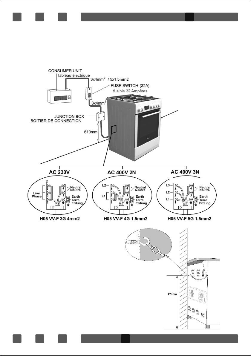
7.Before using the appliance, in order to ensure safe use, be sure to fix the
appliance to the wall using the chain and hooked screw supplied. Ensure that
the hook is screwed into the wall securely.
8.Please use flexible hose for gas connection.
230V~ 50-60Hz
230~/ 400V 2N~ 50-60Hz
Before using the appliance, in
order to ensure safe use, be sure
to fix the appliance to the wall
using the chain and hooked screw
supplied. Ensure that the hook is
screwed into the wall securely.
3
230~ / 400V 3N ~ 50-60Hz
1
Page 5
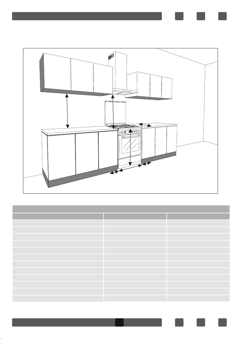
INSTALLATION OF YOUR OVEN
TECHNICAL FEATURES OF YOUR OVEN
SPECIFICATIONS
Outer width
Outer depth
Outer height
Inner width
Inner depth
Inner height
Inner Volume
Lamp power
Bottom heating element
Top heating element
Turbo heating element
Grill heating element
Min:570mm
Min:650mm
640mm
850mm
20mm
*Min:500-600mm
20mm
50x60 60x60
500 mm 600 mm
630 mm 630 mm
855 mm 855 mm
360 mm 460 mm
400 mm 400 mm
330 mm 330 mm
48 lt
15 W 15 W
1000 W 1200 W
800 W 1000 W
1800 W 2200 W
1500 W 2000 W
61 lt
4
Page 6
Supply Voltage
220V-240V AC,50-60Hz (Or 230V400V
AC,50-60 Hz)
1000 WHot Plate 145 mm
Hot Plate 180 mm
Hot Plate rapid 145 mm
Hot Plate rapid 180 mm
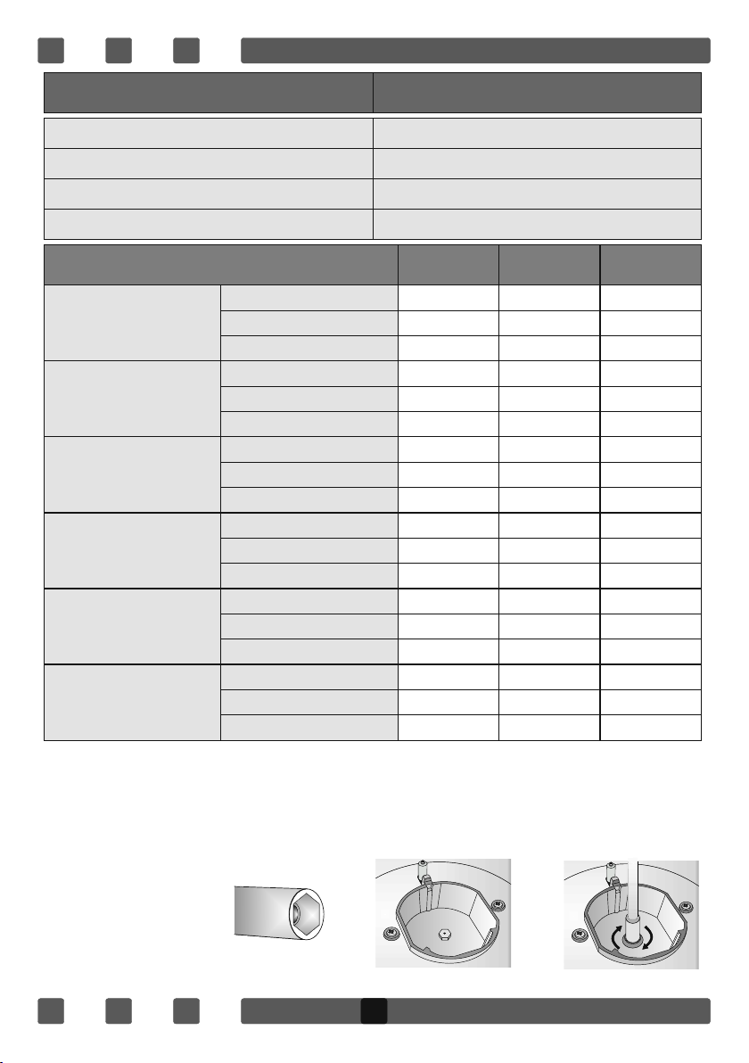
BURNER INJECTOR VALUES ACCORDING TO THE GAS
TYPE
Injector Ø mm
Wok Burner
Rapid Burner
Semi Rapid Burner
Auxiliary Burner
Oven Burner
Grill Burner
Power kW
Consuption Gr/h,m³/h
Injector Ø mm
Power kW
Consuption Gr/h,m³/h
Injector Ø mm
Power kW
Consuption Gr/h,m³/h
Injector Ø mm
Power kW
Consuption Gr/h,m³/h
Injector Ø mm
Power kW
Consuption Gr/h,m³/h
Injector Ø mm
Power kW
Consuption Gr/h,m³/h
LPG G30/28-
30mbar
0,96 1,30 1,40
3,60 3,35 3,66
284 0,3 0,365
0,85 1,15 1,20
3,00 2,77 3,00
286 0,253 0,326
0,65 0,97 0,95
1,78 1,78 1,61
140 0,167 0,174
0,50 0,72 0,70
0,88 0,99 0,88
70 0,092 0,094
0,70 0,97 0,95
2,16/2,22 1,83/2,00 1,72/1,70
170/175 0,178/0,179 0,183/0,178
0,60/0,65 0,95 0,92/0,95
1,50/1,72 1,78/1,85 1,50/1,60
118/135 0,162/0,169 0,162/0,173
1500 W
1500 W
2000 W
NG
G20/20mbar
NG
G25/25mbar
Nozzle change operation:
1. Please use driver with special head for removed and install nozzle as
figure-1
2. Please remove nozzle (Figure -2) from burner with special nozzle driver
and install new nozzle (Figure -3)
Fgure-1 Fgure-2 Fgure-3
5
Page 7
From LPG to NG
From NG to LPG
Rapid Burner
3 Turns Counterclockwise
3 Turns Clockwise
Semi-Rapid Burner
2.5 Turns Counterclockwise
2.5 Turns Clockwise
Auxiliary Burner
2 Turns Counterclockwise
2 Turns Clockwise
WOK Burner
4 Turns Counterclockwise
4 Turns Clockwise
Oven Burner
4,5 Turns Counterclockwise
4,5 Turns Clockwise
Grill Burner
4 Turns Counterclockwise
4 Turns Clockwise
GB
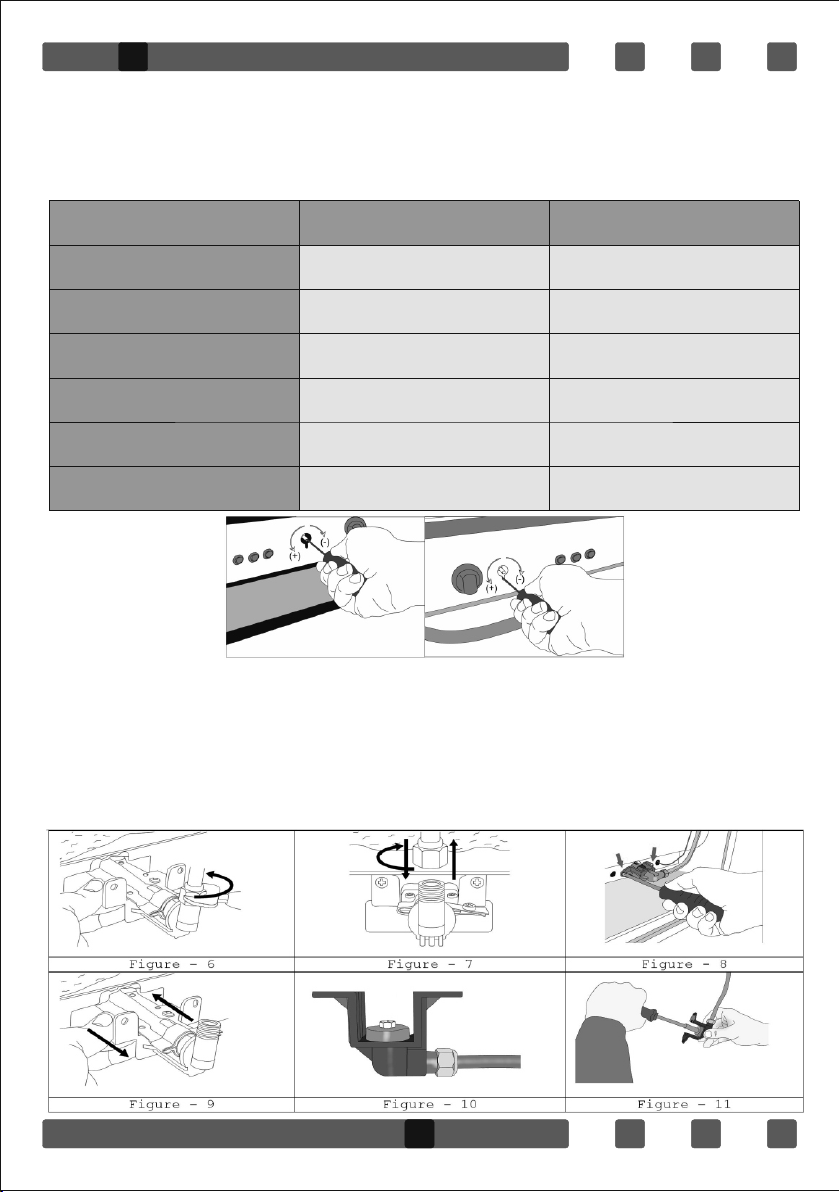
Reduced Flame Gas Cock Adjustment:
In order to adjust your oven to the gas type, make the adjustment for
reduced flame carefully by turning with a small screwdriver as shown below
on the screw in the middle of the gas cocks as well as nozzle changes.
Figure-4 Figure-5
For oven burners:
1.Please remove nut from on nozzle body with nutdriver and disconnect
gas pipe from body as Figure-6 and 7.
2.Please remove nozzle body and burner from cavity as Figure -8/9 and
remove nozzle from injector body (Figure-10/11) and change. Than reinstall nozzle body and burner on cavity by screws.
6
Page 8
If your oven has another type of oven burner, oven burner nozzle replacement
will be:
IMPORTANT WARNINGS:
1.Pay attention to minimum health and safety requirements.
2.The cooker is supplied setup according to the conditions shown on the
rating label which is stuck to the rear of the appliance. From this sticker you
can learn for which gas type (LPG or NG) this appliance is configured when
supplied.
3.Keep the electrical cable of your oven away from the hot areas.
4.If the supply cord is damaged, it must be replaced by the manufacturer its
services agent or similar qualified persons in order to avoid hazard.
5.Ensure that the appliance is switches off before replacing the lamp to avoid
the possibility of electric shock.
6.In case of power failure, readjust your timer definitely. Otherwise, the oven
will not operate (Digital Timer).
7.Your oven can be having different output pressure according your countries
gas and pressure specifications. Be sure that the cooker is configured
correctly for local requirements (for example, the jets must be suitable for local
gas type and gas pressure).
8.Connect your oven to LPG in shortest way and without any leakage. Min. 40
cm Max. 125 cm.
9.When making gas leakage check, never use any flame type like those of
lighter, matches, cigarette fire or similar ones.
10.Usage of your appliance creates moisture and heath in the room it is
placed, make sure that your kitchen is ventilated well. Maintain the natural
ventilation ducts properly.
7
Page 9

GB
11.CAUTION! Do not touch hot parts with bare hands and keep children
well supervised
12.When the oven is hot never touch the oven glass by hand.
13.Before starting to use your appliance, keep curtain, tulle, paper or
inflammable things away from your appliance. Do not keep combustible or
inflammable things in or on the appliance.
14.This appliance is for cooking purposes only. It must not be used for
other purposes, for example room heating. All our appliances are only for
domestic use, not for commercial use.
15.For disconnection from the supply mains having a contact separation in
all poles that provide full disconnection, must be incorporated in fixed
wiring in accordance with the wiring rules.
16.Some models are supplied without a plug-an-lead set. In this case
please use a flexible cable to suitable for connection to mono phase: H05
VV-F 3 G 4 mm2 or for 3 phase: H05 VV-F 5 G 1.5 mm2
17.This appliance is produced in accordance with the safety regulations.
Incorrect use will harm people and appliance.
18.Children should be supervised to ensure that they do not play with the
appliance. Never let them play with the appliance.
19.Unattended cooking on a hob with fat or oil can be dangerous and may
result in fire.NEVER try to extinguish a fire with water, but switch off the
appliance and then cover flame e.g. with a lid or a fire blanket.
20.Danger of fire: do not store items on the cooking surfaces
19.This appliance is not intended for use by persons (including children)
with reduced physical, sensory and mental capabilities or lack of
experience and knowledge, unless they have been given supervision or
instruction concerning the use of the appliance by a person responsible for
their safety.
20.“Caution: Accessible parts may be hot when the grill is in use. Young
children should be kept away”
IF THE APPLIANCE DOES NOT OPERATE
1.Please check the plug of power supply cord has a well connection with
wall socket or not.
2.Please check the electric network.
3.Please check the fuse.
8
Page 10

4.Please check power supply cord for any damage problems.
5.If you can not solve the problem, get in contact with manufacturer-
supplier service agent or similar qualified persons.
DESCRIPTION OF OVEN and CONTROL PANELS
Turnspt Fan
Top + Bottom heatng element Turbo heatng + Fan
Lamp Bottom + Top heatng elements + Fan
Bottom heatng element + Fan Grill heating element+fan
Grill heating e Grill burner / grill heating element
Grill heating element+lamp Top heating element
Electrical timer Oven burner / Bottom heating element
Flame Ignition lighter
THERMOSTAT KNOB; In order to operate the oven, thermostat must be
adjusted to desired temperature. Your thermostat has a feature of
adjustment to 50 - 280 degree.
MECHANIC TIMER KNOB (Optional); In order to operate the oven, timer
switch should be adjusted to desired time from 0-90 minute. You can use
cooking time table.
DESCRIPTION OF THE OVEN and CONTROL PANELS
7
1-Rapid burner
2-Semi-rapid burner
2
1
3
66
4
5
8
9
3-Auxiliary burner
4-Command panel
5-Oven handle
6-Top plate
7-Top lid (glass or metal)
8-Oven door
9-Dish warmer Drawer
9
Page 11

WOK Burner
24-28cm
Big Burner
22-26cm
Normal Burner
18-22cm
Small Burner
12-18cm
GB
USING COOKER SECTION
Using Gas Burners:
Closed
Fully open
Half open
1.In order to obtain maximum output, be careful that the saucepan which
will be used should be flat bottomed, and use the saucepans with
dimensions given herein above.
2.The valves controlling the gas cookers have special security mechanism.
In order to light the cooker;
Always press on the switch forward and bring it to flame symbol by turning
counterclockwise. All of the lighters shall operate and the cooker you
controlled shall light only. Keep the switch pressed until ignition is
performed. Press on the lighter button and turn the knob counter
clockwise.
3.Do not continuously operate the igniter for more than 15 seconds. If the
burner does not ignite, wait minimum one minute before try again. If the
burner is extinguished because of any reason, close the gas control valve
and wait minimum one minute before try again.
4.In models with Gas Security System, when flame of the cooker is
extinguished, control valve cuts off the gas automatically. For operate the
burners with gas security system you must press the knob and turn
counter-clock-wise. After the ignition you must wait nearly 5-10 second for
gas security systems activation. If the burner is extinguished for of the any
reason, close the gas control valve and wait a minimum of one minute
before trying again.
Using Hot Plates:
145 mm
180 mm
145 mm rapd
180 mm rapd
LEVEL 1
95 W
115 W
135 W
175 W 220 W
LEVEL 2
155 W
175 W
165 W
LEVEL 3
250 W
250 W
250 W
300 W
LEVEL 4
400 W
600 W
500 W
850 W
LEVEL 5
750 W
850 W
750 W
1150 W
LEVEL 6
1000 W
1500 W
1500 W
2000 W
10
Page 12

1.Electric hotplates have standard of 6 temperature levels (as described
herein above)
2.When using first time, operate your electric hotplate in position 6 for 5
minutes. This will make the agent on your hotplate which is sensitive to heat
get hardened by burning.
3.Use flat bottomed saucepans which fully contact with the heat as much as
you can, so that you can use the energy more productively.
Before operating your hob please make sure that the burner caps are well
positioned. The right placement of the burner caps are shown as below.
USING OVEN SECTION
Using oven burners:
1.If your oven equipped with burners that operates with gas, appropriate
knob should be used in order to ignite the burners. Some models have
automatic ignition from the knob; it is easy to ignite the burner by turning
the knob. Also, burners can be ignited by pressing the ignition button or
they can be ignited with a match.
2.Do not continuously operate the igniter for more than 15 seconds. If the
burner does not ignite, wait minimum one minute before trying again. If the
burner is extinguished for of the any reason, close the gas control valve and
wait a minimum of one minute before trying again.
11
Page 13

GB
Using oven heating elements:
1.When your oven is operated first time, an odor will be spread out which will
be sourced from using the heating elements. In order to get rid of this,
operate it at 250 °C for 45-60 minutes while it is empty.
2.Oven control knob should be positioned to desired value; otherwise oven
does not operate.
3.Kinds of meals, cooking times and thermostat positions are given in
cooking table. The values given in the cooking table are characteristic values
and were obtained as a result of the tests performed in our laboratory. You
can find different flavors suitable for your taste depending on your cooking
and using habits.
4.You can make chicken revolving in your oven by means of the accessories.
5.Cooking times: The results may change according to the area voltage and
material having different quality, amount and temperatures.
6.During the time when cooking is being performed in the oven, the lid of the
oven should not be opened frequently. Otherwise circulation of the heat may
be imbalanced and the results may change.
7.Using cake forms while cooking cake gives better result.
8.5 - 10 min. preliminary heating should be done prior cooking.
Cooking Time Table:
Meals
Creamed cake
Pastry
Biscuit
Cookie
Cake
Braided cookie
Filo Pastry
Savory pastry
Lamb meat
Veal
Mutton
Chicken (pieced)
Fish
Temperature (°C)
150-170
200-220
160-170
160-170
160-180
200-220
180-220
160-180
210-230
210-230
210-230
210-230
190-210
12
Rack position
2
2
3
3
2
2
2
2
1
1
1
1
3
Cooking time (min.)
30-35
35-45
20-25
20-35
25-35
30-40
35-45
20-30
90-120
90-120
90-120
75-100
40-50
Page 14

MAINTENANCE and CLEANING
1.Disconnect the plug supplying electricity for the oven from the socket.
2.While oven is operating or shortly after it starts operating, it is extremely hot.
You must avoid touching from heating elements.
3.Never clean the interior part, panel, lid, trays and all other parts of the oven
by the tools like hard brush, cleaning mesh or knife. Do not use abrasive,
scratching agents and detergents.
4.After cleaning the interior parts of the oven with a soapy cloth, rinse it and
then dry thoroughly with a soft cloth.
5.Clean the glass surfaces with special glass cleaning agents.
6.Do not clean your oven with steam cleaners.
7.Before opening the upper lid of the oven, clean spilled liquid off the lid. Also,
before closing the lid, ensure that the cooker table is cooled enough.
8.Never use inflammable agents like acid, thinner and gasoline when
cleaning your oven.
9.Do not wash any part of your oven in dishwasher.
10.In order to clean the front glass lid of the oven; remove the fixing screws
fixing the handle by means of a screwdriver and remove the oven door. Than
clean and rinse it thoroughly. After drying, place the oven glass properly and
re-install the handle.
2
1
3
1
2
4
13
Page 15

CLEANING AND MAINTENANCE OF THE OVEN'S FRONT DOOR GLASS
Remove the profile by pressing the plastic latches on both left and right sides
as shown in Figure 1 and pulling the profile towards yourself as shown in
Figure 2. Then remove the inner-glass as shown in Figure 3. If required,
middle glass can be removed in the same way. After cleaning and
maintenance are done, remount the glasses and the profile in reverse order.
Make sure the profile is properly seated in its place.
Figure 2Figure 1
Figure 3
USAGE OF COFFEEPOT SUPPORT:
Coffeepot support is to use small diameter pots with your cooker. Place
the support part on the grid centerly and then put the pot on it to start
using.
15
14
Page 16

ESP
ESP
Muy estimado cliente,
Estas instrucciones de uso contienen indicaciones importantes
acerca de la seguridad, la instalación / montaje, el empleo y el
cuidado del equipo.
Por este motivo le recomendamos leerlas cuidadosamente antes
de empezar a utilizar el producto y guardarlas para poderlas
volver a consultar en caso de necesidad.
Observación:
Estas instrucciones de uso han sido creadas para varios
modelos. Algunas de las propiedades indicadas en estas
instrucciones pueden diferir de las del equipo que usted ha
adquirido.
Atención: Todos nuestros aparatos son sólo para el uso
doméstico, no para el uso comercial
ESTE EQUIPO SE HA DE INSTALAR EN CONFORMIDAD CON LA NORMATIVA
VIGENTE Y SOLO PUEDE SER UTILIZADO EN LUGARES BIEN VENTILADOS. LEA
LAS INSTRUCCIONES ANTES DE INSTALARLO O EMPEZAR A UTILIZARLO.
ÍNDICE DE CONTENIDOS
Pagina
Indicaciones de instalación y seguridad
Información técnica
Si la cocina de gas deja de funcionar
A continuación se explica el significado de los símbolos
utilizados en el marco de manejo
Descripción del equipo
Manejo de los fogones
Manejo del horno
Limpieza y cuidados
15
15
Page 17

Indicaciones de instalación y seguridad
CONEXIÓN ELÉCTRICA
1.Esta cocina de gas necesita fusibles de 16 amperios. El enchufe del
equipo solo puede conectarse a una toma de corriente que esté
debidamente conectada a tierra.
2.Este equipo está diseñado para una alimentación de tensión de 230 V,
50 Hz. Si la red eléctrica principal del lugar donde se va a conectar el
equipo no cumple este requisito, diríjase a un punto de servicio autorizado.
3.Proporcione una buena ventilación al lugar (sin corrientes de aire). Este
equipo solo puede ser instalado en espacios que cumplan las normativas
aplicables. Efectúe los trabajos de limpieza y conservación de los
conductos de aire de forma regular.
4.En caso de resultar dañada la línea de alimentación, ésta deberá ser
reemplazada por un técnico de servicio o un técnico electricista autorizado
para evitar posibles peligros.
5.Durante la conexión y el manejo del equipo, preste atención a que la
línea de alimentación no entre en contacto con otras superficies calientes
CONEXIÓN DE GAS
Antes de instalar o cambiar un equipo de gas se ha de informar a la empresa
suministradora de gas local.
1.La instalación y la conexión del equipo solo puede ser efectuada a través
de una empresa registrada en la lista de instaladores o de un servicio de
asistencia técnica bajo contrato.
2.La conexión o el cambio a otro tipo de gas se ha de efectuar conforme a
las normas de conexión aplicables:
3.Gas natural: Normas técnicas para instalaciones de gas (TRGI)
4.Gas licuado de petróleo: Normas técnicas para gas licuado de petróleo
(TRF)
5.Tenga en cuenta las prescripciones aplicables al empleo de equipos de
gas.
6.Encontrará las especificaciones de la cocina de gas y su equipamiento
en la ficha de características que hay en la parte posterior de la misma
(GLP o gas natural –GN-).
7.En caso de utilizar gas natural la conexión se ha de efectuar con una
manguera de seguridad para gas y una toma de gas con un dispositivo de
cierre térmico (TAE).
16
Page 18

ESP
8.En caso de utilizar gas licuado de petróleo se ha de conectar una
pequeña instalación de gas con TAE.
9.No permita que las líneas de alimentación (eléctricas y de gas) entren en
contacto con las piezas calientes.
10.En caso de producirse daños en las líneas de alimentación, un técnico
deberá reemplazarlas por las líneas correspondientes para evitar posibles
peligros.
11.ATENCIÓN: A fin de evitar descargas eléctricas, compruebe que el
equipo está desconectado de la red antes de cambiar la lámpara del
horno.
12. ATENCIÓN: ¡La presencia de fugas solo puede ser comprobada por
un técnico!
13.Durante la búsqueda de fugas no encienda encendedores, cerillas,
cigarrillos ni materiales inflamables.
14.Durante el funcionamiento del horno se calientan varias piezas
descubiertas tales como los mandos, el marco de manejo y la plancha
exterior del horno; mantenga a los niños alejados de estas piezas.
15.No utilice el equipo como una estufa.
16.Cuando el equipo de gas esté en funcionamiento, mantenga alejados
todos los materiales inflamables tales como cortinas, tules, papeles y otros.
No coloque materiales inflamables o combustibles en el interior ni encima
del aparato. En el carro solo se pueden colocar: vajilla o bandejas para
hornos y otros materiales no inflamables.
En caso de producirse un escape de gas:
- cierre la válvula de la instalación o la bombona de gas
- apague todos los quemadores y otras fuentes de encendido.
- ventile la habitación; abra las ventanas y las puertas
- no conecte ningún aparato eléctrico (tampoco la luz)
- informe de la fuga de gas al servicio técnico autorizado inmediatamente
Atención: La conexión incorrecta o realizada por terceros invalidará todas
las responsabilidades y el derecho a garantía.
15
17
Page 19

Antes de usar el artefacto, y a fin de lograr un uso
seguro, no olvide sujetar el artefacto al muro utilizando
la cadena y el tornillo en gancho provisto. Verifique
que el gancho esté atornillado en el muro firmemente
Min:570mm
Min:650mm
640mm
850mm
*Min:500-600mm
20mm
18
20mm
Page 20

ESP
Información técnica
PROPIEDADES
ANCHURA EXTERIOR
PROFUNDIDAD EXTERIOR
ALTURA EXTERIOR
ANCHURA HORNO
PROFUNDIDAD HORNO
ALTURA HORNO
Potencia Lámparas *
Termostato
Calefacción botón
Elemento de calentamiento
Elemento de calentamiento
turbo *
Elemento calefactor
parrilla *
TENSIÓN DE ALIMENTACIÓN
calefacción
calefacción
calefacción
calefacción
Modelo de tubo según tipo de
Quemador Wok
Quemador de gas
grande
Calent.
Calent.
Quemador de gas
mediano
Quemador de gas
pequeño
Superior horno
inferior horno
de la
ø140*
ø180*
ø140*rapid
ø180*rapid
gas
Tubo
Línea
Tubo
Línea
Tubo
Línea
Tubo
Línea
Tubo
Línea
Tubo
Línea
50 x 55
500 mm
550 mm
855 mm
360 mm
400 mm
350 mm
1000 W
800 W
--
1500 W
220 -240 V AC, 50 - 60 Hz ( 230V/400V AC, 50 - 60 Hz.)
mm
KW
mm
KW
mm
KW
mm
KW
mm
KW
mm
KW
G 30 - 30
2.16 / 2.22
0.60 / 0.65
2.22 / 1.72
LPG
0.96
3.60
0.85
3.00
0.65
1.78
0.50
0.88
0.70
50 x 60
500 mm
630 mm
855 mm
360 mm
400 mm
350 mm
1000 W
800 W
1800 W
1500 W
50 – 280 °C
1000 W
1500 W
1500 W
2000 W
Gás Natural
G 20 - 20
1.30
3.35
1.15
2.77
0.97
1.78
0.72
0.99
0.97
1.83 / 2.00
0.95
1.78 / 1.85
15 W
60 x 58
600
580 mm
855 mm
460 mm
400 mm
350 mm
mm
60 x 60
600 mm
630 mm
855 mm
460 mm
400 mm
350 mm
1200 W
1000 W
2200 W
2000 W
1200 W
1000 W
2200 W
2000 W
Gás Natural
G 25 - 25
1.40
3.66
1.20
3.00
0.95
1.61
0.70
0.88
0.95
1.72 / 1.70
0.92 / 0.95
1.50 / 1.60
FUEGO PEQUEÑO - Ajuste
Al cambiar el tipo o la presión del
gas se ha de prestar atención a lo
siguiente:
Para ajustar el horno de acuerdo
con el tipo y la presión del gas,
además de cambiar los tubos también
es necesario ajustar la cantidad
del caudal de gas para cada fogón
(tornillo de ajuste junto al
regulador; accesible al desmontar
el mando).
Figura - 1 Figura - 2 Figura - 3
Quemador
grande
Quemador
mediano
Quemador
pequeño
15
19
De GLP a gas natural
3 vueltas en sentido
contrario a las
agujas del reloj
2,5 vueltas en
sen tido contrario a
las agujas del reloj
2 vueltas en sentido
contrario a las
agujas del reloj
De gas natural a
GLP
3 vueltas en
sentido de las
agujas del reloj
2,5 vueltas en
sentido de las
agujas del reloj
2 vueltas en
sentido de las
agujas del reloj
Page 21

Si la cocina de gas deja de funcionar
1.Compruebe si está abierta la válvula de gas principal.
2.Compruebe si la manguera de gas está conectada correctamente a la
cocina.
3.Compruebe si sale gas por los fogones después de abrir la válvula.
4.Si el horno sigue sin funcionar después de efectuar estos controles,
póngase en contacto con un técnico o con el punto de servicio técnico más
cercano.
20
Page 22

ESP
A continuación se explica el significado de los símbolos utilizados en el
marco de manejo
Asado (pollo cocinado)
Cocinar por la única es la parte superior del
horno
Luz
Cocinar por la única y funcionamiento del
ventlador
Cocinar con la parrilla+ Asado (pollo
cocinado)
Cocinar con la parrilla+ Luz
Temporizador
llama
Descripción del equipo
3
Operación de cocción ventilador
Operación de cocción ventilador turbo
Convección, el ventilador está funcionando
Cocinar con la parrilla+ ventilador
Cocinar con la parrilla
Cocinar con la parte superior
Cocinar por la única
PULSADOR DE ENCENDIDO
1. Quemador Grande
7
2
1
66
4
5
8
9
2. Quemador médo
3. Quemador pequeno
4. Marco de manejo
5. Empuñadura de la
6. Espaco de cocna
7. Tapa abatble
8. la puerta del horno
9. plato calente
repartr el c a jón
10.
11. Chapa de calor (solo con
calentador
Manejo de los fogones
Prestar atención a los fogones:
Utilice utensilios de cocina adecuados para cada quemador.
Todos los quemadores están equipados con válvulas de seguridad
especiales. Para encender los fogones tenga en cuenta lo siguiente:
15
21
Page 23

Quemador grande
Quemador medano
Quemador pequeño
Ollas de 24
Ollas de 18 – 22 cm
Ollas de 12 – 18 cm
1. Presione el mando (conmutador) respectivo hacia dentro y gírelo en
–
28 cm
CERRADO
TOTALMENTE
ABIERTO
SEMIABIER-TO
sentido contrario a las agujas del reloj hasta que esté seleccionado el
símbolo de llama al máximo.
2. Presione el pulsador de encendido. Se activan todos los quemadores
pero solo se puede encender el fogón seleccionado.
Importante: Cuando la llama se apaga el sistema de seguridad del gas
desconecta automáticamente la alimentación de gas mediante una válvula
de mando
Todos los fogones de la cocina y del horno funcionan independientemente.
Para encender un fogón es necesario apretar el mando correspondiente y
esperar durante 5 – 10 segundos aproximadamente.
TABLA DE HORNEADO Y ASADO
ALIMENTOS
PASTELES DE NATA
GALLETAS RELLENAS
VOLOVÁN DE HOJALDRE
PASTELES
BIZCOCHOS
GALLETAS
PASTELES
PASTAS DULCES
CORDERO
TERNERA
POLLO (PIEZA)
PESCADO
OVEJA
TEMPERATURA
150 - 170
200 - 220
160 - 170
160 - 170
160 - 180
200 - 220
180 - 220
160 - 180
200 - 230
200 - 230
210 - 230
210- 230
190- 210
POSICIÓN
2
2
3
3
2
2
2
2
1
1
1
1
2
TIEMPO DE HORNEADO O
ASADO (mnutos)
30 - 35
35 - 45
20 - 25
20 - 35
25 - 35
30 - 40
35 - 45
20 - 30
90- 120
90- 120
90- 120
75- 100
40- 50
Observación: Los valores indicados en la tabla son promedios calculados
que pueden no corresponderse con sus necesidades personales. Antes de
hornear o asar, caliente el horno durante 5 – 10 minutos.
A continuación podrá encender el gas electrónicamente presionando el
pulsador de encendido o manualmente con una cerilla. Después de
encender el fuego mantenga el mando del gas presionado durante unos
segundos y luego suéltelo.
22
Page 24

ESP
Para encender los quemadores del horno deje la puerta abierta. Ciérrela
aproximadamente 3 segundos después de que la llama se haya encendido
y de comprobar que quema correctamente.
Manejo del horno
1. La primera vez que utilice el horno es posible que oiga un ruido
molesto. Preste atención a que la habitación esté suficientemente
ventilada y caliente el horno vacío durante aproximadamente 30 minutos
a 250 ºC.
2.Encienda el horno (véase „Manejo de los fogones“).
3.En la tabla de horneado y asado se indican los tipos de alimentos, los
tiempos de horneado y asado y la posición correcta del termostato para
cada uno de ellos.
4.Los valores de la tabla son promedios que han sido obtenidos en los
ensayos realizados en nuestros laboratorios.
5.En función del estilo de horneado y asado que utilice y de sus propias
costumbres podrá preparar distintos platos.
6.Tiempos de horneado y asado: Éstos tiempos sirven solo como
referencia, ya que los materiales, las cantidades y los alimentos
utilizados pueden dar distintos resultados en función de la temperatura
utilizada
7.No abra la puerta del horno durante las operaciones de horneado y
asado (pérdida de calor).
8.Ello podría perjudicar el resultado del horneado o el asado
9.A fin de obtener mejores resultados cuando haga pasteles,
recomendamos utilizar moldes de horno apropiados
10. No coloque sartenes, ollas ni bandejas sobre el fondo del horno para
asar o mantener la comida caliente.
11. No coloque papel de aluminio ni ningún otro tipo de material sobre el
fondo del horno.
12. Ello podría estropear el esmalte.
13. No deje enfriar la comida dentro del horno (el horno podría oxidarse).
14. Ello invalidará el derecho a garantía.
15
23
Page 25

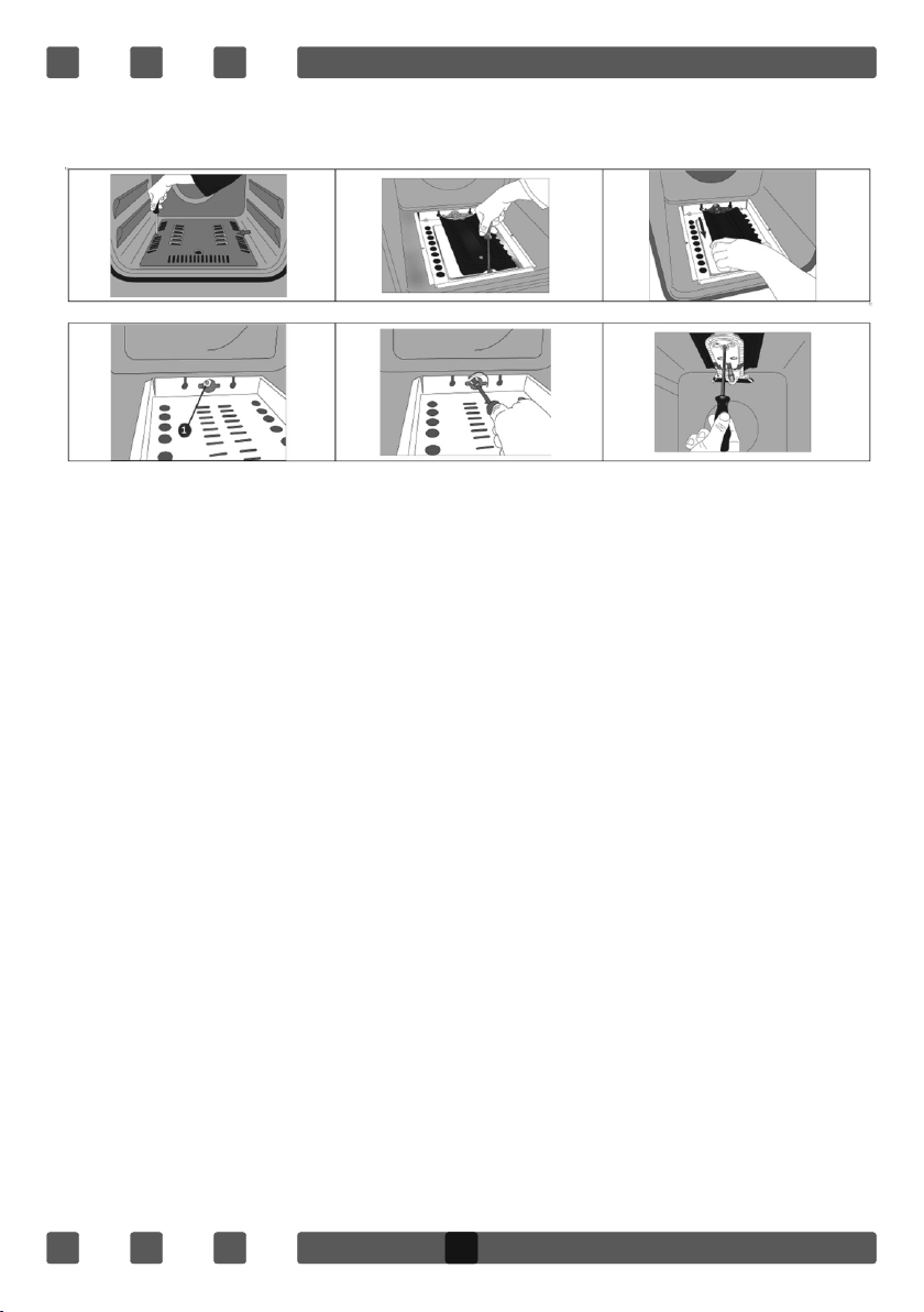
USO DE LA PLACA DE PROTECCIÓN
1. Para proteger el panel de control del horno, una placa fue diseñada.
(Figura 1)
2. Recomendamos el uso de esta pieza de protección para evitar daños
que pueden ser causados p or el calor durante la cocción.
3. Coloque la hoja de protección en el panel de control mediante la
apertura del horno (Figura 2)
4. Asegúrese de que la placa está bien posicionada cerca de su horno
(Figura 3)
5. Es importante mantener la tapa abierta.
6. La placa le asegurara su seguridad y protegerá las partes del panel de
control.
Limpieza y cuidados
1.Cuando efectúe los trabajos de limpieza y cuidado preste atención a lo
siguiente:
2.Antes de empezar la limpieza o el mantenimiento del equipo, asegúrese
de que está desconectado de la red eléctrica y de que está cerrada la
alimentación de gas.
3.Si el equipo todavía está caliente, déjelo enfriar el tiempo suficiente antes
de empezar la limpieza o el mantenimiento.
4.Cuando efectúe los trabajos de limpieza y cuidado preste atención a lo
siguiente:
5.Antes de empezar la limpieza o el mantenimiento del equipo, asegúrese
de que está desconectado de la red eléctrica y de que está cerrada la
alimentación de gas.
6.Si el equipo todavía está caliente, déjelo enfriar el tiempo suficiente antes
de empezar la limpieza o el mantenimiento.
24
Page 26

ESP
1
1
2
LIMPIEZA Y MANTENIMIENTO DEL VIDRIO DE LA PUERTA FRONTAL DEL HORNO
Retire el perfil presionando los enganches plásticos tanto a la derecha como
a la izquierda según se indica en la Figura 1 y traccionando el perfil hacia
usted como se indica en la Figura 2. Luego retire el vidrio interno según se
indica en la Figura 3. Si es necesario, el vidrio del medio puede retirarse del
mismo modo. Una vez realizados la limpieza y el mantenimiento, vuelva a
instalar los vidrios y el perfil en el orden inverso. Asegúrese de que el perfil esté
correctamente asentado en su lugar.
3
2
4
Figura 3
25
Figura 2Figura 1
 Loading...