

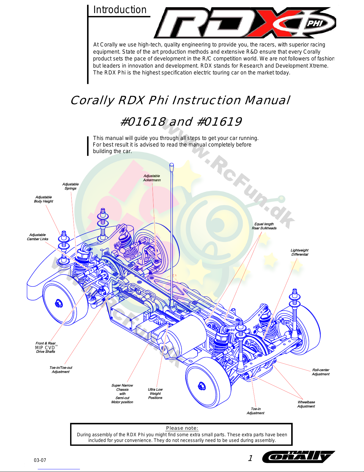
Corally RDX Phi Instruction Manual
Introduction
TM
MIP CVD
At Corally we use high-tech, quality engineering to provide you, the racers, with superior racing
equipment. State of the art production methods and extensive R&D ensure that every Corally
product sets the pace of development in the R/C competition world. We are not followers of fashio
n
but leaders in innovation and development. RDX stands for Research and Development Xtreme.
The RDX Phi is the highest specification electric touring car on the market today.
This manual will guide you through all steps to get your car running.
For best result it is advised to read the manual completely before
building the car.
1
-
During assembly of the RDX Phi you might find som e ex tra sm al l pa rts. These extra parts have been
included for your convenience. They do no t necessarily need to be used during assembly.
Please note:
#01618 and #01619
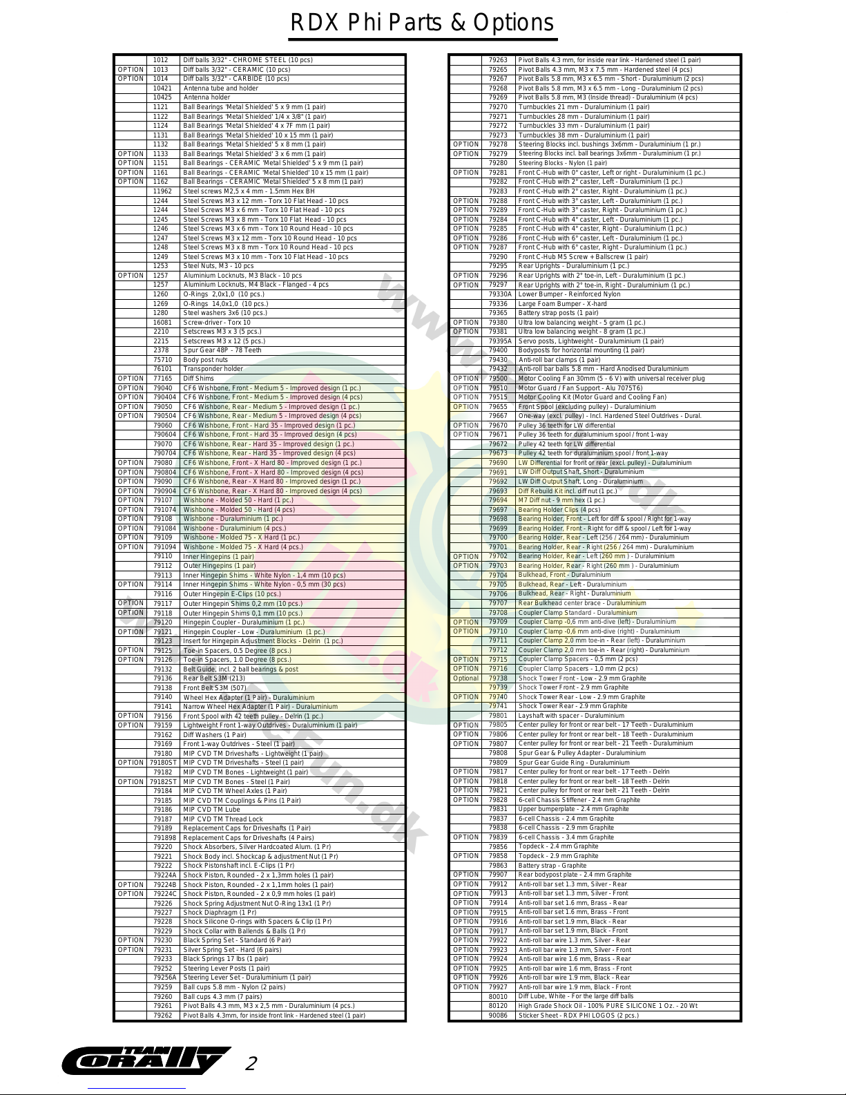
RDX Phi Parts & Options
1012
1013
1121
1131
1133
1132
1151
1161
1244
1280
16081
2378
2215
2210
1269
1249
1253
1248
1247
1246
1245
79121
79120
79116
79123
79138
79140
79136
79132
79126
79125
75710
791094
79110
79112
791084
79107
791074
77165
76101
79180
79184
79182
79162
79159
Toe-in Spacers, 1.0 Degree (8 pcs.)
MIP CVD TM Wheel Axles (1 Pair)
Diff Washers (1 Pair)
Wheel Hex Adapter (1 Pair) - Duraluminium
Lightweight Front 1-way Outdrives - Duraluminium (1 pair)
MIP CVD TM Driveshafts - Lightweight (1 pair)
MIP CVD TM Bones - Lightweight (1 pair)
Front Belt S3M (507)
Rear Belt S3M (213)
Belt Guide, incl. 2 ball bearings & post
Steel Screws M3 x 8 mm - Torx 10 Round Head - 10 pcs
Wishbone - Molded 50 - Hard (4 pcs)
Wishbone - Molded 50 - Hard (1 pc.)
Wishbone - Duraluminium (1 pc.)
Wishbone - Molded 75 - X Hard (4 pcs.)
Wishbone - Molded 75 - X Hard (1 pc.)
Wishbone - Duraluminium (4 pcs.)
Hingepin Coupl er - Low - Duraluminiu m (1 pc. )
Insert for Hingepin Adjustment Blocks - Delrin (1 pc.)
Toe-in Spacers, 0.5 Degree (8 pcs.)
Hingepin Coupler - Duraluminium (1 pc.)
Outer Hingepins (1 pair)
Outer Hingepin E-Clips (10 pcs.)
Inner Hingepins (1 pair)
Transponder holder
Diff Shims
Body post nuts
Steel Nuts, M3 - 10 pcs
Steel Screws M3 x 10 mm - Torx 10 Flat Head - 10 pcs
O-Rings 14,0x1,0 (10 pcs.)
Setscrews M3 x 3 (5 pcs.)
Setscrews M3 x 12 (5 pcs.)
Spur Gear 48P - 78 Teeth
Screw-driver - Torx 10
Steel washers 3x6 (10 pcs .)
Diff balls 3/32" - CHROME STEEL (10 pcs)
Diff balls 3/32" - CERAMIC (10 pcs)
Steel Screws M3 x 8 mm - Torx 10 Flat Head - 10 pcs
Steel Screws M3 x 6 mm - Torx 10 Round Head - 10 pcs
Steel Screws M3 x 12 mm - Torx 10 Round Head - 10 pcs
Steel Screws M3 x 6 mm - Torx 10 Flat Head - 10 pcs
Ball Bearings - CERAMIC 'Metal Shielded' 10 x 15 mm (1 pair)
Ball Bearings - CERAMIC 'Metal Shielded' 5 x 9 mm (1 pair)
Ball Bearings 'Metal Shielded' 5 x 8 mm (1 pair)
Ball Bearings 'Metal Shielded' 3 x 6 mm (1 pair)
Ball Bearings 'Metal Shielded' 10 x 15 mm (1 pair)
Ball Bearings 'Metal Shielded' 5 x 9 mm (1 pair)
Antenna holder
79109
79108
79230
MIP CVD TM Couplings & Pins (1 Pair)
79185
79229
79228
79227
79226
79224A
79222
79220
79189
79187
MIP CVD TM Lube
Shock Spring Adjustment Nut O-Ring 13x1 (1 Pr)
Shock Diaphragm (1 Pr)
Shock Silicone O-rings with Spacers & Clip (1 Pr)
Shock Piston, Rounded - 2 x 1,3mm holes (1 pair)
Shock Absorbers, Silver Hardco ated Alum. (1 Pr)
Shock Pistonshaft incl. E-Clips (1 Pr)
Shock Body incl. Shockcap & adjustment Nut (1 Pr)
Replacement Caps for Driveshafts (1 Pair)
MIP CVD TM Thread Lock
79186
79380
79430
79400
79395A
79381
79283
79297
79365
79330A
79296
79295
79290
79287
79286
79285
79284
79282
79281
79279
79273
79272
79271
79270
79265
79260
79256A
79252
79233
79231
79263
79221
Servo posts, Lightweight - Duraluminium (1 pair)
Bodyposts for horizontal mounting (1 pair)
Anti-roll bar clamps (1 pair)
Ultra low balancing weight - 8 gram (1 pc.)
Ultra low balancing weight - 5 gram (1 pc.)
Battery strap posts (1 pair)
Front C-Hub with 0° caster, Left or right - Duraluminium (1 pc.)
Front C-Hub with 6° caster, Left - Duraluminium (1 pc.)
Front C-Hub with 6° caster, Right - Duraluminium (1 pc.)
Front C-Hub M5 Screw + Ballscrew (1 pair)
Front C-Hub with 4° caster, Right - Duraluminium (1 pc.)
Front C-Hub with 4° caster, Left - Duraluminium (1 pc.)
Front C-Hub with 2° caster, Right - Duraluminium (1 pc.)
Front C-Hub with 2° caster, Left - Duraluminium (1 pc.)
Rear Uprights - Duraluminium (1 pc.)
Rear Uprights with 2° toe-in, Right - Duraluminium (1 pc.)
Rear Uprights with 2° toe-in, Left - Duraluminium (1 pc.)
Lower Bumper - Reinforced Nylon
Pivot Balls 4.3 mm, M3 x 7.5 mm - Hardened steel (4 pcs)
Turnbuckles 21 mm - Duraluminium (1 pair)
Turnbuckles 28 mm - Duraluminium (1 pair)
Turnbuckles 33 mm - Duraluminium (1 pair)
Steering Blocks incl. ball bearings 3x6mm - Duraluminium (1 pr.)
Turnbuckles 38 mm - Duraluminium (1 pair)
Silver Spring Set - Hard (6 pairs)
Black Spring S et - Standard (6 Pair)
Shock Collar with Ballends & Balls (1 Pr)
Black Springs 17 lbs (1 pair)
Ball cups 4.3 mm (7 pairs)
Pivot Balls 4.3 mm, for in side rear link - Hardened steel (1 pair)
Steering Lever Set - Duraluminium (1 pair)
Steering Lever Posts (1 pair)
OPTION
OPTION
OPTION
OPTION
OPTION
OPTION
OPTION
OPTION
OPTION
OPTION
OPTION
OPTION
OPTION
OPTION
OPTION
OPTION
OPTION
1122
Ball Bearings 'Metal Shielded' 1/4 x 3/8" (1 pair)
OPTION
791898
Replacement Caps for Driveshafts (4 Pairs)
OPTION
1162
Ball Bearings - CERAMIC 'Metal Shielded' 5 x 8 mm (1 pair)
Diff balls 3/32" - CARBIDE (10 pcs)1014
1257 Aluminium Locknuts, M4 Black - Flanged - 4 pcs
Narrow Wheel Hex Adapter (1 Pair) - Duraluminium
79141
2
MIP CVD TM Bones - Steel (1 Pair)79182STOPTION
Large Foam Bumper - X-hard79336
10425
OPTION
OPTION
OPTION
OPTION
790704
790604
79040
790504
79050
790404
CF6 Wishbone, Front - Medium 5 - Improved design (4 pcs)
CF6 Wishbone, Rear - Medium 5 - Improved design (1 pc.)
CF6 Wishbone, Rear - Medium 5 - Improved design (4 pcs)
CF6 Wishbone, Front - Medium 5 - Improved design (1 pc.)
CF6 Wishbone, Front - Hard 35 - Improved design (1 pc.)
CF6 Wishbone, Rear - Hard 35 - Improved design (4 pcs)
CF6 Wishbone, Rear - Hard 35 - Improved design (1 pc.)
CF6 Wishbone, Front - Hard 35 - Improved design (4 pcs)
79070
79060
790804
79080 CF6 Wishbone, Front - X Hard 80 - Improved design (1 pc.)
CF6 Wishbone, Front - X Hard 80 - Improved design (4 pcs)
79090
790904
CF6 Wishbone, Rear - X Hard 80 - Improved design (4 pcs)
CF6 Wishbone, Rear - X Hard 80 - Improved design (1 pc.)
Outer Hingepin Shims 0,2 mm (10 pcs.)
79117
Outer Hingepin Shims 0,1 mm (10 pcs.)79118
Front Spool with 42 teeth pulley - Delrin (1 pc.)
79156
Front 1-way Outdrives - Steel ( 1 pair)79169
79180ST
OPTION
MIP CVD TM Driveshafts - Steel (1 pair)
79224B Shock Piston, Rounded - 2 x 1,1mm holes (1 pair)
Shock Piston, Rounded - 2 x 0,9 mm holes (1 pair)79224C
Ball cups 5.8 mm - Nylon (2 pairs)
79259
Pivot Balls 4.3 mm, M3 x 2,5 mm - Duraluminium (4 pcs.)79261
Pivot Balls 4.3mm, for in side front link - Hardened steel (1 pair)
79262
Steering Blocks incl. bushings 3x6mm - Duraluminium (1 pr.)
79278
79280
Steering Blocks - Nylon (1 pair)
79289
79288 Front C-Hub with 3° caster, Left - Duraluminium (1 pc.)
Front C-Hub with 3° caster, Right - Duraluminium (1 pc.)
OPTION
OPTION
Anti-roll bar balls 5.8 mm - Hard Anodised Duraluminium79432
Motor Cooling Fan 30mm (5 - 6 V) with universal receiver plug
79500
Motor Guard / Fan Support - Alu 7075T6)
79510
Motor Cooling Kit (Motor Guard and Cooling Fan)
79515
79655
Front Spool (excluding pulley) - Duraluminium
One-way (excl. pulley) - I n cl. Hardened Steel Outdrives - Dural.
79667
Pulley 36 teeth for LW differential
79670
79671
Pulley 36 tee th for duraluminium spool / front 1-way
Pulley 42 teeth for LW differential
79672
Pulley 42 tee th for duraluminium spool / front 1-way
79673
LW Differential for front or rear (excl. pulley) - Duraluminium
79690
LW Diff Output Shaft, Short - Duraluminium
79691
LW Diff Output Shaft, Long - Duraluminium
79692
Diff Rebuild Kit incl. diff nut (1 pc.)
79693
M7 Diff nut - 9 mm hex (1 pc.)
79694
Bearing Holder Clips (4 pcs)
79697
79698
Bearing Holder, Front - Left fo r d iff & spool / Right for 1-way
Bearing Holder, Front - Right for diff & spool / Left for 1-way
79699
Bearing Holder, Rear - Right (256 / 264 mm) - Duraluminium
Bearing Holder, Rear - Left (256 / 264 mm) - Duraluminium
79700
79701
79702
Bearing Holder, Rear - Left (260 mm ) - Duraluminium
Bearing Holder, Rear - Right (260 mm ) - Duraluminium
79703
79705
79704
Bulkhead, Front - Duraluminium
Bulkhead, Rear - Left - Duraluminium
Bulkhead, Rear - Right - Duraluminium
79706
79707
Rear Bulkhead center brace - Duraluminium
79708
Coupler Clamp Standard - Duraluminium
Coupler Clamp -0,6 mm anti-dive (left) - Duraluminium
79709
Coupler Clamp -0,6 mm anti-dive (right) - Duraluminium
79710
Coupler Clamp 2,0 mm toe-in - Rear (right) - Duraluminium
Coupler Clamp 2,0 mm toe-in - Rear (left) - Duraluminium
79711
79712
79716
79715
Coupler Clamp Spacers - 0,5 mm (2 pcs)
Coupler Clamp Spacers - 1,0 mm (2 pcs)
Shock Tower Front - 2.9 mm Graphite
Shock Tower Front - Low - 2.9 mm Graphite
79738
79739
79741
Shock Tower R ear - 2.9 mm Graphite
Shock Tower Rear - Low - 2.9 mm Graphite
79740
Center pulley for front or rear belt - 18 Teeth - Duraluminium
79806
Center pulley for front or rear belt - 21 Teeth - Duraluminium
79807
Center pulley for front or rear belt - 17 Teeth - Duraluminium
79805
79801
Layshaft with spacer - Duraluminium
Spur Gear & Pulley Adapter - Duraluminium
79808
6-cell Chassis Stiffener - 2.4 mm Graphite
79828
Center pulley for front or rear belt - 18 Teeth - Delrin
Center pulley for front or rear belt - 21 Teeth - Delrin
79821
79818
Center pulley for front or rear belt - 17 Teeth - Delrin
79817
Spur Gear Guide Ring - Duraluminium
79809
79914
Anti-roll bar set 1.6 mm, Brass - Rear
Anti-roll bar set 1.9 mm, Black - Front
79915
Anti-roll bar set 1.6 mm, Brass - Front
79916
Anti-roll bar set 1.9 mm, Black - Rear
79917
Topdeck - 2.4 mm Graphite
Topdeck - 2.9 mm Graphite
79839
79856
79838
6-cell Chassis - 3.4 mm Graphite
6-cell Chassis - 2.9 mm Graphite
6-cell Chassis - 2.4 mm Graphite
79837
Upper bumperplate - 2.4 mm Graphite
79858
79863
79907
Battery strap - Graphite
Rear bodypost plate - 2.4 mm Graphite
Anti-roll bar set 1.3 mm, Silver - Rear
79912
79913
Anti-roll bar set 1.3 mm, Silver - Front
79831
79924
79927
79926
79925
79922
Anti-roll bar wire 1.3 mm, Silver - Front
Anti-roll bar wire 1.9 mm, Black - Front
Anti-roll bar wire 1.9 mm, Black - Rear
Anti-roll bar wire 1.6 mm, Brass - Front
Anti-roll bar wire 1.3 mm, Silver - Rear
79923
Anti-roll bar wire 1.6 mm, Brass - Rear
1124
Ball Bearings 'Metal Shielded' 4 x 7F mm (1 pair)
Steel Screws M3 x 12 mm - Torx 10 Flat Head - 10 pcs1244
Aluminium Locknuts, M3 Black - 10 pcs1257
OPTION
Steel screws M2,5 x 4 mm - 1.5mm Hex BH11962
Inner Hingepin Shims - White Nylon - 0,5 mm (30 pcs)
79113
Inner Hingepin Shims - White Nylon - 1,4 mm (10 pcs)
79114
79267
Pivot Balls 5.8 mm, M3 x 6.5 mm - Short - Duraluminium (2 pcs)
Pivot Ball s 5.8 mm, M3 x 6. 5 mm - Long - Duraluminium (2 pcs)
Pivot Balls 5.8 mm, M3 (Inside thread) - Duraluminium (4 pcs)
79269
79268
OPTION
OPTION
OPTION
OPTION
OPTION
Optional
OPTION
OPTION
OPTION
OPTION
OPTION
OPTION
OPTION
OPTION
OPTION
OPTION
OPTION
OPTION
OPTION
OPTION
OPTION
OPTION
OPTION
OPTION
OPTION
OPTION
OPTION
OPTION
OPTION
OPTION
OPTION
OPTION
OPTION
OPTION
OPTION
OPTION
OPTION
OPTION
OPTION
OPTION
OPTION
OPTION
OPTION
OPTION
OPTION
OPTION
OPTION
OPTION
90086
Sticker Sheet - RDX PHI LOGOS (2 pcs.)
80120
High Grade Shock Oil - 100% PURE S ILICONE 1 Oz. - 20 Wt
80010
Diff Lube, White - For the large diff balls
OPTION
OPTION
OPTION
O-Rings 2,0x1,0 (10 pcs.)
1260
OPTION
OPTION
OPTION
OPTION
OPTION
OPTION
10421
Antenna tube and holder
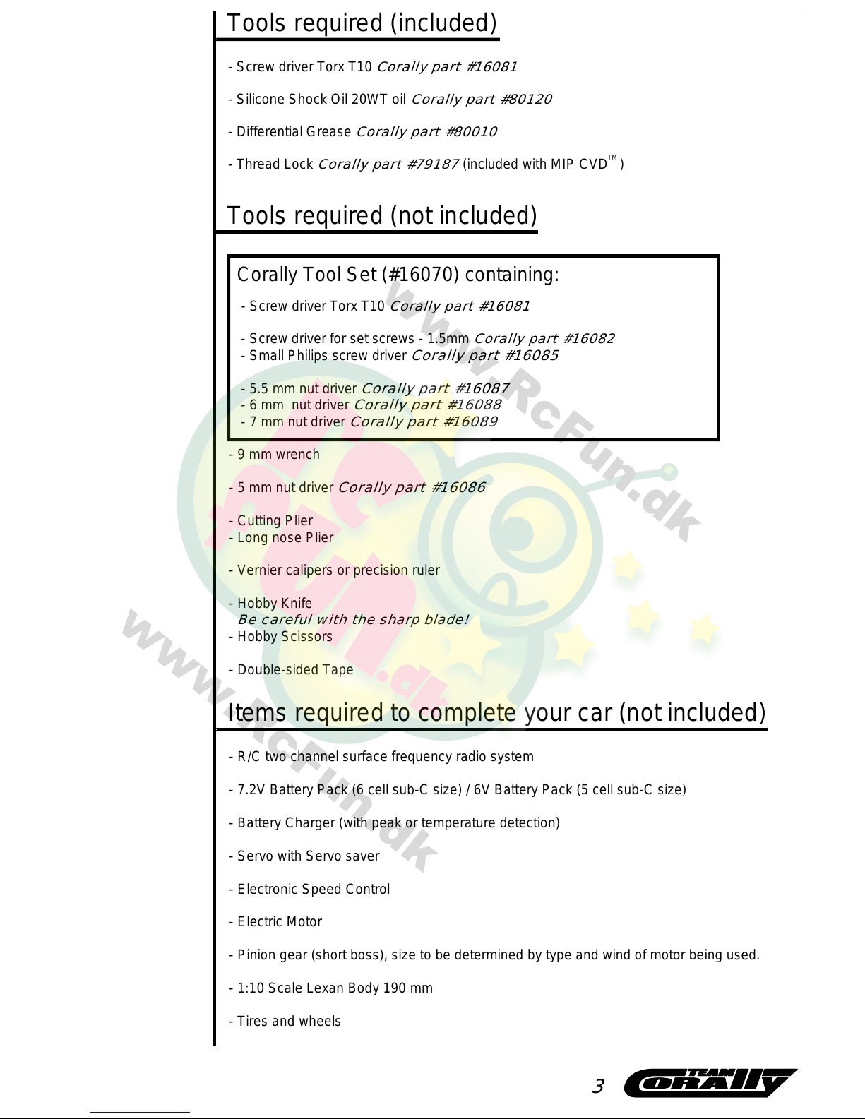
Tools required (not included)
- Screw driver Torx T10
Corally part #16081
- Screw driver for set screws - 1.5mm
Corally part #16082
- Small Philips screw driver
Corally part #16085
- 5.5 mm nut driver
Corally part #16087
- 6 mm nut driver
Corally part #16088
- 7 mm nut driver
Corally part #16089
- 9 mm wrench
- 5 mm nut driver
Corally part #16086
- Cutting Plier
- Long nose Plier
- Vernier calipers or precision ruler
- Hobby Knife
Be careful with the sharp blade!
- Hobby Scissors
- Double-sided Tape
Items required to complete your car (not included)
- R/C two channel surface frequency radio system
- 7.2V Battery Pack (6 cell sub-C size) / 6V Battery Pack (5 cell sub-C size)
- Battery Charger (with peak or temperature detection)
- Servo with Servo saver
- Electronic Speed Control
- Electric Motor
- Pinion gear (short boss), size to be determined by type and wind of motor being used.
- 1:10 Scale Lexan Body 190 mm
- Tires and wheels
- Screw driver Torx T10
Corally part #16081
- Silicone Shock Oil 20WT oil
Corally part #80120
- Differential Grease
Corally part #80010
- Thread Lock
Corally part #79187
(included with MIP CVD )
Tools required (included)
TM
Corally Tool Set (#16070) containing:
3
1x LW Diff Pulley 42T
4
2x Diff Washer
1x Ball Bearing 5x8
2x Ball Bearing 1/4 x 3/8"
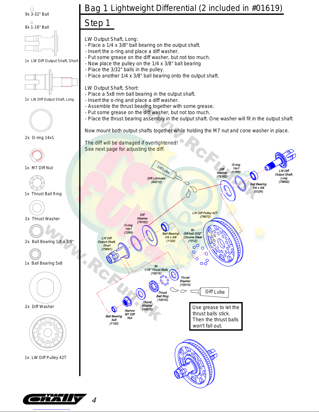
Use grease to let the
thrust balls stick.
Then the thrust balls
won't fall out.
D
i
f
f
L
u
b
e
LW Output Shaft, Long:
- Place a 1/4 x 3/8" ball bearing on the output shaft.
- Insert the o-ring and place a diff washer.
- Put some grease on the diff washer, but not too much.
- Now place the pulley on the 1/4 x 3/8" ball bearing
- Place the 3/32" balls in the pulley.
- Place another 1/4 x 3/8" ball bearing onto the output shaft.
LW Output Shaft, Short:
- Place a 5x8 mm ball bearing in the output shaft.
- Insert the o-ring and place a diff washer.
- Assemble the thrust bearing together with some grease.
- Put some grease on the diff washer, but not too much.
- Place the thrust bearing assembly in the output shaft. One washer will fit in the output shaft
.
Now mount both output shafts together while holding the M7 nut and cone washer in place.
The diff will be damaged if overtightened!
See next page for adjusting the diff.
1x M7 Diff Nut
1x Thrust Ball Ring
2x Thrust Washer
2x O-ring 14x1
D
i
f
f
L
u
b
e
1x LW Diff Output Shaft, Short
1x LW Diff Output Shaft, Long
9x 3-32" Ball
8x 1-16" Ball
Lightweight Differential (2 included in #01619)
Step 1
Bag 1

Step 2
Differential adjustment.
The differential should be carefully adjusted by holding the M7 nut using
a 9 mm wrench. Overtightening the M7 nut might damage the bearings,
balls and washers in the differential! To test for the correct adjustment,
hold both output shafts and try to spin the pulley. If the pulley slips without
using extreme force, it means the diff is too loose and needs to be
tightened some more by turning the M7 nut.
The differential should function smoothly.
Hold the M7 nut in
the output shaft with
a 9 mm wrench.
Differential Adjustment
The differential is an important component
of your car. So build and adjust it very carefully.
The RDX Phi (#01618) has a rear differential and front one-way.
The RDX Phi US Carpet Spec (#01619) comes with
two differentials.
5
Bag 2
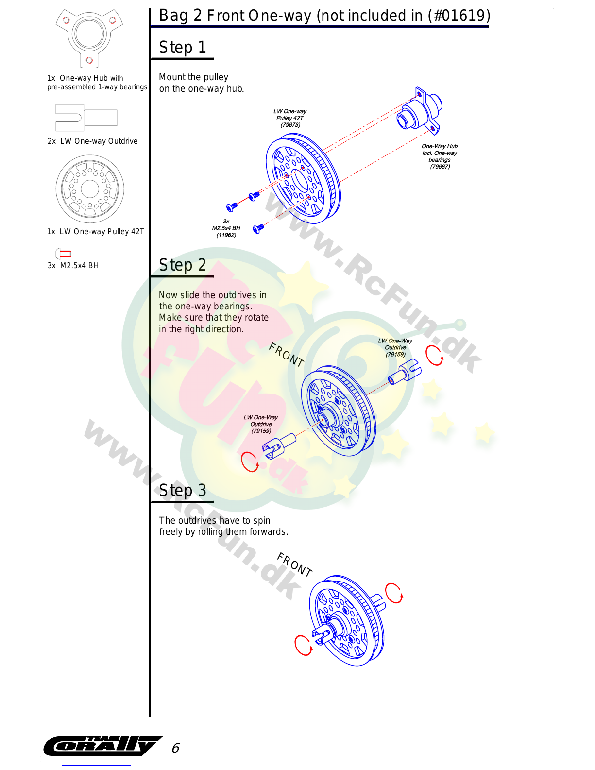
1x One-way Hub with
pre-assembled 1-way bearings
Front One-way (not included in (#01619)
Step 1
Mount the pulley
on the one-way hub
The outdrives have to spin
freely by rolling them forwards.
Now slide the outdrives in
the one-way bearings.
Make sure that they rotate
in the right direction.
Step 3
1x LW One-way Pulley 42T
3x M2.5x4 BH
Step 2
F
R
O
N
T
6
F
R
O
N
T
2x LW One-way Outdrive
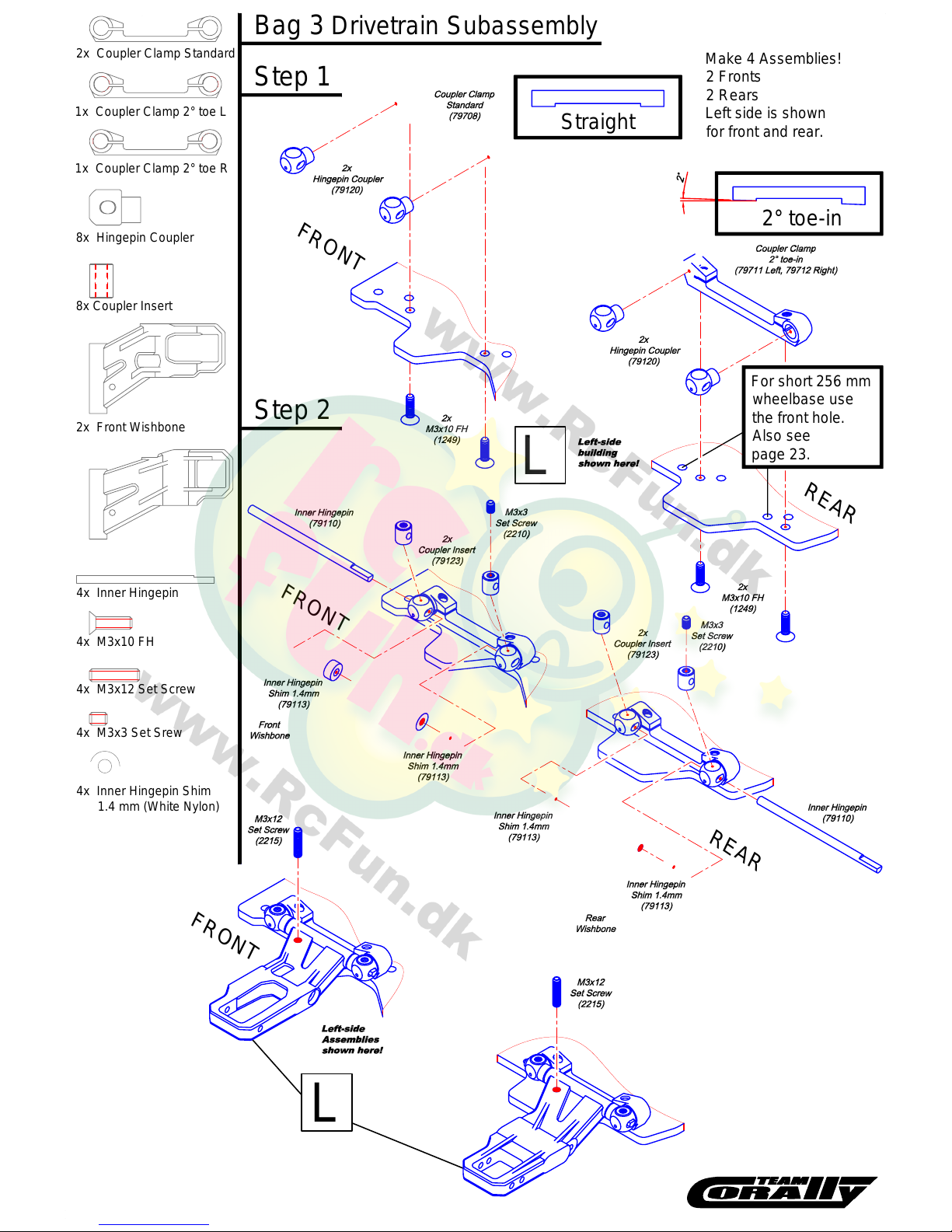
Step 1
Step 2
Make 4 Assemblies!
2 Fronts
2 Rears
Left side is shown
for front and rear.
L
L
R
E
AR
F
R
O
N
T
8x Hingepin Coup le r
2x Coupler Clamp Standard
1x Coupler Clamp 2° toe R
4x Inner Hingepin
8x Coupler Insert
4x Inner Hingep in Shim
1.4 mm (White Nylon)
4x M3x12 Set Screw
Drivetrain SubassemblyBag 3
4x M3x3 Set Srew
2x Front Wishbone
1x Coupler Clamp 2° toe L
F
R
O
N
T
R
E
AR
F
R
O
N
T
4x M3x10 FH
Straight
2° toe-in
For short 256 mm
wheelbase use
the front hole.
Also see
page 23.
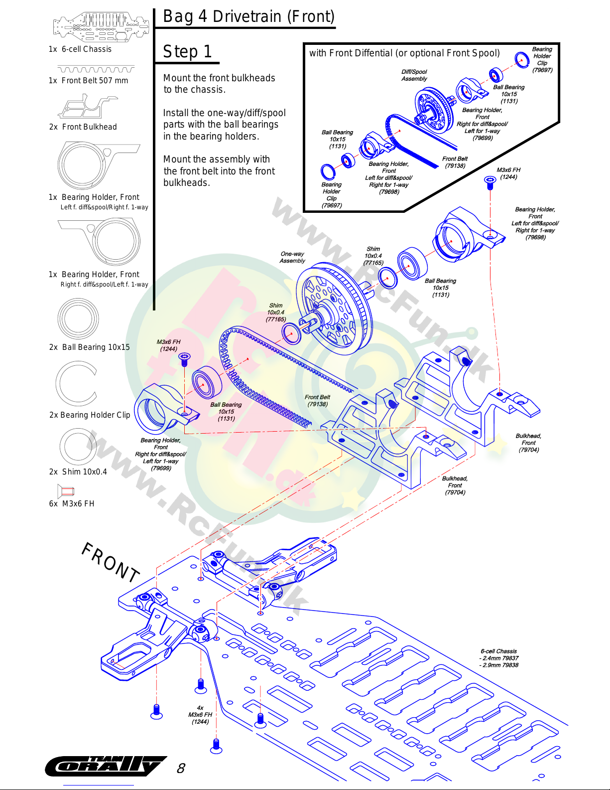
Mount the front bulkheads
to the chassis.
Install the one-way/diff/spool
parts with the ball bearings
in the bearing holders.
Mount the assembly with
the front belt into the front
bulkheads.
Step 1
FRO
N
T
2x Ball Bearing 10x15
1x Bearing Holder, Front
Left f. diff&spool/Right f. 1-way
1x Front Belt 507 mm
6x M3x6 FH
1x 6-cell Chassis
Bag 4 Drivetrain (Front)
with Front Diffential (or optional Front Spool)
1x Bearing Holder, Front
Right f. diff&spool/Left f. 1-way
2x Front Bulkhead
2x Shim 10x0.4
2x Bearing Ho lder Clip
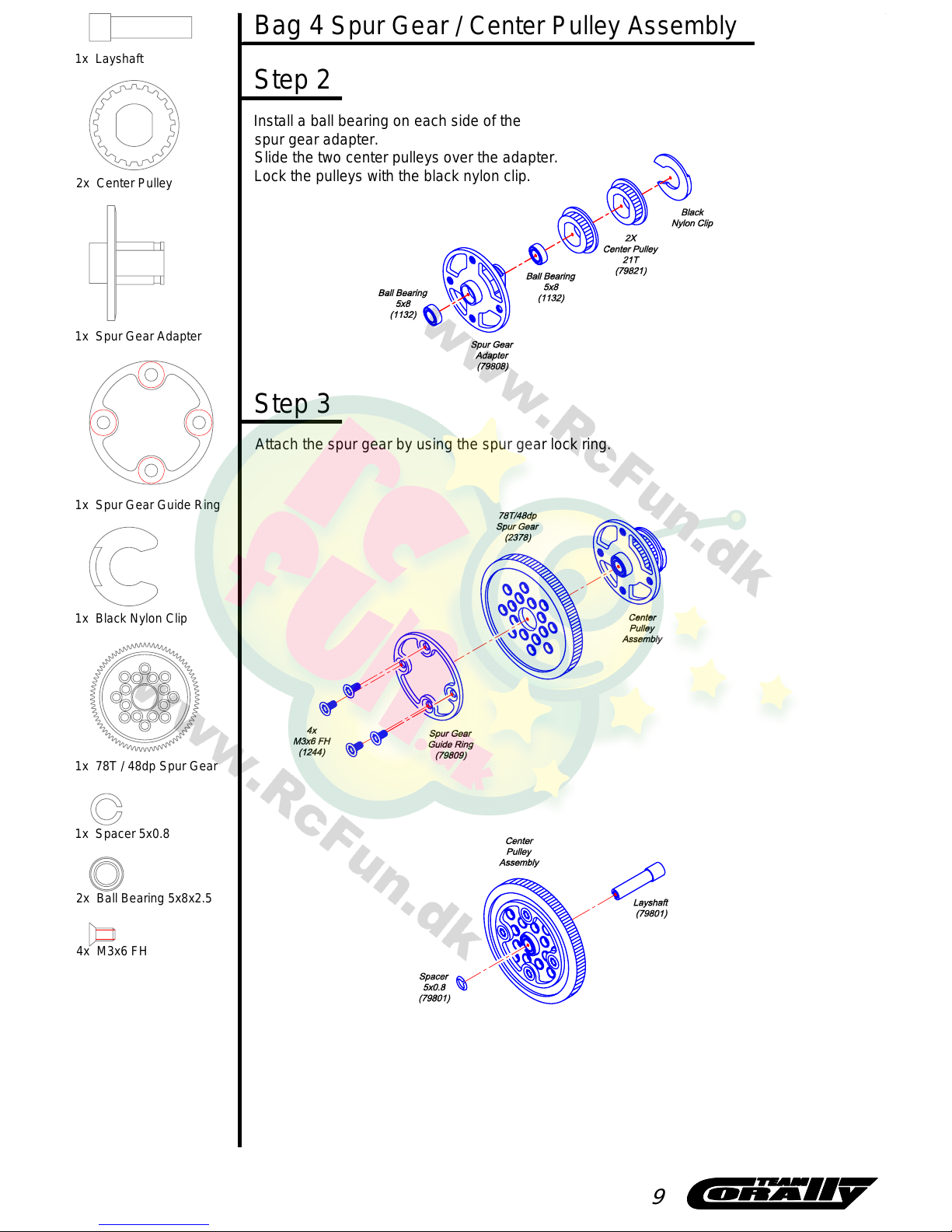
Spur Gear / Center Pulley AssemblyBag 4
1x Spur Gear Adapter
1x Layshaft
1x Spur Gear Guide Ring
2x Center Pulley
Step 2
Install a ball bearing on each side of the
spur gear adapter.
Slide the two center pulleys over the adapter.
Lock the pulleys with the black nylon clip.
4x M3x6 FH
2x Ball Bearing 5x8x2.5
Attach the spur gear by using the spur gear lock ring.
Step 3
1x 78T / 48dp Spur Gear
9
1x Spacer 5x0.8
1x Black Nylon Clip
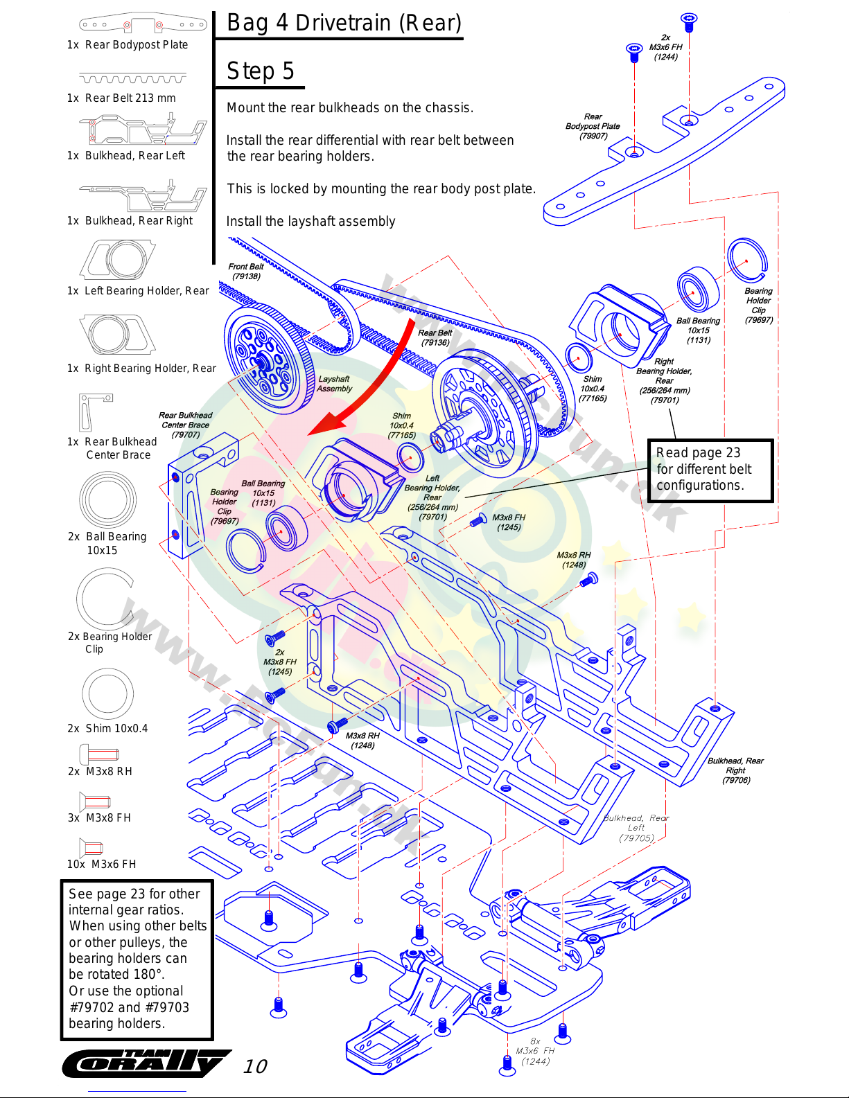
Step 5
Mount the rear bulkheads on the chassis.
Install the rear differential with rear belt between
the rear bearing holders.
This is locked by mounting the rear body post plate.
Install the layshaft assembly
1x Rear Bodypost Plate
2x Ball Bearing
10x15
10x M3x6 FH
2x M3x8 RH
Drivetrain (Rear)Bag 4
1
0
1x Rear Belt 213 mm
1x Bulkhead, Rear Left
1x Bulkhead, Rear Right
1x Left Bearing Holder, Rear
1x Right Bearing Holder, Rear
2x Bearing Holder
Clip
3x M3x8 FH
2x Shim 10x0.4
See page 23 for other
internal gear ratios.
When using other belts
or other pulleys, the
bearing holders can
be rotated 180°.
Or use the optional
#79702 and #79703
bearing holders.
1x Rear Bulkhead
Center Brace
Read page 23
for different belt
configurations.

Bag 5
Steering Lever
Chassis
1x Antenna Holder
7x M3x6 FH
2x Ball Bearing 5x8
4x Pivot Ball 4.3 mm
M3x2.5 mm
1x Steering Lever
1x Steering Lever Post
1x Topdeck
11
Screw the pivot balls on
the steering lever.
Build 3 turnbuckles as shown.
Snap them on the pivot balls.
After assembling the parts to the topdeck,
mount the topdeck under the bulkheads.
6x Ballcup
Turnbuckle long 38mm
(79273)
Turnbuckle short 21mm
(79270)
2x Turnbuckle 38 mm
1x Turnbuckle 21 mm
2x
1x

Step 1
Mount the pivot balls
for the camber links
to the shock tower.
Mount the front bumper.
Slide it between the
bulkheads and the
chassis plate.
Loosen the bulkheads
screws a couple of turns
to make it easier.
Then tighten the
screws again.
Step 3
3x M3 Nut
2x M3x6 FH
2x Pivot Ball 4.3mm
Front Camber Link
1x Front Bumper
1x Front Shock Tower
2x 3x6 Washer
Bag 5 Chassis (Front)
1
2
Mount the shock tower
assembly to the front
bulkheads.
Step 2
3x M3x8 FH

Mount the shock tower
assembly to the rear
bulkheads.
Step 1
Mount the pivot balls
for the camber links
to the shock tower.
1x Rear Shock Tower
Step 2
2x M3x6 FH
2x Pivot Ball 4.3mm
Rear Camber Link
2x M3 Nut
Chassis (Rear)Bag 5
2x 3x6 Washer
1
3

4x MIP CVD Axle
4x MIP CVD Bone
4x Driveshaft Cap
4x MIP CVD Coupling
2x C-hub Ball Screw
Step 2
Step 1
MIP CVD Assembly
FRO
N
T
R
E
A
R
L
R
8x Ball Bearing 5x9
1x C-hub 2-L (2° Left)
2x Steering Block
2x Rear Upright, Narrow 0°
Build 2 front steering block and 2 upright assemblies.
2x C-hub Screw
M
I
P
L
u
b
e
TM
TM
MIP CVD
MIP CVD
TM
MIP CVD
TM
TM
MIP CVD
TM
TM
TM
TM
TM
4x MIP CVD Cross Pin
M
I
P
T
h
r
e
a
d
l
o
c
k
(4 pieces)
Apply a little bit
of threadlock
to the setscrew.
Bag 6 Suspension 1 (Subassembly)
1x C-hub 2-R (2° Right)
2x MIP CVD SET
TM
#79180 containing:
#79180
4x MIP CVD M4 Lock Nut
TM
TM
2x MIP CVD Set Screw Driver
1
4
4x MIP CVD Set Screw
2x Pivot Ball 4.3 mm
M3x2.5 mm

Step 1
Mount the front steering block
assemblies to the wishbones
by using the outer hingepins.
Lock the hingepin with a set screw.
The hingepins can also be locked
with the e-clips.
2x M3x3 Set Screw
2x Outer Hingepin
2x Pivot Ball 4.3 mm
M3x7.5 mm
2x M3 Nut
4x E-clip
Suspension 1 (Front)Bag 6
1
5

Mount the rear upright
assemblies to the wishbones
by using the outer hingepins.
Lock the hingepin with a set screw.
The hingepins can also be locked
with the e-clips.
Step 1
2x Outer Hingepin
Suspension 1 (Rear)Bag 6
1
6
4x E-clip
2x M3x3 Set Screw

4x Large Delrin Spacer
4x Small Delrin Spacer
4x Spring Adjustment Nut
4x Spring Collar
4x Spring 17.0 lbs
8x E-clip
4x Spring Clip
4x Ball End
4x Shock Diaphragm
4x 13x1mm O-ring
4x Shock Cap
4x Piston Shaft
8x Silicone O-ring
4x Shock Body
4x Piston
4x Shock Top
Holding the shock straight up, fill
with shock oil to the top of the
body. Then slowly move the
shaft up and down several times
to allow air bubbles to escape
to the top.
Make sure all air bubbles escape
to the top then install shock
diaphragm, shock top and
aluminium shock cap.
Apply a few drops of
shock oil to lubricate
the O-rings.
S
i
l
i
c
o
n
e
S
h
o
c
k
O
i
l
(
8
0
1
2
0
)
S
i
l
i
c
o
n
e
S
h
o
c
k
O
i
l
(
8
0
1
2
0
)
Suspension 2 (Shocks) - PRE-ASSEMBLED
Use plier to hold
shaft, but do not
damage the shaft.
Grip it close to
thread.
Build 4 identical Shock Absorbers (79220).
Build them very carefully.
Bag 7
1
7
NOTE: NO OIL in pre-assembled shocks

Step 1
2x Turnbuckle 33mm
4x Ball Cup
Front Turnbuckle 33mm
(79272)
Snap all links in place with a plier.
Snap the aluminium balls in the shocks and
mount them to the shock tower and wishbones.
2x Pivot Ball 5.8 mm Short
Bag 7 Suspension 2 (Front)
Step 2
1
8
2x
Assemble 2 Turnbuckles as shown.
2x M3x8 RH
2x Pivot Ball 5.8 mm

Step 1
Step 2
Turnbuckle 28mm
(79271)
2x Turnbuckle 28mm
4x Ball Cup
Assemble 2 Turnbuckles as shown.
2x
Snap the rear turnbuckles in place
with a plier.
Snap the aluminium balls in the shocks
and mount them to the shock tower
and wishbones.
2x Pivot Ball 5.8 mm Long
Suspension 2 (Rear)Bag 7
1
9
2x Pivot Ball 5.8 mm
2x M3x8 RH

2x Battery Strap Post
3x M3x8 RH
2x M3x10 FH
4x Body Post
3x M3x6 FH
4x Wheel Hex Adapter
4x Pin Ø9.5x2
4x M2x5
Finals (Wheelhex & Bodyposts)Bag 8
1x O-ring 2x1
1x Belt Guide Post
1x Belt Guide Tower
1x Belt Guide
2x Ball Bearing 4x7x2.5F
NOTE:
Do not screw the M2x5 screws in the hexagons too
tight. They are meant to eliminate play and to keep
the hexagons in place when pulling off the wheels.

Use a medium servo saver (10201)
(not included) to protect your servo.
The servo link length is just an
indication. The servo saver must
stand up straight when all the
settings of the car are in the
neutral position.
- 4x Tires on wheels
- 1x Servo with Servo-Saver
2x M3x8 RH
2x Servo Post
2x Alu Washer Ø3.2x7
1x Foam Bumper
2x Body Post Nut
Not Included:
Finals (Wheels & Foambumper)Bag 8
2x M3x6 FH
1x Bumper Plate
It is recommended to drill
or ream the servo saver
up to Ø4 mm to allow
the use of a M3 insert

Install the electronics and the body post nuts.
Use double-sided tape
for your receiver and
electronic speed
controller.
1x Battery Strap
8x Body Post Nut
2x M3x8 FH
Not Included:
- Electronic Speed Control
- Receiver
- Electric Motor
2x M3x6 FH
2x O-ring 2x1
Finals (Electronics)Bag 8
- Pinion Gear
- Double-sided Tape
Mount the servo with servo saver
to the chassis.
Then snap the turnbuckle 21mm
to the pivot balls on the steering
lever and the servo saver.
- Sub-C Battery-pack (5 or 6-cell)
2x M3x8 RH

Radio adjustments
- Turn the transmitter on.
- Make sure the motor is disconnected.
- Connect your battery pack.
- Turn the power switch on.
- Make sure the wheels move in the right
direction. If you turn the steering control
to the left, the wheels should move to the
left. If you turn the steering control to the
right, the wheels should mo v e to the right.
- Adjust the servo link so your servo saver
is rising upwards.
- Using the two steering turnbuckles, adju s t
the front wheels so they are pointed
straight up.
- Adjust the Electronic Speed Controller
according to your speed control
manual. Turn off the power switch.
- Connect the motor. Be sure that the wheels
do not touch anything. Turn on the power
switch and check the settings of the ESC and
steering. Turn t he power switch off again.
- The transmitter is always the
FIRST TO BE TURNED ON and
THE LAST TO BE TURNED OFF.
Gear Ratio Charts
- Standard 507 mm / 213 mm belts with 42T / 21T pulleys
- Optional 510 mm* / 210 mm* belts with 42T / 21T pulleys
- Optional 507 mm / 186 mm* belts with 42T / 17T pulleys (turn Bearing holders 180° for 256 mm belt configuration)
- Optional 510 mm / 186 mm* belts with 42T / 18T pulleys (turn Bearing holders 180° for 256 mm belt configuration)
- Optional 480 mm / 210 mm* belts with 36T / 17T pulleys
- Optional 507 mm / 186 mm* belts with 36T / 18T pulleys
- Optional 507 mm / 186 mm* belts with 36T / 21T pulleys (use Bearing holders #79702 and #79703 for 260 mm belt configuration)
* optional belts available from mid 2007
19
18
22
23
21
20
24
26
25
27
30
29
28
32
31
23
33
36
37
35
34
32
31
30
29
28
27
26
25
24
39
38
40
48dp 64dp78T 98T 100T 104T
8.67
5.57
5.03
4.88
5.20
5.38
5.78
6.00
6.24
6.50
6.78
7.09
7.42
7.80
8.21
8.52
5.94
4.90
5.03
5.16
5.30
5.44
5.60
5.76
6.13
6.32
6.53
6.76
7.00
7.26
7.74
7.84
8.17
8.70
6.06
5.88
5.71
5.56
5.40
5.26
5.13
5.00
8.33
8.00
7.70
7.41
7.14
6.90
6.67
6.45
6.25
9.04
6.30
5.20
5.33
5.47
5.62
5.78
5.94
6.11
6.50
6.71
6.93
7.17
7.43
7.70
8.00
8.32
8.67
#2378 #24098 #24100 #24104
17
9.18
22
8.91 9.09 9.45
5.85
39
5.97 6.21
5.71
40
5.83 5.98
48dp
24
31
32
28
29
30
27
25
26
23
19
18
22
21
20
17
29
8.368.037.877.57
6.92
6.02
6.17
6.34
6.52
6.72
7.14
7.36
7.61
33
36
37
35
34
32
31
30
38
7.06
6.85
6.66
6.47
6.30
6.13
7.67
7.52
7.28
8.08
7.82
7.57
7.13
6.92
6.73
6.55
6.38
7.25
7.27
6.99
6.73
6.27
6.06
5.68
5.86
6.40
28
10.87
#24104
10.09
9.69
9.32
8.97
8.65
10.53
104T
10.59
#24100
8.32
8.63
8.96
9.32
9.71
10.13
100T
10.37
22
#24098
9.39
9.14
8.78
8.46
8.16
9.93
98T64dp
24
25
26
27
23
78T
10.09
7.90
8.26
8.65
9.09
9.56
#2378
10.69
6.20
39
6.33 6.59
6.42
6.05
40
6.18
11.67
10.70
10.27
9.88
9.51
9.17
11.17
8.56
8.29
8.03
7.55
7.33
7.14
6.94
6.76
7.78
8.86
#24104
104T
24
29
8.528.358.03
31
32
28
29
30
27
25
26
7.33
6.37
6.54
6.72
6.52
7.12
7.56
7.81
8.07
33
36
37
35
34
32
31
30
38
7.49
7.26
7.06
6.86
6.68
6.50
8.23
7.96
7.72
7.71
7.41
6.88
6.64
6.42
5.83
6.21
6.64
48dp
23
19
18
22
21
20
17
28
11.22
#24100
8.82
9.15
9.50
9.88
10.29
10.73
100T
11.00
22
#24098
10.08
9.68
9.31
8.96
8.64
10.52
98T64dp
24
25
26
27
23
78T
10.70
8.37
8.26
9.17
9.63
10.14
#2378
11.33
17 22
7.84
22
7.62 7.77 8.08
17
27
30
29
28
32
31
20
21
22
18
19
23
26
25
24
27 32
4.94 5.565.34
32
5.24
4.76
4.30
4.17
4.45
4.50
5.39
4.68
4.81
4.94
5.08
5.23
4.50
4.62
4.75
4.88
5.34
5.18
38
34
35
37
36
33
4.93
4.79
4.66
4.53
4.41
5.08
4.45
4.27
40
4.19
4.564.38
39
4.29
30
29
28
32
31
38
34
35
37
36
33
40
39
7.02
6.67
6.35
6.06
5.80
7.41
23
27
26
25
24
7.29
5.99
6.20
6.44
6.70
6.98
7.29
6.98
6.70
6.45
6.20
6.11
7.73
6.35
6.59
6.84
7.14
7.41
28
5.13
5.33
5.74
5.93
5.52
5.70
30
31
5.59
5.40
5.56 5.78 5.89 6.13
29
20
21
22
18
19
23
23
27
26
25
24
28
26
25 30
31
24 29
48dp
#2378
78T 64dp 98T
#24098
100T
#24100
104T
#24104 #2378
78T48dp
#24104
64dp 98T
#24098
100T
#24100
104T
17
9.73 9.649.44
22
10.02
27
6.12 6.49
32
6.63 6.89
6.48
6.30
6.12
5.96
5.80
6.68
5.51
5.65
31
32
28
29
30
5.70
5.51
5.17
5.33
5.90 6.32
5.46
5.62
5.77
5.94
6.11
33
36
37
35
34
38
6.42
6.24
6.06
5.89
5.73
5.58
5.19
40
5.30
5.33
39
5.44
9.19
8.82
8.48
8.16
7.87
9.59
7.35
7.11
7.60
23
19
18
22
21
20
9.19
7.19
7.52
7.87
8.27
8.70
28
7.57
7.31
8.15
8.48
8.83
9.22
8.66
8.31
7.99
7.69
7.42
9.03
24
25
26
27
23
25
26
6.61
6.36 6.70
6.93
31
30
7.07
6.84
24
6.89
29
7.317.16
#24104
104T48dp 78T
#2378
100T
#24098
98T64dp
#24100
42T / 21T Pulleys (standard) 42T / 18T Pulleys (optional) 42T / 17T Pulleys (optional)
36T / 21T Pulleys (optional) 36T / 18T Pulleys (optional) 36T / 17T Pulleys (optional)
8.91 9.09 9.45
6.506.256.13
6.30
5.47
5.62
5.78
5.94
6.11
5.26
5.40
5.56
5.71
5.88
6.06
5.76
5.60
5.44
5.30
5.16
5.94
5.205.004.90
5.335.135.03
8.52
7.00
7.26
7.74
7.84
8.17
8.70
8.33
8.00
7.70
7.41
7.14
9.04
7.43
7.70
8.00
8.32
8.67
6.71
6.93
6.45
6.676.53
6.32
6.76 6.90 7.17
9.18
5.78
5.57
5.03
4.88
5.20
5.38
8.21
7.80
7.42
7.09
6.78
8.67
6.00
6.24
6.50
The RDX Phi has several internal ratio options.
- 2,00 : 1
- 2,00 : 1
- 2,47 : 1
- 2,33 : 1
- 2,11 : 1
- 2,00 : 1
- 1,71 : 1

79912 Anti-roll bar set 1.3 mm, Silver - Rear
79913 Anti-roll bar set 1.3 mm, Silver - Front
79914 Anti-roll bar set 1.6 mm, Brass - Rear
79915 Anti-roll bar set 1.6 mm, Brass - Front
79916 Anti-roll bar set 1.9 mm, Black - Rear
79917 Anti-roll bar set 1.9 mm, Black - Front
79922 Anti-roll bar wire 1.3 mm, Silver - Rear
79923 Anti-roll bar wire 1.3 mm, Silver - Front
79924 Anti-roll bar wire 1.6 mm, Brass - Rear
79925 Anti-roll bar wire 1.6 mm, Brass - Front
79926 Anti-roll bar wire 1.9 mm, Black - Rear
79927 Anti-roll bar wire 1.9 mm, Black - Front
Anti-roll bar clamps:
Use the big slot for Black 1.9mm Anti-roll Bar and the
small slot for Silver 1.3mm Anti-roll Bar. When using
the Brass 1.6mm Anti-roll Bar, sand 0.3mm off the
bottom of the clamp so the 1.9mm slot will fit the
1.6mm Anti-roll Bar wire.
Anti-roll bar mounting instructions (option part)
4x M3x12 Set Screw
4x Pivot Ball 5.8mmm
2x M3x15 RH
4x M3x8 FH
1x Anti-roll Bar Rear
4x Anti-roll Bar Clamp
2x Pivot Ball 5.8 mm Short
1x Anti-roll Bar Front
2
4
2x Pivot Ball 5.8 mm
4x M3x3 Set Screw
4x Ball End 5.8mm

Race adjustments:
FRONT
+
+
Toe-out
Toe-in
Toe-in
Toe-out
Toe-out:
Increases turn-in steering a lot.
But can make the car very nervous on the straight.
More than 1° of front toe-out make the front even more
nervous, so it's better not to use more than 1° toe-out.
Toe-in:
Stabilizes the car on the straight, and coming out of
the corners.
It smoothes out the steering response, making the car
easier to drive.
It can make the car turn in a little more in the middle and
exit part of a corner.
Toe-in:
This is one of the most sensitive adjustments! One degree goes
a long way. Stabilizes the car greatly. It makes the rear end
"stick". The more toe-in you use, the more the rear of the car
sticks. This becomes especially apparent going in and coming
out of the corners.
But more toe-in make more difference between sticking and
breaking loose. Large amount of toe-in (2.5°... 3°) scrub off
a little speed on the straights.
Toe-out:
Rear toe-out is never used. It makes the rear of the car very
unstable.
-
-
Toe-in
Toe-out
Toe-in
Toe-out
Your RDX Phi Touring Car comes with many possible geometry adjustments, shock adjustments,
camber changes, etc. The standard setup in this manual is a good starting point to begin
with. For optimising your car's performance, improvements can be made with the following
tuning tips. Always make one step at a time, and see if there are any improvements or the
performance is getting worse. On www.corally.com you can download the latest setup
sheets from Team Corally to help you find a good setup.
Front toe-in / toe-out:
Setting toe-in of the front wishbones in the center of the car will make the suspension work
better on bumpy conditions. Never use toe-out.
Adjust for neutral feeling 0° toe. A slight amount of toe-out will increase the turn-in of the car
but too much of it will make the car difficult to drive.
[min. = -1 / max. = +1]
Rear toe-in:
Toe-in is set standard on 2° in the rear with the coupler clamps. To increase toe-in in the rear,
use the rings of 0.4mm for 0.5° settings and 0.8mm for 1° settings.
[min. 0 / max. 3]
2
5
-

Camber:
Camber is best set when the contact patches of the tires are is always as big as possible. So with a
stiff suspension and firm tires you'll need less camber than with soft suspension or tires with big,
flexible sidewalls. If the tire wear evenly across their contact patches, the camber is about right. Whe
using camber on the front in combination with caster blocks something must be kept in mind. Caster
will cause camber in the front when steering and the front will lift up.
[min. 0 / max. 2]
Camber Link Locations:
The RDX Phi has a couple of camber-link locations. We recommend to start off by mounting the
camber links in 1 of the lower positions on the shocktower. This will give more camber-change
while cornering, thus stability. The longer or higher the link, the more traction and less stability. The
shorter or lower the link, the less traction and greater stability.
Long Link: A long link gives a lot of body roll in turns. It feels as if the body is willing to keep on
rolling until it can't, but the springs prevent it from rolling any further.
The car has more grip in corners, especially in the middle part. But if there already is a lot of traction,
long camber links can slow down in turns.
Short Link: A short link will make the chassis roll less. Its tendency to roll drops as it rolls.
It feels as if the car generates a little less grip.
More Parallel Link: A parallel link gives a little more roll than an angled one. It feels smooth,
and consistant as the body rolls in turns.
Angled Link: An angled link makes the car feel as if it has a tendency to center itself (level, no roll
)
other than through the spring or anti-roll bar. It will give more initial grip, steering into corners.
It makes it very easy to "throw" the car. The body rolls a little less than with parallel links. It's possibl
e
to use softer springs and a softer damping than with parallel links, without destabilising the car.
Always keep an eye on the balance of the car; large differences in roll-center front versus rear will
make the car feel less consistant!
Inner Hingepin Locations:
It is possible to mount the wishbones on different heights to the bulkheads. This will change the
roll-center of the car.
Low mounting: The roll-center becomes lower, which generates more chassis-roll into the
corner.
Higher mounting: The roll-center becomes higher, which generates less chassis-roll.
Car changes quicker from direction, but less grip will be generated. Feels very stable.
REAR
5 Positions6 Positions
FRONT
3 Positions
REARFRONT
2
6

FRONT
Position:
0°
Position:
0.8°
Front Caster:
Caster can be very important to the handling of the car. Adding or removing caster can transform
the steering balance of a car. The total of Caster is degrees Kick-up + degrees Caster C-hub.
More Caster: Will give stability, especially at high speeds. More Caster generally suits large
high-speed open tracks.
Less Caster: Will increase steering drastically. Steering feels more direct, so the car turns tighter
and faster. Small amounts of caster are suitable for tight tracks.
These settings can be arranged with the optional C-hubs and the inner hingepin settings.
[min. 0 / 2 / 4 / max. 6]
Front Kick-up and anti-dive:
Refers to the angle in which the front suspension is mounted in relation to horizontal when looked fro
the side of car. Kick-up and anti-dive are adjusted by changing the angle of the front wishbones,
which can be done by the aluminium hingepin adjustment blocks. The setting of 0° kick-up will have
more aggressive steering feeling but will not absorb bumps well. The setting of 1.6° kick-up will work
better in most conditions, especially in bumpy conditions. The anti-dive setting of 1.6° will give a very
aggressive steering feeling and will improve the front braking traction by entering corners. For less
agressive steering feeling a setting of 0.8° is also possible. It is necessary to use the optional couple
r
clamps (#79709) for the left and (#79710) for the right. When using anti-dive a differential must b
e
used in the front. Use at least 2° caster C-hubs. Anti-dive will not work on bumpy conditions.
Rear anti-squat:
Describes the angle at which the rear suspension is mounted when looked sideways at the car.
Generally more anti-squat make the car more sensitive by throttle input. The car has more steering
while braking (when diff is used), and also a little more powering out of the corners. Less anti-squat
gives more side-bite, on-power and while braking. It feels easier to drive in low-grip situations.
Wheelbase adjustment:
1.6°
high (#79709 and #79710 must be used)low
FRONT
Position: Position:
Position:
high/low
0°
high/low
Position:
FRONT
lowhigh
Adjustment shims Adjustment shims
Kick-up Anti-dive (only use 2°,3°,4° or 6° caster bloc
k
2
7
1.6°
0.8°
1.6°
low high
high
high low (#79709 and #79710 must be used)
low
high/lowhigh/low

NEUTRAL STEERING
Adjust the wheelbase by moving the white inner hingepin shims. A short wheelbase makes the car
feel good in tight turns. Use a short wheelbase on very small and tight tracks. A longer wheelbase
makes the car feel a lot more stable, and better in wide, high-speed turns. Use a longer wheelbase
on wide open tracks. Moving the shims to the front of the front wishbones will shorten the wheelbase
and decrease rear traction and greater stability. Moving the shims to the rear of the front wishbones
will lengthen wheelbase and increase rear traction. Moving the shims to the front of the rear wishbon
e
will lengthen the wheelbase and decrease rear traction and greater stability. Moving the shims to the
rear of the rear wishbones will shorten the wheelbase and increase rear traction.
Ackermann:
This is a term describing the effect of the inner front wheel turning tighter than the outside front whee
The perfect angle (no slip in theory) between the two front tires is called "the Ackermann angle".
The angle can be varied by adjusting the steering linkages. The Ackermann setup works well in mos
t
conditions and will provide a very smooth, predictable steering.
Shock Springs:
Try to keep your car level during acceleration, deceleration and cornering.
Stiffer springs make the car feel more responsive, more direct. The car reacts faster to driver input.
Stiff springs are suited for tight, high-traction tracks, which aren't too bumpy. Usually, when you stiffe
n
the whole car, you lose a small amount of steering.
Softer springs are better for bumpy and very large and open tracks. They can also make the car feel
as sluggish and slow.
Stiffer Front:
The car has less front traction, and less steering. It's harder to get the car to turn, the turn radius is
bigger and the car has a lot less steering exiting corners. On very high-grip tracks, if the track itself
feels tacky or sticky, very stiff springs are the way to go.
Softer Front:
The car has more steering, especially in the middle part and the exit of the corner.
Front springs that are too soft can make the car hook and spin.
Stiffer Rear:
The car has more steering, in the middle and exit of the turn. This is especially apparent
in long, high-speed corners. But rear traction is reduced.
Softer rear:
The car has generally more rear traction, in turns as well through bumpy sections and
while accelerating.
2
8
L
-
3
0
°
L
-
3
0
°
R
-
21
°
R
-
2
2
°
MORE NEUTRAL STEERING

Damping:
Thicker oil (heavier damping) makes the car more stable, and makes it handle more smoothly.
If damping is too heavy, traction could be lost in bumpy sections. The car will also change direction
slower. Soft damping makes the car react quicker. Damping should always be adapted to the
spring ratio; the suspension should never feel to "springy" or too slow.
Heavier Front or Softer Rear: The turn radius is wider, but smoother. The car doesn't hook up
suddenly. The car is easier to drive, and high-speed steering feels very nice. Easy to drive.
Softer Front or Heavier Rear: The steering reacts quicker. More and better low-speed steering
Shock Pistons:
The assumption is made that if pistons are changed, the viscosity of oil is also adapted, to give the
same static feel. (Same low-speed damping)
Smaller holes (#79223) means more "pack". Pack means the damping gets very stiff, or almost
locks up, over sharp bumps. Small holes are good for smooth tracks.
Bigger holes (#79224) mean less pack. The point at which the damping gets stiff (where the
shock "packs up") occurs a lot later, at higher shock shaft speeds. Big holes are very good for bump
y
tracks. The car is more stable and has more traction in the bumpy sections. It won't be thrown up ov
e
sharp bumps, the suspension will soak them up a lot better.
Ride Height:
This describes the height of the chassis in relation to the surface sitting on. This adjustment must
be made with the chassis ready-to-run but with no body. By turning the spring adjustment nut the
chassis can be raised or lowered. Start with about 6mm clearance between the chassis and ground.
Try using a slightly lower ride height for high traction conditions as carpet racing. Do not use a ride
height lower than 4mm.
Higher: The car feels better in bumpy sections. It can feel tippy, or even flip over in high-grip
conditions.
Lower: The car feels more direct, and it can potentially corner a bit faster. It's also harder
to flip the car over. Lowering one end of the car, or putting the other end higher up, gives a little
more grip at the lowest end, but try to avoid big differences in ride height between the front and the
rear.
Anti-Roll Bars:
Before using anti-roll bars first try to play with the droop settings. Anti-roll bars can be used to stabiliz
a car from excessive roll (which occurs when your car leans through the turns by centrifugal force).
Anti-roll bars are generally used on smooth, high traction track conditions. If the conditions are very
bumpy, then anti-roll bars are probably not necessary. If you are driving on a high traction surface an
d
your car wants to oversteer, then use the optional #79913 (soft), #79915 (medium) anti-roll bar or
#79917 (hard) on the front only. This will decrease the front chassis roll and decrease steering
throughout the corner. This has the feeling of increasing rear traction. If your car is understeering,
then try the optional #79912 (soft), #79914 (medium) anti-roll bar or #79916 (hard) anti-roll bar
on the rear only. The rear anti-roll bar will decrease rear chassis roll and decrease rear traction (this
has the feeling of increasing steering).
Downstops (droop-setting):
When the Wishbones have a lot of droop the chassis is free to roll in turns. The center of gravity
of the car won't change much. Chassis rolls around its roll-center. But if the wishbones almost have
no droop the chassis will be pulled down as it rolls. It cannot roll anymore around its roll-center,
because the chassis will become one-piece with the wishbone as it rolls. Then the center of gravity
will become lower.
2
9

Front:
- Less droop makes the car smoother in the middle of a corner and gives more steering under
acceleration. Sometimes too little droop makes a car difficult to accelerate out from corners.
- More droop gives more steering response in the middle of a corner and makes the car push on
throttle.
Rear:
- Less droop makes the rear more stable to the corner and gives less grip in the middle and out of
the corner.
Less droop will heat up tires more.
- More droop reduces rear grip into the corner, but rear tires stay cooler and the car works more
stable through your heat.
Before using anti-roll bars, the droop-setting is a better option first to play with. The wishbones are
already prepared for using downstops. See the instructions on page 7 for installing the M3x12
set screws which are required for adjusting the droop. The adjustment of left and right should be the
same. But don't use your downstops for lowering your chassis, because this isn't the way to do so.
This must be done by the spring adjustment of your dampers.
Front Drive:
- Ball Differential (#79690) can be adjusted for tightness (and slippage), so it makes them very
versatile. By adjusting the front diff a little tighter, some more understeer will be experienced. But
there will be a little more steering and traction exiting the corner. It feels more stable. When tighten
the rear diff, the rear of the car will become easier to break loose. But adjusting the diffs is not really
a good solution to solve the problem of under/oversteer balance.
- One-way (#79667) contains two one-way bearings; one for each wheel. It acts like a diff in only
the forward direction. The front wheels can only turn faster than the rear wheels, but not slower. Left
and right wheel can rotate independantly from each other, when power off entering a corner. This will
give slightly more steering, so the corner can be taken faster. With a one-way front diff there will be
no front braking, no differential action off power, high cornering speed, and excellent acceleration out
of the corner. On really high-grip, open tracks with smooth, flowing high speed corners it is a one to
have thing. So it comes standard in this kit.
- Spool (#79655) is like a fully locked diff but has no moving parts. It's super-solid with no
adjustments. Because there's no differential action at all, a lot of speed is scrubbed off in corners.
A spool at the front will make the car very hard to turn in. But gives stability under acceleration and
deceleration. A spool at the rear will give a lot of steering.
Shock position:
The RDX Phi allows 3 front and 4 rear top fixing positions for the shock absorbers.
More Inclined: Has a more progressive smoother feel. More lateral grip. Having all shocks incline
d
makes the car very easy to drive, and it feels like the car has more grip, but it's not always fast...
Less Inclined (more vertical): More direct feel. Less lateral grip. (site-bite)
Front more inclined than rear: Ste ering fee ls very smooth. A little more mid -co rner steering.
Mounting the rear shocks very much upright can result in the rear end feeling unpredictable. It also
makes the rear end jitter in turns.
Rear more inclined than front: Feels agressive turning in, but for most of time the car has
a little less steering. The car has a lot of side traction in the rear, and the turn radius isn't very tight.
2 Wishbone Settings 3 Wishbone Settings
FRONT VIEW
Top Settings
REAR VIEW
Top Settings
30

Wishbones:
I
t's possible to use different kind of Wishbones:
Medium 5 : Front (#79040) - Rear (#79050)
Hard 35 : Front (#79060) - Rear (#79070)
X-Hard 80 : Front (#79080) - Short (#79090)
Duraluminium : Front and Rear (#79108)
Softer Wishbones can add a little more grip because they flex a bit more.
Harder Wishbones can be used if there is plenty of traction but suspension setup will be more
important. Suspension setup feels better and more consistent.
Tires & Inserts:
All these possibilities cannot be fully exploited if the car does not run on quality wheels. Tires and
inserts are two of the most influential changes you can make to your car. The Corally RDX Phi kit
comes without tires and wheels. There's a variety of wheels, inserts and tires available. Which one
is the best for you depends on the different weather or track conditions as well as local rules when
competing in championships.
Tire Additives:
Corally tire additives come in a large can (150ml) complete with brush for easy application.
TC-1: Classic formula for use on foam tires on carpet tracks.
TC-2: JACK THE GRIPPER is odorless and EFRA legal. This is the most populair choice for use on
rubber and foam tires on any surface.
TC-3: Formulated for outdoor use.
TC-4: CARPET JACK is upgraded Jack The Gripper specially formulated to provide maximum grip
for rubber tires on carpet tracks - odorless.
- TC-1 (#13788) Formulated for foam tires on carpet
- TC-2 (#13779) Jack the Gripper (Minimum Odor)
- TC-3 (#13789) Unpleasant Smell, Maximum Traction
- TC-4 (#13790) Carpet Jack
Setup Sheet:
There's a setup sheet included in this manual. Set up your RDX Phi with the standard settings at right
then deviate from them in response to your track conditions and driving style, as noted below.
For best result, make only one setup change at a time, testing it before making another change. Mak
e
a copy of the setup sheet included in this manual to help keep track of your changes. Before make
any changes to standard setting, make sure you can get around the track without crashing. None of
your setup changes will work if you cannot stay on the track. Your goal is consistent laptimes.
Inconsistent lap times may indicate poor control. When you have consistent lap times, then make
changes to your car. If the change results in a faster lap, then mark the change in your setup sheet.
If performance is worse, then revert to previous setup and try another change. Fill out your setup
sheet thoroughly when you are satisfied with it and file it away. It can be a practical guide for future
track lay-outs and conditions you encounter. Always keep in mind that your car stays in balance. Too
much difference in front and rear setup can make the car feel unpredictable.
We at Team Corally wish you best luck and see you at the track!
Contact:
http://www.corally.com
e-mail: team@corally.com
Fax: (+31) 78 621 26 89
Corally R/C BV
Ploegstraat 49
3319 LG Dordrecht
Holland
31

T
T /Spur / Pinion
Finish
Race Comments
Traction
Temp.
Main
Track Conditions
Radio
Body
Motor
Surface
Servo
Lead Weights
Wing
Motor setup
g
Qual. Pos.
Weight balance
ESC
Re
a
Oil
Piston
Tires
Others
Rear
Toe-in
Camber
Ride Height
Anti-squat
Anti-roll bar
mm
Downstops
Driver:
Track / City:
Event:
Oil
Piston
Front
Ride Height
Camber
Toe-out
Caster
mm
Anti-roll bar
Downstops
S E T U P S H E E T
WT
Date:
Upright
Front width
Rear width
mm
mm
toe-in
WT
Front
HIGH PERFORMANCE 1:10 ELECTRIC TOURIN G CAR
Spring
Spring
lbs
lbs
Time
Laps
Wishbone
Wheelbase
Wishbone
Front drive
Front pulley
Steering
Shock tower
Steering block
Coupler clamp
Clamp shims
F Coupler
F coupler shims
R Coupler
R coupler shims
Rebound
Wheelbase
Center pulley
Rear pulley
F Coupler
R Coupler
R coupler shims
F coupler shims
Clamp shims
Coupler clamp
Rebound
Shock tower
Tire additive
Notes
T
T
Coupler
clamp
Coupler
clamp
FR
FR
 Loading...