

Page 1
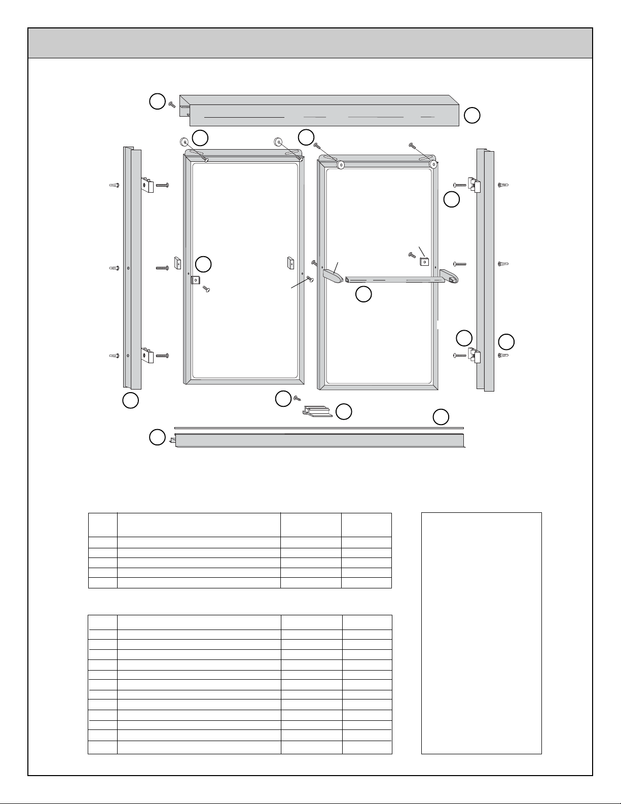
H901
PAN HEAD
SELF DRILLING
SCREW
O
HA16
PULL
HANDLE
H342
F
ROLLER
HBAH
TOWEL BAR
L
BRACKET KIT
21Y1
H430
K
TRUSS HEAD SCREW
HA14
TOWEL
BAR
BRACKET
HA12
PULL/STOP
H
H480
PAN
HEAD
SCREW
C
A950
HEADER
H479
PAN HEAD
SCREW
H901
O
OUTSIDE OF SHOWER
A947
JAMB
B
A925
SILL
H810
FLAT HEAD
SCREW
PAN HEAD SELF
DRILLING SCREW
A
FRAME PACKAGE
KEY
DESCRIPTION PART
A SILL A925 1
B JAMB A947 2
C HEADER A950 1
D TOWEL BAR A712 2
J VINYL TRACK GUIDE V145 1
HARDWARE BAG PARTS
L TOWEL BAR/PULL HANDLE KIT HBAH 1
F ROLLER H342 4
K 8-32 X 3/8 TRUSS HEAD SCREW H430 4
G GUIDE HA21 1
H 8A X 1 1/4 PAN HEAD SCREW H480 6
I BUMPER HB01 4
M ANCHOR H002 6
O 8A X 3/8 PAN HD SELF DRILLING SCR H901 3
8A X 1 PAN HEAD SCREW H479 2
PULL/STOP HA12 2
PULL HANDLE HA16 2
TOWEL BAR BRACK ET HA14 2
8A X 1 1/4 FLAT HEAD SCREW H810 2
G
A712
D
TOWEL BAR
V494
GUIDE
QTY
HB01
BUMPER
I
V145
J
VINYL TRACK GUIDE
H002
ANCHOR
M
TOOLS NEEDED
1/8" Drill Bit
3/16" Drill Bit
(3/16" Masonry Bit for
Ceramic Tile)
Scratch Awl
Measuring Tape
Hacksaw
Phillips Screw Driver
Caulking Compound
File
Drill
Level
Masking Tape
21Y1 (BYMT) 8/01
Page 2
INSTALLATION INSTRUCTIONS
Before starting installation of your new enclosure, carefully read all
instructions and lay out parts to become familiar with their identity.
USE OF ANCHORS
Anchors are furnished with every enclosure. However, the use of anchors is not recommended when attaching your enclosure to
a fiberglass unit or wall surrounds with board reinforced mounting areas. Mounting holes in this case should be drilled with a
1/8" drill bit.
Mounting of this unit on tile requires the use of anchors. Special care must be taken not to crack the tile. Before drilling holes in
the tile, lightly chip glazed surface of tile at the desired locations. Drill holes using a 3/16" masonry drill bit. Insert anchors into the
holes making certain that ring on large end of anchor meets the surface of the tile.
CLEANING
Cleaning and care of your enclosure is important to its lasting beauty. We suggest using a nonabrasive liquid cleaner.
Never use scouring powder or pads.
SEALING
The use of a caulking compound can assure a water-tight seal when applied along outside edge of the enclosure where metal and
bath meet. If desired, caulk inside of enclosure where jambs meet walls.
Do not try to cut the mirrors or glass used in this enclosure.
Tempered glass and mirrors will disintegrate if cut.
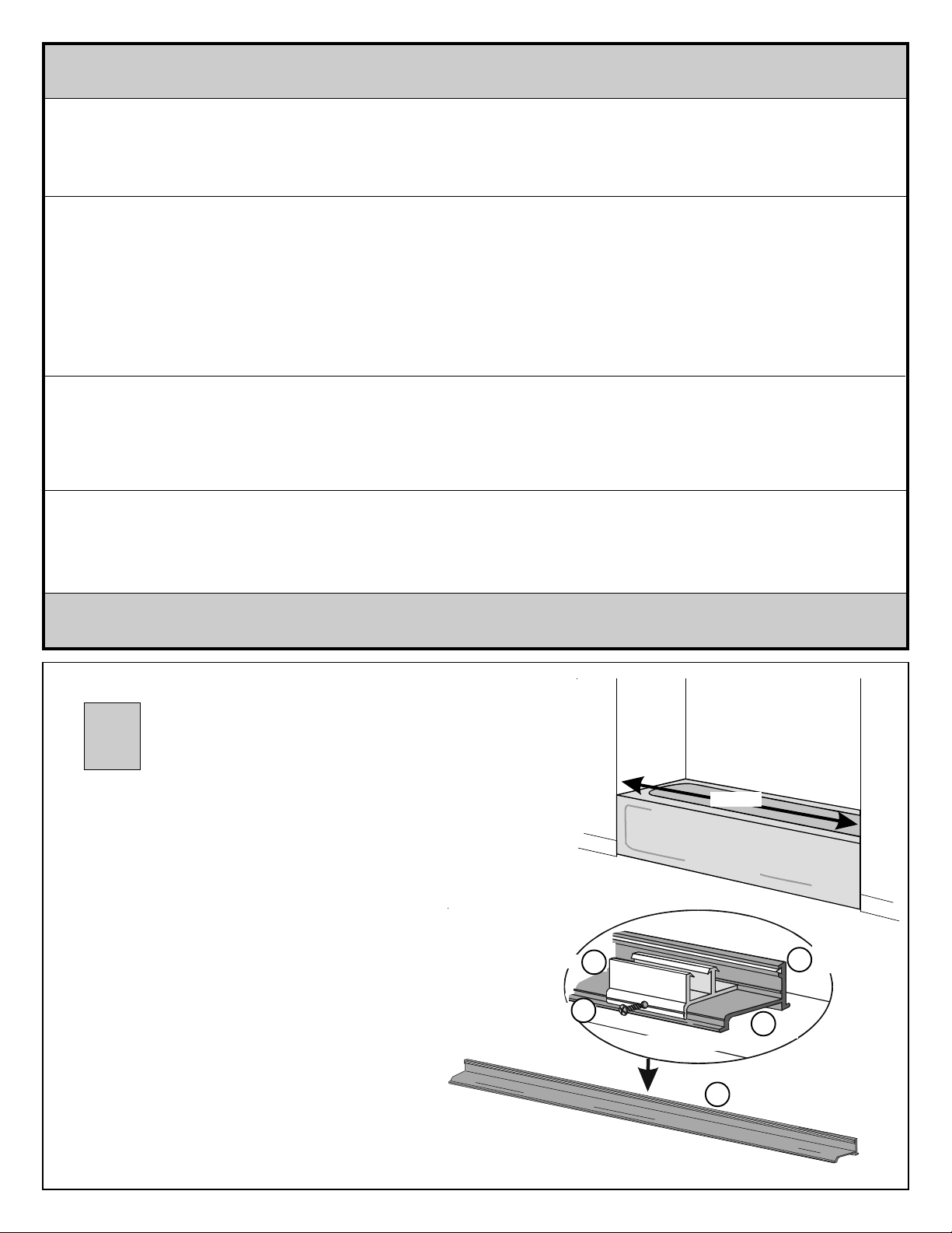
1
Measure
Measure wall to wall opening at tub level and cut sill
(A) 9/16" less than that measurement.
Slide vinyl track guide (J) into small groove on
upright of sill. Trim end flush with edge of sill.
Sill
Vinyl Track
Sill
J
Guide
Locate center of sill. Position guide (G) at center of
sill with curved leg fitting over curve of sill, and back of
guide fitting under small lip on back upright of sill.
Drill through hole in guide using 1/8" drill bit. (Chrome
and gold units include a self-drilling screw which does not
require a pilot hole.)
Guide
8A x 3/8" Pan
Head Screw
Sill
O
Sill
G
INSIDE OF BATH
Sill
A
Secure guide to sill with 8A x 3/8" pan head screw
(O).
21Y1 (BYMT) 8/01
Place guide at
center of sill.
Sill
A
Sill
Page 3
2
Level
Mark wall
through hole in
jamb and drill.
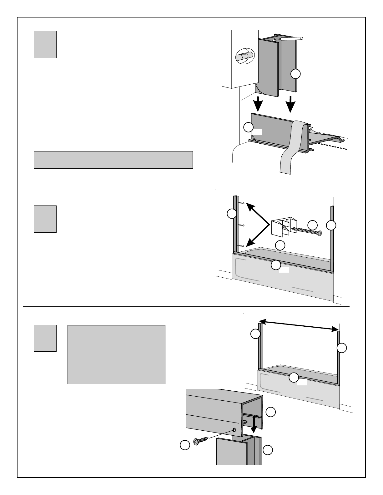
Position sill on centerline of tub with tall edge of sill toward
outside of tub. Tape sill to tub with masking tape. This will help
hold sill in place while positioning jambs.
Place one jamb (B) against wall with short legs against wall and
bottom resting firmly on sill. If necessary for a smooth fit, file back
of jamb (short legs) to fit contour of unit. Align jamb vertically
using a level and mark wall through prepunched holes. Repeat
procedure with remaining jamb.
Remove jambs and drill where marked using 1/8" drill bit.
When anchors (M) are used holes should be drilled using
3/16" drill bit. (Use masonry bit for tile.)
3
Reposition jambs on tub and mount to wall using 8A x 1 1/4 "
pan head jamb screws (H). Top and bottom holes are mounting
positions for bumpers (I).
File to fit
contour of
unit if
needed
Jamb
B
A
Sill
Masking Tape
OUTSIDE OF BATH
A
I
Sill
B
8A x 1 1/4"
Bumper
Jamb
Pan Head
Screw
H
Centerline
Jamb
B
Due to the manufacturing
4
Measure from wall to wall (over the top of both jambs)
and cut header (C) to that measurement.
Lower header over jambs until seated squarely on
legs of both jambs.
Secure header to jambs by drilling a 1/8" hole through
header into jambs on inside of tub near walls. Join
using 8A x 3/8" pan head self drilling screws (O).
process, rack marks may be
present at one end of your
header. All headers must be
trimmed to fit individual openings.
When cutting header, make
certain to trim off end with rack
marks.
O
8A x 3/8"
Pan Head Self
Drilling Screw
OUTSIDE OF BATH
Jamb
B
INSIDE OF BATH
C
Header
B
Jamb
Measure
A
Sill
Jamb
B
21Y1 (BYMT) 8/01
Page 4
5
Painted surface of designer glass
in toward shower on units with
faces
chrome, gold, or bronze metal frames.
Painted surface of designer glass
faces
outside of shower on units with
painted metal frames.
L
Towel Bar
Bracket
Pull/Stop
L
L
8A x 1 1/4"
Flat Head
Screw
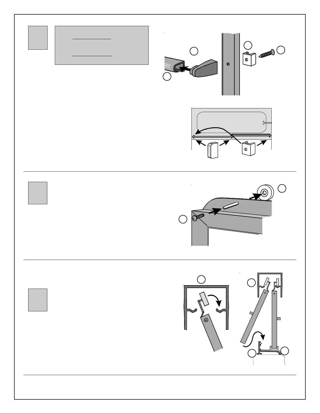
Choose door panel on which you would like towel bar to be
mounted. (Normally, towel bar is mounted on outer panel
facing outside of shower, and pull handles are on inner
panel facing inside of shower.)
Insert towel bar bracket from kit (L) into each end of towel
bar (D). Mount towel bar and pull/stop to jamb side of door
panel using 8A x 1 1/4" pan head screw. Attach opposite
end of towel bar to door panel using 8A x 1" pan head
screw.
On remaining panel, mount pull handle and pull/stop to
jamb side of panel using 8A x 1 1/4" screw. Mount remaining pull handle on opposite side of panel using 8A x 1"
screw.
6
Mount rollers (F) to top channel of doors using 8-32 x 3/8"
truss head screws (K). Rollers are to be mounted on
same side of doors as towel bars and at the midpoint of
slots.
D
Towel Bar
8-32 x 3/8"
Truss Head
Screw
Pull Handle
K
Pull/Stop
F
Roller
Rollers may be positioned up or down in slot to adjust for
out of plumb situations.
C
Header
OUTSIDE
7
Lift inside door panel into header with towel bar facing
inside of bath. Seat rollers in roller track while guiding
bottom of door into sill guide. Repeat for outside door,
hanging panel with towel bar facing outside of bath.
Seal unit by caulking along outside of enclosure where metal and bath meet, especially where sill and tub meet. If desired,
caulk inside enclosure where jambs meet walls.
OF BATH
Inside
Panel
C
Header
Outside
Panel
Sill
A
Inside
Panel
G
Guide
21Y1 (BYMT) 8/01
 Loading...