

Coral Industries 846J User Manual
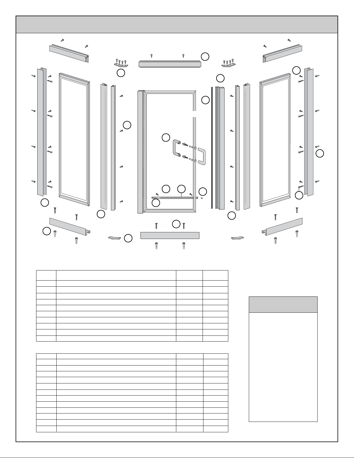
O
AG45
ALUMINUM
GUSSET
846J
MAGNETIC DOOR
A688
HEADER
C
A681
STOP
H470
TRUSS HEAD
SCREW
L
G
A682
B
JAMB
A689
A
SILL
FRAME PACKAGE
H470
TRUSS
HEAD
SCREW
L
A686
E
CORNER
POST
N
HG45
PLASTIC GUSSET
MAGNETIC
STRIP
M
PULL
HANDLE
KIT
HT52
A710
DRIP
DRIP
RAIL
RAIL
TAPE
Q
D
VS91 DRIP
R
RAIL SWEEP
H810
FLAT HEAD
J
SCREW
OUTSIDE OF SHOWER
H
H170
HA28
DRIP
RAIL
PLUG
S
F
A687
CORNER
POST
K
H479
PAN HEAD
SCREW
I
H002
ANCHOR
KEY DESCRIPTION PART QTY
A SILL A689 3
B JAMB A682 2
C HEADER A688 3
E ADJUSTABLE CORNER POST(MALE) A686 2
F ADJUSTABLE CORNER POST(FEMALE) A687 2
G MAGNETIC DOOR STOP A681 1
H MAGNETIC STRIP H170 1
D DRIP RAIL A710 1
Q DRIP RAIL TAPE
*
HT52 1
R DRIP RAIL SWEEP VS91 1
HARDWARE BAG PARTS
S DRIP RAIL PLUG HA28 1
I ANCHOR H002 14
J 8A X 1 1/4 FLAT HEAD SCREW H810 6
K 8A X 1 PAN HEAD SCREW H479 8
L 8A X 3/8 TRUSS HEAD SCREW H470 47
M TUBULAR PUSH/PULL HANDLE KIT HTSB 1
ROUND BUSHING 2
PLASTIC WASHER 4
PULL HANDLE 2
HANDLE CONECTOR SCREW 2
N PLASTIC GUSSET HG45 2
O ALUMINIUM GUSSET AG45 2
P 3/32 ALLEN WRENCH H635 1
* Pre-Installed
TOOLS NEEDED
1/8" Drill Bit
3/16" Drill Bit
(3/16" Masonry Bit for
Ceramic Tile)
Measuring Tape
Phillips Screw Driver
File
Drill
Level
China Marker
Caulking Compound
846J 10/02
INSTALLATION INSTRUCTIONS
If installation of this enclosure is planned in conjunction with a base and wall surround, make certain
that all installation steps for the base and walls have been completed before installing this enclosure.
Before starting installation of your new enclosure, carefully read all instructions
and lay out parts to become familiar with their identity. Installation is a manageable task for an
experienced "Do-It-Yourselfer" and a helper.
Do not try to cut the mirrors or glass used in this enclosure.
Tempered glass and mirrors will disintegrate if cut.
USE OF ANCHORS
Anchors are furnished with every enclosure. However, the use of anchors is not recommended when attaching your enclosure to a fiberglass
unit or wall surrounds with board reinforced mounting areas. Mounting holes in this case should be drilled with a 1/8" drill bit.
Mounting of this unit on tile requires the use of anchors. Special care must be taken not to crack the tile. Before drilling holes in the tile, lightly
chip glazed surface of tile at the desired locations. Drill holes using a 3/16" masonry drill bit. Insert anchors into the holes making certain that
ring on large end of anchor meets the surface of the tile.
CLEANING
Cleaning and care of your enclosure is important to its lasting beauty. We suggest using a nonabrasive liquid cleaner.
Never use scouring powder or pads.
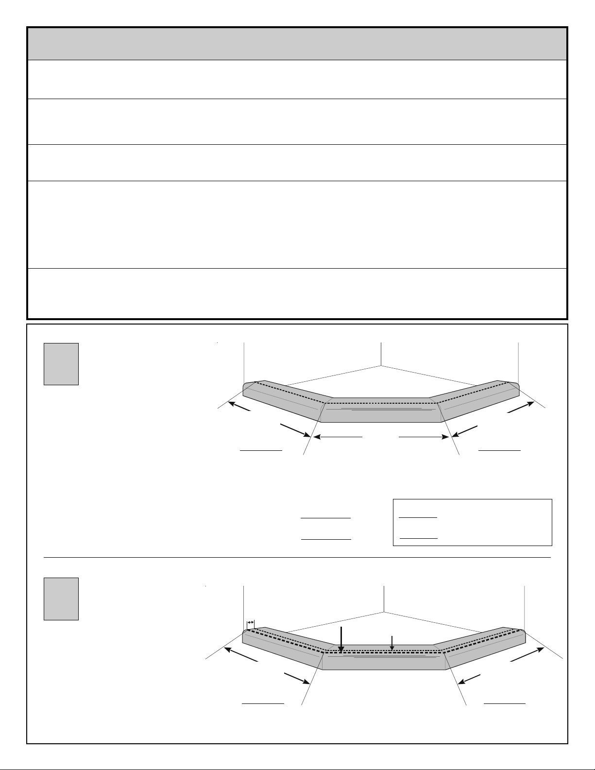
1
Measure and mark a centerline on the top
surface of your base curb using a china
marker. The measurement from the wall
to the intersection of the door and side
centerline is called the wing centerline.
Measure and record each wing centerline.
To determine that this enclosure will fit
your base, measure width of your side
panel. For this enclosure to fit your base,
your wing centerline must be at least
equal to the side panel width plus 1/2";
and at the most side panel width plus
1 3/8".
2
Measure 7/16" from the centerline drawn
in Step 1 toward outside of shower and
draw a Sill Placement Line.
The measurement from the wall to the
intersection of the door and side sill
placement lines will be the wing sill cut
lengths. Measure and record each wing
sill cut length.
Left Wing
Centerline
Door
Door
Centerline
Centerline
OUTSIDE OF SHOWER
Side Panel Width + 1/2" =
Side Panel Width + 1 3/8" =
7/16"
Sill
Placement
Line
Left Wing Sill
Cut Length
OUTSIDE OF SHOWER
Right Wing
Centerline
Compare with actual measurements:
Minimum Wing Centerline
Maximum Wing Centerline
Centerline
Right Wing Sill
Cut Length
846J 10/02
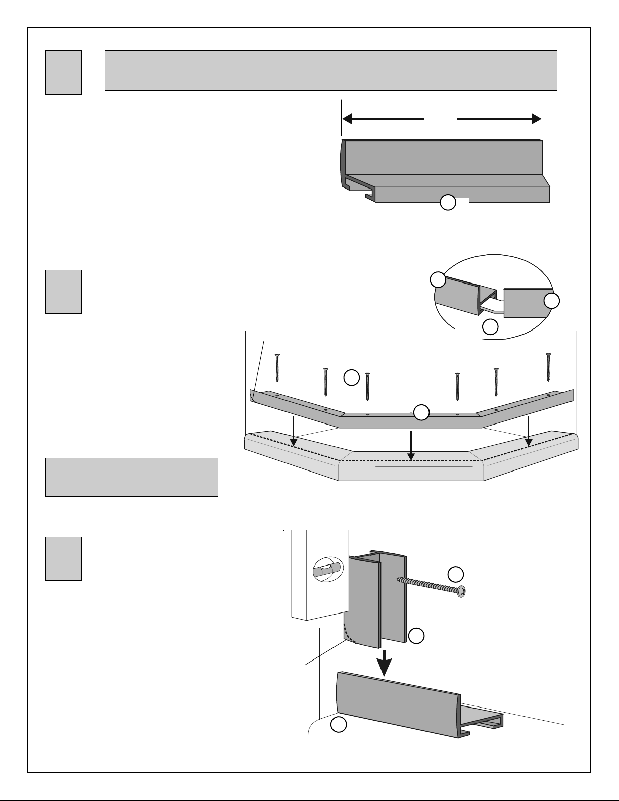
3
Due to the manufacturing process, there may be rack marks present at one end of your sill and
header. All sills and headers must be trimmed to fit individual openings. When cutting sill and header,
make certain to trim off end with rack marks.
There are three parts that make up the sill (A) -- a door sill
with two mitered (pointed) ends, and two wing sills, each
with one mitered end and one butt cut (straight) end.
The door sill is sized to fit your door and is not to be altered.
The wing sills are extra long and must be cut to match your
sill cut lenghs recorded in Step 2. Measure each sill, from
the mitered end toward the butt cut end, to the correct length
and cut. (Cut from butt cut end only.)
Join sill parts together at
mitered ends using plastic
4
Place sill on base curb, sliding sill toward
corner until butt cut ends meet walls. If
necessary for a good fit, file sharp corners of
sill to fit contour of walls.
Mark threshold through pre-punched holes in
sill. Remove sill and drill where marked
using 1/8" drill bit.
Reposition sill on base curb and secure
using 8A x 1 1/4" flat head screws (J).
gussets (N). Make certain that
ends meet tightly.
File to fit
contour of
your unit.
Mitered End
(pointed end)
8A x 1 1/4"
Flat Head
Screw
J
Wing
Sill
A
Measure
Sill
A
A
Sill
Plastic
Gusset
N
Butt Cut End
(square end)
A
Door
Sill
If anchors are used, mounting
holes should be drilled with a 3/16"
drill bit.
5
Place jamb (B) against wall with bottom
resting on sill and short legs against wall.
Align jamb vertically using level and mark
wall through pre-punched holes. If
necessary, file back edge (short legs) of
jambs to fit contour of your unit. Repeat for
remaining jamb on opposite side.
Remove jambs and drill where marked using
1/8" drill bit.
Reposition jambs and secure using 8A x 1"
pan head screws (K).
File to fit
contour your
unit.
Level
Sill
OUTSIDE OF SHOWER
A
OUTSIDE OF SHOWER
B
Jamb
K
8A x 1 "
Pan Head
Screw
846J 10/02
 Loading...