

Coral Industries 5PJ User Manual
5PJ
H470
TRUSS
HEAD SCREW
DOUBLE CHANNEL
B
A682
JAMB
J
A685
D
A681
E
MAGNETIC DOOR STOP
C
A688
HEADER
DOUBLE CHANNEL
A685
D
TRUSS HEAD
H470
SCREW
J
G
H170
MAGNETIC
STRIP
INTERIOR
HANDLE
HA28
DRIP
RAIL
PLUG
P
OUTSIDE OF SHOWER
A
PULL
L
HANDLE KIT
A710
DRIP
F
RAIL
VS91 DRIP
N
RAIL SWEEP
A689
SILL
EXTERIOR
HANDLE
HT52
DRIP RAIL
TAPE
M
I
H476
PAN HEAD
SCREW
H
H002
ANCHOR
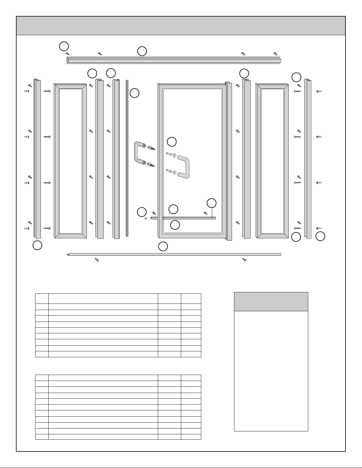
FRAME PACKAGE
KEY DESCRIPTION PART QTY
A SILL A689 1
B JAMB A682 2
C HEADER A688 1
D DOUBLE CHANNEL A685 2
E MAGNETIC DOOR STOP A681 1
F DRIP RAIL A710 1
G MAGNETIC STRIP H170 1
M DRIP RAIL TAPE
N DRIP RAIL SWEEP VS91 1
*
HT52 1
HARDW ARE BAG PARTS
P DRIP RAIL PLUG HA28 1
H ANCHOR H002 8
I 8A X 1 PAN HEAD SCREW H476 8
J 8A X 3/8 TRUSS HEAD SCREW H470 24
K ALLEN WRENCH 1
L PUSH / PULL HANDLE KIT HTG6 1
PLASTIC WASHER 4
EXTERIOR PULL HANDLE 1
INTERIOR PULL HANDLE 1
BUSHING 2
HANDLE CONNECTOR SCREW 2
* Pre-Installed
TOOLS NEEDED
1/8" Drill Bit
3/16" Drill Bit
(3/16" Masonry Bit for
Ceramic Tile)
Scratch Awl
Measuring Tape
Hacksaw
Phillips Screw Driver
Caulking Compound
File
Drill
Level
Masking Tape
5PJ 8/02
INSTALLATION INSTRUCTIONS
Before starting installation of your new enclosure, carefully read all
instructions and lay out parts to become familiar with their identity.
USE OF ANCHORS
Anchors are furnished with every enclosure. However, the use of anchors is not recommended when attaching your enclosure to a fiberglass
unit or wall surrounds with board reinforced mounting areas. Mounting holes in this case should be drilled with a 1/8" drill bit.
Mounting of this unit on tile requires the use of anchors. Special care must be taken not to crack the tile. Before drilling holes in the tile, lightly
chip glazed surface of tile at the desired locations. Drill holes using a 3/16" masonry drill bit. Insert anchors into the holes making certain
that ring on large end of anchor meets the surface of the tile.
CLEANING
Cleaning and care of your enclosure is important to its lasting beauty. We suggest using a nonabrasive liquid cleaner.
Never use scouring powder or pads.
SEALING
The use of a caulking compound can assure a watertight seal when applied along outside edge of the enclosure where metal and bath meet. If
desired, caulk inside of enclosure where jambs meet walls.
Do not try to cut the mirrors or glass used in this enclosure. • Tempered glass and mirrors will disintegrate if cut.
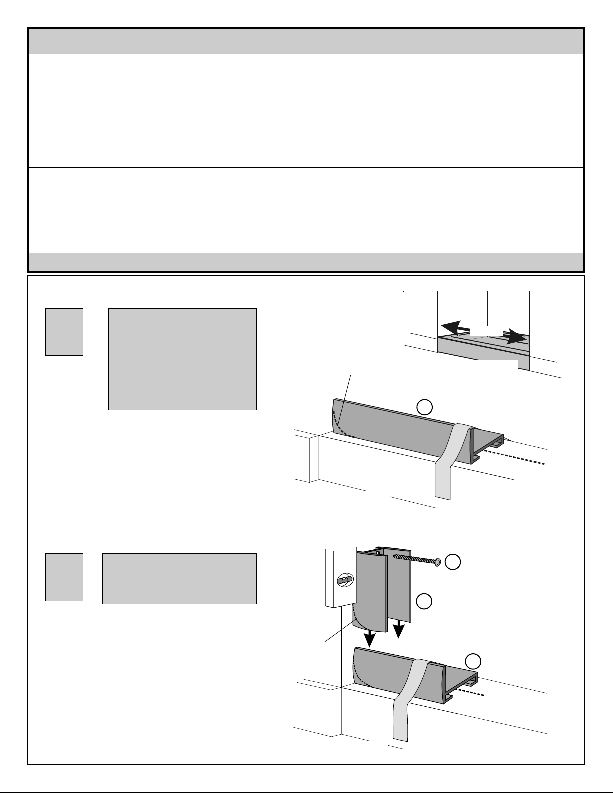
Due to the manufacturing
1
process, there may be rack
marks present at one end of
your sill and header. All sills
and headers must be trimmed
to fit individual openings. When
cutting sill and header, make
certain to trim off end with rack
marks.
File sharp corners of
sill as necessary to fit
contour of your unit
Sill
OUTSIDE OF SHOWER
A
Measure
Measure opening at threshold of shower and cut
sill (A) to that measurement. If necessary, file
sharp corners of sill to fit contour of your unit.
Position sill on center of threshold with tall edge of
sill toward outside of shower. Tape sill to threshold
with masking tape to hold in place while positioning
jambs.
When anchors (H) are used,
holes should be drilled using
2
Place jamb (B) on sill with short legs against wall.
If necessary, file sharp corners on back of jamb to
fit contour of your unit.
Align jamb vertically using a level and mark wall
through prepunched holes. Remove jamb and drill
where marked using 1/8" drill bit. Repeat for
remaining jamb on opposite side.
3/16" drill bit. (Use masonry
bit for tile.)
OUTSIDE OF SHOWER
Contour as
needed
Level
Threshold
B
Jamb
Masking
Tape
I
Pan Head
8A x 1"
Screw
Sill
A
Centerline
Centerline
Reposition jambs on wall and secure using
8A x 1" pan head screws (I).
5PJ 8/02
OUTSIDE OF SHOWER
 Loading...