

Page 1
HA 440
3/4-channel power amplifier
Page 2
HA 440 - 3/4-CHANNEL POWER AMPLIFIER
[ 1 ] [ 2 ] [ 3 ] [ 4 ] [ 5 ] [ 6 ] [ 8 ] [ 9 ] [ 10 ] [ 7 ]
-
+
A
B
HA 440
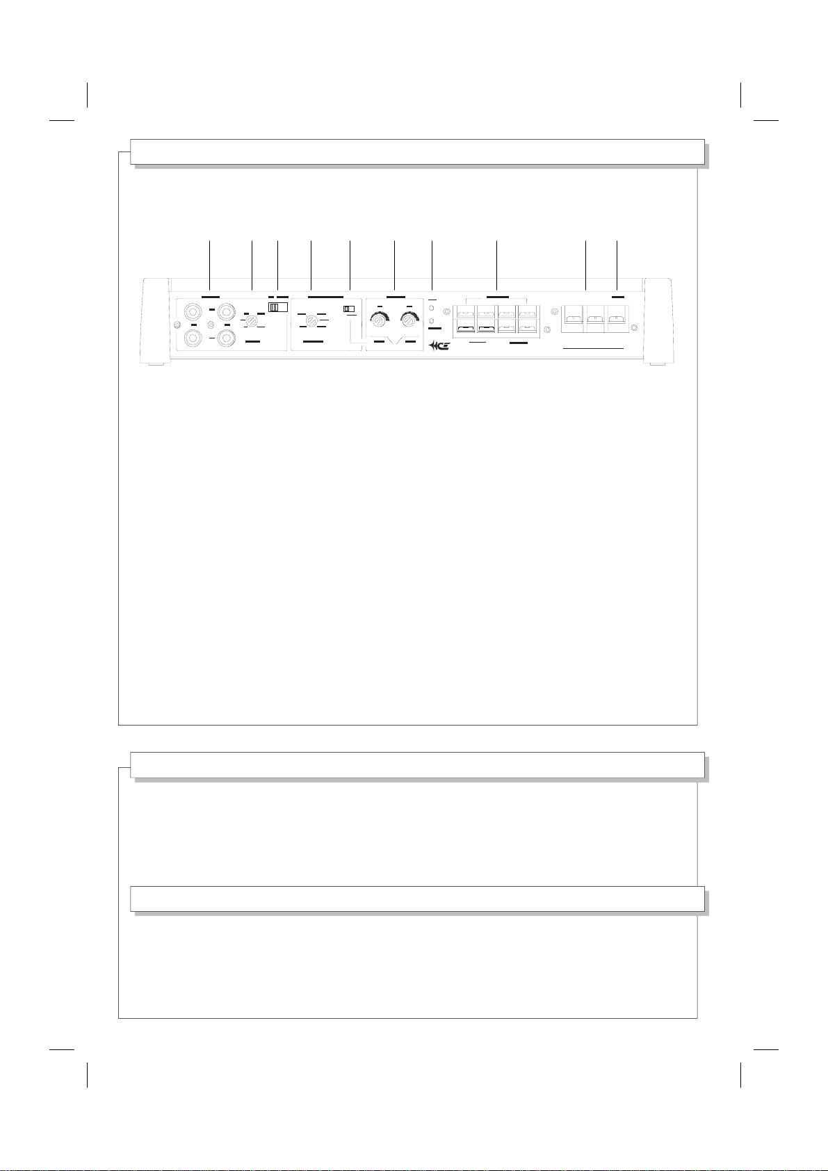
1 - RCA INPUTS
Connettori d'ingresso RCA,
sinistro e destro dei canali A e B.
RCA input jacks,
Left and Right of A and B channels.
2 - INPUT SENSITIVITY
Regola la sensibilità d'ingresso.
Adjusts the input sensitivity.
3 - INPUT SWITCH
Seleziona i connettori d'ingresso RCA.
Sets the RCA input jacks.
4 - MSC SYSTEM CONTROL
Regola la frequenza d'incrocio.
Adjusts the crossover frequency.
5 - MSC SYSTEM SWITCH
Attiva/disattiva la funzione MSC.
Sets the MSC on/off status.
6 - OUTPUT LEVEL CONTROLS
M O L T O I M P O R T A N T E !
Regolano i livelli delle uscite A e B.
Adjust the A/B output levels.
7 - ON/SAFE LEDS
Indicano l'attivazione dell'amplificatore
e l'intervento delle protezioni.
Make known the amplifier ON status
and the protection shut-down.
8 - SPEAKER OUTPUTS
Morsetti altoparlanti canali A e B.
A and B channel speaker connectors.
9 - POWER SUPPLY
Morsetti alimentazione 12 Volt.
12 Volt power supply connectors.
10 - REMOTE
Morsetto accensione remota.
Remote on/off connector.
E' necessario leggere attentamente questo manuale
e seguire passo-passo le istruzioni
per ottenere le migliori prestazioni dall'amplificatore
e prevenire l'insorgere di eventuali problemi.
V E R Y I M P O R T A N T !
It is necessary to carefully read this manual
and follow the directions step by step
to obtain the best results from the amplifier
and to prevent against possible problems.
Page 3
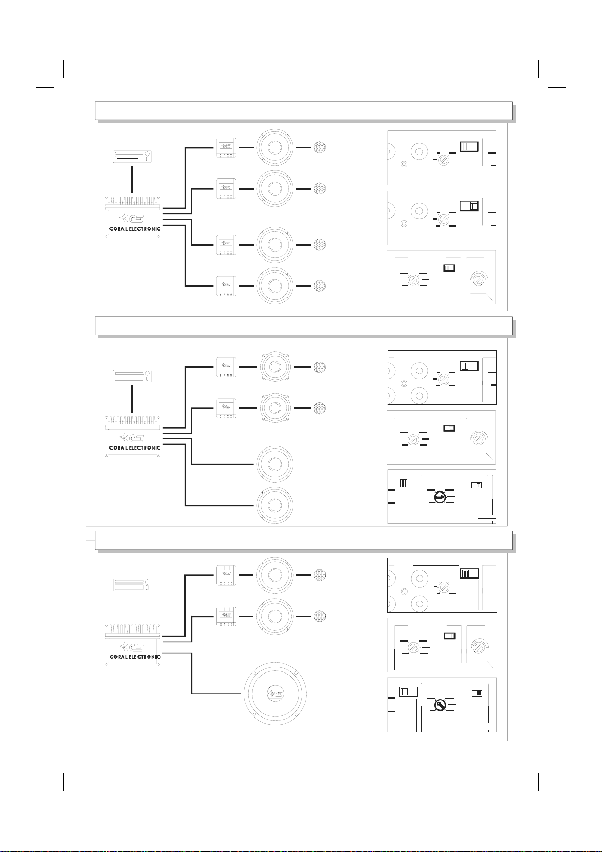
4-SPEAKER SYSTEM USE
X-OVER WOOFER TWEETER
MSC : BI-POWERED 3-WAY SYSTEM
X-OVER MIDRANGE TWEETER
INPUT
R
B
A+BA
ONE CABLE FROM RADIO
INPUT
R
B
A+BA
TWO CABLES FROM RADIO
HERTZ
INPUT
R
L
MSC SYSTEM
B
VOLT
MSC SYSTEM
A
ON
L-P
A A+B
A
ON
LEV
LEV
WOOFER
MSC : 2-WAY SYSTEM / ACTIVE SUBWOOFER
X-OVER WOOFER TWEETER
SUBWOOFER
HERTZ
A+BA
INPUT
R
L
HERTZ
A+BA
HERTZ
B
MSC SYSTEM
HERTZ
L-P
MSC SYSTEM
ON
A A+B
VOLT
LEV
A
ON
L-P
MSC SYSTEM
ON
Page 4
MOUNTING
RCA INPUTS
FM 101.5 - R D S
NO
OK
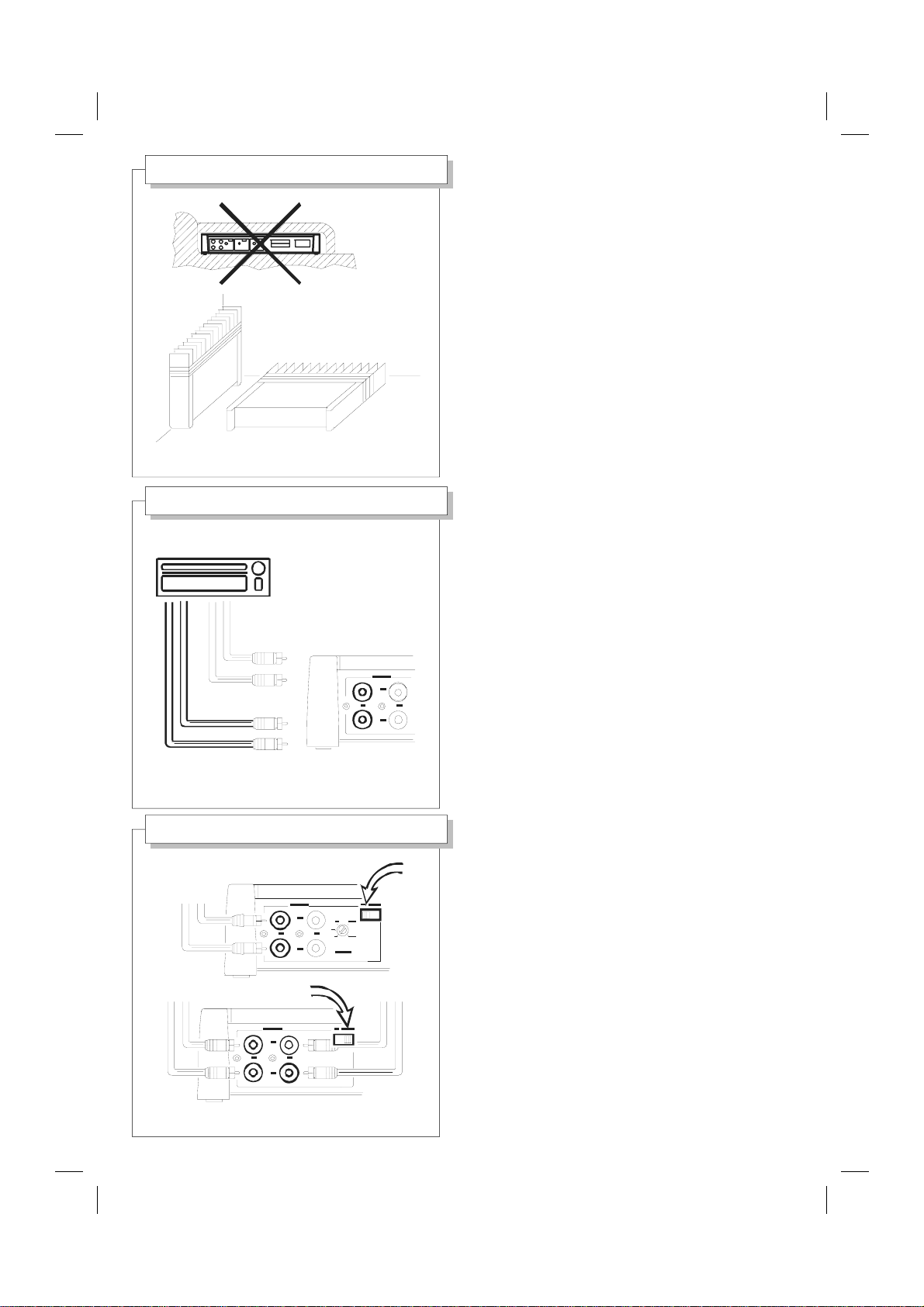
Per un funzionamento sicuro, posizionate l'amplificatore
in un luogo ben aerato e protetto da polvere ed umidità.
Ricordate che tutti gli amplificatori producono calore
durante il funzionamento e forniscono le migliori prestazioni
solo se correttamente raffreddati.
Non installate l'amplificatore in un vano troppo piccolo
per assicurare una buona aereazione.
Avvitate l'amplificatore ad una solida superficie.
For a safe operation, put the amplifier in a place with a
good ventilation and protected from dust and moisture.
Remember that all amplifiers produce heat during operation
and they will perform better just if they are kept cool.
Do not mount the amplifier in a place too small
to ensure a good airflow.
Screw up the amplifier on a steady surface.
Collegate l'autoradio agli ingressi dell'amplificatore [1]
con cavo schermato di buona qualità con connettori RCA.
Connect the car radio to the amplifier inputs [1]
by good quality coaxial cable with RCA connectors.
INPUT SWITCH
Scegliete la posizione del deviatore d'ingresso [3].
"A" per collegare una sola coppia di cavi all'autoradio.
Lo stesso segnale è presente
su entrambi i morsetti d'uscita [8] "A" e "B".
Il controllo fader della sorgente non è attivo.
"A+B" per collegare due coppie di cavi all'autoradio.
Il controllo fader della sorgente è attivo.
Choose the right position of input switch [3].
"A" to connect just one couple of cables from car radio.
The same signal is present on both
"A" and "B" output connectors [8].
The source fader control is not active.
"A+B" to connect two couples of cables from car radio.
The source fader control is active.
Page 5
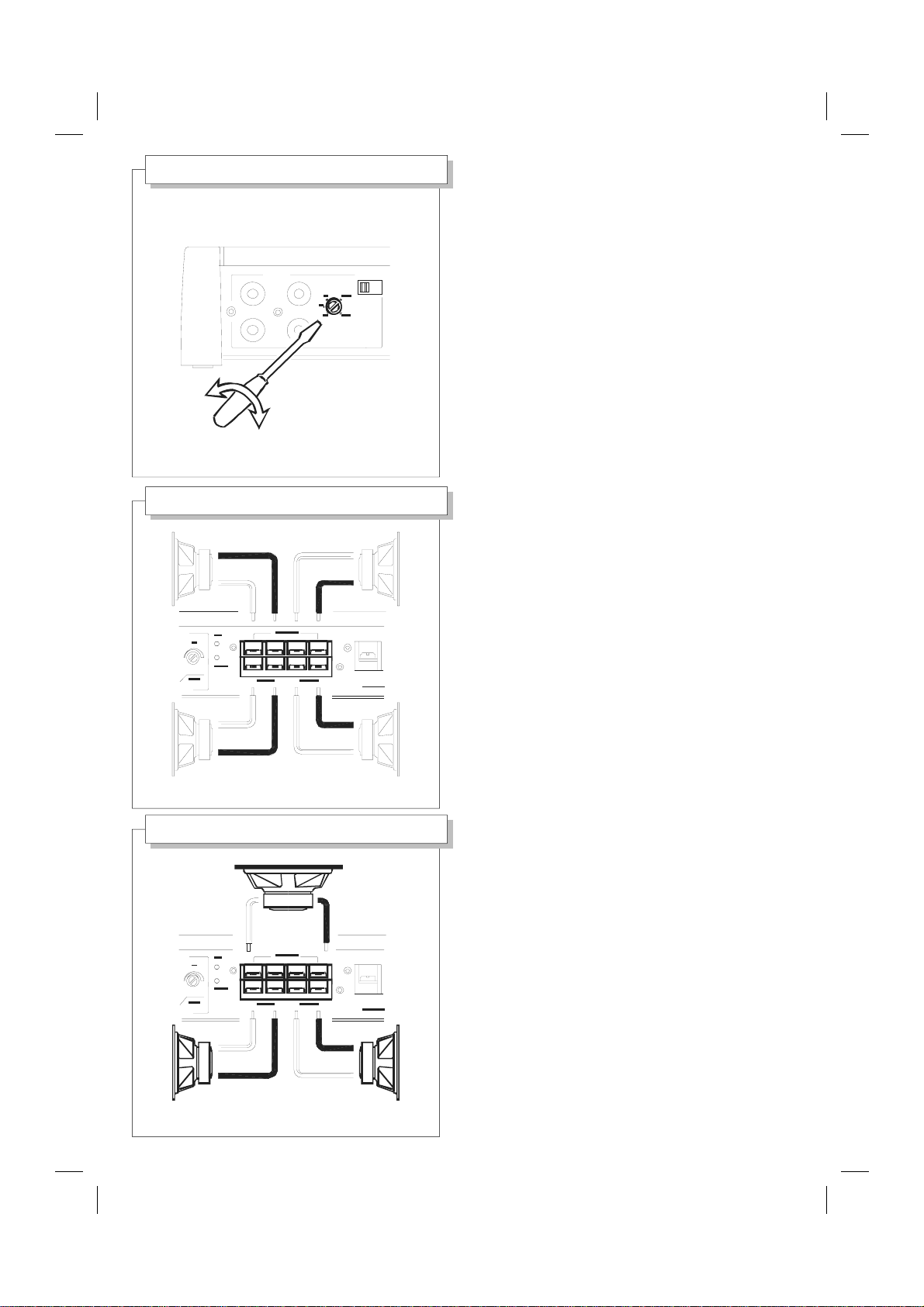
INPUT SENSITIVITY
INP UT
A
4-SPEAKER USE
-
+
-
Consultate il manuale d'istruzioni dell'autoradio
e verificate la tensione d'uscita del segnale (0,4 ÷ 4 Volt).
Regolate la sensibilità d'ingresso agendo sul controllo [2].
Consult the car radio instruction manual
A+BA
R
B
L
VOLT
and check the signal output voltage (0,4 ÷ 4 Volt).
Adjust the input sensitivity by the control [2].
Collegate quattro altoparlanti (o quattro sistemi di
+
-+
+
A
B
HA
-
+
altoparlanti) ai connettori [8], rispettando le polarità.
Collegate il sistema anteriore su "A"
ed il sistema posteriore su "B".
Utilizzate cavi di adeguata sezione (1÷2 mm
Utilizzate altoparlanti di adeguata potenza.
Non collegate mai insieme i negativi (-) d'uscita.
2
).
Non collegate mai a massa alcun altoparlante.
Connect four speakers (or four speaker systems)
to the connectors [8], keeping the polarities.
Connect the front system on "A"
and the rear system on "B".
Use right section speaker cables (1÷2 mm
Use right power handling loudspeakers.
Never link together the negative (-) outputs.
2
).
Never connect to ground any speakers.
3-SPEAKER USE
+
-
+-
A
B
Collegate due altoparlanti (o due sistemi di altoparlanti)
ai connettori [8], uscita "B", rispettando le polarità.
Collegate il subwoofer su "A", come in figura.
Utilizzate cavi di adeguata sezione (1÷2 mm
Utilizzate altoparlanti di adeguata potenza.
2
).
Non collegate mai insieme i negativi (-) d'uscita.
+
Non collegate mai a massa alcun altoparlante.
Connect two speakers (or two speaker systems)
HA
-
to the connectors [8], "B" output, keeping the polarities.
Connect the subwoofer on "A", like in the picture.
Use right section speaker cables (1÷2 mm
Use right power handling loudspeakers.
2
).
Never link together the negative (-) outputs.
+
Never connect to ground any speakers.
Page 6
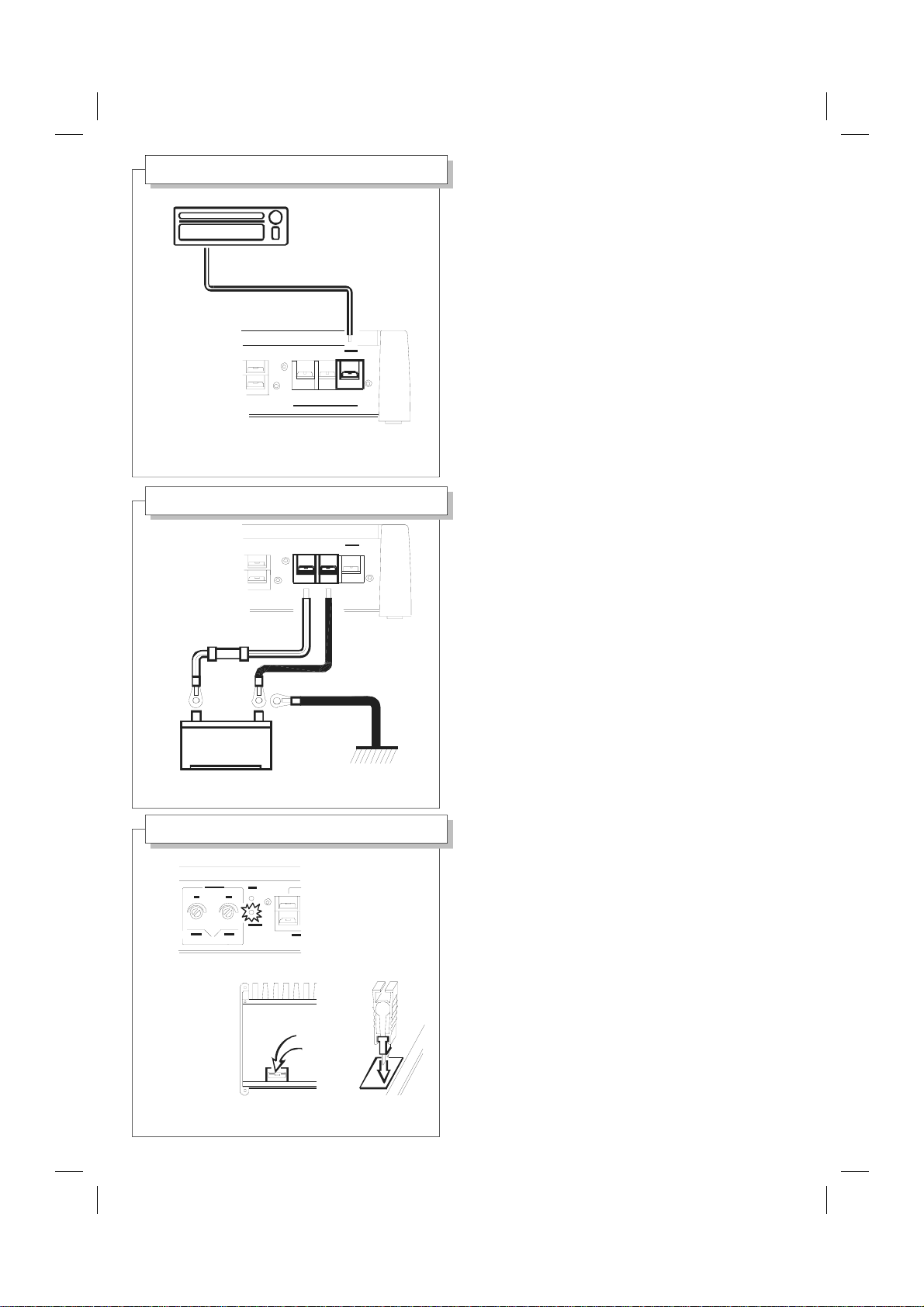
REMOTE ON/OFF
FM 101. 5 - R D S
REMOTE OUT
POWER SUPPLY
FUSE
40A
+
BATTERY
Collegate l'uscita remote dell'autoradio al morsetto [10]
dell'amplificatore, con un piccolo cavo elettrico (1 mm
2
).
Connect the car radio remote output to the amplifier
connector [10], by a small electrical cable (1 mm
2
).
+-
A
B
HA 440
Collegate i morsetti d'alimentazione [9]
A
+-
direttamente alla batteria, rispettando le polarità.
Utilizzate cavi di adeguata sezione (6 mm
2
).
Inserite un fusibile da 40 A, vicino alla batteria,
B
sul cavo positivo, per proteggere la vettura.
Il fusibile interno all'amplificatore
non sostitisce quello sulla batteria.
Connect the supply connectors [9]
directly to the battery, keeping the polarities.
Use right section power cables (6 mm
2
).
Place a 40 A fuse, near the battery,
-
GND
on the positive conductor, to protect the vehicle.
The internal fuse does
not substitute the battery fuse.
ON/SAFE LEDS - FUSE
INTERNAL
FUSE
Il led ON (verde) indica che l'amplificatore è acceso.
Il led SAFE (rosso) segnala un malfunzionamento,
l'amplificatore si spegne automaticamente.
Controllate attentamente tutto l'impianto.
Dentro l'amplificatore è presente un fusibile.
Se necessario, rimpiazzatelo con uno uguale.
Non sostituite il fusibile prima di aver rimosso la causa del
guasto, ciò provocherebbe danni alla circuitazione.
The ON led (green) shows that the amplifier is on.
The SAFE led (red) makes known a malfunction,
the amplifier turns off automatically.
Check carefully all the system.
There is a fuse inside the amplifier.
If necessary, replace it whit one of the same type.
Do not replace the fuse before having take away the cause
of damage, as this can damage the internal circuit.
Page 7
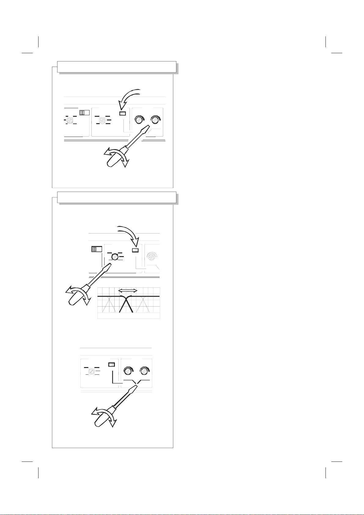
MSC SYSTEM SWITCH
A+BA
MSC SYSTEM
VOLT
HERTZ
MSC SYSTEM USE
A
MSC SYSTEM
A+B
HERTZ
70 100 300 600
ON
LEVEL
AB
H-P
A
ON
L-P
Scegliete la posizione del deviatore MSC [5].
A sinistra il circuito è disattivato.
L'amplificatore è un normale quattro canali.
I controlli level [6] agiscono sul bilanciamento fronte/retro.
A destra (ON) il circuito è attivato.
Il deviatore d'ingresso [3] deve essere su "A".
Choose the right position of MSC switch [5].
On left the circuit is disarmed.
The amplifier is a normal 4-channel unit.
The level controls [6] adjust the front/rear balance.
On right (ON) the circuit is active.
The input switch [3] has to be on "A".
Posizionate il deviatore d'ingresso [3] su "A".
Posizionate il deviatore MSC [5] su "ON".
Il circuito MSC è attivato.
Scegliete la giusta frequenza d'incrocio
tra i canali "A" e "B" agendo sul controllo MSC [4].
Il sistema MSC separa le frequenze dei canali "A" e "B",
invia la gamma bassa sul morsetto d'uscita [8] "A"
e le frequenze medio-alte sul morsetto d'uscita [8] "B".
I controlli level [6] agiscono
sul bilanciamento tonale dell'impianto.
Set the input switch [3] on "A".
Set the MSC switch [5] "ON".
The MSC circuit is active.
Choose the right crossover frequency
between "A" and "B" channels by MSC control [4].
The MSC system divides
the frequencies of "A" and "B" channels, sending
the low range to the output connector [8] "A" and
the mid-high frequencies to the output connector [8] "B".
The level controls [6] work on system tonal balance.
MSC SYSTEM
HERTZ
LEVEL
ON
BA
L-P
H-P
Page 8
Technical data
music power
W
rms power (4 ohm) W
rms power (2 ohm) W
rms power (4 ohm - 3 channels) W
load impedance Ohm
MSC crossover frequency Hz
MSC filter slope dB/oct
frequency response Hz
T.H.D. %
S/N ratio dB
input sensitivity mV
input impedance Ohm
current consumption A
size (L x W x H) mm
HA 440
4 x 90
4 x 45
4 x 60
2 x 45 + 1 x 120
2 - 4 - 8
70 -600
12
12 - 20 K
0.18
98
400 - 4000
20 K
40
284 x 210 x 48
Coral Electronic warranty
Coral Electronic garantisce le caratteristiche ed il perfetto
funzionamento dei suoi prodotti.
Per garanzia si intende la riparazione o sostituzione di
quelle parti che, a suo insindacabile giudizio, risultassero
difettose di fabbricazione.
E' esclusa la sostituzione integrale.
Non si riconoscono danni comunque conseguiti.
L'apparecchio e' garantito per un anno dalla data di
acquisto, certificata da fattura, ricevuta o scontrino fiscale.
L'assistenza è data dai laboratori autorizzati.
Le spese ed i rischi di trasporto sono a carico dell' acquirente, che dovrà provvedere ad un adeguato imballaggio.
La garanzia decade in caso di manomissione.
Questo certificato NON deve essere spedito per la
convalida, ma deve accompagnare l'apparecchio difettoso
in caso di intervento.
Coral Electronic srl - 10090 Rivoli - Torino - Italy - corso Allamano 74
tel (+39) 011 959 44 55 - fax (+39) 011 957 23 55
Coral Electronic warrants the characteristics and the
perfect operation of each Coral product.
Coral will repair or replace those parts which you can prove
to be defective, at its option.
Integral replacement is excluded.
Coral will not be liable for any damage in any way
occurred.
Coral products are warranted for one year from the date of
purchase, stated by the sales receipt voucher.
Warranty service is given only by the authorized
laboratories.
Shipping, packing and related risks charges are paid by
the original purchaser.
In case of misuse this warranty is void.
This certificate must NOT be sent to Coral for confirmation.
It has to be sent with the defective unit, in case of service,
together with the sales receipt.
 Loading...