

Page 1
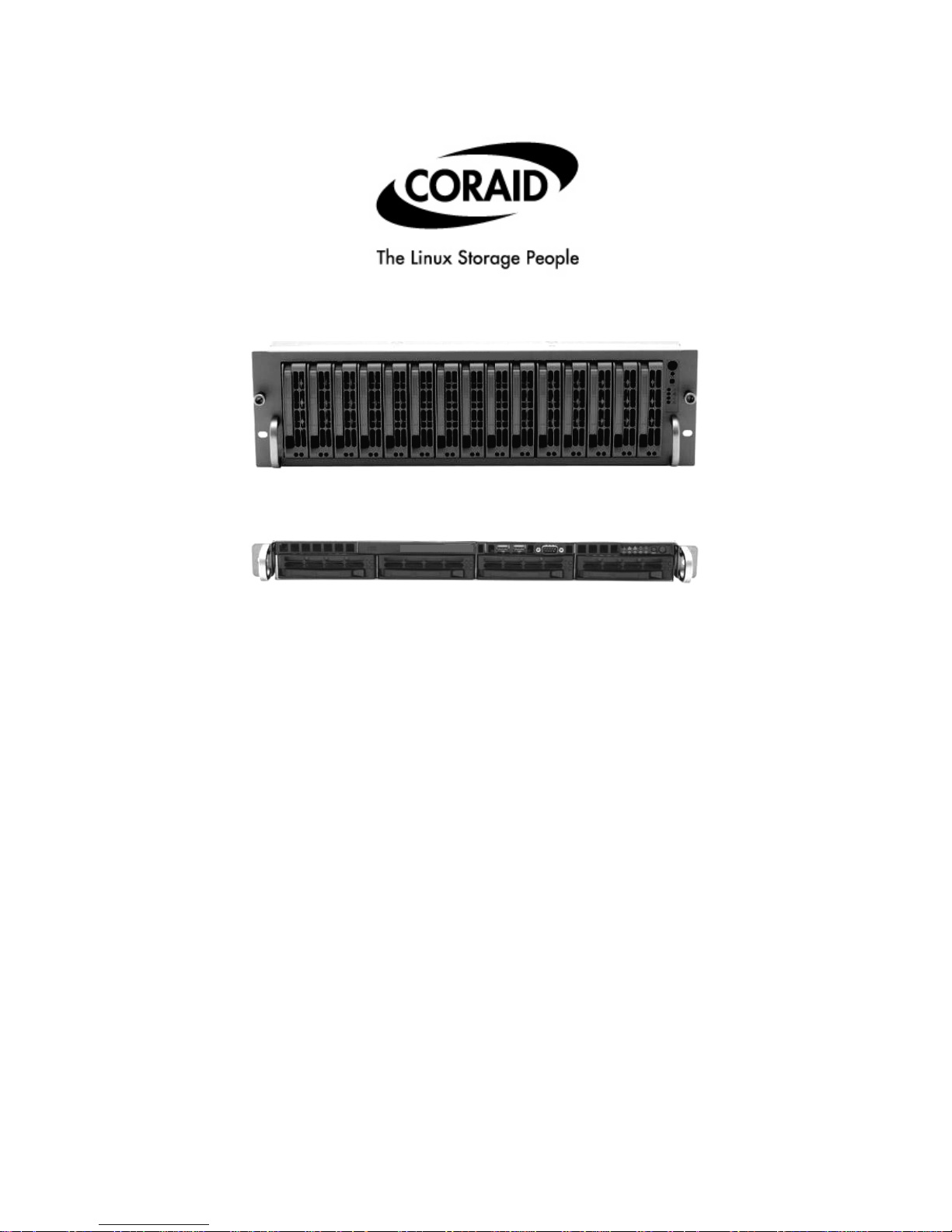
SATA EtherDrive Storage
SR1520 (3U - 15Disk)
SATA EtherDrive Storage
SR420 (1U - 4Disk)
EtherDrive® Storage
Installation Guide
Updated 4 March 2006
Coraid Inc. Page 1
Page 2
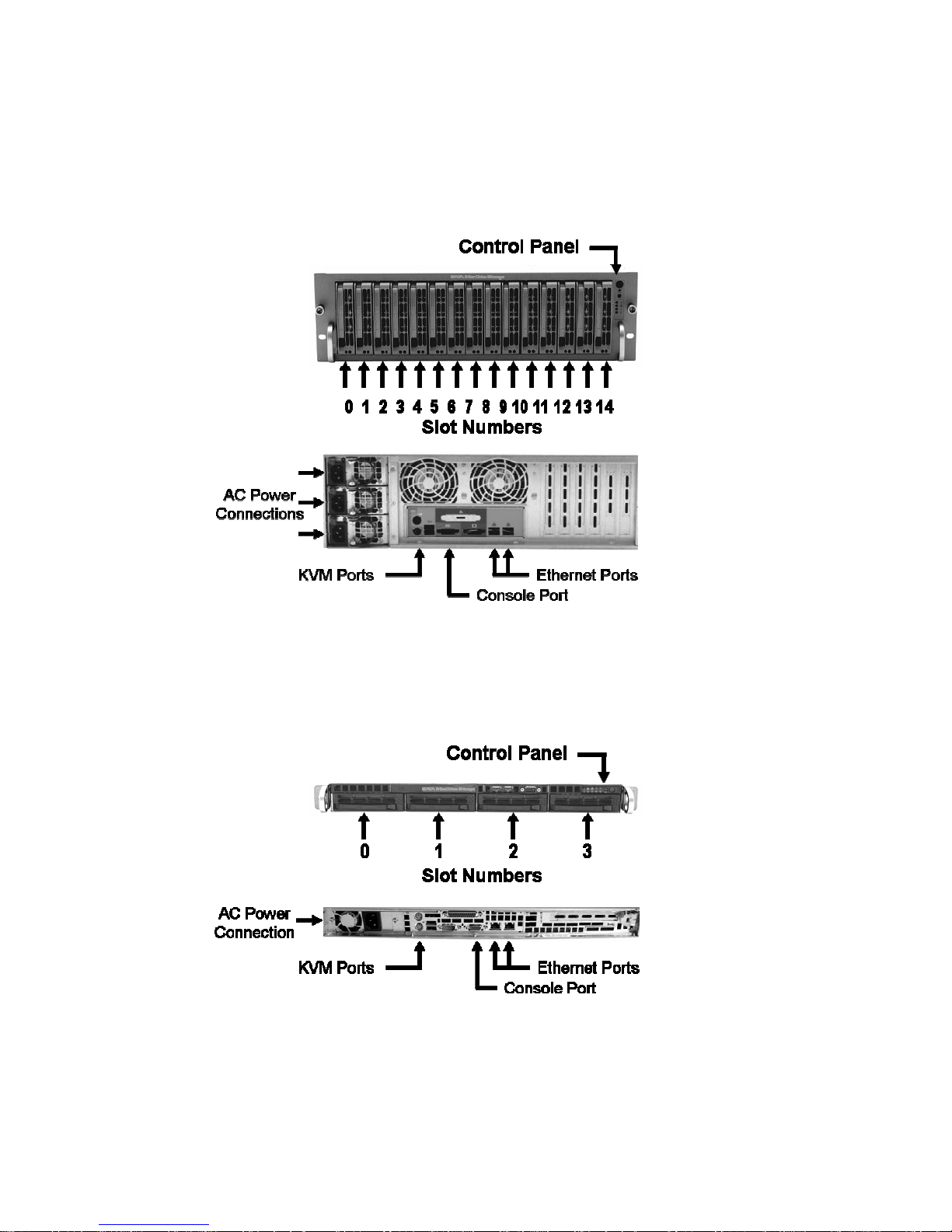
Thank you for purchasing EtherDrive
device accessed using the ATA-over-Ethernet (AoE) protocol.
EtherDrive
disks.
®
Storage consists of a cabinet (4 post rack) mounted appliance equipped with slots for SATA
®
Storage. A simple Ethernet connected shared disk storage
SR1520 – Model # CED3U15SS
SR420 – Model # CED1U4SS
Coraid Inc. Page 2
Page 3
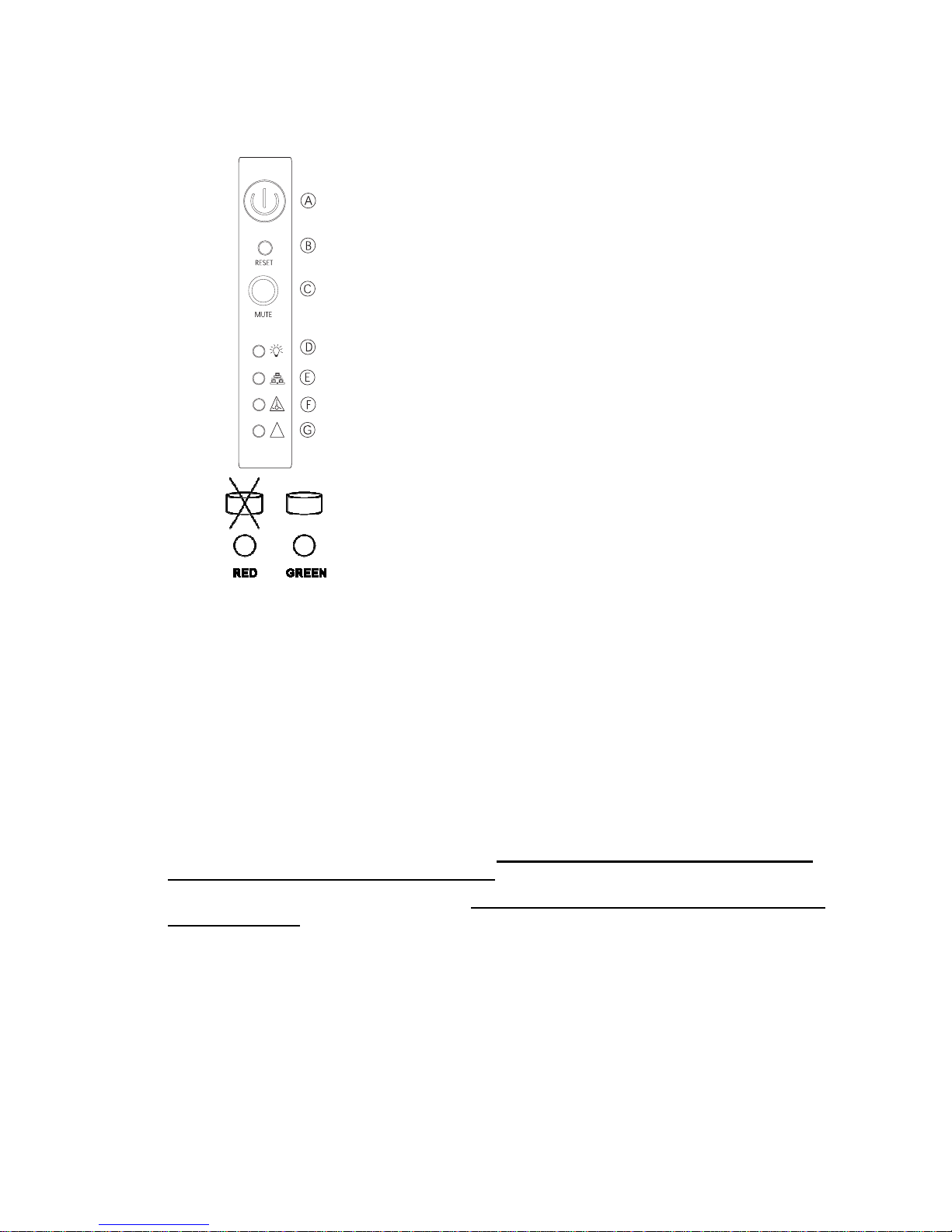
Control Panel and Indicator LEDs
The EtherDrive
®
Storage shelf is equipped with color LED indicators and buttons located on the front
panel.
!
A. PowerOn/Off Red Button – Toggles unit power on and off.
B. Reset Button (recessed) – Pressing reset, causes system to
reboot.
C. Alarm Mute Button – Normally “OFF” Red, turned “ON” only
when Blade has detected a fault and halted, indicating the
Blade must be removed and serviced.
D. Power On Green LED – “ON” Green when unit power is turn
on.
E. Network Activity Green LED – Flashes “ON/OFF” Green on
any detected Ethernet activity.
F. High Temperature Alarm Red LED – “ON” Red when chassis
internal temperature exceeds 40°C.
G. Power Supply Fail Alarm Red LED – “ON” Red during power
supply module failed.
Each disk carrier also has two light pipe indicators
to show disk status. Red “On” when disk has failed
and Green “Flashing/On” during disk activity.
Package Contents
• One CED3U15SS (or CED1U4SS) shelf assembly
• IEC power cord(s)
• Two slide out cabinet mounting rail assemblies
• Screws to mount SATA disk to disk drive trays
Safety Precautions
• CED3U15SS weighs more than 50 pounds. Use 2 people to lift unit to avoid injury.
• CED3U15SS has hot swap power modules.
Disconnect the power cord from the power
supply module before removing the module.
• CED3U15SS has hot swap internal fans.
Use extreme caution when opening top cover to
replace a fan unit.
• CED1U4SS has no hot swap serviceable components.
Coraid Inc. Page 3
Page 4
Quick Installation in 3 easy steps
1. Cabinet Installation and Power Connection
a. Mount the shelf into the desired cabinet location. We recommend the sys admin/installer attach a unique
shelf number label to the front of the cabinet rail for easy storage unit identification. This shelf number will
be used by the sys admin in the first steps of configuration via the storage units console port once physical
installation is complete.
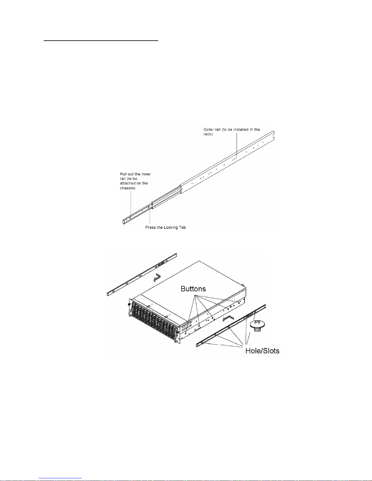
i. Included in the shipping package is a pair of rail assemblies. In each rail assembly, locate the inner rail
and the outer rail. Press the locking tab to release the inner rail from its locking position and pull out the
inner rail from the rail assembly. (*The inner rails are to be attached to the chassis and the outer rails are
to be installed in the rack.)
ii. Locate the five rail buttons on each side of the chassis and locate the five corresponding holes on each of
the inner rail. (*Please note that one end of the hole is larger than the other end of the hole.)
iii. Align the larger end of each hole against its corresponding button. Once all aligned, push the holes toward
their corresponding buttons and the rail is placed on the chassis. Once the rail is placed on the chassis,
pull the rail forward until the rail buttons lock in the small ends of the corresponding holes . Secure the rail
to the chassis with a screw provided. Repeat the above steps to install other rail on the chassis.
iv. After you have installed the inner rails on the chassis, you are ready to install the outer rails of rail
assemblies to the rack. (* The rails are designed to fit in the cabinets with the depth of 28" to 33".) Locate
a pair of front (-short) and rear (-long) brackets provided. Please note that the brackets are marked with
Up/Front Arrows (-front) and Up/Rear arrows (-rear). Secure the front (-short) bracket (marked with the
Up/Front arrows) to the outer rail with two screws provided.
Coraid Inc. Page 4
Page 5
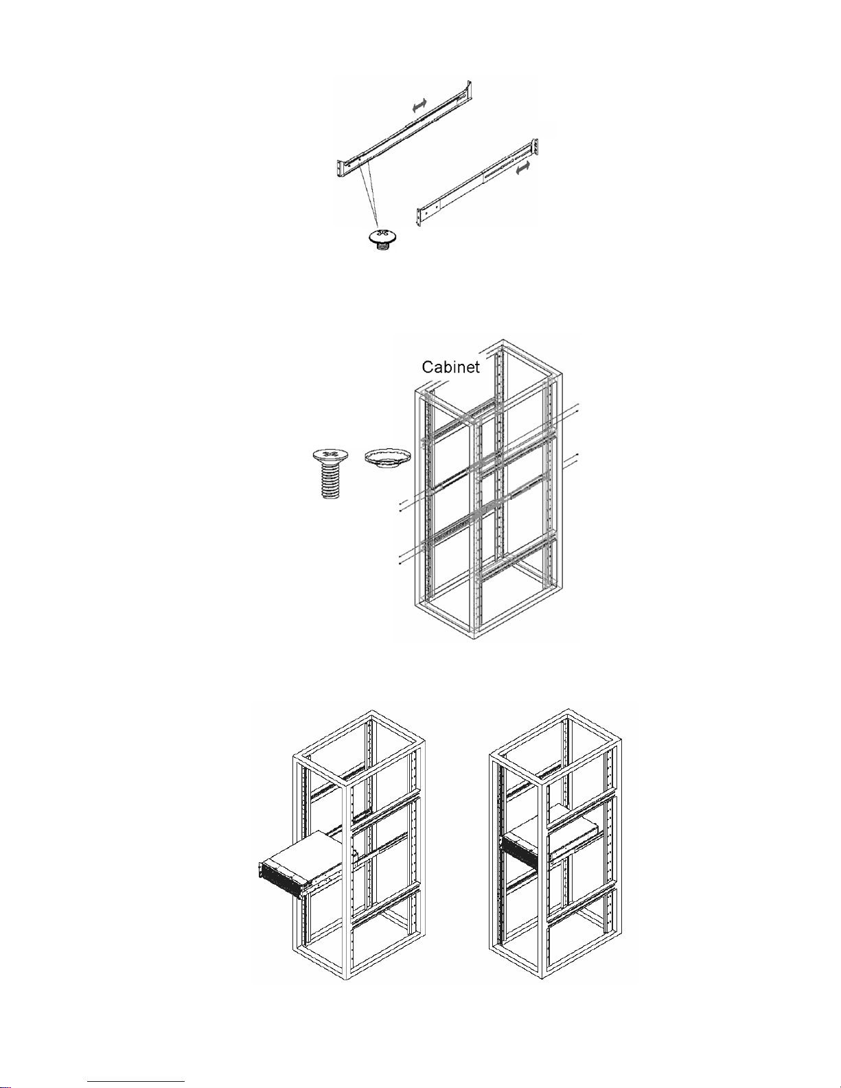
v. Locate the two buttons on the outer rail and attach the rear (-long) bracket to it by sliding the opening of
the rear rail through the button. Measure the depth of your rack and adjust the length of the rails
accordingly. Repeat the same steps install the other outer rail on the chassis.
vi. Secure both outer rail assemblies to the cabinet with screws and washers.
vii. Once the rail assembli es are securely installed on the cabinet, slide the CED3U15SS (or CED1U4SS)
chassis into the rail assemblies as shown below: (Note some rail screw adjustment may be require to
achieve smooth sliding in and out)
Coraid Inc. Page 5
Page 6
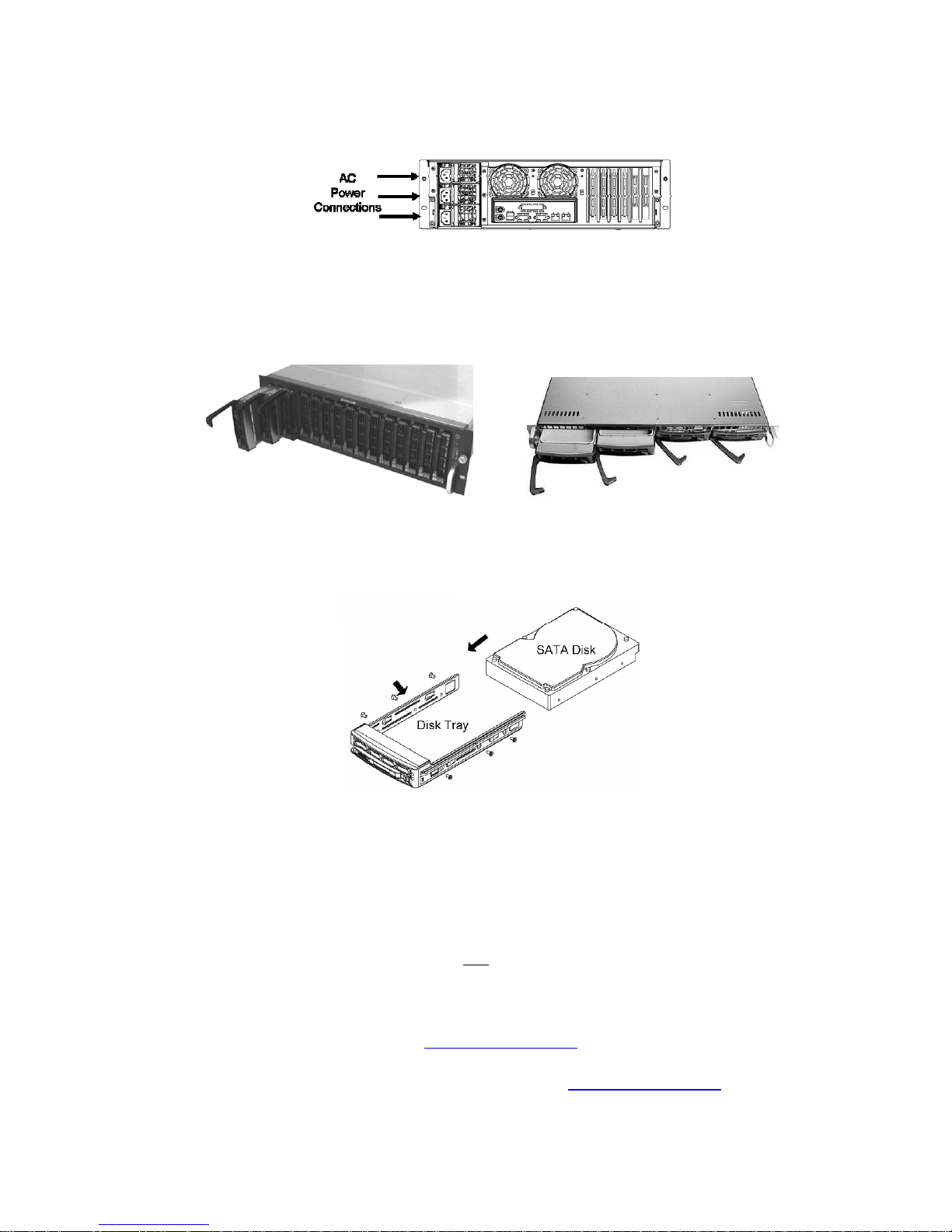
b. The power supplies in the shelf are auto sensing universal voltage (115/230VAC, 50/60Hz) and they come
with IEC connectors. The CED3U15SS shelf is supplied with three power cords for USA power systems.
(The CED1U4SS has one IEC power connection.) Other user supplied IEC adapter cords may be required
to meet power plug needs outside the USA.
c. After connection to an AC power source, press the power switch located on the front panel of the unit and
observe that the units fans are operational. The shelf is now ready for disks to be installed.
2. SATA Disk installation
a. EtherDrive® Storage is designed to accommodate standard 3.5” SATA disk drives. Press the colored
release tab located on the drive tray door to release the drive tray from its locking position and extend the
extraction handle to withdraw the drive tray.
b. (Note: Disk trays are initially supplied with a plastic blank where the disk is installed. This plastic blank also
provides an air flow restriction to slots that are not yet inhabited by disks. Do not remove the plastic blank
until you are ready to install a disk in its place, to maintain proper air flow within the shelf.) Remove the
plastic blank attached to the disk drive tray and install a SATA disk drive in its place using six screws
provided.
c. The disk and tray is now ready to be plugged into its slot in the shelf.
3. Shelf Address Configuration & Network Connection
a. IMPORTANT NOTE: Each shelf sharing a common Ethernet network must have a unique address to
prevent an address conflicting which may disrupt operation of other storage devices on the network
b. Connect a terminal to the serial com port on the back of the unit. (Com1 settings are 9600 N 1). Now refer
to the software manual for configuration setup.
c. CED3U15SS and CED1U4SS EtherDrive
the rear of the shelf. Use CAT6 Ethernet cable
d. Coraid recommends the use of Ethernet switches that support 802.3x (flow control). Most modern Ethernet
switches support these standards.
e. Install the latest AoE software driver on each Server that will be accessing the EtherDrive Storage. T his can
be downloaded from Coraid’s web site at
f. EtherDrive Storage is now ready and accessible by the network connected Servers, equipped with ATA-
over-Ethernet (AoE) drivers. Please consult the Coraid web site
“HOWTO” information.
Coraid Inc. Page 6
®
Storage appliances have two Gigabit Ethernet connections on
only to connect to a an Ethernet switch or Server.
www.coraid.com/support
www.coraid.com/support for helpful
Page 7

CAUTION !! – DO NOT SHIP PRODUCT WITH DISKS INSTALLED.
THIS MAY DAMAGE UNIT AND WILL VOID THE WARRANTY
Warranty and Return Policy
Coraid Inc. (“Coraid”) provides this Limited warranty to the entity that originally purchased the CORAID product.
Limited Warranty: CORAID warrants that the Hardware portion of the CORAID products described below will be free from material
defects in workmanship and materials from the date of original purchase of the product, for the period of thirty six (36) months
(“Warranty Period”)
CORAID’s sole obligation shall be to repair or replace the defective Hardware during the Warranty Period at no charge to the
original owner or to refund at CORAID’s sole discretion. Such repair or replacement will be rendered by CORAID at CORAID’s
Service Center. The replacement Hardware need not be new or have an identical make, model or part. CORAID may in its sole
discretion replace the defective Hardware (or any part thereof) with any reconditioned product that CORAID reasonably determines
is substantially equivalent (or superior) in all material respects to the defective Hardware. Repaired or replacement Hardware will be
warranted for the remainder of the original Warranty Period from the date of original retail purchase.
Limited Software Warranty: CORAID warrants that the software portion of the product (“Software”) will substantially conform to
CORAID’s then current functional specifications for the Software, from the date of original retail purchase of the Software for a
period of thirty six (36) months (“Warranty Period”).
Submitting A Claim: The customer shall return the product to the original purchase point based on its return policy. In case the
return policy period has expired and the product is within warranty, the customer shall submit a claim to CORAID as outlined below:
The customer must submit with the product as part of the claim a written description of the
Hardware defect or Software nonconformance in sufficient detail to allow CORAID to confirm the same.
1. The original product owner must obtain a Return Material Authorization (“RMA”) number from the CORAID Service
Center.
2. After an RMA number is issued, the defective product must be packaged securely in suitable shipping package to ensure
that it will not be damaged in transit, and the RMA number must be prominently marked on the outside of the package.
3. The customer is responsible for all in-bound shipping charges to CORAID. No Cash on Delivery (“COD”) is allowed.
Products sent COD will either be rejected by CORAID or become the property of CORAID. Products shall be fully insured
by the customer. CORAID will not be held responsible for any packages that are lost in transit to CORAID.
4. Return Merchandise Ship-To Address is Coraid Inc. 565 Research Dr., Athens, Georgia 30605
What Is Not Covered: This limited warranty provided by CORAID does not cover: Products, if in CORAID’s judgment, have been
subjected to abuse, accident, alteration, modification, tampering, negligence, misuse, faulty installation, lack of reasonable care,
repair or service in any way that is not contemplated in the documentation for the product, or if the model or MAC address has been
altered, tampered with, defaced or removed; Initial installation, installation and removal of the product for repair, and shipping costs;
Operational adjustments covered in the operating manual for the product, and normal maintenance; Damage that occurs in
shipment, due to act of God, failures due to power surge, and cosmetic damage; Any hardware, software, firmware or other
products or services provided by anyone other than CORAID; Repair by anyone other than CORAID or an Authorized CORAID
Service Center will void this Warranty.
Disclaimer of Other Warranties: EXCEPT FOR THE LIMITED WARRANTY SPECIFIED HEREIN, THE PRODUCT IS PROVIDED
“AS-IS” WITHOUT ANY WARRANTY OF ANY KIND WHATSOEVER INCLUDING, WITHOUT LIMITATION, ANY WARRANTY OF
MERCHANTABILITY, FITNESS FOR A PARTICULAR PURPOSE AND NON-INFRINGEMENT. IF ANY IMPLIED WARRANTY
CANNOT BE DISCLAIMED IN ANY TERRITORY WHERE A PRODUCT IS SOLD, THE DURATION OF SUCH IMPLIED
WARRANTY SHALL BE LIMITED TO NINETY (90) DAYS. EXCEPT AS EXPRESSLY COVERED UNDER THE LIMITED
WARRANTY PROVIDED HEREIN, THE ENTIRE RISK AS TO THE QUALITY, SELECTION AND PERFORMANCE OF THE
PRODUCT IS WITH THE PURCHASER OF THE PRODUCT.
Limitation of Liability: TO THE MAXIMUM EXTENT PERMITTED BY LAW, CORAID IS NOT LIABLE UNDER ANY CONTRACT,
NEGLIGENCE, STRICT LIABILITY OR OTHER LEGAL OR EQUITABLE THEORY FOR ANY LOSS OF USE OF THE PRODUCT,
INCONVENIENCE OR DAMAGES OF ANY CHARACTER, WHETHER DIRECT, SPECIAL, INCIDENTAL OR CONSEQUENTIAL
(INCLUDING, BUT NOT LIMITED TO, DAMAGES FOR LOSS OF GOODWILL, LOSS OF REVENUE OR PROFIT, WORK
STOPPAGE, COMPUTER FAILURE OR MALFUNCTION, FAILURE OF OTHER EQUIPMENT OR COMPUTER PROGRAMS TO
WHICH CORAID’S PRODUCT IS CONNECTED WITH, LOSS OF INFORMATION OR DATA CONTAINED IN, STORED ON, OR
INTEGRATED WITH ANY PRODUCT RETURNED TO CORAID FOR WARRANTY SERVICE) RESULTING F ROM THE USE OF
THE PRODUCT, RELATING TO WARRANTY SERVICE, OR ARISING OUT OF AN Y BREACH OF THIS LIMITED WARRANTY,
EVEN IF CORAID HAS BEEN ADVISED OF THE POSSIBILITY OF SUCH DAMAGES. THE SOLE REMEDY FOR A BREACH OF
THE FOREGOING LIMITED WARRANTY IS REPAIR, REPLACEMENT OR REFUND OF THE DEFECTIVE OR NONCONFORMING PRODUCT. THE MAXIMUM LIABILITY OF CORAID UNDER THIS WARRANTY IS LIMITED TO THE PURCHASE
PRICE OF THE PRODUCT COVERED BY THE WARRANTY. THE FOREGOING EXPRESS WRITTEN WARRANTIES AND
REMEDIES ARE EXCLUSIVE AND ARE IN LIEU OF ANY OTHER WARRANTIES OR REMEDIES, EXPRESS, IMPLIED OR
STATUTORY
Governing Law: This Limited Warranty shall be governed by the laws of the State of Georgia. Some states do not allow exclusion
or limitation of incidental or consequential damages, or limitations on how long an implied warranty lasts, so the foregoing limitations
and exclusions may not apply. This limited warranty provides specific legal rights and the product owner may also have other rights
which vary from state to state.
Copyright Statement: No part of this documentation accompanying this Product may be reproduced in any form or by any means
without permission from CORAID as stipulated by the United States Copyright. Copyright © 2003 by CORAID Inc. All rights
reserved. Trademarks: EtherDrive is a registered trademark of CORAID Inc.
FCC: This equipment has been tested and found to comply with the limits for a Class A digital device, pursuant to part 15 of the
FCC Rules.
Coraid Inc. Page 7
 Loading...