

Page 1
HA−6400
Côr Home Automation Panel
Advanced Installation Instructions
.C
1
..
.I
Page 2

About navigating this electronic document:
Throughout this document there are navigational links.
Wherever you see this symbol
...C.... you can click on it to return to the table of contents.
Wherever you see this symbol
Wherever you see underlined blue text
Whenever you navigate to a new page, you can go back using Alt +
..... you can click on it to return to the index.
...... I
you can click on it to navigate to that reference.
(left arrow)
CONTENTS
WELCOME! 7........................................................................
Features & Benefits 7..................................................................
INCLUDED IN BOX 8..................................................................
Optional Accessories 8.................................................................
Front of CôrPanel 9.................................................................
Back of CôrPanel 10.................................................................
1 HARDWARE INSTALLATION 11.......................................................
What You Need 11....................................................................
Choose a Location 11..................................................................
1.1 Install the Battery 12...............................................................
1.2 Connect Power Lead to Panel 12......................................................
1.3 Install Côr Panel 12..............................................................
1.4 Connect Power 13.................................................................
2 SET UP CONNECTIONS 14...........................................................
2.1 Select a Permanent Connection Mode 14...............................................
2.2 Ethernet Setup 15.................................................................
2.3 Check Ethernet Connection to CôrApp 16.............................................
2.4 Option 2 Wi−Fi Setup 17............................................................
2.5 Set Up a Web Access Passcode for CôrApp 19.........................................
2.6 Scan for Wireless Networks 19.......................................................
2.7 Troubleshooting Wi Fi Setup 21......................................................
2.8 Check Wi Fi connection to Côr Panel 22..............................................
3 THE COR
SMART HOME APP 23..................................................
3.1 Install Côr App 23...............................................................
3.2 Using the App 24..................................................................
3.3 Troubleshooting Setup 28...........................................................
4 SYSTEM SETTINGS 29..............................................................
4.1 Learn Sensors into CôrHub 29......................................................
4.2 Learn in a Keyfob 34...............................................................
4.3 Programming Areas 37.............................................................
4.4 Programming the System 39.........................................................
4.5 Programming Channels 42...........................................................
4.6 Programming the Network 44........................................................
4.7 Programming Scenes 47.............................................................
4.8 Programming Schedules 50..........................................................
.C.
2
..
.I
Page 3

4.9 Programming Holidays 52...........................................................
4.10 Programming Z−Wave Devices 54...................................................
Z−Wave Room Names 54..............................................................
Add a Z−Wave Device 54..............................................................
Z−Wave Device Association 55..........................................................
Z−Wave Maintenance 55...............................................................
4.11 Programming Cameras 57..........................................................
4.12 Check Event History 63............................................................
4.13 Check Connection Status 64........................................................
4.14 Check Details 64.................................................................
5 ADVANCED INSTALLATION USING WEB SERVER 65.................................
5.1 Advanced Programming, System 66...................................................
5.2 Advanced Programming, Sensors 75...................................................
5.3 Advanced Programming, Areas 79....................................................
Notes on Force Arming, Bypass, and Auto−Bypass 81........................................
5.4 Advanced Programming, Channels 87..................................................
Configure Email Reporting 89...........................................................
5.5 Advanced Programming, Communicator 90.............................................
5.6 Advanced Programming, Schedules 96.................................................
5.7 Advanced Programming, Actions 98...................................................
5.8 Advanced Programming, Arm−Disarm 103.............................................
5.9 Advanced Programming, Devices 105..................................................
5.10 Advanced Programming, Permissions 109.............................................
5.11 Advanced Programming, Area Groups 113.............................................
5.12 Advanced Programming, Menus 114..................................................
5.13 Advanced Programming, Holidays 115................................................
5.14 Advanced Programming, Sensor Types 116............................................
Sensor Types Table 119................................................................
5.15 Advanced Programming, Sensor Options 120...........................................
Sensor Options Table 123..............................................................
5.16 Advanced Programming, Event Lists 124..............................................
5.17 Advanced Programming, Channel Groups 125..........................................
Customize Reporting Codes 127.........................................................
Reporting Fixed Codes in Contact I.D. 129.................................................
5.18 Advanced Programming, Scenes 130.................................................
5.19 Advanced Programming, Speech Tokens 132...........................................
5.20 Advanced Programming, Cameras 134................................................
Add a Camera Method – Manual Entry 134................................................
Removing a Camera 134...............................................................
5.21 Advanced Programming, CôrHome Automation 142...................................
6 USERS AND PERMISSIONS 143−145...................................................
6.1 Add Users 143....................................................................
6.2 Users Submenus 145...............................................................
.C
3
..
.I
Page 4

6.3 Permissions 146...................................................................
7 CELLULAR RADIO SETUP 150−154...................................................
7.1 Install Optional Cellular Radio 150....................................................
7.2 Connect Power 151................................................................
7.3 Check Signal Strength 151...........................................................
7.4 Install External Antenna – Optional 152................................................
7.5 Check Cellular Connection to Côr App 154...........................................
8 CAMERA SETUP INSTRUCTIONS 156−166.............................................
8.1 Quick Setup 156...................................................................
8.2 Setting up Ethernet/Wi Fi transmission 156..............................................
8.3 Wi Fi Signal Strength 157...........................................................
8.4 Add Camera via Wi Fi for iOS Device 158..............................................
8.5 Add Camera via Wi Fi for Windows PC 158.............................................
8.6 Add Camera via Ethernet for iOS Device (non DHCP) 159.................................
8.7 Add Camera via Ethernet for Windows PC (non DHCP) 160................................
8.8 Add Camera via Ethernet (DHCP) 160.................................................
8.9 Add Camera to CôrApp 161........................................................
8.10 View Live Stream and Latest Clip 162................................................
8.11 Program event triggered camera clips 162..............................................
8.12 View event triggered clips in History 164..............................................
Remove Camera from Côr (if needed) 165...............................................
8.13 Change Default Camera Settings (Via TruVision Navigator) 165............................
8.14 Camera Troubleshooting 166........................................................
9 INSTALLATION USING KEYPAD 167−173..............................................
9.1 Basic Installation 167...............................................................
9.2 Learning Sensors into Côr 167......................................................
Sensor Types Presets 167...............................................................
9.3 Configure Sensor Names (optional) 168................................................
9.4 Record Sensor Names (optional) 170..................................................
9.5 Test Sensor Signal Strength 170......................................................
9.6 Remove a Sensor 171...............................................................
9.7 Change the User Type (optional) 171..................................................
9.8 Add a User / Keyfob 171............................................................
9.9 Record User Names (optional) 172....................................................
9.10 Remove a User 172...............................................................
9.11 Add a Keyfob 173................................................................
9.12 Remove a Keyfob 173.............................................................
PERSONALIZE YOUR CÔRPANEL 173−179............................................
9.13 Volume Level 173................................................................
9.14 Voice Annunciation 174............................................................
9.15 Full Menu Annunciation 174........................................................
9.16 Backlight Level 174...............................................................
9.17 Change Time and Date 175.........................................................
.C.
4
..
.I
Page 5

9.18 Adjust Area Entry or Exit Times 175..................................................
9.19 Reset Installer Account 176.........................................................
9.20 Reset to Factory Default (optional) 176................................................
9.21 Table Mount (Optional) 176.........................................................
9.22 Wall Tamper Option 177...........................................................
9.23 Connecting Inputs 177.............................................................
9.24 Connecting Outputs 179............................................................
10 TESTING THE SYSTEM 180−181....................................................
10.1 Perform a Walk Test 180...........................................................
10.2 Perform a Siren Test 180...........................................................
10.3 Perform a Battery Test 180.........................................................
10.4 Perform a Communicator Test 181...................................................
10.5 Event History 181................................................................
11 GLOSSARY 182.....................................................................
Appendices 185−200..................................................................
A.1 DLX900 Software 185.............................................................
A.2 Troubleshooting DLX900 187.......................................................
A.3 Firmware upgrade using DLX900 188.................................................
A.4 Firmware upgrade using USBUP 189..................................................
A.5 System Status Messages 190.........................................................
A.6 App and Web Error Messages 191....................................................
A.7 Z−Wave Messages 192.............................................................
A.8 History Events 193................................................................
Event ID Table 193...................................................................
A.9 Event Reporting Class Table 196.....................................................
A.10 Action Events: Category and Types 197...............................................
A.11 Action Results Category and Action Results Event Types 198..............................
A.12 CôrHub Building Blocks 199.....................................................
A.13 CôrHub Web Server Tree 200.....................................................
Specifications 201....................................................................
UL SPECIFICATION 202−207...........................................................
Electrical: 202.......................................................................
Software Version: 202.................................................................
Installation Notes: 202.................................................................
Compatible Receivers: 202.............................................................
Listings and Approvals: 203............................................................
Minimum System Configuration: 203.....................................................
Abort: 203..........................................................................
Quick exit: 203.......................................................................
Exit delay extension: 203...............................................................
Exit Progress Annunciation: 204.........................................................
Entry Progress Annunciation: 204........................................................
Keyfob operation / System Acknowledgement: 204..........................................
.C
5
..
.I
Page 6

Canceling and preventing accidental alarms: 204............................................
Recent Closing: 205...................................................................
Sensor Tripping Instructions: 205........................................................
SIA CP−01−2010 Programmable Features 206..............................................
Smoke and heat detector locations: 207....................................................
PRODUCT WARNINGS 208.............................................................
WARRANTY DISCLAIMERS 208.........................................................
Disclaimer 208.......................................................................
Intended Use 209.....................................................................
Copyright 209.......................................................................
Trademarks and Patents 209............................................................
Regulatory Notices for USA 209.........................................................
Regulatory Notices for Canada 210.......................................................
INDEX CLICK ON ENTRIES TO NAVIGATE 211..........................................
.C.
6
..
.I
Page 7

WELCOME!
Thank you for purchasing CôrHome Automation!
Please read through this document before starting the installation.
Features & Benefits
256 Users – enough for even moderate sized businesses
64 wireless sensors + 20 Keyfobs
4 Areas/Partitions – split your system into smaller parts you can protect individually
Personal Voice Guided setup and menu prompts
2 Hardwired inputs (can be doubled to total 4)
2 Programmable Outputs
85db piezo siren
24 hour battery backup
Wi Fi 802.11 b/g
Wi Fi direct for setup
IEEE 802.3 Compliant Ethernet
3G Cellular Radio Module, optional
.C
7
..
.I
Page 8
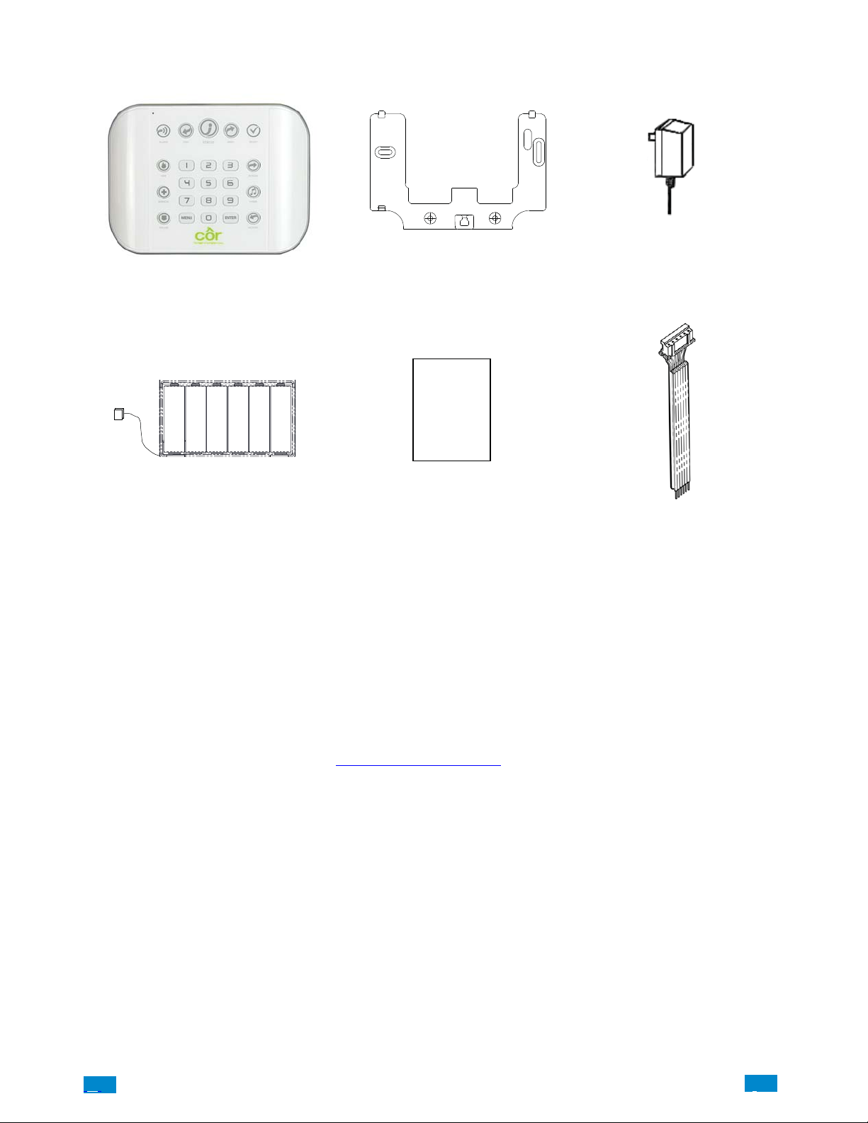
INCLUDED IN BOX
Check contents before beginning your installation.
Côr™ Panel
Transformer
Wall Bracket
Backup Baery Pack
Installaon
Manual
Full
Reference Guide
Available Online
Optional Accessories
Cellular Radio Modem ZW−HSPA
Desk Stand ZW−DS01
Extension Antenna ZW−ANT3M
Battery ZW−BAT23A
Power Supply ZW−PS9V
Ultra Secure IP Camera ZW−USW−3120
(Only works with Côr)
A list of available accessories is available online at www.CorHomeAutomation.com
Input/Output Lead
A160028
.
.C.
8
..
.I
Page 9
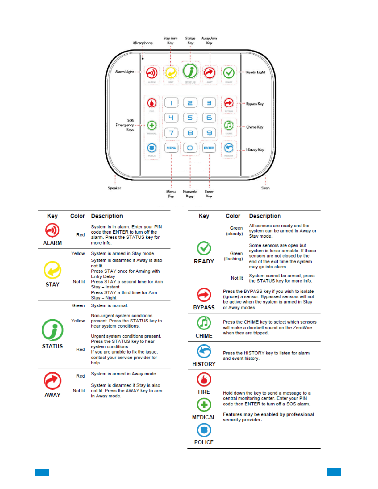
FRONT OF CÔR PANEL
.C
9
..
.I
Page 10
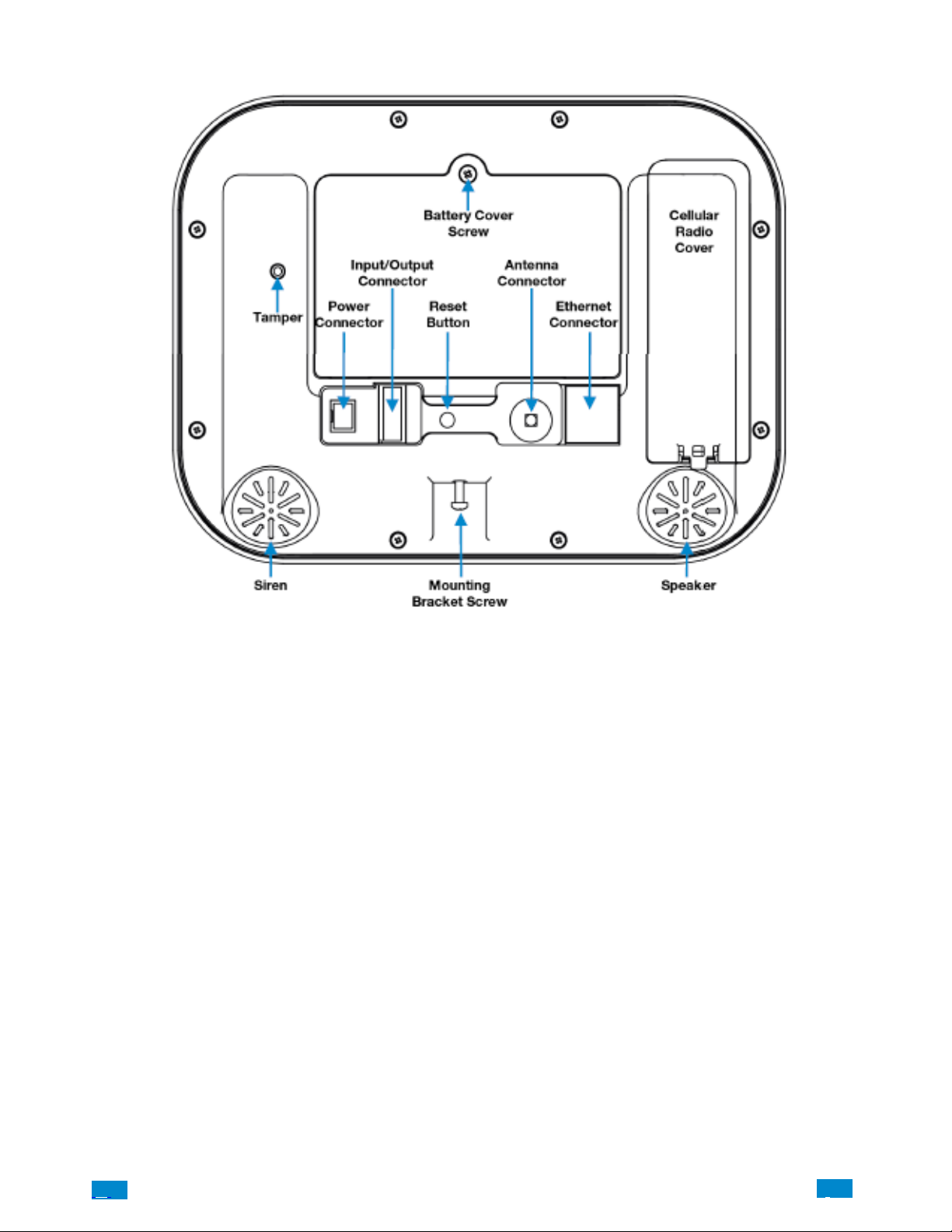
BACK OF CÔR PANEL
Connections for the cellular radio module are located under the cover on the right.
.C.
10
..
.I
Page 11

1 HARDWARE INSTALLATION
What You Need
Côr Panel
Côr Accessories (Door/Window sensors, Motion sensors, Lighting modules, Door Locks, etc.)
Devices, lights locks etc.)
A mobile or smart device, or computer for programming
List of homeowner users and PIN codes homeowner wish to add
Small Phillips screwdriver
Small Flathead screwdriver
Router supporting 802.11 b or 802.11g if using homeowner Wi Fi features
IP access for optional cell module
Wi Fi/Ethernet access
Choose a Location
When choosing a location for your Côr Panel there are a number of appliances and areas to avoid which could interfere with the security
system.
Choose a central location that optimizes signal strength (Wi Fi, 319.5, Z−Wave)
A void TV and other electronic appliances
A void microwave ovens
A void wet and moist areas such as bathrooms and toilets
A void cordless telephones
A void computers and wireless equipment
.C
11
..
.I
Page 12
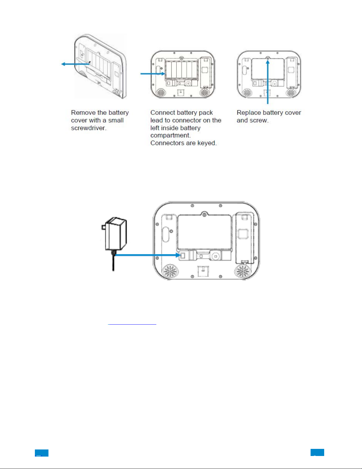
1.1 Install the Battery
1.2 Connect Power Lead to Panel
Connect power lead from power supply to the back of the panel. The connector is keyed and fits only one way.
1.3 Install Côr Panel
Panel may be mounted on a wall (recommended) or on a table.
For table mount information please reference Section 9.21
Install the bracket on a wall by using the supplied screws. Make sure the power lead can reach the panel when plugged in to a power source.
NOTE: Holes in the wall supplying Ethernet, power, antenna or I/O connector must be in the shaded area to ensure the unit mounts flat on
the wall; See the drawing on the next page.
.C.
12
..
.I
Page 13
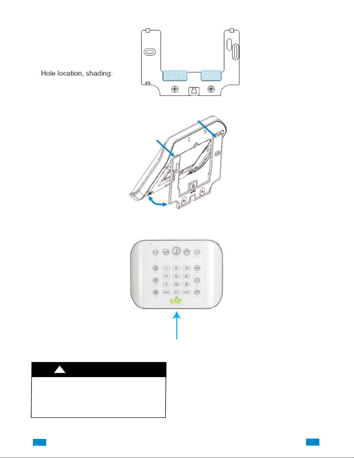
Align the Côr Panel with the top clips on the wall bracket, and then push the Côr Panel so it sits flat against the wall.
NOTE: Ensure the screw on the underside of the panel is loosened enough so that the wall bracket clears the screw head; if not the panel may
not fit flush against the wall. Then retighten the screw to ensure a secure fit.
1.4 Connect Power
Connect the power supply to receptacle.
!
WARNING
PERSONAL INJURY AND UNIT DAMAGE
HAZARD
Failure to follow this warning could result in personal
injury or death and unit component damage.
Do not connect to a receptacle controlled by a switch.
.C
13
A160088
..
.I
Page 14
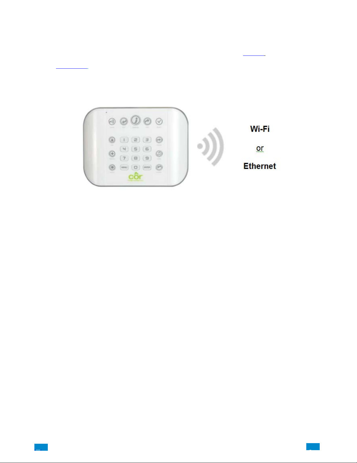
2 SET UP CONNECTIONS
2.1 Select a Permanent Connection Mode
Select a method to connect your Côr panel to a network so it can report events via Cloud, and allow you to configure settings using the
built−in Web Server or Côr app. The recommended installation for security monitoring is to use IP as primary reporting with cellular
backup. However IP only or cellular only installations may be used. For cellular radio setup reference Section 7.
Option 1 − Ethernet Setup – This is the easiest to set up. The Côr panel is set to use Ethernet by default. It requires a hardwired Ethernet
connection to the panel. You will need to provide an Ethernet router and an internet connection for reporting and remote access.
Option 2 − Wi Fi Setup − This connects the Côr to a local Wi Fi network. You will need to provide a wireless router and a secure internet
connection for reporting and remote access.
.C.
14
..
.I
Page 15
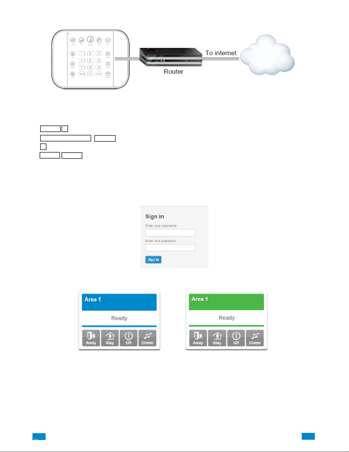
2.2 Ethernet Setup
Connect power to your Côr panel.
If this panel was previously connected via Wi Fi, switch connection to Ethernet:
MENU
1.
2.
INSTALLER CODE
3.
7
4.
MENU
Connect an Ethernet cable to the rear of the panel and wait 10 sec for the local router to assign the panel an IP address.
On the panel press Menu – 8 – [PIN] – 6 and note the IP address announced. This is the IP address of your Côr panel. If you hear “IP
address is not ready” then wait a further 30s and repeat this step. Open your web browser. Enter IP addr ess (For example:192.168.1.6). The
Côr login screen should appear:
Enter your username and password. By default this is : installer and 9 7 1 3.
You should now see a screen similar to one of the below.:
9
MENU
ENTER
Select main menu - Option 9, Advanced system conguration
Enter Installer code (By default thisis 9 7 1 3)
Toggles between WiFi or Ethernet connection unit Ethernet is on
Exits from Advanced system conguration menu
A160042
Your Côr panel is now successfully connected to your Ethernet network.
.C
15
..
.I
Page 16
2.3 Check Ethernet Connection to CôrApp
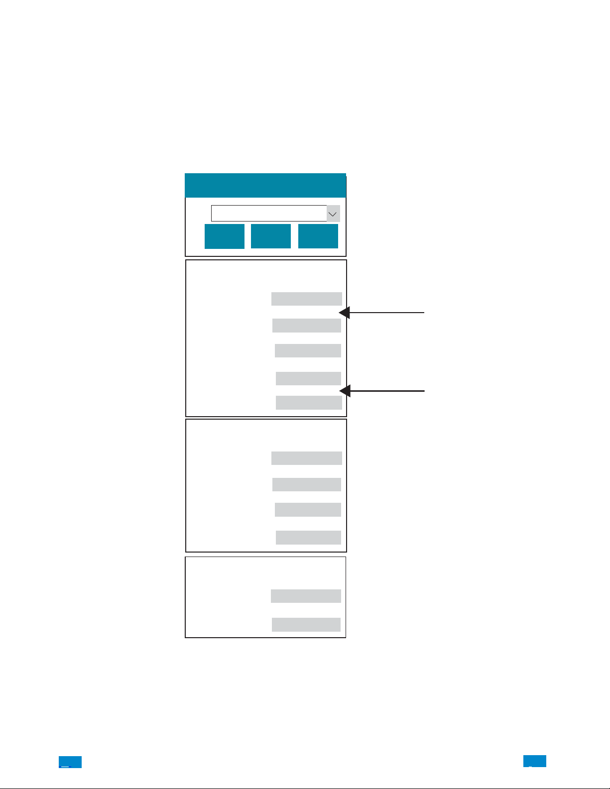
Login to the Côr Web Server from your laptop using the IP address announced. Press or click Settings.
Select Connection Status in the drop down menu.
Check that:
a. LAN Status should display Connected.
b. LAN Media should display Ethernet.
c. UltraSync−Status should display Connected.
d. UltraSync−Media should display LAN.
Settings Selector
Connection Status
Up
Down
Connection Status
LAN Status
LAN Media
Cell State
UltraSync Status
UltraSync Media
Radio Details
Cell Service
Signal Strength
Operator ID
Reload
Connected
Ethernet
Idle
Connected
LAN
No service
0
If it does not:
e. Check cable connection.
f. Check router settings.
.C.
Radio Technology
WiFi Details
WiFi SSID
WiFi Security Type
GSM
None
16
..
.I
A160043
Page 17
2.4 Option 2 − Wi Fi Setup
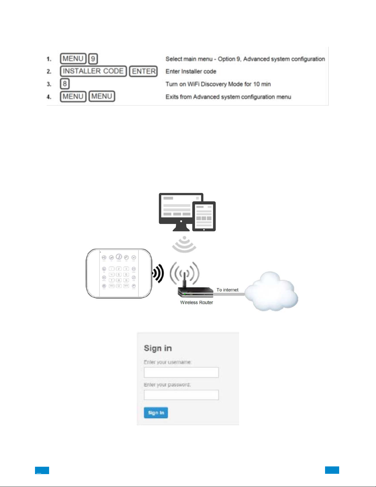
Turn on Wi Fi Discovery Mode − this creates a local hot spot and provides direct access to the Côr panel from a mobile device such as a
tablet, or laptop computer.
Enable Wi Fi on your tablet or laptop computer.
On your mobile device, browse for available Wi Fi networks and select the ZeroWire_xxxx network to connect to it.
NOTE: Note: Only a single user can connect at any time and there is no Wi Fi password.
Once connected, the Côr will be assigned a fixed IP address of 192.168.1.3.
Use your tablet or laptop computer to connect to Côr.
NOTE: Note: The wireless router must support 802.11 b or 802.11g.
Open your web browser and enter 192.168.1.3. The Côr. login screen should appear.
Enter your username and password, by default this is: installer and 9 7 1 3.
Press Sign In.
.C
17
..
.I
Page 18
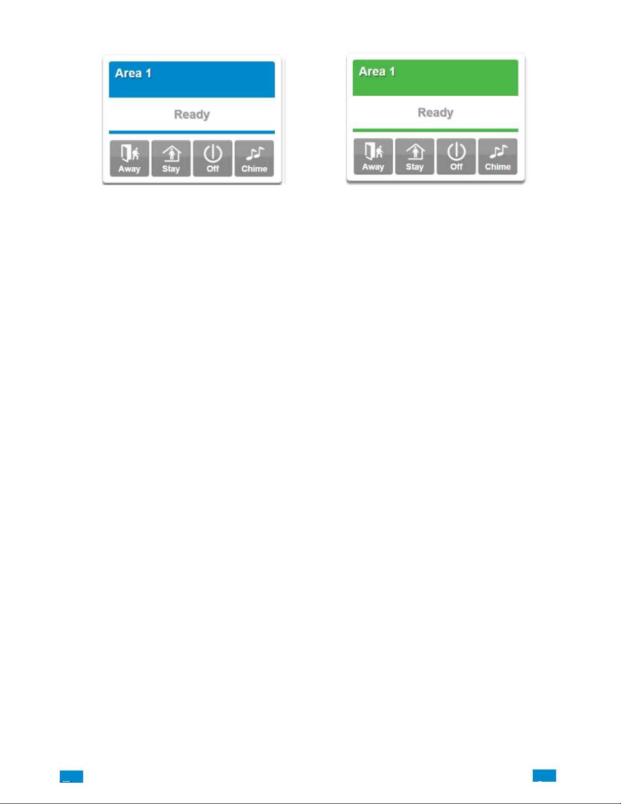
You should now see a screen similar to one of the below:
Your Côr is now successfully connected to your Wi Fi network.
.C.
18
..
.I
Page 19
2.5 Set Up a Web Access Passcode for CôrApp
For security, initial remote access via the Côr app is disabled by default. Follow these steps to enable it:
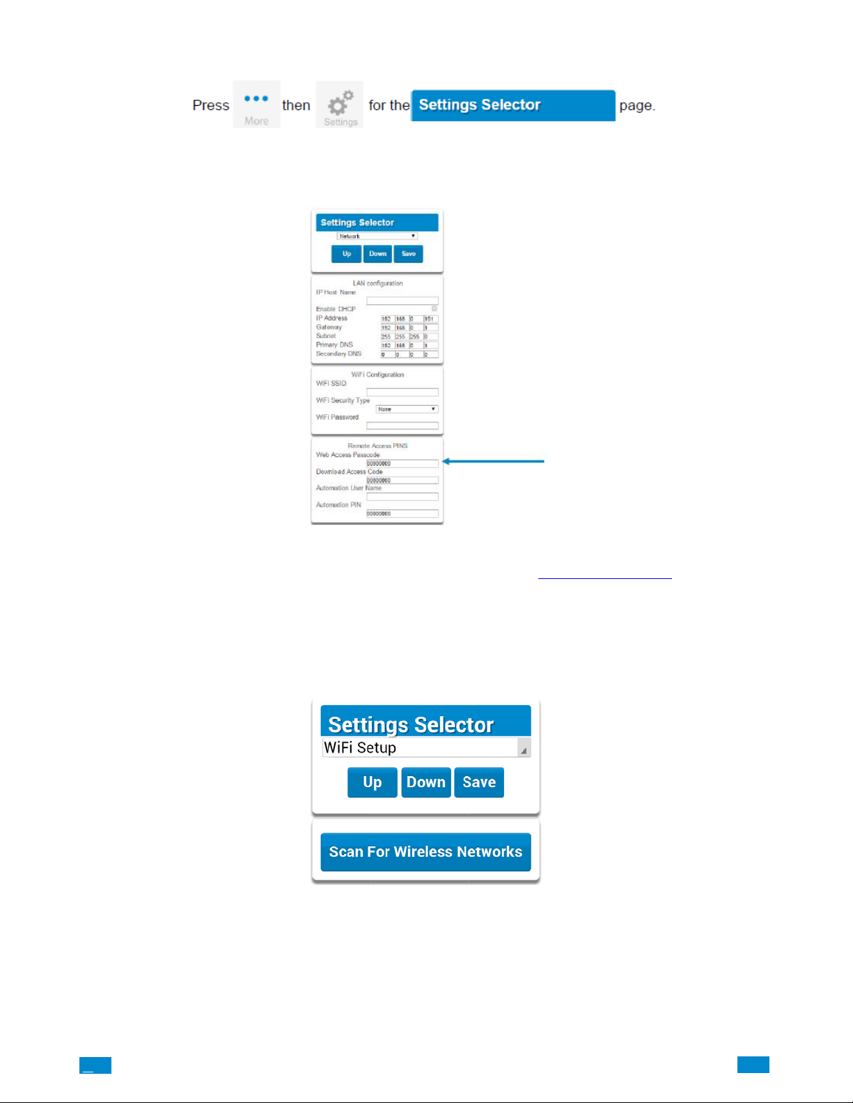
Select Network from the drop down menu. Enable remote access for the Côr App by changing the Web Access Passcode (WAP) with a
unique eight digit code provided by the homeowner. This is an eight digit code that permits the homeowner remote access from their Côr
mobile app. The default Web Access Passcode of 00000000 prevents remote access.
NOTE: If you are connecting to the system via the Local Area Network (LAN) the WAP is not required.
Press Save. “Program Success” will appear.
For a detailed explanation of the function of the Web Access Passcode please see section 4.6 Programming the Network
2.6 Scan for Wireless Networks
Press Settings
Select Wi Fi Setup form the drop down menu.
Press Scan for Wireless Networks:
.
.C
19
..
.I
Page 20
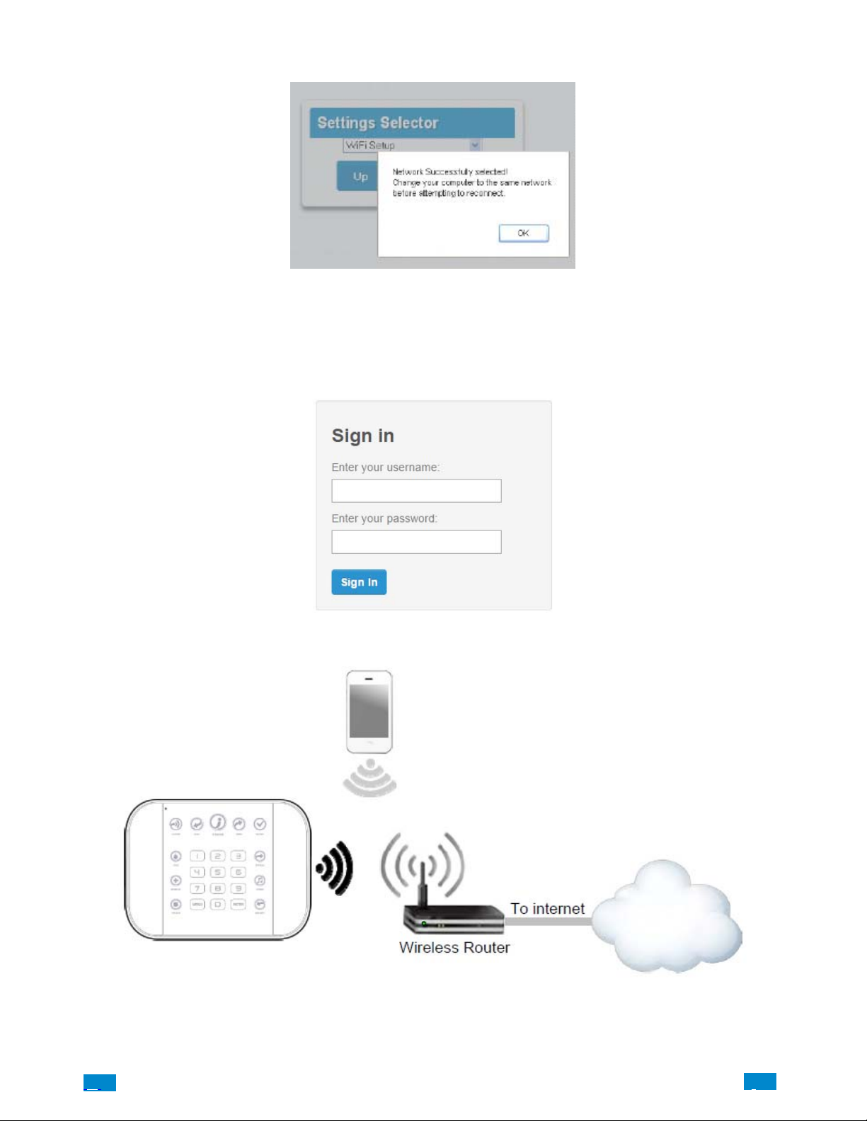
Press the Wi Fi network name you wish Côr panel to connect to. Enter Wi Fi passcode then press OK. “Network Successfully selected” will
appear as shown below. Upon connection to the Wi Fi network, the system will automatically logoff from the web browser.
On your mobile device, connect to the same Wi Fi network found by the scan.
On the panel press Menu – 8 – [PIN] – 6 and write down the IP address announced. This is the IP address of your Côr panel. If you hear
“IP address is not ready” then wait a further 30 seconds and repeat this step.
Open your web browser.
Enter announced IP address. The login screen should appear:
Your Côr panel is now successfully connected to your Wi Fi network.
.C.
20
..
.I
Page 21
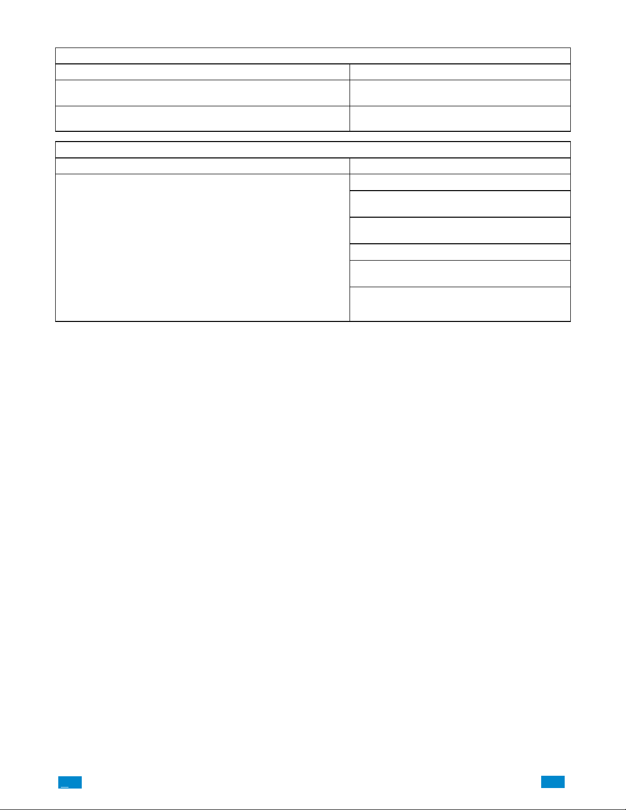
2.7 Troubleshooting Wi Fi Setup
1. Cannot get an IP address
Cause Solution
Connection does not work
The wireless/router may not be configured for automatic DHCP or cer-
tain security settings may be enabled.
2. Network connections fail
Cause Solution
Some newer routers will have these off at factory default. Some
802.11n access points may not accept 802.11g connections
Close the web browser on your device, and restart
your wireless router, and start again from step 1.
Check your router settings and try again.
Check if Wi Fi router allows b and g connections.
Check if router is within range and has good signal,
otherwise a Wi Fi range extender may help.
Ensure auto−correct is turned off (when typing the
Wi Fi pass phrase).
Ensure wireless router has DHCP enabled.
Ensure wireless router does not have firewall or se-
curity rules that prevent additional connections.
Ensure IP addresses are available; for example con-
nect a new device to it and verify it has an internet
connection.
.C
21
..
.I
Page 22
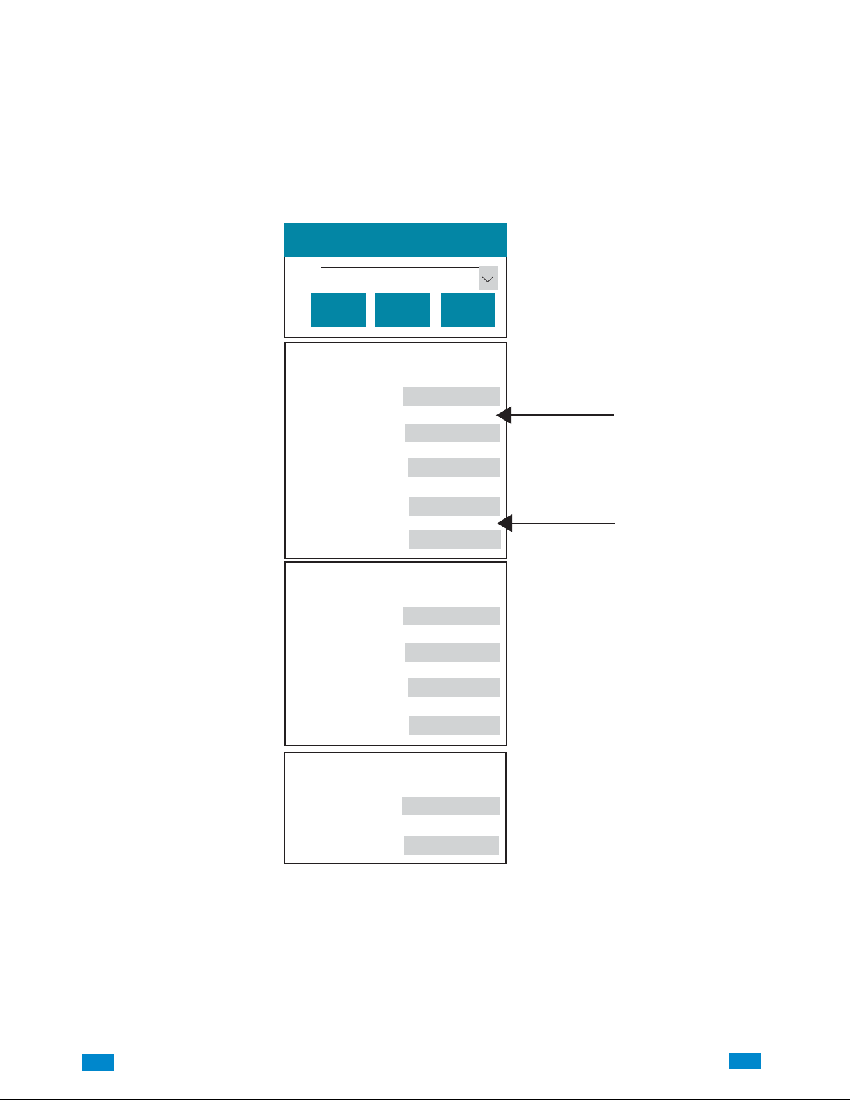
2.8 Check Wi Fi Connection to Côr Panel
Login to the Web Server from your computer using the IP address announced which can be obtained by pressing Menu 8 − [Installer PIN]
− 6 on the Côrpanel. Press Settings in the drop down Menu at the top right.
Select or press Connection Status in the drop down menu.
Check that
a. LAN Status should display Connected.
b. LAN Media should display Wi Fi.
c. UltraSync−Status should display Connected.
d. UltraSync−Media should display LAN.
Settings Selector
Connection Status
Up
Down
Connection Status
LAN Status
LAN Media
Cell State
UltraSync Status
UltraSync Media
Radio Details
Cell Service
Signal Strength
Operator ID
Radio Technology
Reload
Connected
Wi Fi
Idle
Connected
LAN
No service
0
GSM
If it does not
e. Check cable connection.
f. Check router settings.
.C.
WiFi Details
WiFi SSID
WiFi Security Type
None
22
..
.I
A160046
Page 23
3 THE CôrAPP
A160067
3.1 Install CôrApp
The Côr Smart Home is an app that allows you to control your Côr Home Automation System from an Apple iPhone/iPad, or Google
Android device. First set up the Côr Web Server from Section 2 then download this app.
Carrier charges may apply and an Apple iTunes or Google account is required.
On Apple devices go to the App Store. On Android devices go to the Google Play store.
Search for Cor Home Automation.
Install the app for the Homeowner.
Press the icon on your device to launch it.
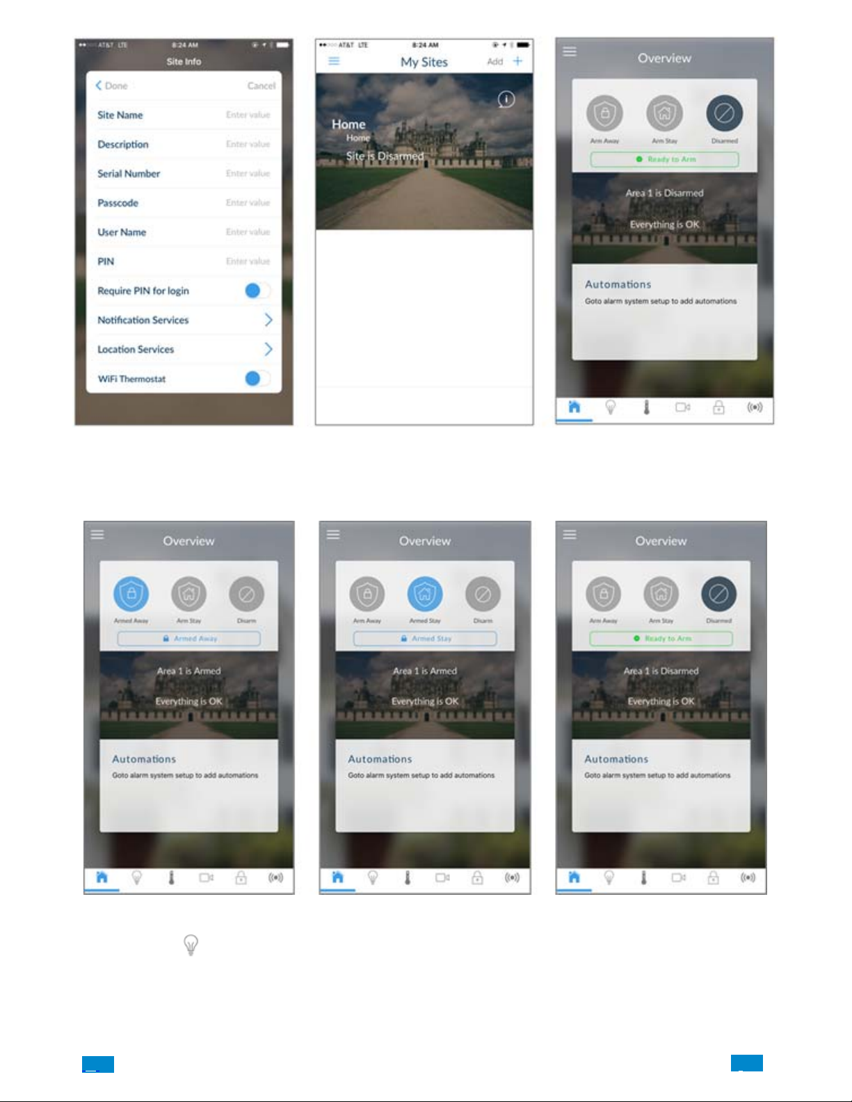
Press Add or + on the top right to add a new Site or the information callout icon to edit an existing Site.
Enter the information for the Site Name and Description that the homeowner wants to use.
The Serial Number is printed on the back of the panel.
The default Web Access Passcode of 00000000 disables remote access. To change it, login to Côr Web Server and go to Settings −
Network. (Refer to Section 2.3.)
The default username and PIN code for the master user is User 1 and 1234. You may also use any other valid user account. Homeowner users
will only see and have access to menus at their permission level.
Toggle the blue slider to the right if the homeowner wants to require a PIN for login.
The Notification Services will allow the user to receive notifications in the event of a triggered event. To enable this function, tap on the arrow
and toggle the blue slider to the right to activate Push Notificaitons.
The Location Services will allow actions based on entering and exiting specific map areas using global positioning system (GPS) location of
the user phone. To enable this function, tap on the arrow and toggle the blue slider to the right to activate GEO Actions and/or Check Status
on Leaving.
Compatible Wi Fi thermostat from Carrier and Bryant can be added to the app by toggling the blue slider. The following screen will ask the
user to login to their registered thermostat account and agree to the terms to authorize app access to the thermostat control.
Press Done button to save the details and to go back.
Press the name of the Site to enter the main Overview screen of the Côr Home Automation system app.
.C
23
..
.I
Page 24
3.2 Using the App
The first screen that will appear once you connect is the Overview screen. This will display the status of your system and allows you to arm
or disarm areas by pressing Arm Away, Arm Stay, or Disarm. From this screen, you can also enable Automations that have been
programmed in the Côr app.
The menu bar is located along the bottom of the screen.
Press the Lights icon
and on/off appliances. Please see Section 4.10 for Programming Z−Wave Devices. From this screen, you are able to dim or turn on/off light
switches; and turn on/off power to plugged−in appliances or products. In addition, you can use the Automation feature to program your Côr
Home Automation system to turn on these Z−Wave enabled modules and outlets at a certain time; or set up lights to turn on and off to mimic
occupancy while you are away from your home.
.C.
to access Z−W ave enabled modules and outlets that are connected to the Côr Home Automation system for lighting
24
..
.I
Page 25
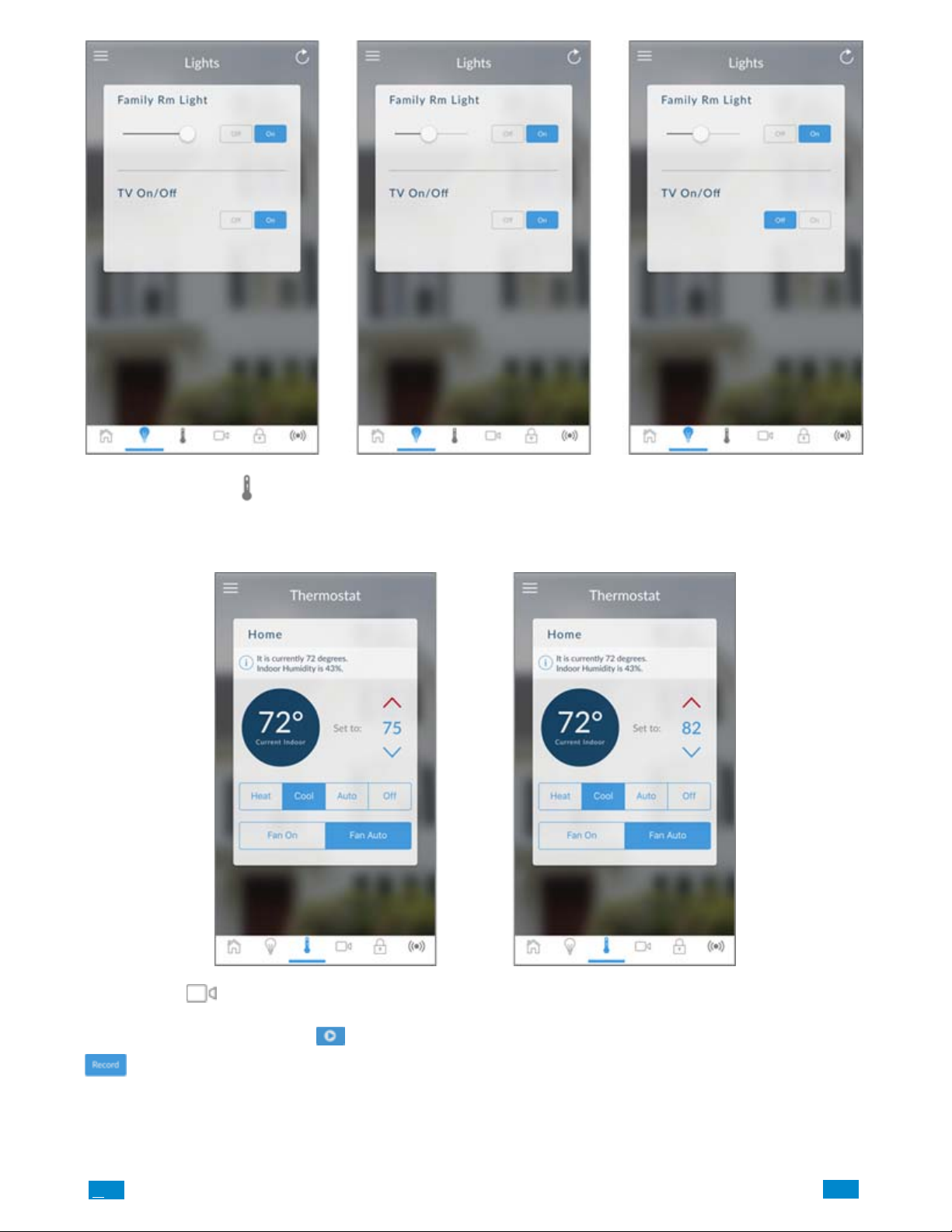
Press the thermometer icon at the bottom of the menu bar to control your thermostats that are connected to your Côr Home Automation
system. Using the red and blue arrow to the right of the screen, you can adjust your desired temperature setting to maintain comfort in your
home. This screen also allows you to change the operational mode of your heating and air conditioning system by selecting either Heat,
Cool, Auto or Off. In addition, you can control the fan operation either to run constantly On or in the Auto mode.
Press camera icon at the bottom of the menu bar to access the Wi−Fi cameras connected to the Côr Home Automation system. Pressing
the Play icon in the center picture of the video will allow you to view live video streams from the camera. You can also view previously
recorded clips by pressing the Play icon
button to initiate the camera into recording mode.
.C
under Latest Clip section of the screen. Or if you want to record a video, press the Record
25
..
.I
Page 26
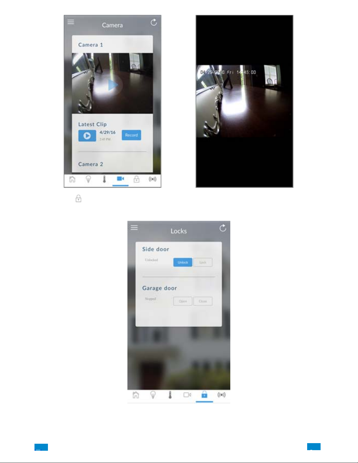
Press the Lock icon at the bottom of the menu bar to access Z−Wave enabled open and close devices such as Door Locks and Garage
Door Openers. On this screen, you can check the status of a Z−Wave enabled door lock or garage door; and remotely lock the door or close
the garage door.
.C.
26
..
.I
Page 27
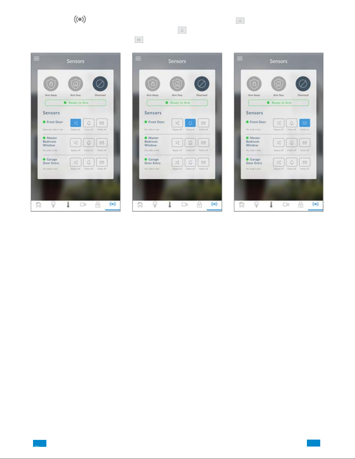
Press Sensors icon to view sensor status. From the Sensors screen you can press Bypass to ignore a sensor or press it again to
restore it to normal operation. You may also turn on or off the Chime
triggered then press the sensor Notification icon
to turn on or off.
feature. If you would like to be notified when a specific sensor is
.C
27
..
.I
Page 28
3.3 Troubleshooting Setup
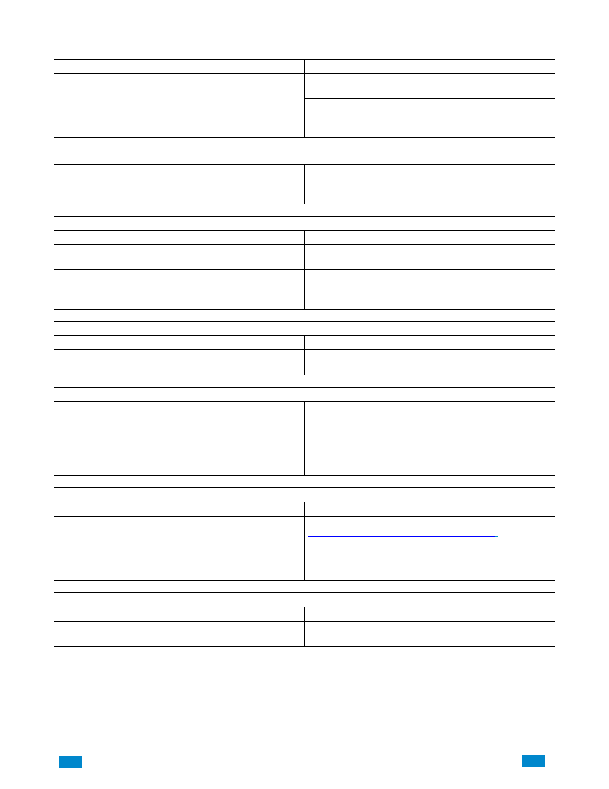
1. Site Creation fails
Cause Solution
Check the serial number and web access passcode, match those
in the Côr W eb Server set−up.
Settings are entered incorrectly
2. Cannot see local Wi Fi access point from smartphone
Cause Solution
Some hotspot access points may not accept 802.11g connections. Ensure your Wi Fi access point is able to accept 802.11b or
3. Network connections fail
Cause Solution
Ethernet not working
Wi Fi not working If connected by Wi Fi, check that the connection is working.
Network not set
Web Access Passcode must not be 00000000.
User Name must be entered with a space between the first and
last name and with correct capitalization.
802.11g.
If connected by Ethernet, check that the cable is plugged in and
the connection is working.
Check Settings − Network − Enable UltraConnect is checked
under Options.
4. Cannot get IP address
Cause Solution
The wireless/router may not be configured for automatic DHCP
or certain security settings may be enabled.
5. Cannot access internet
Cause Solution
Mobile device has no access
6. Server connections fail
Cause Solution
Server addresses are incorr ect
7. Configuration setting changes fail
Cause Solution
Devices are not responding to inputs
Check your router settings and try again.
Open a web browser on your mobile device to double check
access.
T ry disabling Wi Fi on your device once the Côr panel is con-
figured and using the 3G/4G data connection of the homeowner
smartphone with the Côr app.
Check the UltraSync servers are correct. See
Advanced Programming, Cor Home Automation for reference.
a. Ethernet Server 1 − zw1.UltraSync.com:443
b. Ethernet Server 2 − zw1.UltraSync.com:443
c. Wireless Server 1 − zw1w.UltraSync.com:8081
d. Wireless Server 2 − zw1w.UltraSync.com:8081
Re−initialize equipment. Power cycle connected equipment including Côr Hub and customer supplied router(s).
.C.
28
..
.I
Page 29
4 SYSTEM SETTINGS
These instructions describe how to program all of the devices, schedules and areas used by the system.
4.1 Learn Sensors into CôrHub
Connect to the Côr Web Server (either via Wi Fi Discovery Mode or Ethernet Setup.
Enter your username and password. By default this is installer and 9713.
Press Sign In.
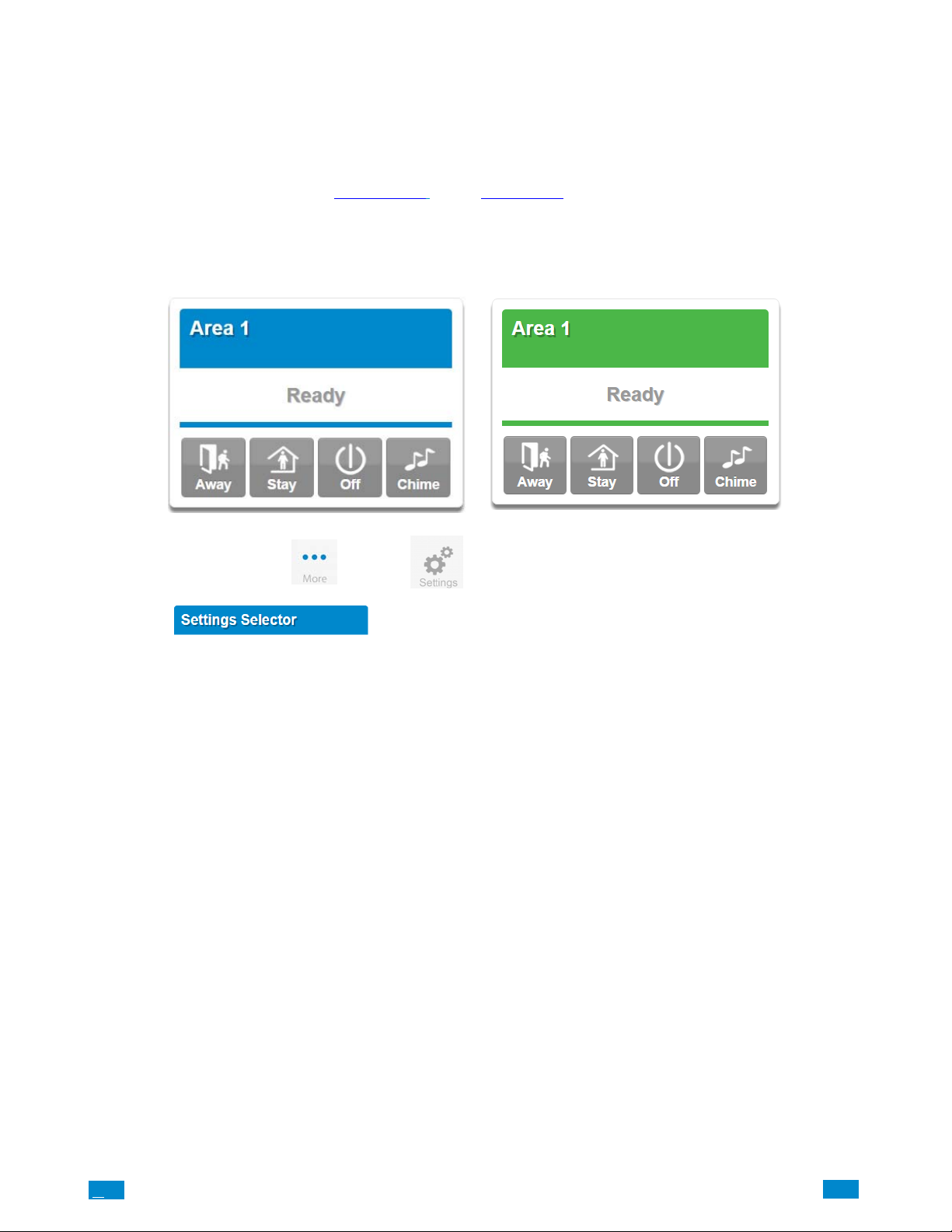
You should see a screen similar to one of the below:
From the Côr screen app press the button then .
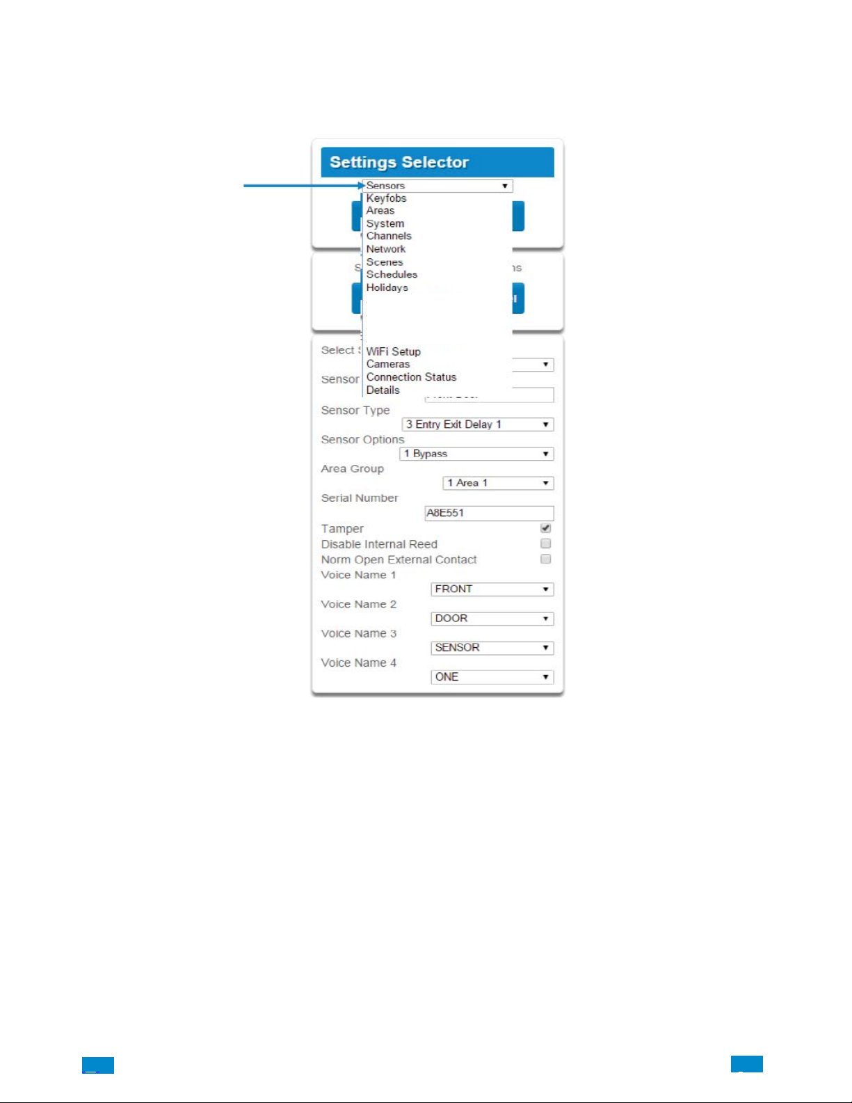
You are on the
Select the drop down menu under Sensors to see the list of programmable items.
Select Sensors.
page.
.C
29
..
.I
Page 30
Z-Wave Room Names
Z-Wave Add/Remove
Z-Wave Device Association
Z-Wave Maintenance
A160049
At this point you can type the name of the sensor and define its profile, by determining the sensor type (Entry, 24 hour, fire, key switch, etc.)
and the sensor options (bypass, force arm, Cross Zone, stay mode, etc.). You can also assign it a specific area. Each of these has a drop down
menu to make selections.
.C.
30
..
.I
Page 31
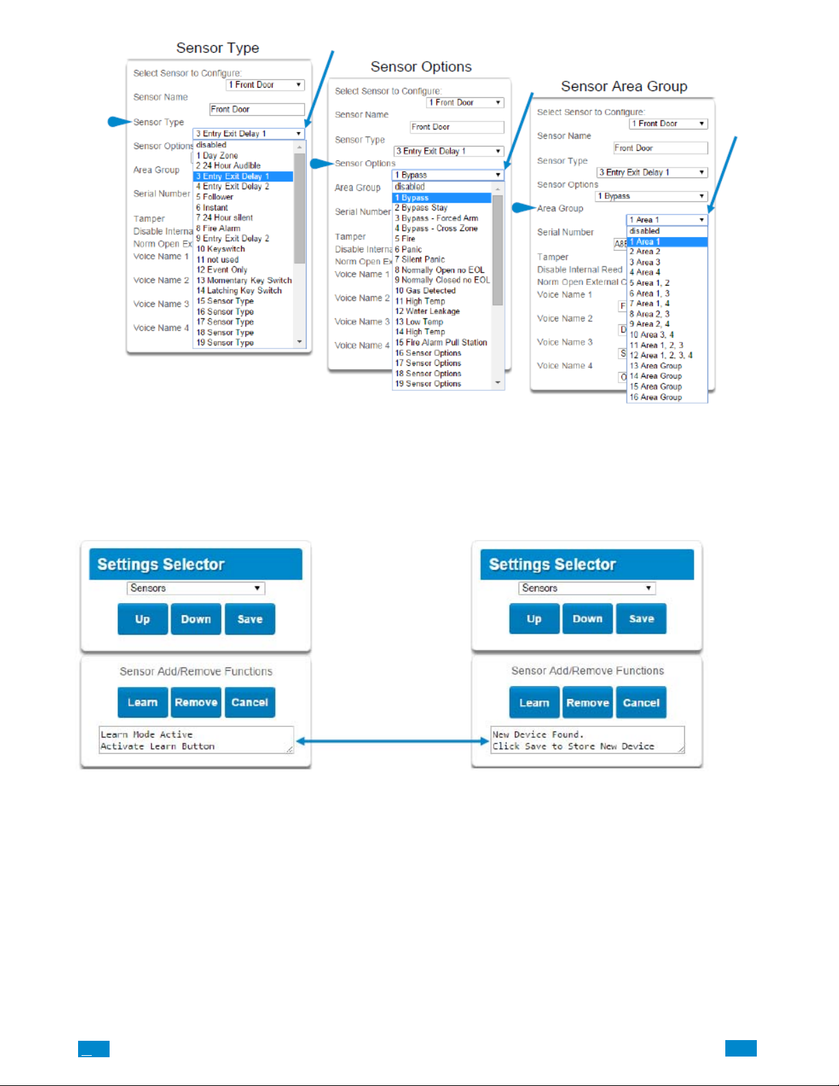
When all of your programming definition for the sensor is complete, press Learn. A notification box will appear below the Learn button.
Activate the sensor. Consult the sensor manual for instructions; generally this is performed by opening the case and manipulating the tamper
activator. This will send a tamper signal to the Côr panel. The notification box will alert you that a new device was found.
.C
31
..
.I
Page 32
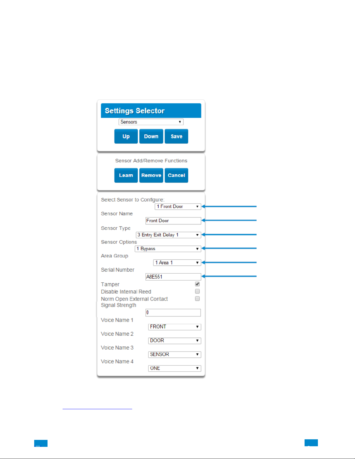
The screen below shows a sensor learned in.
Name: Front Door
Type: Entry Exit Delay 1
Option: Bypass
Area Group: Area 1
Serial Number: A8E551
Note that the sensor Serial Number box has been populated after learning in the sensor.
Explanations of the sensor configurations appear on the next page.
Also reference Advanced Programming, Sensors, Section 5.2.
.C.
32
..
.I
Page 33
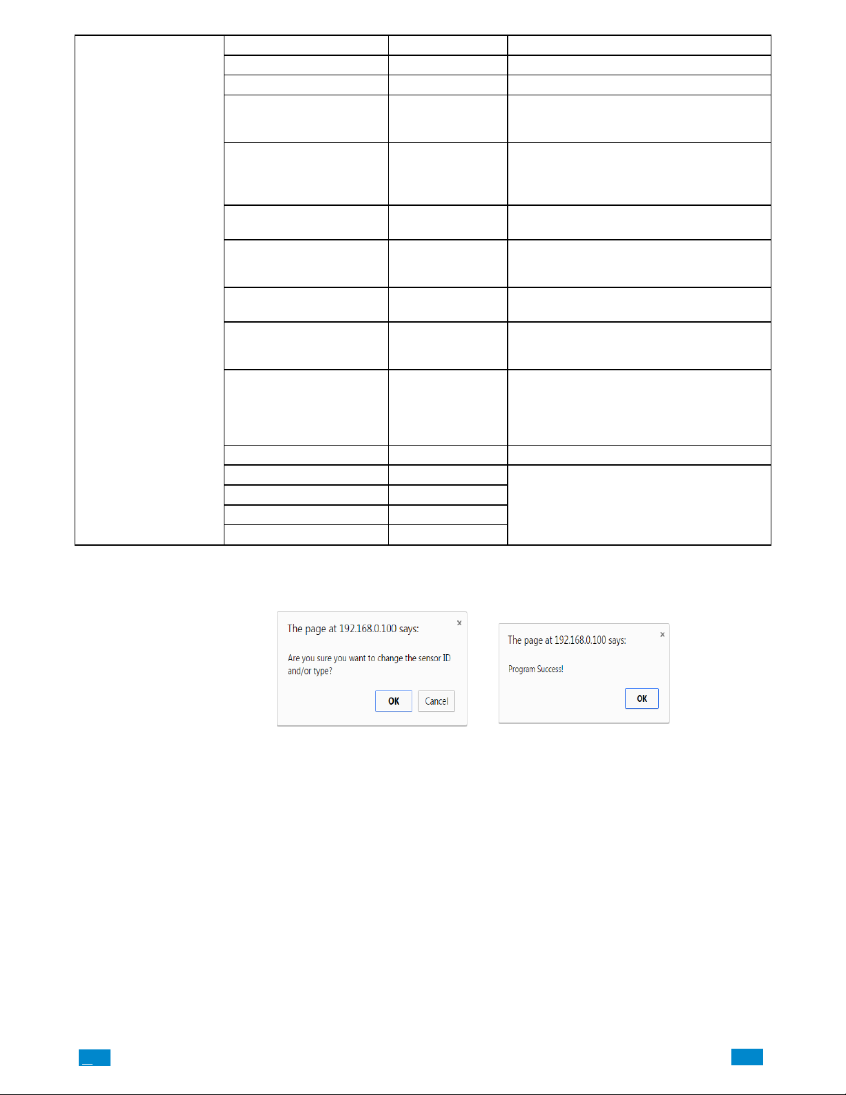
Sensor Configuration Men
u
Option Default Function
Select Sensor to Configure 1 Sensor Choose among 64 sensors.
Sensor Name Blank Custom 32 character name.
Sensor types determine the sensor attributes such
Sensor Type 3 Entry Exit Delay 1
Sensor Option 1 Bypass
Area Group 1 Area 1
Serial Number Blank
Tamper On
Disable Internal Reed Off
Norm Open External Contact Off
Signal Strength 0 Shows the last signal strength received.
Voice Name 1 Blank
Voice Name 2 Blank
Voice Name 3 Blank
Voice Name 4 Blank
as entry/exit, instant, etc. Additionally sensor types
determine the siren attributes.
Sensor options determine the sensor attributes such
as a sensor’s ability to be bypassed, force arm,
Cross Zone, stay mode, etc. Additionally sensor
options determine the sensors reporting attributes.
Assigning a sensor to an area will enable it to report.
This is the TXID of the wireless sensor, it can be
manual entered or the sensor can be ”Learned” into
panel.
Tamper switch on the wireless sensor is enabled or
disabled.
The internal reed switch(es) on the wireless device
can be disabled. Applies if the sensor is a device
type 10.
The external input on wireless sensors can be enabled. Check this box when external contact is normally open. If the 60−362N−10−319.5 sensor is
used the jumper pin does not have to be used. Applies if the sensor is a device type 10.
This feature uses the internal voice vocabulary to
name the sensor. These names will be announced
in sequence when the sensor is opened while in the
Chime mode.
When you are finished programming the Sensor
Press the Save button.
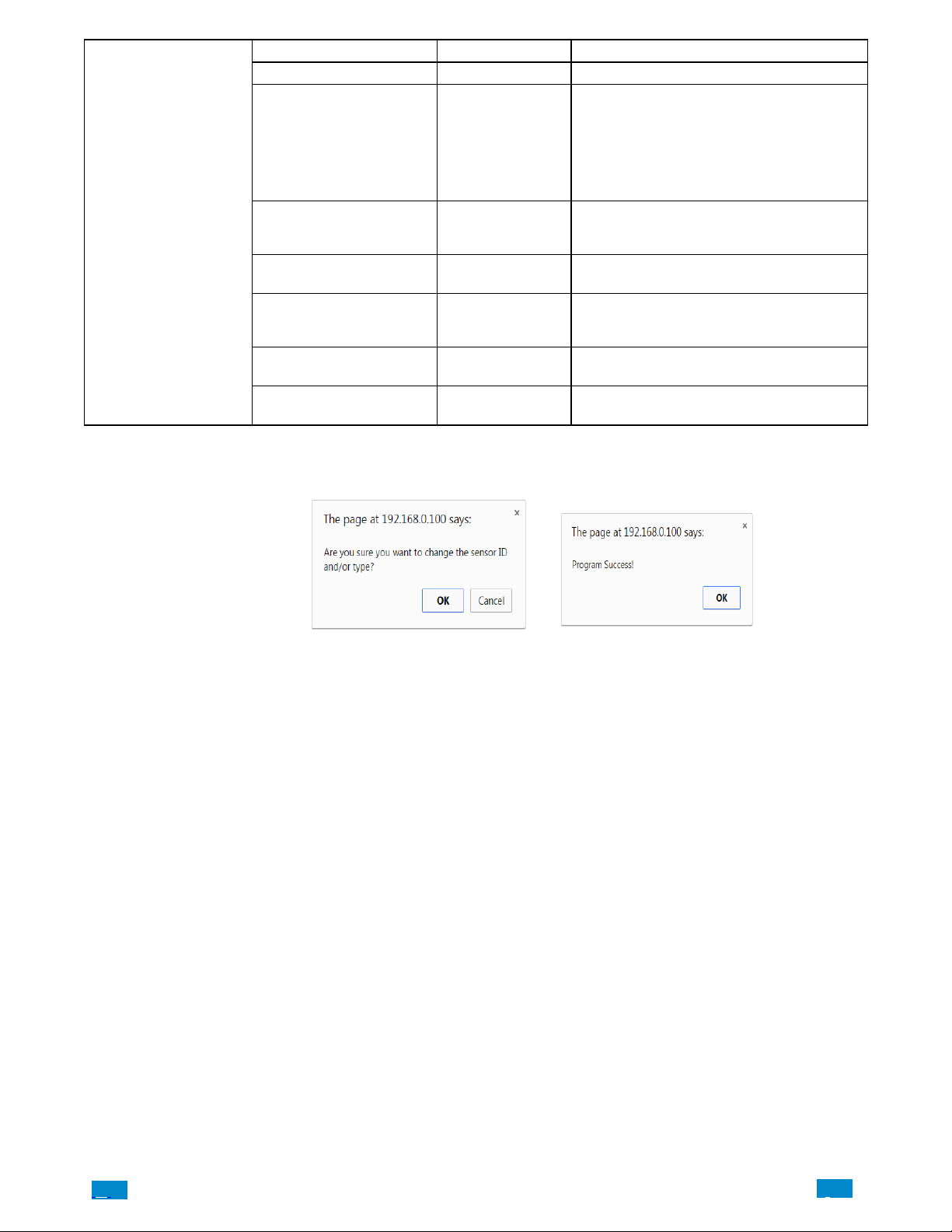
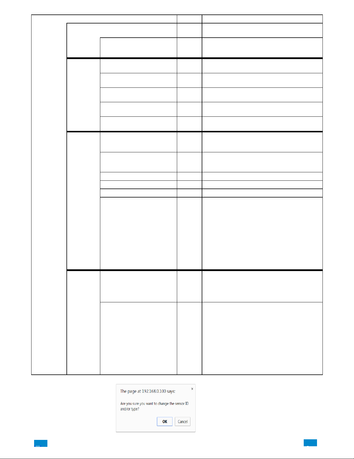
A dialogue box appears.
Press the OK button.
A dialogue box appears.
Press the OK button.
These dialogue boxes appear after any changes to the system are attempted/registered.
IMPORTANT: After you have finished programming a sensor, be sure to advance the sensor number in the drop down menu when
programming the next sensor. Otherwise you will over−write the sensor configuration you just programmed.
.C
33
..
.I
Page 34
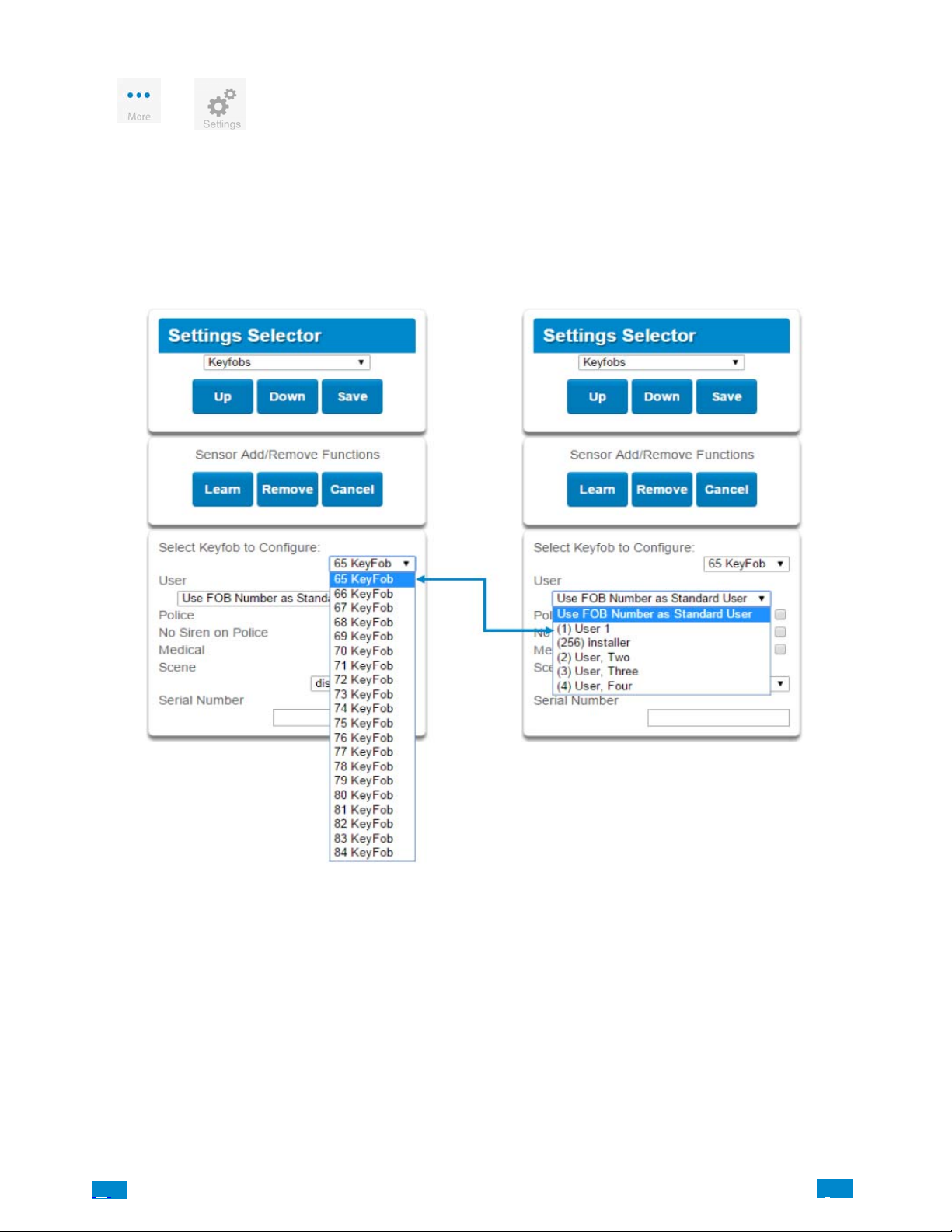
4.2 Learn in a Keyfob
Press then for the Settings Selector page.
Select the drop down menu under Sensors to see the list of programmable items.
Select Keyfobs.
With the keyfobs screen selected you can choose the keyfob number to configure and select the user number to link to the keyfob.
.C.
34
..
.I
Page 35
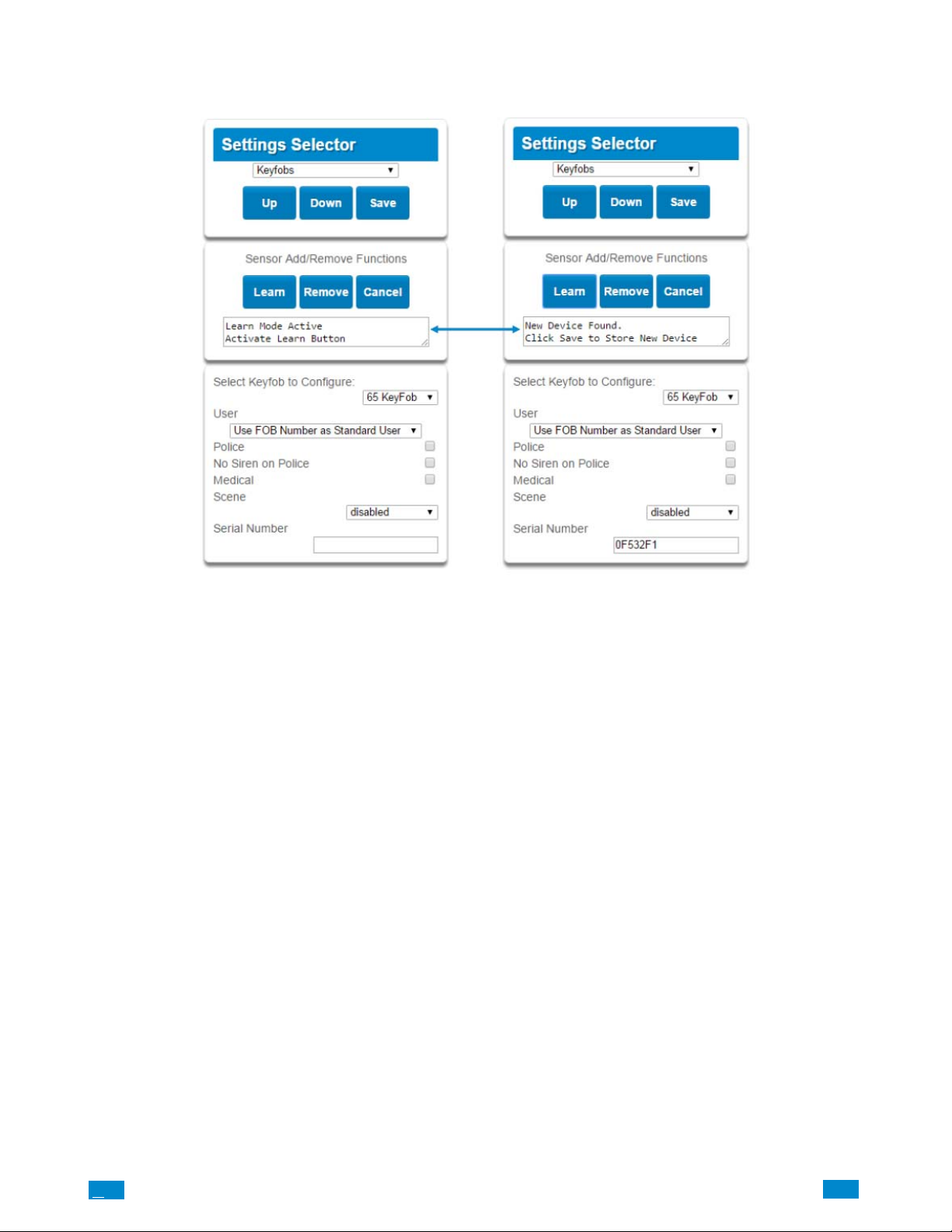
Give the keyfob a number (you are giving the keyfob a sensor number). Select the user and press Learn. A notification box will appear below
the Learn button. Activate the keyfob. Consult the keyfob manual for instructions; generally this is performed by simultaneously pressing the
Lock and Unlock buttons. This will send a tamper signal to Côr panel.
The notification box will alert you that a new device (keyfob) was found. The keyfob Serial Number box will be populated. Explanations of
the Keyfob configurations appear on the next page.
.C
35
..
.I
Page 36
Option Default Function
Select Keyfob to Configure 65 Keyfob This is the starting Sensor number for Keyfobs.
User
Keyfob Configuration
Menu
When you are finished programming the Keyfob,
Police Off
No Siren on Police Off
Medical Off
Scene Off
Serial Number Blank
Use FOB Number as
Standard User
If ”Use FOB Number as Standard User” is used,
when there is an activation on that Fob the Central
Station report will come in with that sensor number. If there is a user assigned to the fob that user
number will come in on the Central Station Report.
If no user is assigned it will show as user 999 in the
Central Station Report.
Enabling this will enable the Police / Panic on the
Fob, this will also be audible at the panel (top 2
buttons press at the same time).
With this enabled it will make the Police / Panic
silent at the panel.
Enabling this will enable the Medical / Aux on the
Fob. This will be an audible alarm at the panel.
(bottom 2 buttons pressed at the same time)
By using the drop down menu one of 16 scenes
can be activated.
This is the TXID of the Fob, it can be manually
entered or the sensor can be ”Learned” into panel.
Press the Save button.
A dialogue box appears.
Press the OK button.
A dialogue box appears.
Press the OK button.
These dialogue boxes appear after any changes to the system are attempted/registered.
.C.
36
..
.I
Page 37
4.3 Programming Areas
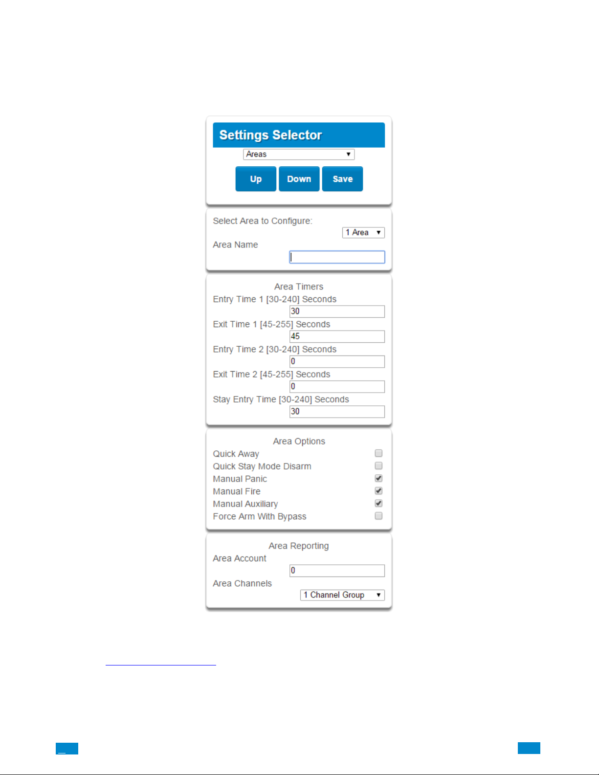
Select Areas from the drop down menu.
With the Areas screen selected you can choose an Area number to configure, give the area a name, and define attributes for that area. The
Côr can support a total of 4 areas; each area is configured with its entry and exit times, area options, area timers, area type and reporting
characteristics
Explanations of the Area configurations appear on the following pages.
Also reference Advanced Programming, Areas
, Section 5.3.
.C
37
..
.I
Page 38
Areas
n
s
Configuratio
Menu
Option Default Function
Select Area to Configure Area 1
Area Name Blank
Entry Time 1 (30−240) Seconds 30
Exit Timer 1 (45 − 255) Seconds 45
Area Timers
Area Option
Area
Reporting
Entry Timer 2 (30 − 240) Seconds 0
Exit Timer 2 (45 −255) Seconds 0
Stay Enter Timer (30 − 240)
Seconds
Quick Away Off
Quick Stay Mode Disarm Off
Manual Panic On Enables or Disables the Keypad Panic
Manual Fire On Enables or Disables the Keypad Fire
Manual Auxiliary On Enables or Disables the Keypad Auxiliary
Force Arm With Bypass Off
Area Account 0
Area Channels
30
1
Channel
Group
Use the drop down menu to select which of the 4 areas
to program.
Each area can be configured with a custom 32 character
name. The area name is displayed wherever an area is
referenced on the Côr system.
Provides time to enter into the premises to deactivate the
alarm system.
Provides time to exit the premise without activating the
alarm system.
If there is a second entry door that requires more time to
deactivate the alarm system.
If there is a second exit door that requires more time to
leave.
When the system is armed to ”ST AY” this will be the
entry time to deactivate the alarm system.
If enabled, the area can be armed in away mode with a
single press. When area is armed via quick away mode,
the closing user number is the default user of 999.
If enabled, this will allow the stay mode to be disarmed
by pressing the stay key on the Côr panel. If the system is in alarm a PIN must be used.
If enabled, the area can be armed even if sensors are not
ready. Any sensors that are not ready will NOT be automatically be bypassed and may cause an alarm condition because they could still be in a not ready state once
the area becomes armed.
This option is overridden if the Force Arm With Auto−
Bypass is enabled.
Individual sensors can be made “force arm−able without
auto−bypass” by leaving this area option off, then enabling Forced Arm Enable in Sensor options, and disabling Sensor Inhibit (Bypass) in the Sensor Type Profile.
This account number is ONLY used when sending an
email with a professionally monitored security alarm
company. This should be the same as the Central Station
account number, however if it is not this will not affect
the Central Station reporting.
If enabled, the area can be armed even if sensors are not
ready. Any sensors that are not ready will NOT be automatically be bypassed and may cause an alarm condition because they could still be in a not ready state once
the area becomes armed.
This option is overridden if the Force Arm With Auto−
Bypass is enabled.
Individual sensors can be made “force arm−able without
auto−bypass” by leaving this area option off, then enabling Forced Arm Enable in Sensor options, and disabling Sensor Inhibit (Bypass) in the Sensor Type Profile.
When you are finished programming the Area settings, remember
to save your changes.
.C.
38
..
.I
Page 39
4.4 Programming the System
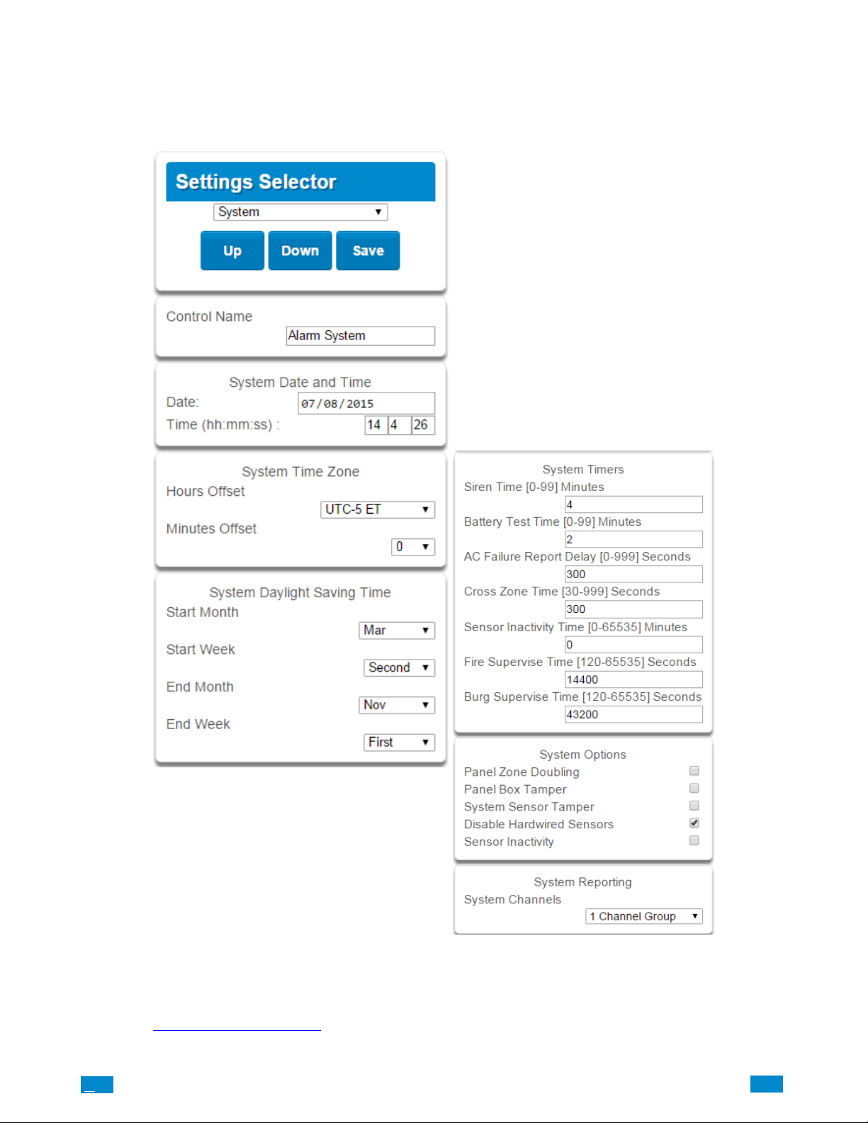
Select System from the drop down menu.
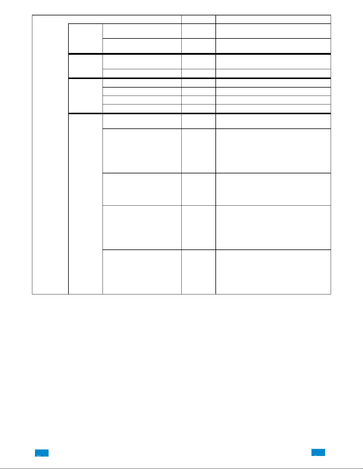
When the System screen is selected you can program several system wide settings, including the system clock and timers, as well as sensor
options and reporting.
When you are finished programming the System settings, remember to save your changes.
Explanations of the System configurations appear on the following pages.
Also reference Advanced Programming, System, Section 5.1.
.C
39
..
.I
Page 40
System
Configuration
Menu
Date & Time
Time Zone
Daylight
Saving Time
System
Timers
Option Default Function
Date
Time (hh:mm:ss)
Hours Offset UTC 5ET
Minutes Offset 0 This is used in other locations throughout the world.
Start Month Mar Standard
Start W eek Second Standard
End Month Nov Standard
Start Month First Standard
Siren Time (0−99) Minutes 4
Battery T est Time (0− 99) Minutes 2
AC Failure Report
Delay (0−999)
Seconds
Cross Zone Time (30− 999) 300
Sensor Inactivity Time
(0−65535) Minutes
300
0
Once it is connected to Côr the Date and time are
automatically synced.
Once it is connected to Côr the Date and time are
automatically synced.
Starting with EST is UTC−5, CST is UTC−6, MT is
UTC−6, PST is UTC−7.
The siren time sets the time in minutes that the siren
output is active.
The battery test time sets the duration in minutes
that the Côr will perform a dynamic battery test.
The Côr will perform a dynamic battery test at the
disarming of the first area or at midnight once each
24−hour cycle. Dynamic battery test is disabled
when the test duration is set to 0. Dynamic battery
test can also be run manually from a keypad.
The AC fail report delay sets the duration in seconds
that the AC power is lost or restored before a communication is initiated.
AC restore will report when power is maintained for
this same duration.
The Cross Zone time sets the duration in seconds
whereby two or more sensors must trip before an
alarm condition will be registered or the one sensor
must trigger twice within this time period, or a continuous trip longer than 10 seconds. This feature
only applies to sensors with the Cross Zone feature
set in sensor options.
Sensors programmed with Sensor Inactivity in the
Sensor Options must be opened and closed within
the time programmed here (in minutes). If they do
not, a Sensor Inactivity will report. This feature can
be enabled in the System Options menu.
Default Sensor Inactivity option is off and this timer
is set to 10080 minutes (7 days).
.C.
40
..
.I
Page 41

System
Configuration
Menu
System
Timers
System
Options
System
Reporting
Option Default Function
This applies only to wireless sensors programmed as
fire type. Sensors send a reduced packet count supervisory signal every 60 minutes (check your sen-
Fire Supervise Time (120−65535)
Seconds
Burg Supervise Time (120−65535) 14400
Panel Sensor Doubling Off
Panel Box Tamper Off
System Sensor Tamper Off
Disable Hardwire Sensors On
Sensor Inactivity Off
System Channel
14400
1 Channel
Group
sor manual for most up to date details). If no supervisory signal is received by the panel within the
time specified here then the sensor will be reported
as missing. When set to 0 the default of 14,400 seconds (4 hours) will be used. Check your local regulations for the correct value to use.
This applies only to wireless sensors programmed as
non−fire type. Sensors send a reduced packet count
supervisory signal every 60 minutes (check your
sensor manual for most up to date details). If no
supervisory signal is received by the panel within
the time specified here then the sensor will be reported as missing. When set to 0 the default of
43,200 seconds (12 hours) will be used. Check your
local regulations for the correct value to use.
If enabled, the two (2) hardwired sensor inputs will
be doubled to support four (4) sensors. The terminals for Sensor 1 will represent sensors 1 and 3, and
the terminals for sensor 2 will represent sensor 2 and
4. This option cannot be selected for sensors other
than the two sensors on the main panel. This option
cannot be used in conjunction with the DEOL option.
The Côr panel has a built−in normally closed tamper switch that will sound the siren if the panel is
removed from the wall. This option will enable or
disable this tamper switch.
If enabled, the Côr panel will monitor all sensors,
except fire sensors, for Dual End of Line (DEOL).
A short or open circuit on a DEOL will activate sensor tamper alarms. This feature cannot be used if
Panel Sensor Doubling is enabled.
If enabled, the Côr panel will disable all hardwired sensor inputs.
If enabled, the Côr system will monitor each sensor for activations. If no activations occur within the
sensor activity time then a failed sensor activity report may be reported via the selected communication channel and a failed sensor activity message set
in the Côr event log. For a sensor to be eligible
for activity monitoring, it must have “Sensor Activity” set in sensor options.
Sensors programmed with Sensor Inactivity in the
Sensor Options must be open and closed within the
time programmed here (in minutes). If they do not,
a Sensor Inactivity will report.
The Channel Group that the Côr will send system
events to.
.C
41
..
.I
Page 42
4.5 Programming Channels
Select Channels from the drop down menu.
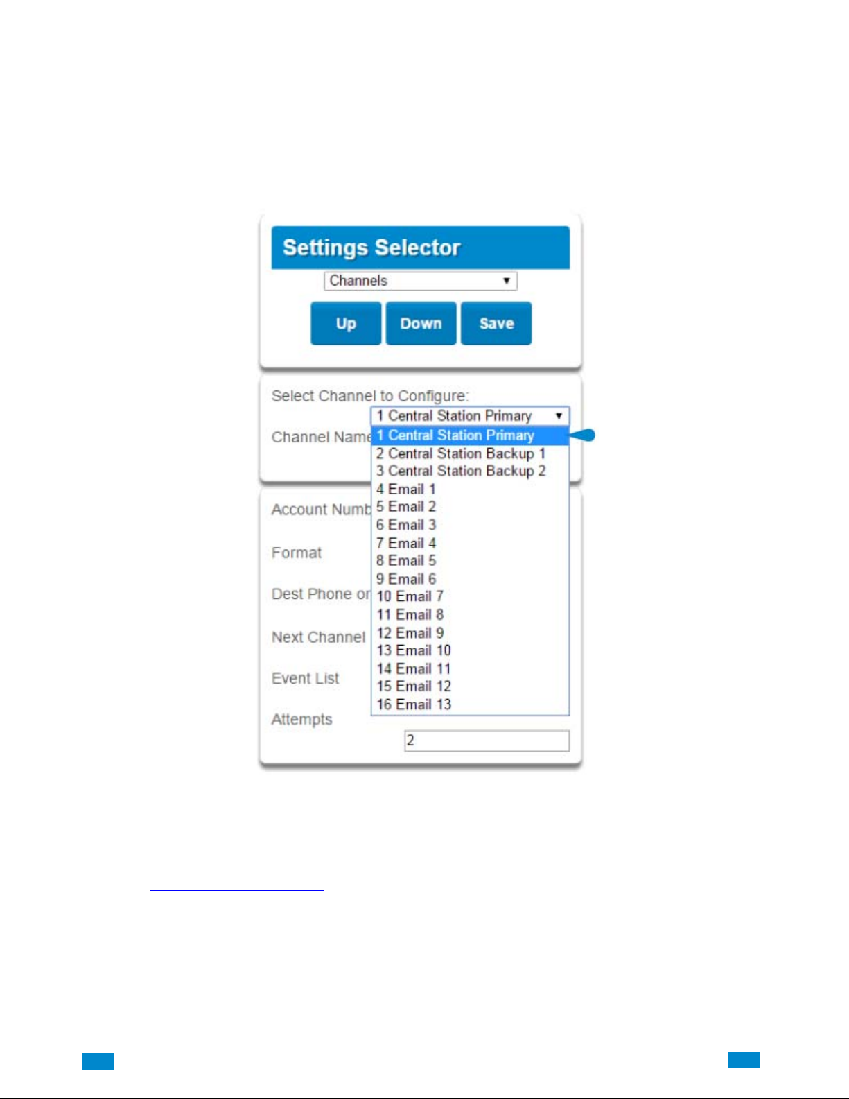
With the Channels screen selected you can program a communication path for events to be sent from the Côr panel to a selected destination.
The Côr panel can support a total of 16 channels; each channel is identified by a unique channel number, which cannot be altered, and
remains as the key reference for each channel.
Choose a channel in the drop down menu and assign it attributes.
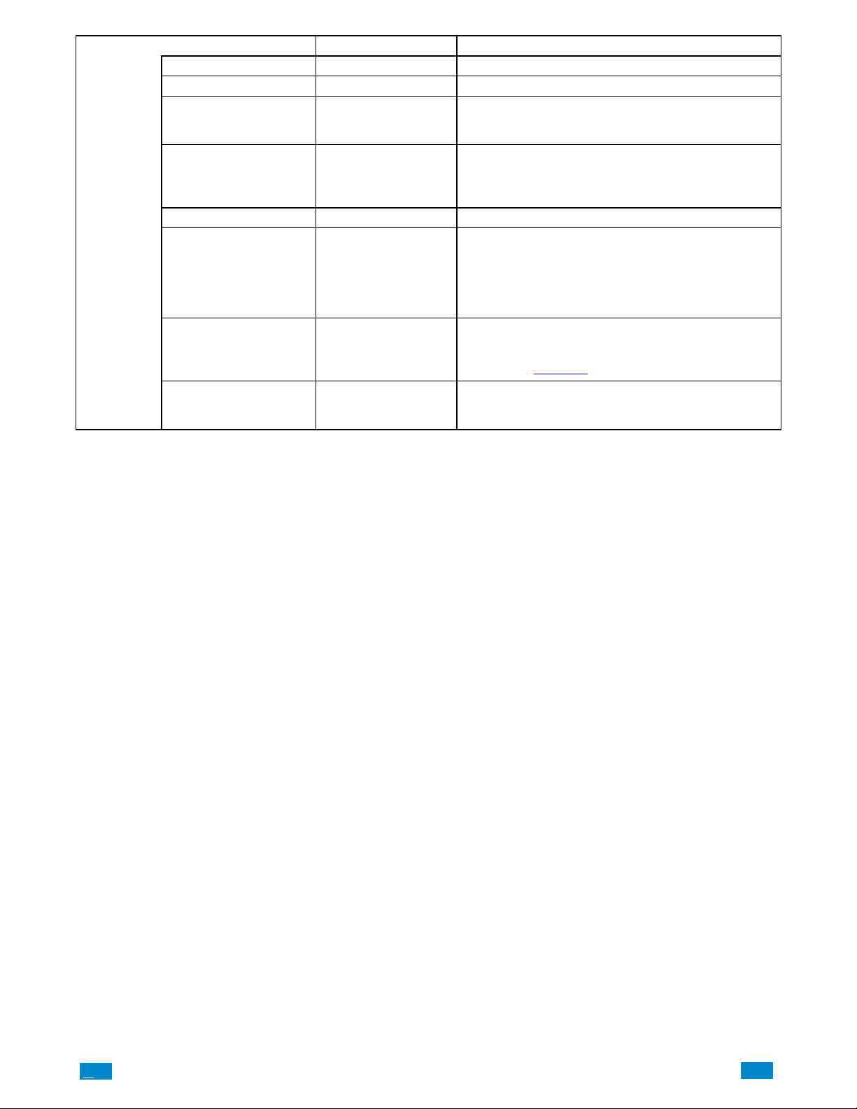
Explanations of the Channel Configuration menu appear on the following page. If homeowner wants to get email notifications, select email
from the options and enter their email address.
Also reference Advanced Programming, Channels
When you are finished programming the Channel settings, remember to save your changes.
.C.
, Section 5.4.
42
..
.I
Page 43
Channel
Configuration
Menu
Option Default Function
Select Channel to Configure 1 Central Station Primary
Channel Name Central Station Primary Custom names of the selected channel can be created here.
This is the Account Number that will be reported with the
Account Number Blank
Format UltraSync
Desk Phone or Email Blank The phone number or email address of the selected destination.
Central Station Backup 1
Central Station Backup 2
Next Channel
Event List 1 Event List
Attempts 2
Email 1
Email 2
Email 3
Etc.
event in email reports. When UltraSync format is selected, this
field will not be used.
This is the communication format for the selected channel.
Select from:
UltraSync
Email
If the channel selected is unable to deliver the event to the
selected destination, Côr will use this backup channel if the
primary channel fails. The Next Channel specified here must
be greater than the Channel Number.
Select the pre−programmed list of events that will be sent via
this channel. The specific event in each event list is programmed in Advanced Programming, Channels. See Channels
Programming Event List.
Enter the number of times Côr should try to send the events
to the UltraSync server. After the number of attempts has been
exhausted the Côr will try the Next Channel if specified.
.C
43
..
.I
Page 44
4.6 Programming the Network
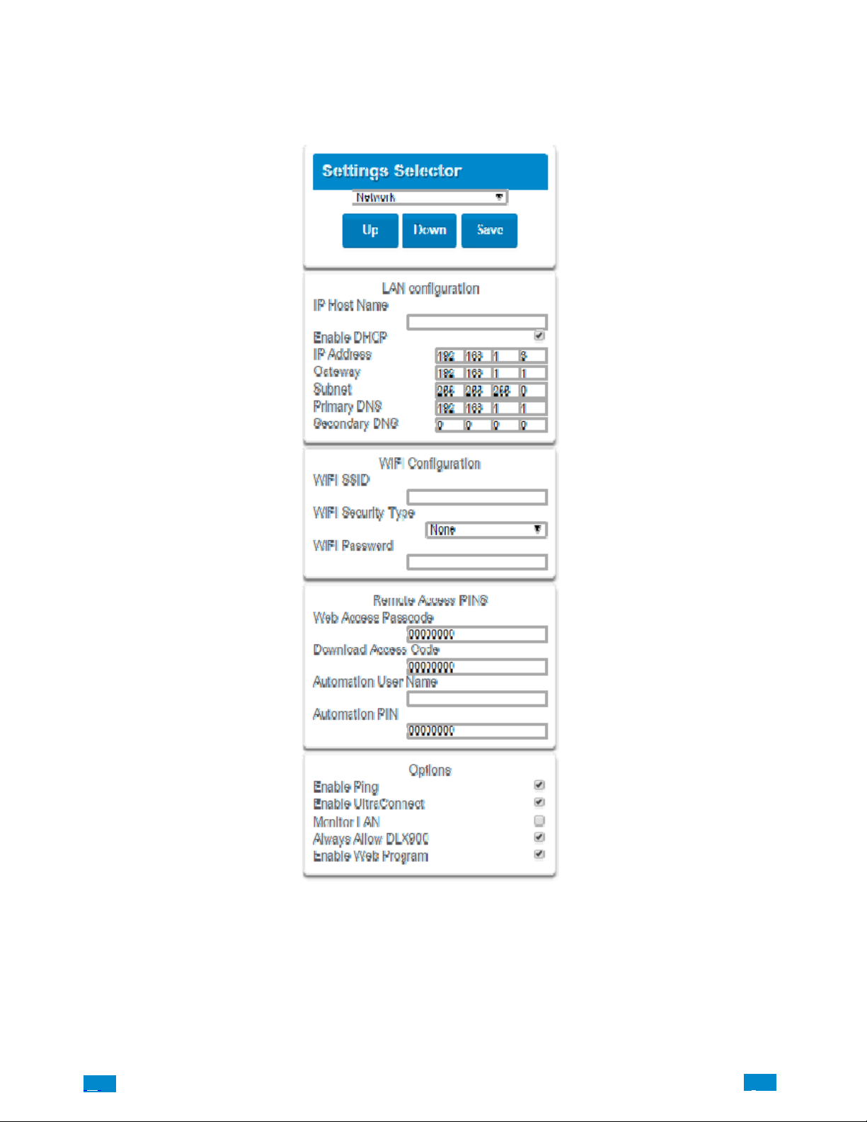
Select Network from the drop down menu.
Enter your network settings on this page.
Explanations of the Network configuration menu appear on the following pages. Remember to save your changes when you are finished
programming the Network setting.
.C.
44
..
.I
Page 45
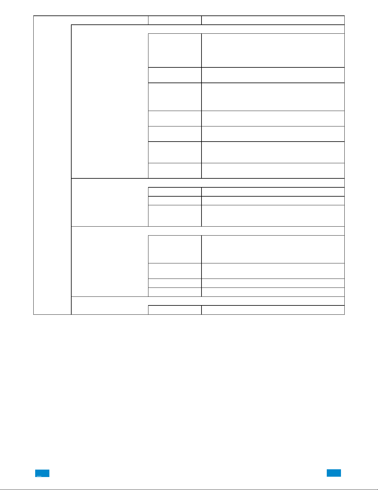
Network
Configuration
Menu
Option Default Function
LAN Configuration
IP Host Name −
Enable DHCP Off
Primary DNS −
Secondary DNS −
Wi Fi Configuration
Wi Fi Security type Blank WEP/WEP−128bit/WPA2−Passphrase
Wi Fi Password Blank
Remote Access PINS
WEB Access Passcode 0
Download Access Code 0
Automation User Name Blank Used when there is API integration.
Automation PIN Blank Used when there is API integration.
Options
A text label assigned to the Côr communicator so you do not
have to remember the IP Address.
Note: This only works on local LAN and with Microsoft Windows PC, or an Apple device with the .local extension. Does
not work remotely over the internet.
Allows the Côr panel to be automatically assigned an IP
address by the network.
The IP address assigned to the Côr which enables it to con-
IP Address −
Gateway −
Subnet −
Wi Fi SSID Blank Wi Fi Network name the Côr panel is connecting to.
Enable Ping On Allows the Côr panel to respond to the PING command.
nect to the local LAN. This will allow you to access the embedded web server from the Côr panel to program and view
the status of the system. It is also used for alarm reporting.
If required, the IP address of the router which is needed when
remote IP communications are used.
The subnet mask for the network. For example, 255.255.255.0
is the network mask for 192.168.1.0/24
The IP address of the Primary Domain Name Server. The DNS
is used to translate host names for time servers and UltraSync
servers.
The IP address of the Secondary Domain Name Server, used if
the Primary DNS is not available.
Network password, which must match the password assigned
to the WIFI SSID (access point). There can be no special charterers, only Alphanumeric
The Côr app requires the W eb Access Code to get access to
the panel. The default Web Access Passcode of 00000000
disables remote access. The system allows for an 8 digit numeric (only) code. Each owner should have a unique number.
Enables remote access for DLX900. The default Download
Access Passcode of 00000000 prevents remote access.
.C
45
..
.I
Page 46
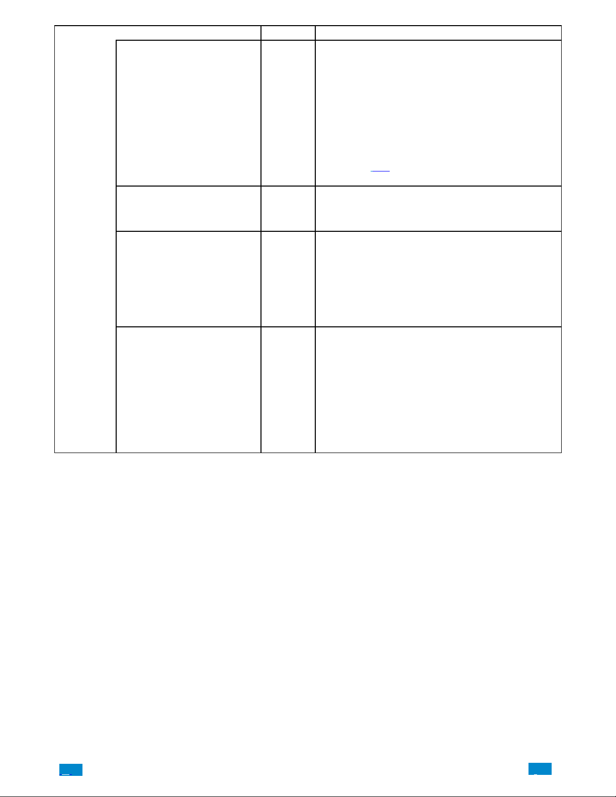
Network
Configuration
Menu
Option Default Function
Enable Ultraconnect (UltraSync) On
Monitor LAN Off
Always Allow DLX900 On
Enable Web Programming On
This is an automatic feature of Côr. It is recommended you
leave this setting on.
Enable this option to allow Côr to send email reports via the
UltraSync servers. This is independent of the W eb Access Passcode which when set to 00000000 will prevent the Côr app
from connecting.
If any channel is set to Email format reporting, then Côr will
override ignore this setting and allow email reporting via UltraSync cloud servers.
If you wish to prevent connections of Côr to the UltraSynccloud
servers, then uncheck this option and do not use the UltraSync
reporting format.
Also reference
Communicator.
When the Monitor LAN option is enabled the panel will monitor
the Ethernet port for a valid Ethernet cable. If the Ethernet cable is
disconnected while this option is enabled and the panel is unable
to communicate, it will log a Fail T o Communicate event.
Enabling this option will allow DLX900 to connect at any time if
the correct Download Access Code is provided.
Disabling this option provides greater security by only allowing
DLX900 to connect when program mode is active. This allows the
system to have DLX900 access disabled until a user on site with
physical access to the keypad enters program mode with a valid
PIN code.
Côr will be in program mode if a user gains authorized access to
menu 5, 8, or 9 on the keypad.
Enabling this option will allow Côr Web Server and app to always display Installer menus regardless if the panel is in program
mode or not.
Disabling this option will hide the Installer menus on Côr Web
Server and app unless program mode is active. This provides
greater security by keeping web programming disabled unless a
user on site with physical access to the keypad enters program
mode with a valid PIN code.
Côr will be in program mode if a user gains access to menu 5,
8, or 9.
Côr app requires a Web Access Code other than 00000000 to
get access to the panel.
table in submenu 16 of Advanced Programming,
.C.
46
..
.I
Page 47
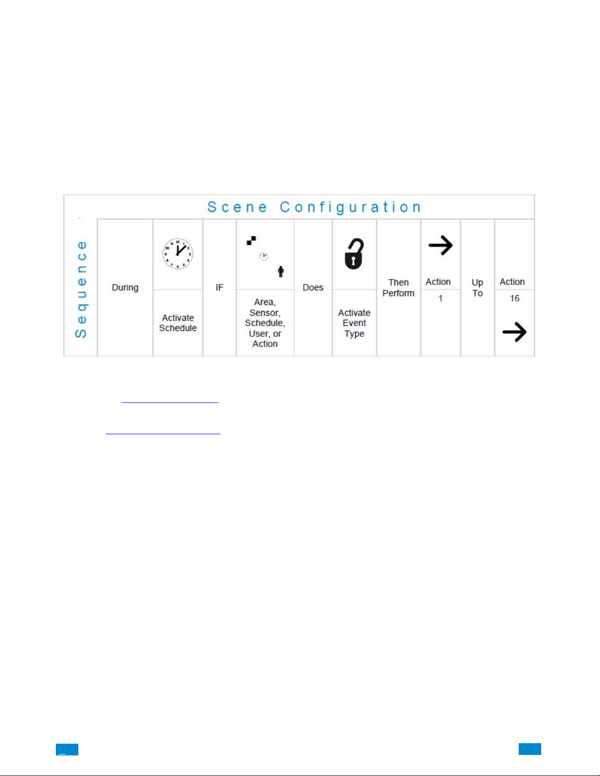
4.7 Programming Scenes
Select Scenes from the drop down menu.
With the Scenes screen selected you can create scenes on schedules and determine which event types and device triggers will activate them.
Each scene can trigger up to 16 consecutive scene actions when certain conditions are met. This can save users time by automatically running
multiple actions. A scene can be triggered manually, through a schedule, or via a system event.
Remember to save your changes when you are finished programming the Scene settings.
Explanations of the Scene Configuration Menu appear on the following pages.
Also reference Advanced Programming, Scenes
, Section 5.18.
.C
47
..
.I
Page 48
Settings Selector
Automations (Scenes)
Save
Select Scene to Congure:
3 Scene
Scene Name
Scene Trigger
When Should Scene Work
Always On
Scene Trigger Type
disabled
Activate Sensor
Device
disabled
Scene Result 1
Device
disabled
Scene Result 2
Device
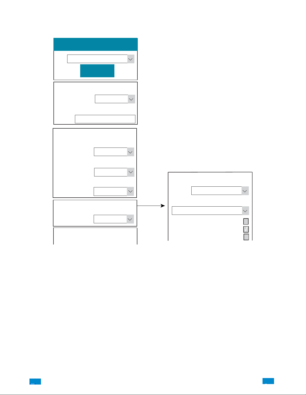
Example Scene
1. Enter a Scene Name.
2. Select the Scene to Configure drop down menu to restrict when the scene will be enabled
3. Select the event that will trigger recording a video clip using the Scene Trigger drop down menu.
4. Select the Activate Sensor/Area/User/Action if applicable.
5. Select Device (1) Alarm System. This enables another drop down menu for Action Type. Choose the Action Type “Trigger Camera
Video Clip”, then the camera you wish to record a video clip when the event is triggered.
Action Type
Trigger Camera Video Clip
1 Front door
2 Indoor
3 Camera
Scene Result 1
(1) Alarm System
A160068
6. Press Save.
.C.
48
..
.I
Page 49
Scene
r
r
Configuration
Menu
Option Default Function
Select scene to Configure
When should scene work Always On
Scene Trigge
Scene Trigger Type Disable
Activate Sensor Disabled
Scene Name
Scene Action 1
Action Device
Scene Action 1
Action Device
Scene Action 2
Action Device
Scene Action 3
Action Device
Scene Action 4
Action Device
Scene Action 5
Action Device
Scene Action 6
Action Device
Etc. Etc.
Etc. Etc.
Disabled
Disabled
Disabled
Disabled
Disabled
Disabled
Disabled
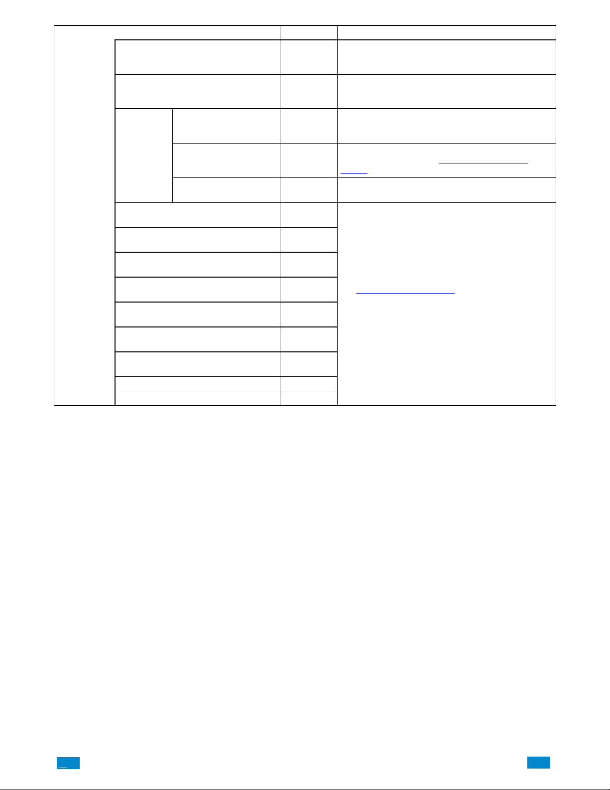
The Côr can support a total of 16 Scenes. Each Scene is
identified by a unique number, which cannot be altered,
and remains the key reference for each Scene.
Each Scene can be configured with a custom 32 character
name. The name is displayed wherever a Scene is referenced on the Côr system.
Select the Schedule that controls when this Scene is active.
If the current date and time is outside of the selected schedule, then the Scene will not run.
Select the event that will trigger this Scene. You can reference Activate Events list in Advanced Programming,
Scenes.
Select which Area \ Sensor \ Schedule \ User \ Action \
Device will provide the trigger for the Scene.
Each scene can perform up to 16 Scene Actions. These are
simplified actions that allow you to control devices on you
system. There are two types of Scene Action
1. Alarm System Action
2. Z−Wave Device Action.
Alarm System Action
Result T ype − The event of the Action Result to perform.
See Advanced Programming, Scenes and the Scene Action
and Scene Action Events T ypes
Result Number − Select the area / scene / camera
number to control:
Z−Wave Device Action
To display Z−Wave Action Types you must first learn in a
Z−Wave device. The Z−Wave device name will then appear.
Action Device – select the Z−W ave device you want to
control
Z−Wave Type 8 Setting 1 – depends on Z−Wave device.
May include options such as On, Off, Heat, Cool, Auto,
Up, Down, Lock, Unlock.
for reference.
.C
49
..
.I
Page 50
4.8 Programming Schedules
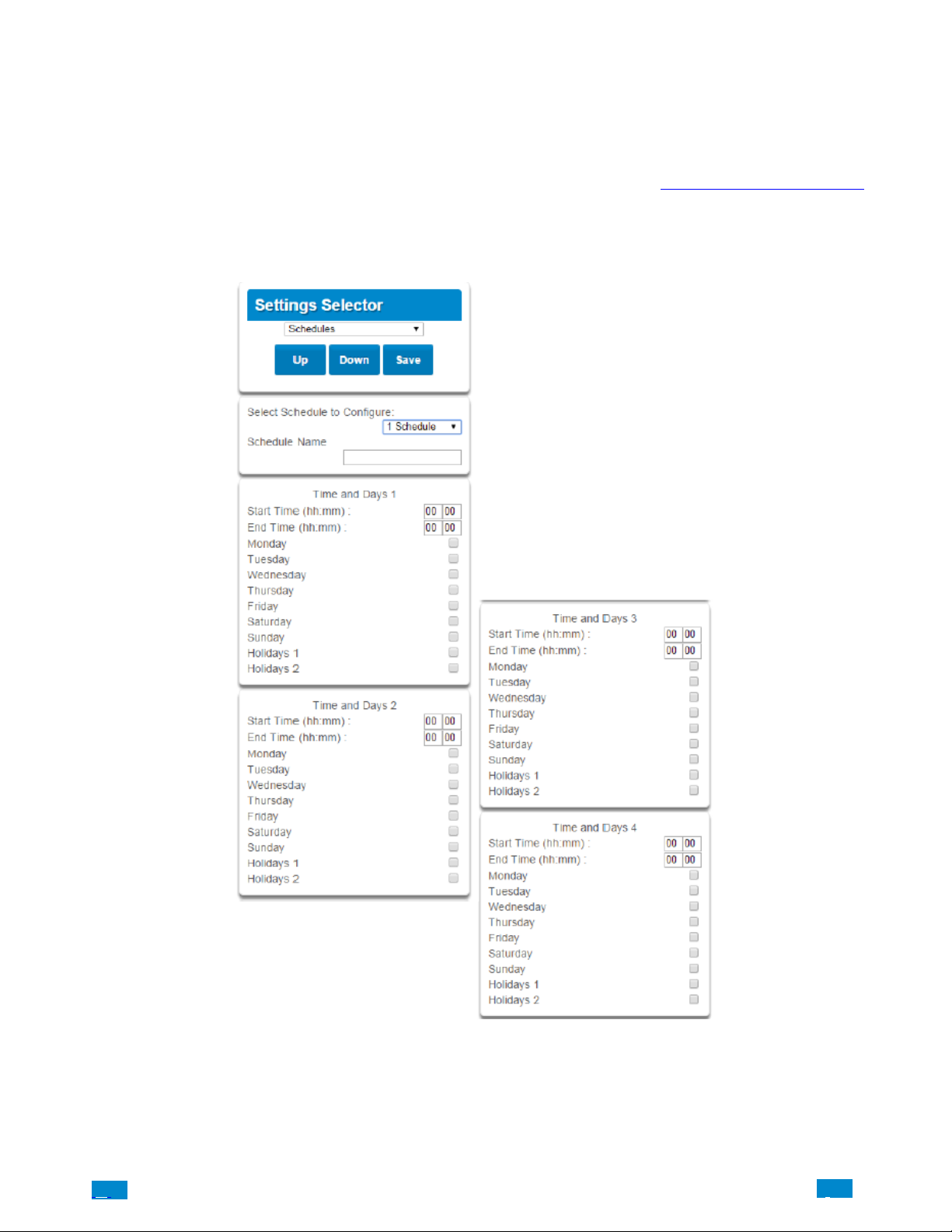
Select Schedules from the drop down menu.
With the Schedules screen selected you can create up to 16 schedules, each having four time and day periods.
Explanations of the Schedules Configuration menus appear on the following pages. Also reference Advanced Programming, Schedules,
Section 5.6.
Remember to save your changes when you are finished programming the Schedules settings.
.C.
50
..
.I
Page 51
Schedules
Configuration
Menu
Time and
Days 1−16
Option Default Function
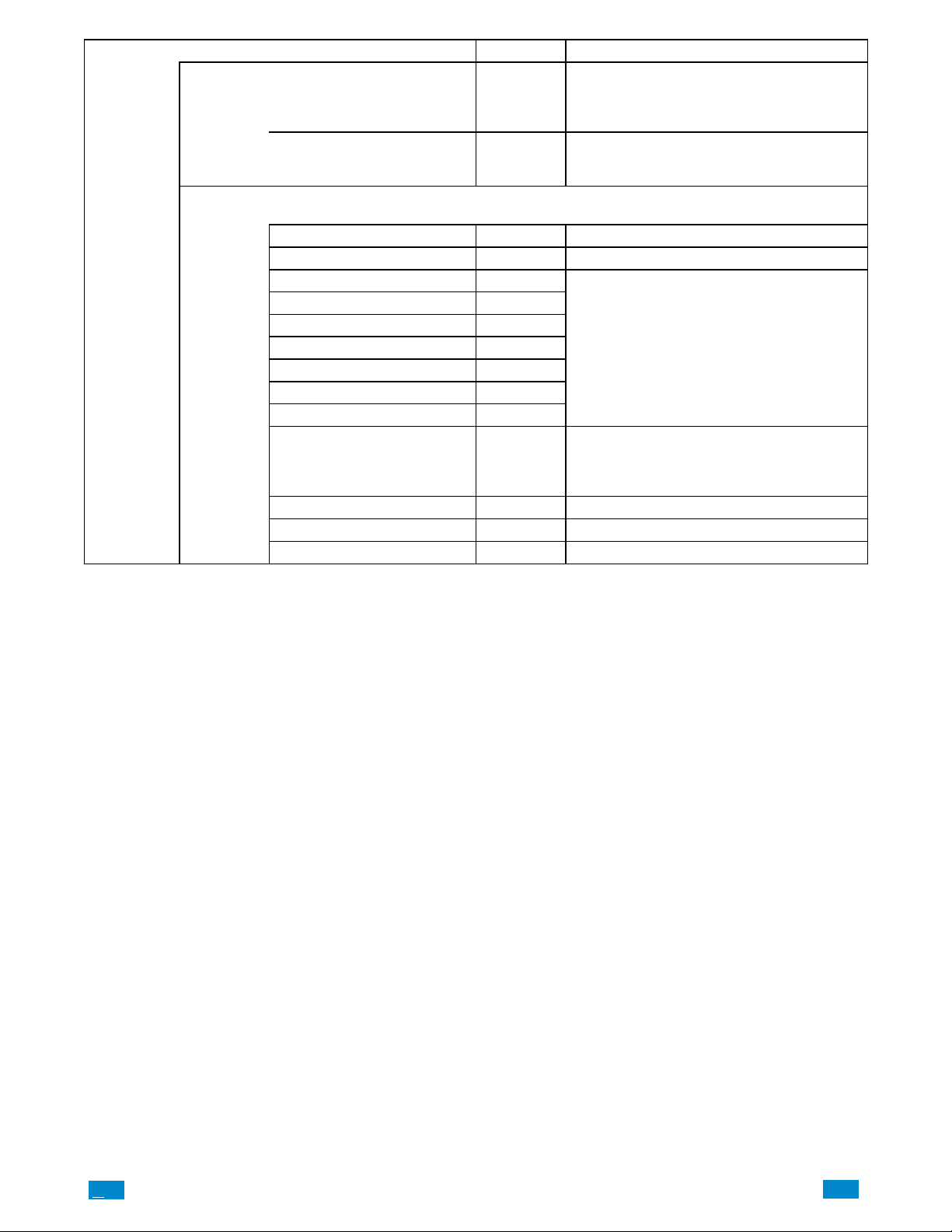
The Côr can support a total of 16 schedules. Each
Select Schedule to Configure 1 Schedule 1
Schedule Name Schedule 1
Up to 16 Start and Stop times can be created.
NOTE: Côr handles schedules that span midnight automatically.
Start Time (hh:mm) − Enter in the start time
End Time (hh:mm) − Enter in the stop time
Monday −
Tuesday −
Wednesday −
Thursday −
Friday −
Saturday −
Sunday −
Holiday 1 −
Holiday 2 − Same as Holiday 1
Holiday 3 − Same as Holiday 1
Holiday 4 − Same as Holiday 1
schedule is identified by a unique schedule number,
which cannot be altered, and remains as the key reference for each schedule.
Each schedule can be configured with a custom 32
character name. The area name is displayed wherever a schedule is referenced on the Côr system.
Enter in the days of the week the schedule is to be
active
Enter in the holiday that this schedule will be following.
NOTE:When the holiday is enabled the schedule
will not be active.
.C
51
..
.I
Page 52
4.9 Programming Holidays
#
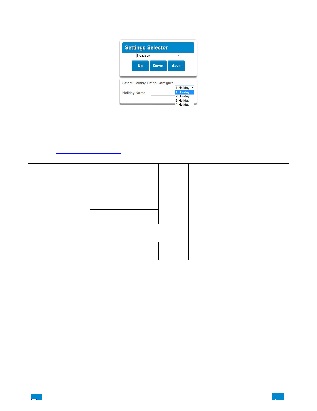
Select Holidays from the drop down menu.
With the Holidays screen selected you can create up to four sets of holiday dates for Côr. Set the number, name and date range for each
holiday. Holidays are then assigned to the schedules and used to deactivate the schedule while the holiday is active. Remember to save your
changes when you are finished programming the Holidays settings.
Explanations of the Holiday configurations appear below.
Also reference Advanced Programming, Holidays, Section 5.13.
Holiday
Configuration
Menu
Holiday
Start − End
Option Default Function
Côr supports up to 4 sets of holiday dates, each
Select Holiday
List to Configure
1 Holiday
2 Holiday
3 Holiday
4 Holiday
Holiday Name
Start Date n/a
End Date n/a
n/a
n/a
set can have up to 16 date ranges. Holidays are used
as part of Schedules to control access to the system
on specified dates.
The Côr panel can support a total of 4 Holiday
Sets. Each set is identified by a unique number,
which cannot be altered, and remains as the key reference for each area.
Each holiday can be configured with a custom 32
character name. The name is displayed wherever a
Holiday is referenced on the Côr system.
Select the date range for the Holiday by specifying
the start and stop date. A total of 16 ranges can be
entered for each Holiday.
.C.
52
..
.I
Page 53
Example Holiday List
Holiday 1 US Holiday List 2016
Date Range 1 − 01/01/2016 01/01/2016 New Year’s Day Friday, January 1
Date Range 2 − 30/05/2016 30/05/2016 Memorial Day Monday, May 30
Date Range 3 − 04/07/2016 04/07/2016 Independence Day Monday, July 4
Date Range 4 − 05/09/2016 05/09/2016 Labor Day Monday, September 5
Date Range 5 − 24/11/2016 24/11/2016 Thanksgiving Day Thursday, November 24
Date Range 6 − 26/12/2016 26/12/2016 Christmas Day (observed) Monday, December 26**
Date Range 7 −
Date Range 8 −
Date Range 9 −
Date Range 10 −
Date Range 11 −
Date Range 12 −
Date Range 13 −
Date Range 14 −
Date Range 15 −
Date Range 16 −
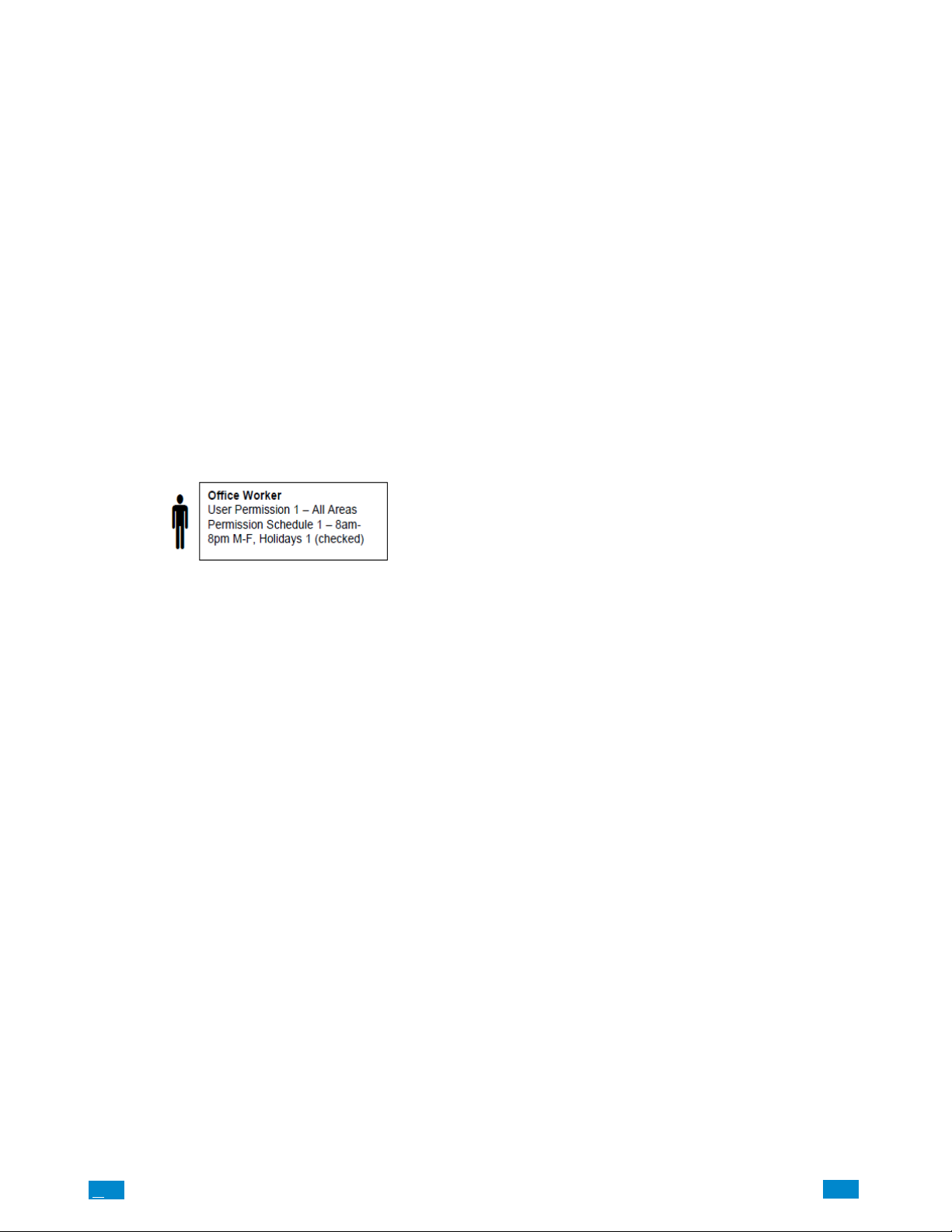
An office is not staffed during a public holiday and you want to prevent access to the building from staff on this date. First program the
holiday dates in this section under “Holiday 1”, then go to Schedules and check “Holidays 1”, then assign that schedule to the User.
.C
53
..
.I
Page 54
4.10 Programming Z−Wave Devices
See the Z−Wave Configuration Menu later in this section.
Also reference Advanced Programming, Devices
, section 5.9.
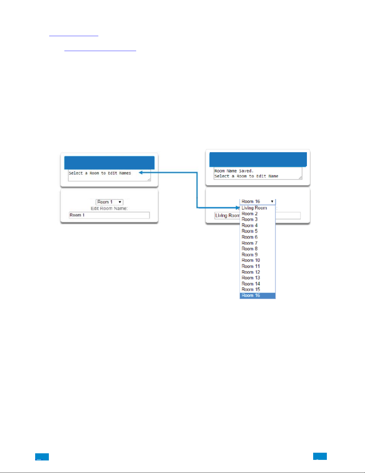
Z−Wave Room Names
Select Z−Wave Room Names from the drop down menu.
From the drop down menu under Z−Wave Room Editor select a room to edit the name.
For this example we will change the name of Room 1 to Living Room.
Type Living room in the form “Edit Room Name”. This can be a 32 character name.
Press Save. The notification box will alert you that the Room Name is Saved. The drop down list has been updated for Room 1.
Z-Wave Room Editor
Z-Wave Room Editor
Z-Wave Room Editor
Z-Wave Room Editor
A160050
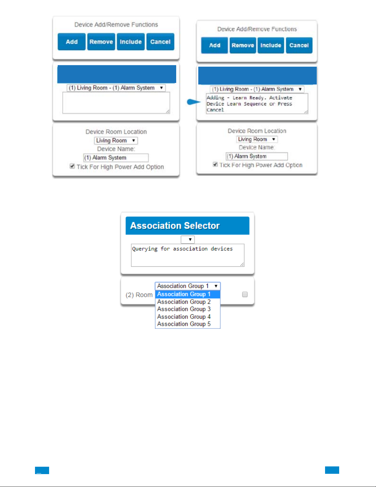
Add a Z−Wave Device
Select Z − Wave Add/Remove from the drop down menu.
1. Press Add
2. Initiate ADD mode on Z−Wave device. See your Z−Wave device’s manual for instructions. The notification box will alert you that the
Device is added.
NOTE: If a Z−Wave device has been added before or to another system, you must first remove it before adding it to this system. To
do this, press Remove, then activate LINK or REMOVE mode on the device.
3. Press Rooms.
4. Check that you can see the device you just added. Press a button such as ON or OFF to verify that you can control the device.
.C.
54
..
.I
Page 55
Z-Wave Device Selector
Z−Wave Device Association
Select Z−Wave Device Association from the drop down menu.
Z-Wave Device Selector
A160051
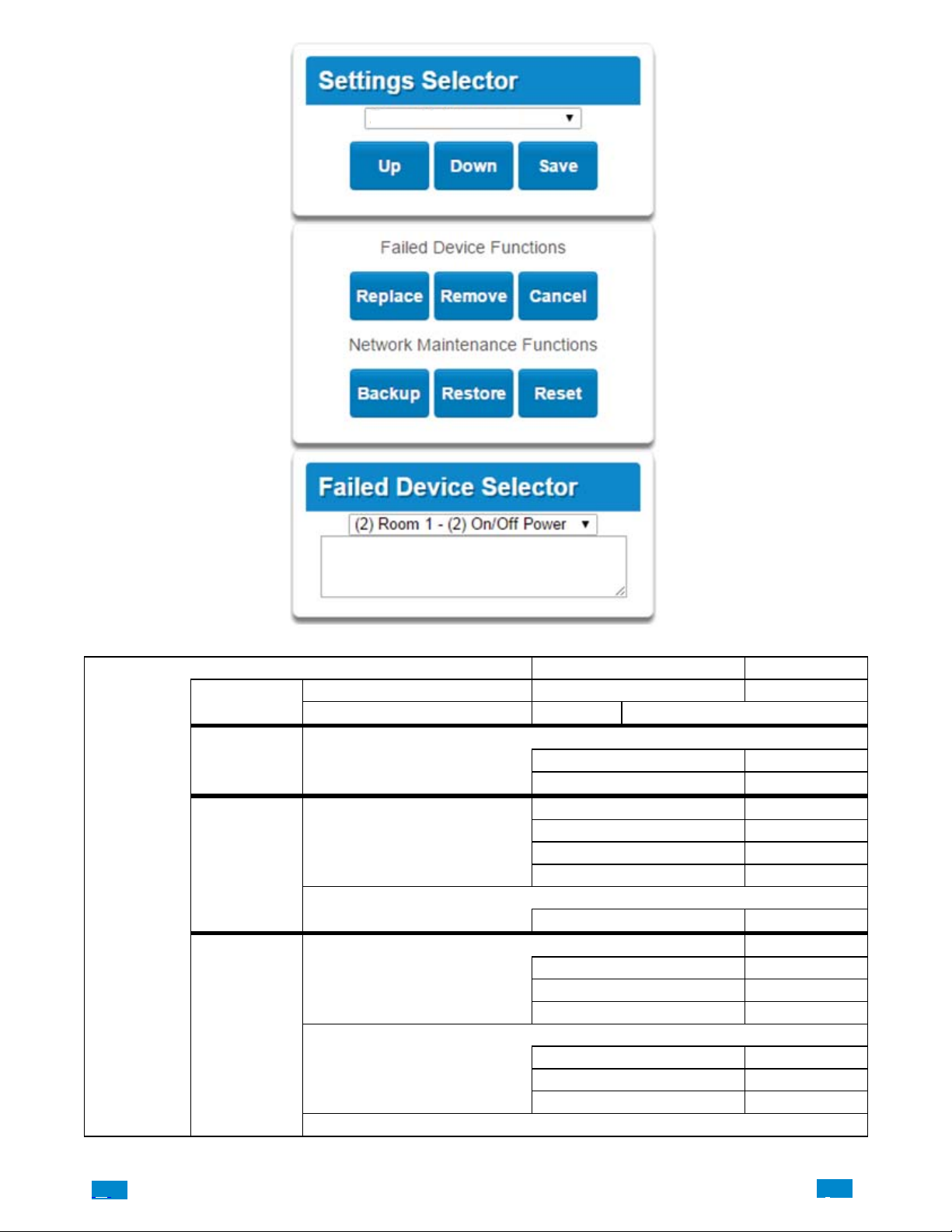
Z−Wave Maintenance
Select Z −Wave Maintenance from the drop down menu.
The Z−Wave Maintenance page main tile contains additional buttons from the settings tile.
Failed Device Functions:
REPLACE: This option is used when a Z−Wave device is defective, and it allows the replacement of the device while keeping the same
Device number. The device number is what is used in Scenes association.
REMOVE: This option is used when a Z−Wave device is missing or is damaged to the point that it will not transmit signals.
BACKUP: This saves the Z−Wave programming to the Côr panel.
RESTORE: This restores the Z−Wave programming to the last time is was saved.
RESET: This defaults all the Z−Wave programming in the Côr panel.
.C
55
..
.I
Page 56
Z-Wave Maintenance
Z-Wave
Configuration
Menus
Room Names
Device Selector
Device
Association
Maintenance
A160052
Option Default Function
Z-Wave Room Editor Drop down to select room to edit Room Selection
Edit Room Name Room 1 Room Naming (up to 32 characters)
Device Room Location Drop down to select the room location
Device Name (1) Alarm
Check For High Power Add Option On
Association Functions
Add
Remove
Query
Association Selector Drop down list of all devices learned into the system.
Association Group
Failed Device Functions
Replace
Remove
Cancel
Network Maintenance Functions
Backup
Restore
Reset
Failed Device Selector Drop down list of all the failed devices.
.C.
56
..
.I
Page 57
4.11 Programming Camera
Côr supports selected IP cameras. Contact your supplier for the correct model(s).
Use the installation steps below to add supported IP camera to the Côr Home Automation system. Once the camera has been connected to the
same network as the Côr panel, proceed with adding the camera to the Côr panel in Step 9.
Also reference Camera Setup Instructions in Section 8.
Step 1
If you do not have truVision Device Manager, you will need to have the configuration program* installed on your laptop computer before
you can begin. Included in the camera packaging is a small CD that you can use to install the program on your laptop computer.
The latest version sofware program can also be located at
the Software section under the Downloads tab.
http://www.interlogix.com/video/product/truvision−device−manager in
T o begin installing the program, launch the Application file* and follow the steps in the Setup Wizard. Make sure to also install the WinPCap
software that is part of the installation setup package.
*PC version only at this time.
Step 2
Power up the camera using the transformer power supply included in the camera packaging. Note that the camera may take 1−2 minutes to
boot up once it receives power.
Step 3
Connect an Ethernet cable from a Wi Fi Router to the Ethernet RJ45 PoE port on the camera.
Step 4
From your laptop computer, open the Wireless Network setting and connect to the Router network. Locate and launch the truVision Device
Manager icon on your laptop computer.
.C
57
..
.I
Page 58
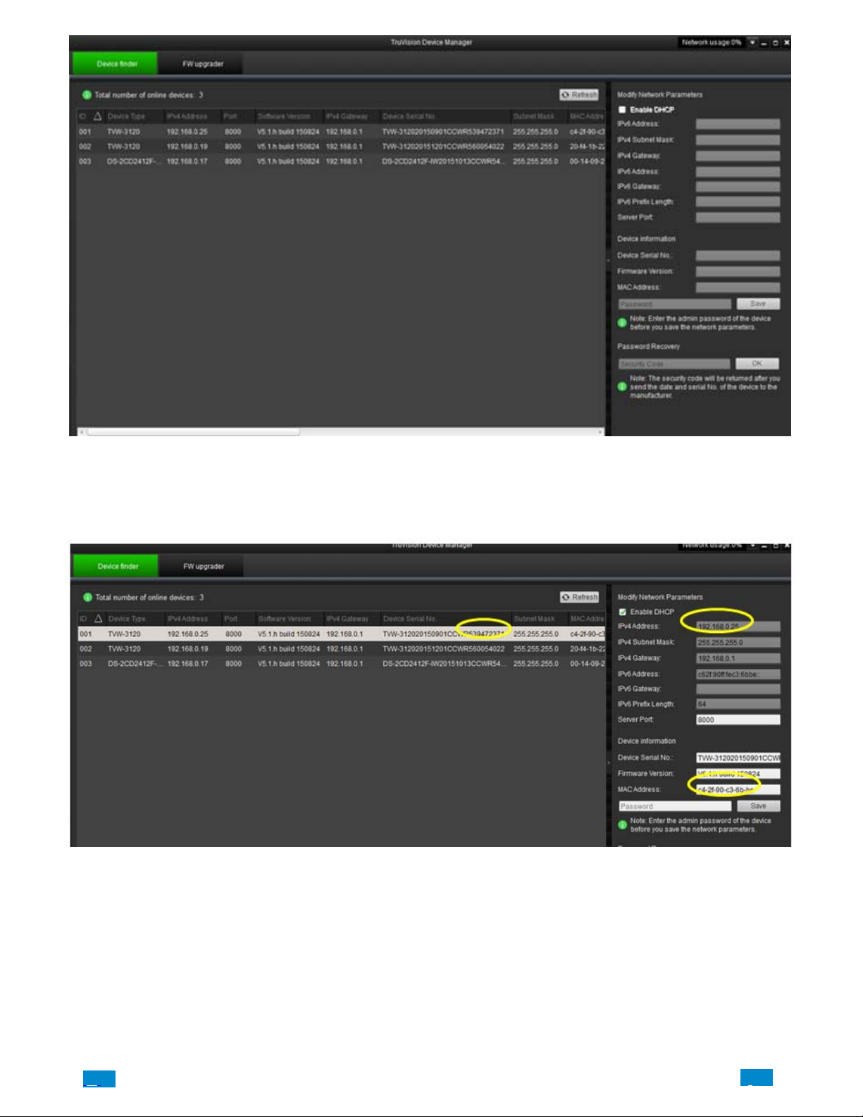
The program will list cameras that are visible on the network.
Select the camera from the list that matches the Device Serial No. displayed on the screen to the serial number of the camera. The serial
number can be located on the label of the camera box and is represented by a 9 digit number i.e. 539472371
Once you have selected the camera, the parameters of that camera will be displayed in the fields to the right of the screen. Write down the
IPv4 Address and MAC Address associated with the camera.
Step 5
Launch the web browser using the connected Router network and type the IPv4 Address of the camera in the address field and hit Enter.
.C.
58
..
.I
Page 59
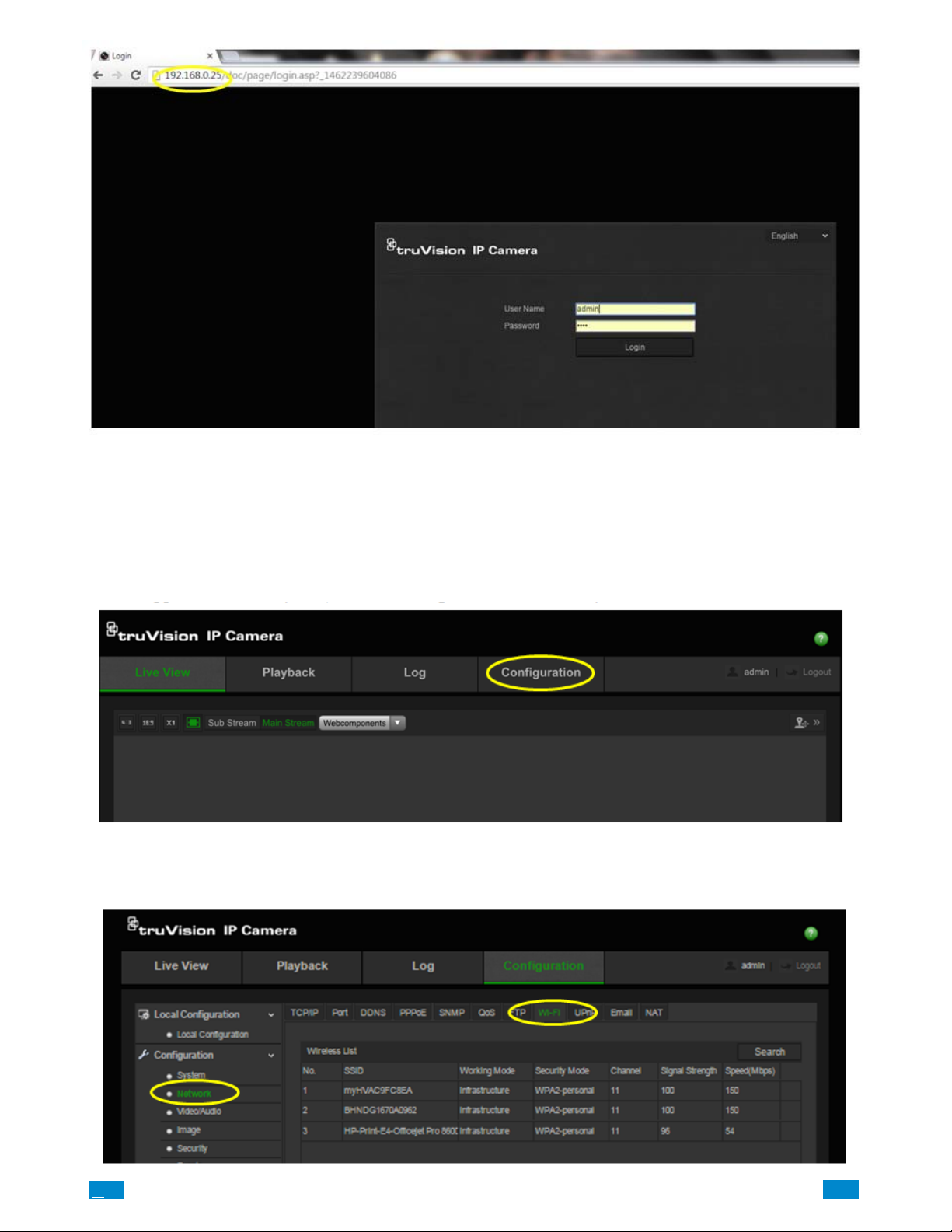
Login into the truVision IP Camera web browser using the following credentials:
User Name: admin (Case Sensitive)
Password: 1234
Step 6
Once logged into the web portal, click the Configuration tab on the top tab.
Step 7
From the Configuration menu folders listed to the left of the screen, select Network. Then select the Wi Fi tab in the Network folder.
.C
59
..
.I
Page 60
Step 8
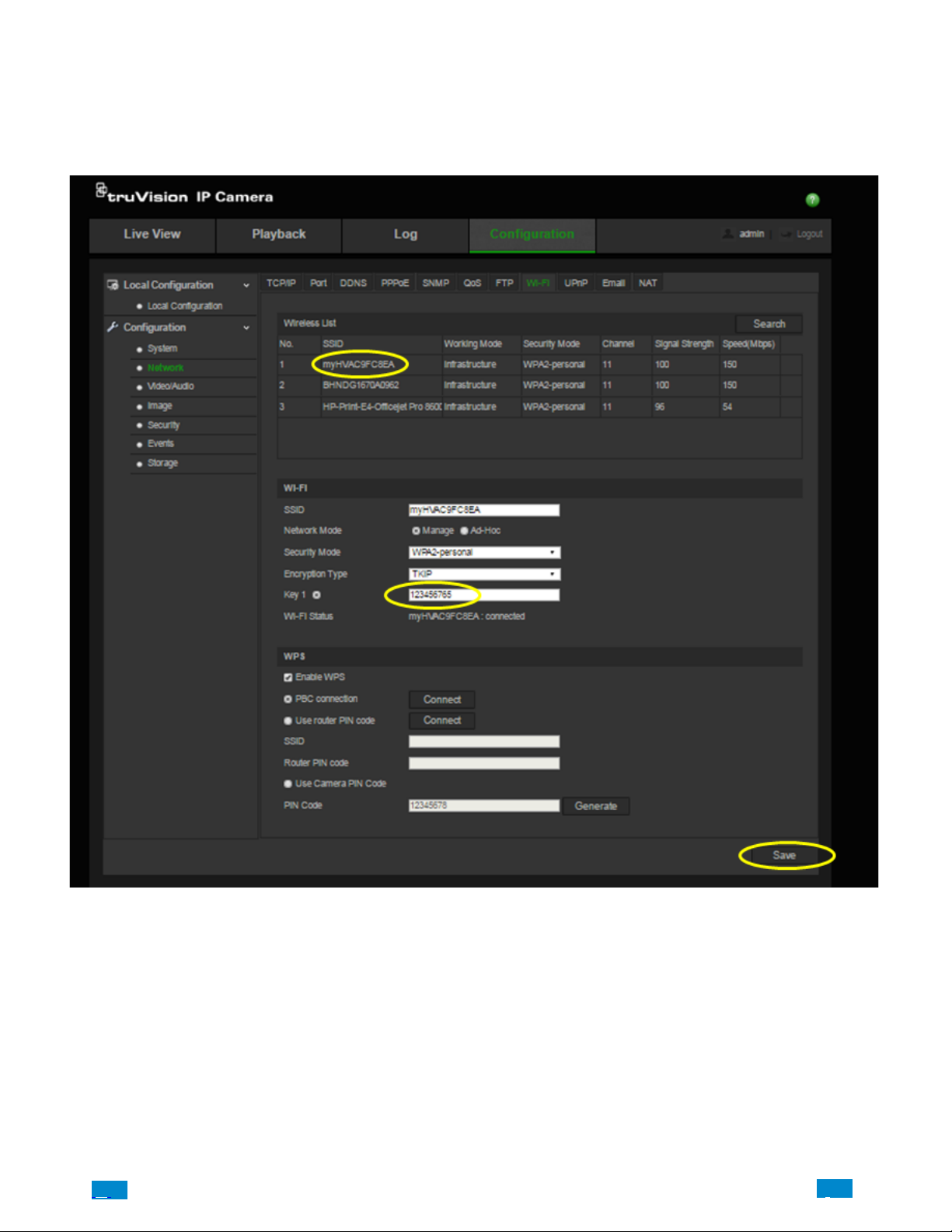
Locate and click the name of the Wi−Fi network that you wish to use from the Wireless List.
T ype the password for the Wi−Fi network that you selected in the Key 1 field box.
Press the Save button on the bottom right of the screen after you enter the Wi−Fi password.
Step 9
Login to the Côr Web Server from your laptop computer using the IP address announced from the Côr panel (Menu – 8 – [Installer PIN] –
Enter – 6).
Once logged on the Côr Web Server, select Cameras from the drop down list in the Settings menu.
In the camera section, assign a name to the camera in the Camera Name field and type in the IPv4 Address and MAC Address noted from
Step 4 in the respective fields.
Press Save after you have entered all the information.
.C.
60
..
.I
Page 61
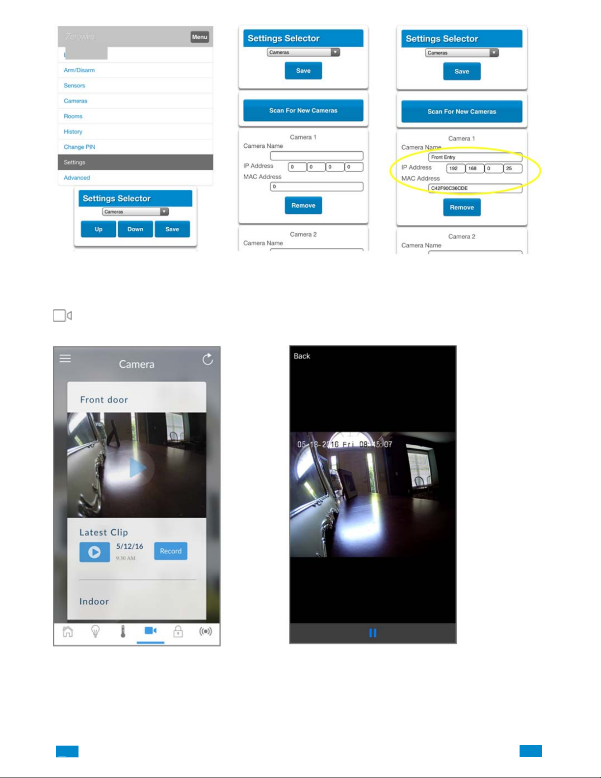
Step 10
Verify the camera is connected to the Côr Home Automation system by going to the Homeowner Côr App and pressing the camera icon
at the bottom of the menu bar to access the Wi−Fi cameras. Pressing the Play icon in the center picture of the video will allow you to
view live video streams from the camera.
You are now connected to the network via Wi−Fi!
.C
61
..
.I
Page 62
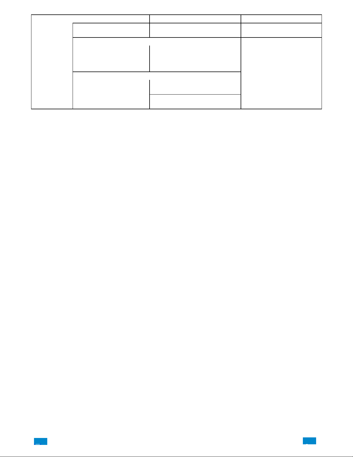
Camera Menu
Option Default Function
Scan for new cameras. -
Camera Configuration
Camera Name drop down (all
cameras)
Camera Configuration
IP Address
MAC Address
Finds cameras added to the
same IP network as Côr .
This name can be up to 32 characters.
Make sure the name matches the
name you have set up in the camera
app.
Notification
IP address assigned to the camera by
the premises network.
MAC address assigned to the camera
by the premises network.
.C.
62
..
.I
Page 63
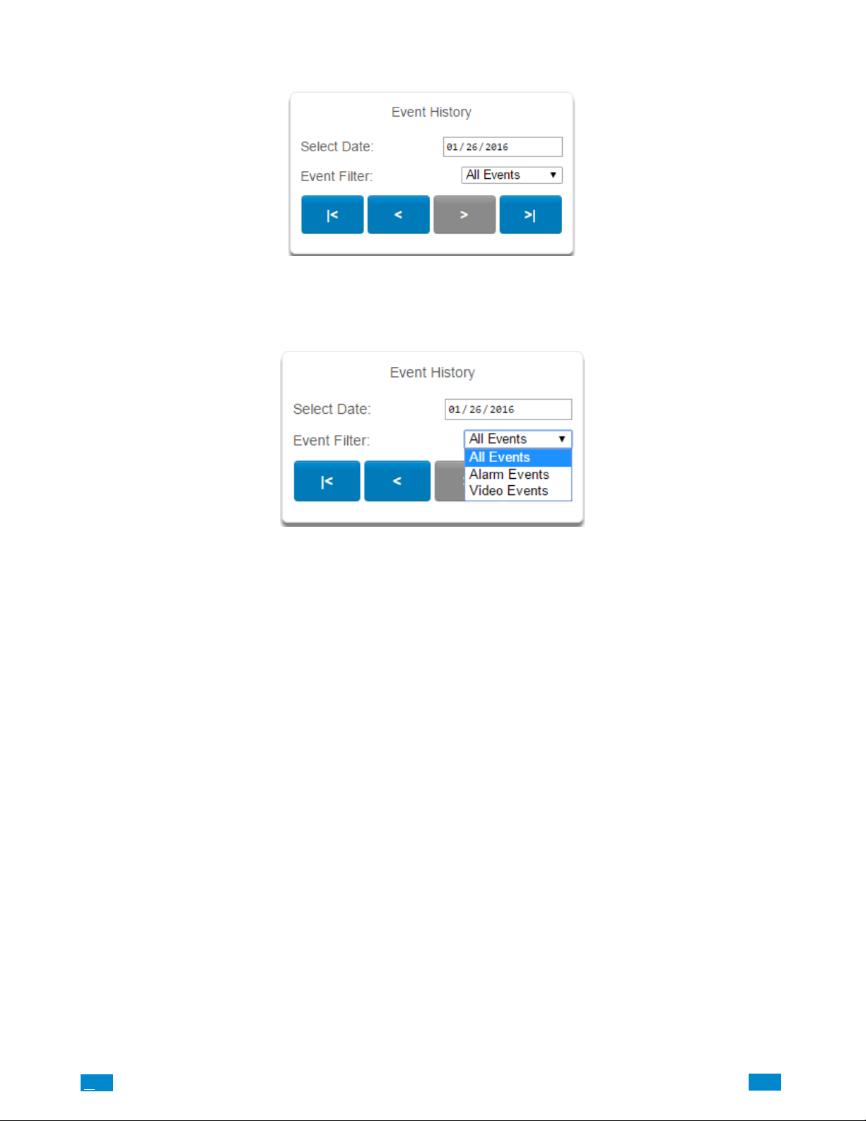
4.12 Check Event History
Côr allows you to check the history of events that have occurred in the system. Press History and this menu will appear:
Navigate to events recorded in the system with the arrow buttons. You can select the date for finding events and use the Event Filter
dropdown menus to select among alarm events or video events. The system stores 1024 alarm events and 1024 video events. The display
shows 10 events at a time.
.C
63
..
.I
Page 64
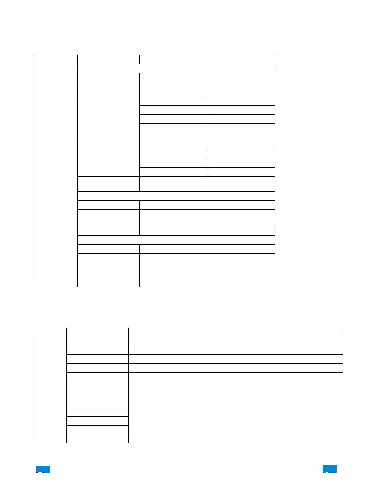
4.13 Check Connection Status
e
t
s
s
Select Connection Status from the drop down menu.
Also reference Advanced Programming, System, Section 5.1.
Connections Option Function
Connection Status
Not Linked, Configuring, Connected (Côr connection
status)
1. Getting Details 6. Configuring Protocol
2. Configuring Modem 7. Getting Echo
3. Modem Connected 8. Connected
4. Configuring PPP 9. Terminating
5. Authenticating 10. Idle
1. Idle 5. Retry Delay
2. Selecting Service 6. Getting Server Hello
3. Making Connection 7. Connected
4. Disconnecting
WPA2 + AES
WPA + AES
WPA + TKIP/AES
WPA + TKIP
WEP
Connection
Status
Menu
LAN Status
LAN Media Wi Fi, Ethernet (method of Côrconnection)
Cell Stat
Ultra Connec
(UltraSync) Statu
UltraConnect
(UltraSync) Media
Radio Details
Cell Service No Service, Restricted Service, Valid Service
Signal Strength −113 to −51
Operator ID
Radio Technology GSM, UMTS
WI FI Details
WI FI SSID
WI FI Security T ype
Notification − Diagnostic
Wireless, LAN
4.14 Check Details
Select Details from the drop down menu.
Device Details Details
Control Name
Device UID (Serial) Serial number of the Côr panel
Ethernet MAC Address Ethernet MAC address assigned to the Côr panel by the premises network
WI FI Mac Address WI FI MAC address assigned to the Côr panel by the premises network
Control Model
Detail Statu
.C.
Firmware Version
Hardware Version
Bootloader
Voice Version
W ebsite Version
Memory Map Version
Menu String Version
of the Côr panel
64
..
.I
Page 65
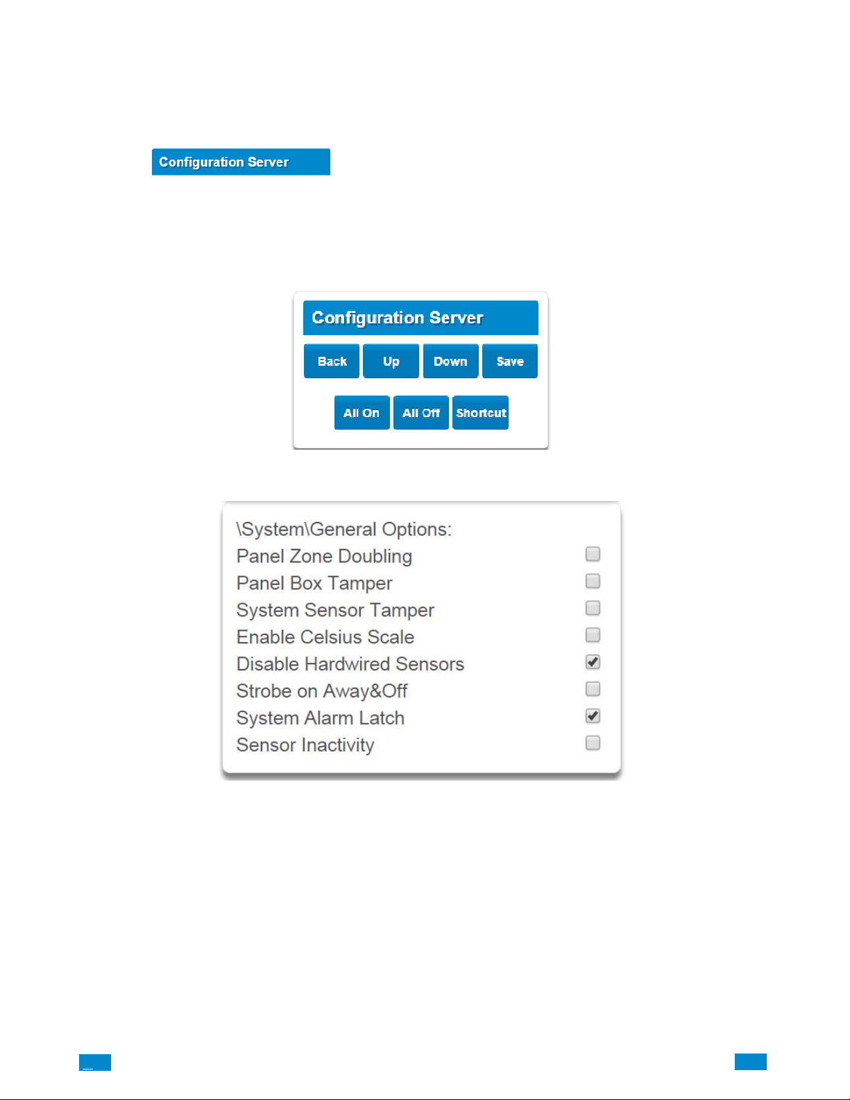
5 ADVANCED INSTALLATION USING WEB SERVER
Advanced settings are only accessible via the Côr Web Server from your computer using the IP address announced by pressing Menu 8−
[Installer PIN] − 6, UltraSync app, or DLX900.
After loging into the Côr Web Server, press the Menu button then select Advanced from the drop down list.
You are on the
The Configuration Service page main tile contains different buttons than the settings tile.
BACK: Moves you back to the main selection.
UP: Moves you up one option through the programming options.
DOWN: Moves you down one option through the programming options.
ALL ON / ALL OFF: Allow you to select or deselect all the check boxes in menus like below.
page.
.C
65
..
.I
Page 66
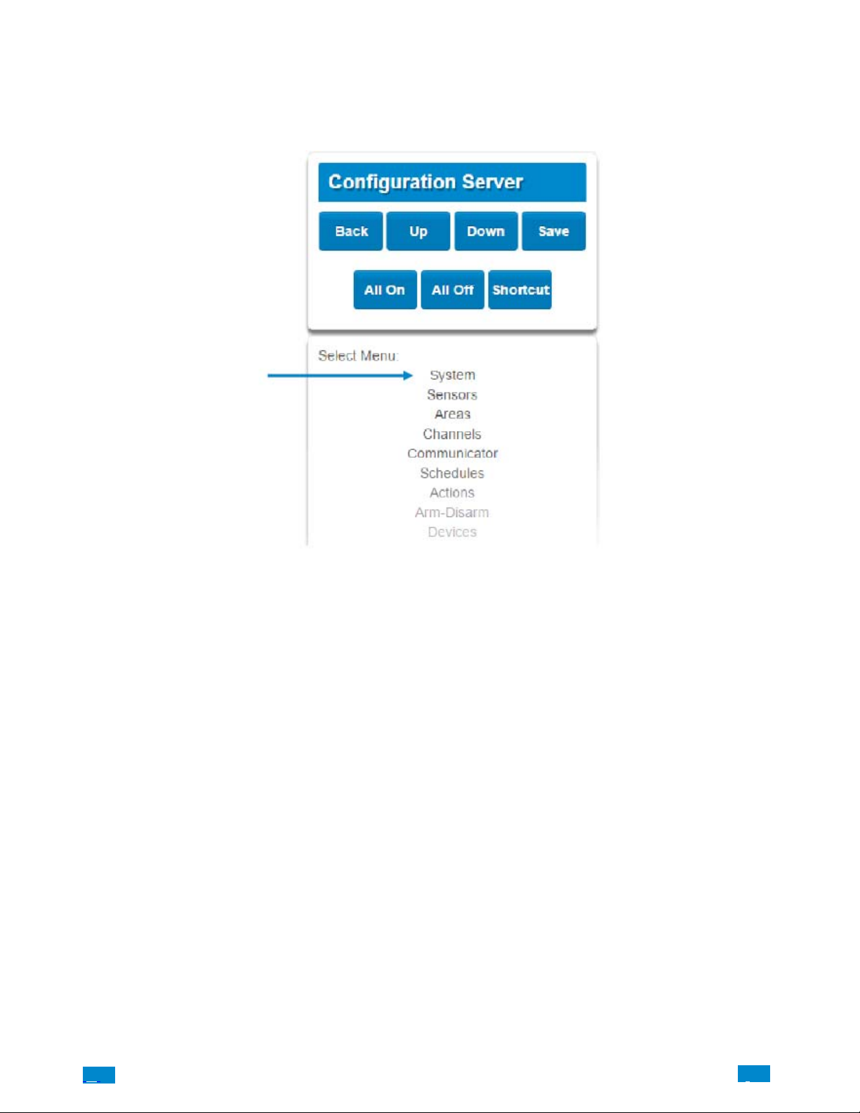
5.1 Advanced Programming, System
Select System from the menu.
System Options is used to configure system wide options, such as time and dates, system timers and maintenance.
.C.
66
..
.I
Page 67
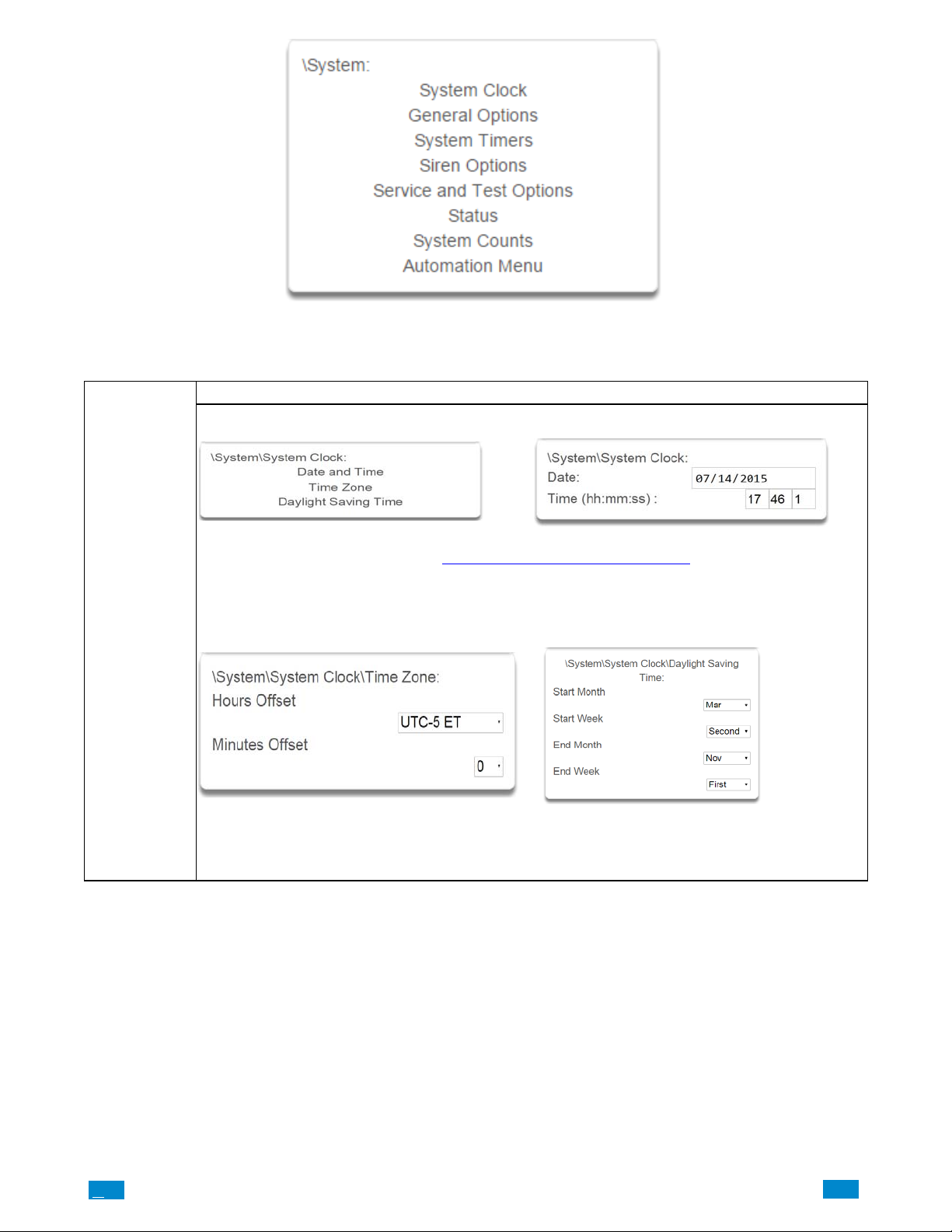
System Clock
System Submenus
1 System Clock 2 Clock Date and Time
When connected to an IP network the Côr system clock synchronizes its time and date automatically with
an Internet Time Server if configured in Advanced Programming, Communicator.
The Côr system clock can manage day, time, time sensor, and day light saving time settings to ensure
ongoing accurate time.
3 Time Zone Hours Offset / Minutes Offset 4 Daylight Saving Time
Start Of DLST – Month 1 to 12 of year; Week of
month 1 to 4 and last
End Of DLST– Month 1 to 12 of year; Week of month
1 to 4 and last
.C
67
..
.I
Page 68
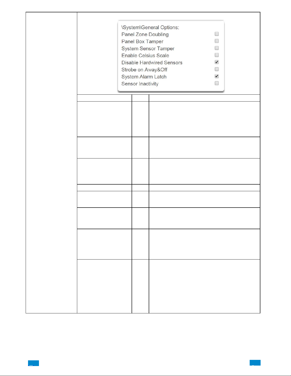
System General Options
1 General Options
Option Default Function
If enabled, the two (2) hardwired sensor inputs will be
double to support four (4) sensors. The terminals for Sen
sor 1 will represent sensors 1 and 3, and the terminals for
Panel Sensor Doubling Off
Panel Box Tamper Off
System Sensor Tamper Off
Enable Celsius Off Enable Celsius vs. Fahrenheit Scale.
Disable Hardwire Sensors On
Strobe on Away Off
System Alarm Latch On
Sensor Inactivity Off
sensor 2 will represent sensor 2 and 4. This option can
not be selected for sensors other than the two sensors on
the main panel. This option cannot be used in conjunc
tion with the DEOL option.
The Côr panel has a built-in normally closed tamper
switch that will sound the siren if the panel is removed
from the wall. This option will enable or disable this tam
per switch.
If enabled, the Côr panel will monitor all sensors, ex
cept fire sensors, for Dual End of Line (DEOL). A short or
open circuit on a DEOL will activate sensor tamper
alarms. This feature cannot be used if Panel Sensor Dou
bling is enabled.
If enabled, the Côr panel will disable all hardwired sen
sor inputs. To utilize the hardwired sensors on the back of
panel you must disable this feature.
If enabled, the system strobe will flash when an area is
set in away mode. The strobe outputs must be config
ured follow the area alarm event condition. The strobe is
not activated on Disarm or Stay.
If enabled, system alarms such as tampers, low battery,
A/C fail and trouble requires a user with “Reset System
Alarms” enabled in their current Permission Options to
reset the alarm condition.
If disabled, system alarms do not latch and can be reset
when a user arms or disarms an area.
If enabled, the Côr system will monitor each sensor for
activations. If no activations occur within the sensor activ
ity time then a failed sensor activity report may be report
ed via the selected communication channel and a failed
sensor activity message set in the Côr event log. For a
sensor to be eligible for activity monitoring, it must have
“Sensor Activity” set in sensor options.
Sensors programmed with Sensor Inactivity in the Sensor
Options must be open and closed within the time pro
grammed here (in minutes). If they do not, a Sensor Inac
tivity will report.
.C.
68
..
.I
Page 69
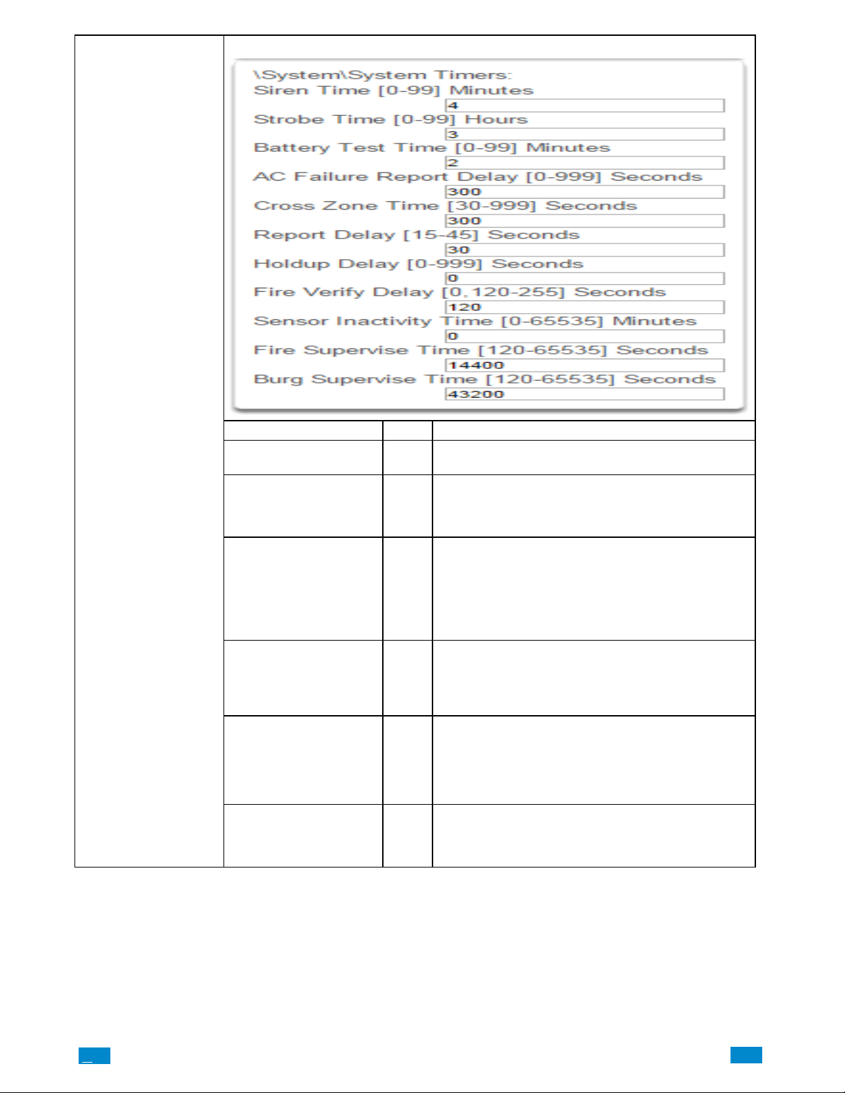
System Timers
1 System Timers
Option Default Function
Siren Time (0-99) Minutes 4
Strobe Time (0-99) Hours 3
Battery Test Time
(0-99) Minutes
AC Failure Report
Delay (0-999) Seconds
Cross Zone Time (30-999) 300
Report Delay
(15-45) Seconds
2
300
30
The siren time sets the time in minutes that the siren out
put is active
The strobe time is the duration in hours that output pro
grammed to follow the strobe time will activate. The valid
time selection in this segment is 0 to 99 hours, where ‘0’
disables the Strobe Output.
The dynamic battery test time sets the duration in min
utes that the Côr will perform a dynamic battery test.
The Côrwill perform a dynamic battery test at the dis
arming of the first area or at midnight once each
24-hour cycle. Dynamic battery test is disabled when
the test duration is set to 0. Dynamic battery test can also
be run manually from a keypad.
The AC fail report delay sets the duration in seconds that
the AC power is lost or restored before a communication
is initiated.
AC restore will report when power is maintained for this
same duration.
The Cross Zone Time sets the duration in seconds
whereby two or more sensors must trip before an alarm
condition will be registered or the one sensor must trig
ger twice within this time period, or a continuous trip
longer than 10 seconds. This feature only applies to sen
sors with the Cross Zone feature set in sensor options.
The report delay is the duration in seconds that non-24
hour and non-fire type sensors will delay before report
ing. This provides a valid user the opportunity to reset an
unintended alarm condition before that event is reported
.C
69
..
.I
Page 70
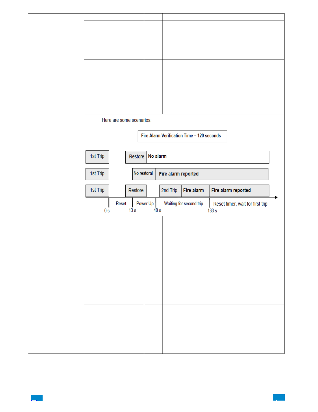
Option Default Function
Holdup Delay
(0-999) Seconds
Fire Verify Delay
(0,120-255) Seconds
The holdup delay is the duration in second that a holdup
delay sensor type will wait before it activates. If additional
holdup activations occur during the holdup delay period
then the holdup delay will immediately expire and set the
0
holdup alarm. If a holdup delay sensor type is de-acti
vated during the holdup delay period then the holdup
alarm will reset and not activate.
The fire alarm verification feature is designed to reduce
false alarms reported by smoke detectors.
The Côr will wait 40 seconds to allow the smoke sensor
to power up and settle. If a second trip occurs after this
but before the end of the Fire Verify Delay time, a fire
120
alarm will be generated. If no restoral is received after the
first trip, a fire alarm will also be generated. The valid time
selection in this segment is 120 to 255 seconds. The
communicator will delay for a specified time before re
porting the fire alarm
System Timers
Sensor Inactivity
Time
(0-65535) Minutes
Fire Supervise Time
(120-65535)
Seconds
Burg Supervise Time
(120-65535)
Seconds
0
14400
14400
Sensors programmed with Sensor Inactivity in the Sensor
Options must be open and closed within the time pro
grammed here (in minutes). If they do not, a Sensor Inac
tivity will report. This feature can be enabled in “System
Options”. See Section4.4.
Default Sensor Inactivity option is off and this timer is set
to 10080 minutes (7 days).
This applies only to wireless sensors programmed as fire
type. Sensors send a reduced packet count supervisory
signal every 60 minutes (check your sensor manual for
most up to date details). If no supervisory signal is re
ceived by the panel within the time specified here then
the sensor will be reported as missing.
When set to 0 the default of 14,400 seconds (4 hours) will
be used. Check your local regulations for the correct val
ue to use.
This applies only to wireless sensors programmed as
non-fire type. Sensors send a reduced packet count
supervisory signal every 60 minutes (check your sensor
manual for most up to date details). If no supervisory
signal is received by the panel within the time specified
here then the sensor will be reported as missing.
When set to 0 the default of 43,200 seconds (12 hours)
will be used. Check your local regulations for the correct
value to use.
.C.
70
..
.I
Page 71
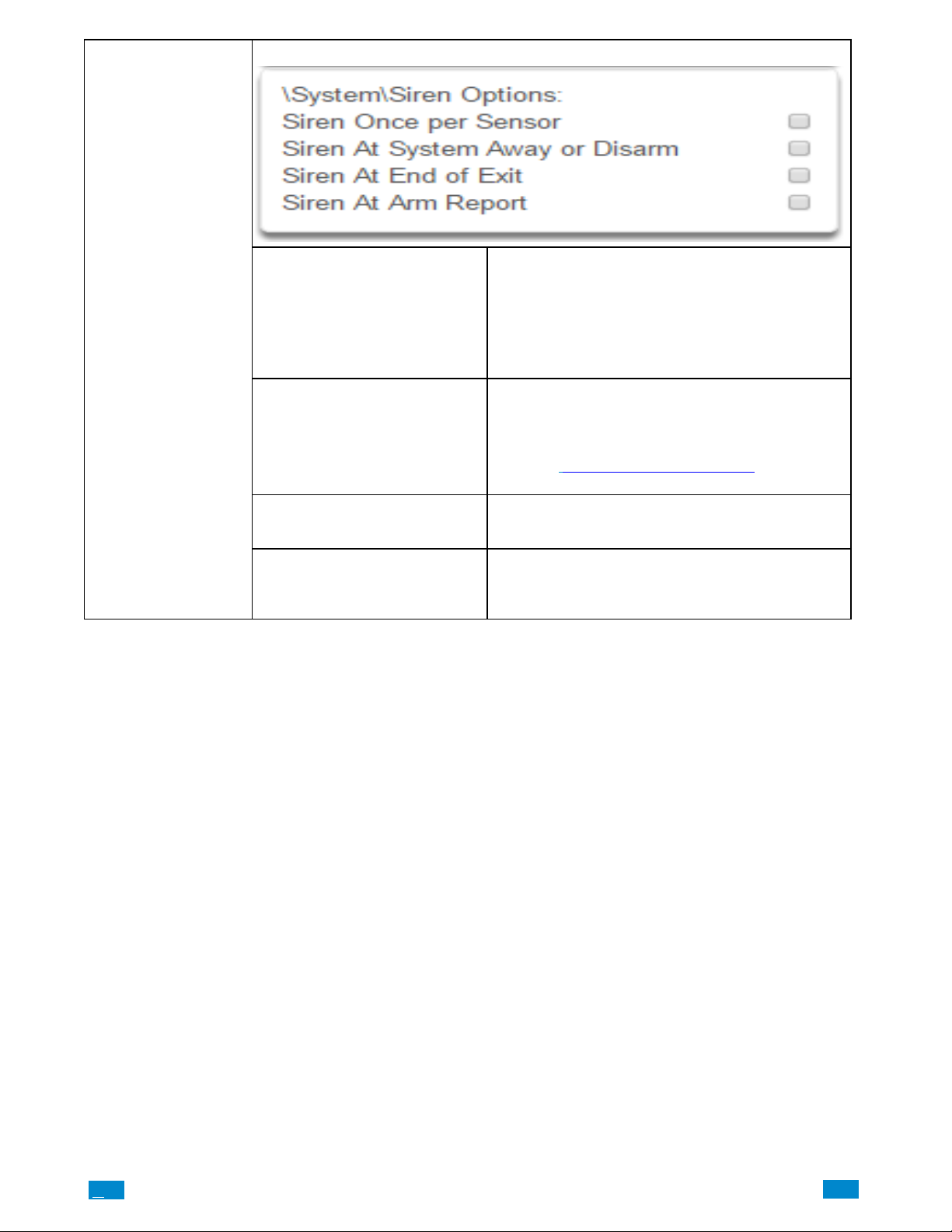
System Siren Options
1 Siren Options
Siren Once Per Sensor
Siren At System Away/Dis
arm
Siren At End Of Exit
Siren At Arm Report
If enabled, the Côr panel will only activate the siren
once per sensor in a given arm cycle and will not activate
the siren again even if that siren time expires and that
sensor reactivates. Every sensor will have one siren acti
vation attempt before that sensor cannot reactivate the
siren. If this option is not enabled, at the expiry of the
siren time any sensor can reactivate the siren an unlimit
ed number of times.
If enabled, the Côr panel will activate the built-in siren
briefly each time the last area in the system is set in away
mode or when the first area is disarmed. To enable this
function by area, leave this option disabled in this sec
tion, and enable the “Siren at System Away/Disarm” in
section 5.3
you require.
If enabled, the Côr panel will activate the built-in siren
briefly each time the system is set in away mode and the
exit delay expires.
If enabled, the Côr panel will activate the built-in siren
briefly every time the system is set in away mode, the exit
delay expires and a successful system arm report is com
pleted.
Advanced Programming, Areas for the area(s)
.C
71
..
.I
Page 72
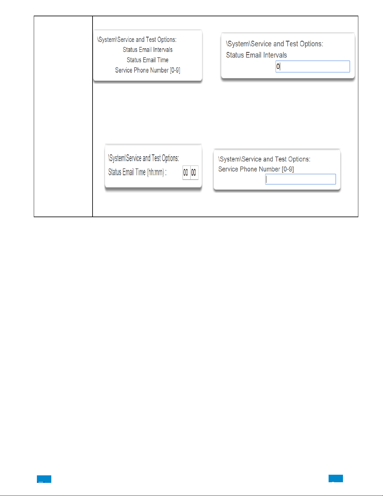
System Service and
Test Options
1 Service and Test Options 2. Email Intervals
If enabled, Côr will report a system status email via one
or more email channels. The number entered for Status
Email Interval is the number of days between status re
ports. For example entering a 7 will cause a report to be
sent every 7 days.
The interval starts from either the first time a program
interval is entered or when the system is powered up.
3 Email Time 4 Service Phone Number
The status email time sets the time of day
that the status email will report. This is set
as 24-hour time in hours and minutes.
When a system condition needs repair, this number will
be announced to the end-user. Typically this is the in
stallation company.
.C.
72
..
.I
Page 73
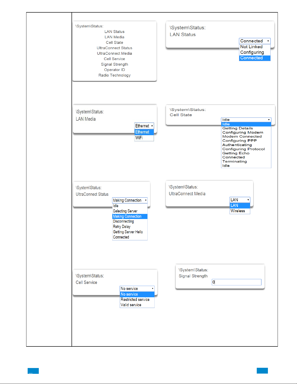
1 Status 2. LAN Status
This menu provides diagnostic information
on the connection status of the xGen.
3 LAN Media 4 Cell State
System Service and
Test Options
5 UltraConnect Status (UltraSync) 6 UltraConnect Media (UltraSync)
Status of the connection to the cloud
servers.
7 Cell Service 8 Signal Strength
When connected to the cellular radio net
work this will display what level of service is
provided. If the optional radio module is
installed with a valid SIM card, and this
shows restricted service, please contact
your service provider as your SIM card may
not be provisioned correctly.
If the optional radio module is installed with a valid SIM
card, this will show the numeric signal level.
If the reported value is -113 to -89 then installing an
external antenna is recommended. If the reported value
is -89 to -51 then the signal strength is OK.
.C
73
..
.I
Page 74
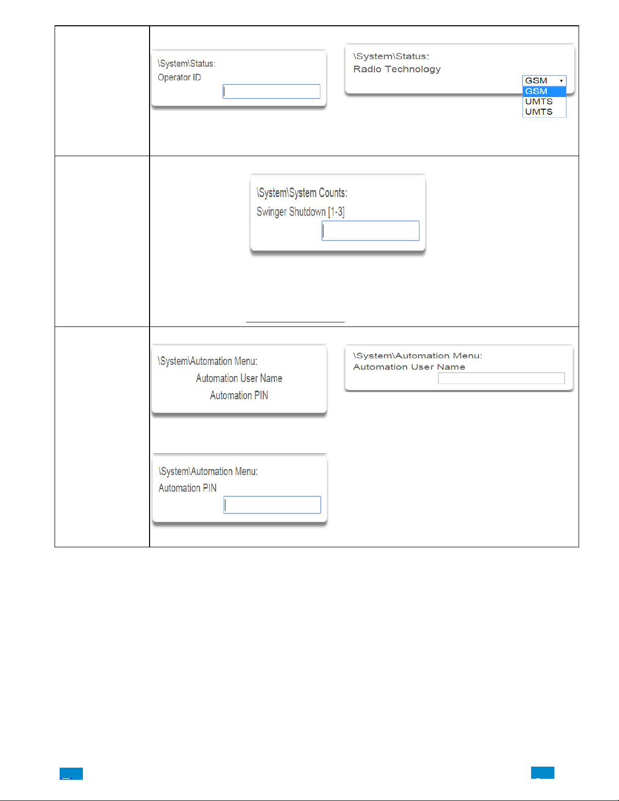
System Status
9 Operator ID 10 Radio Technology
System Counts
If the optional radio module is connected to
the network this will display the ID of the
network operator
1 Counts
Swinger Shutdown is a false alarm prevention feature prevents a single sensor from activating more than
a programmed number of times during a single arming period. After a certain number of alarms caused
by the same sensor within the same arming period, the Côr will then shutdown that sensor for the re
mainder of that arming period. The sensor will be reactivated when the system is disarmed or rearmed to
any security mode.
See SIA CP-01-2010 Programmable Features
1 Automation Menu 2 Automation User Name
If the optional radio module is connected to the
network this will display the connection technology
such as GSM or UMTS.
Table for reference.
System Automation
Menu
Used when there is API integration.
3 Automation Pin
Used when there is API integration.
.C.
74
..
.I
Page 75
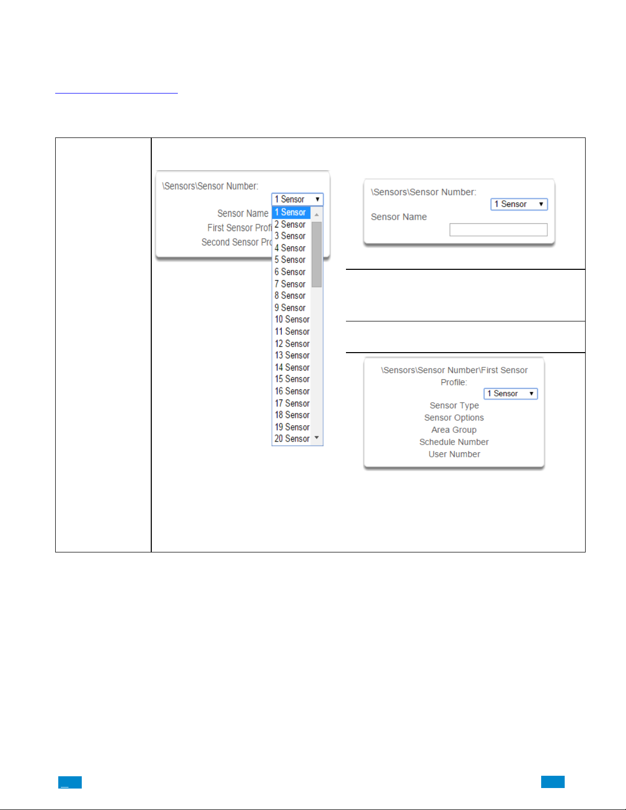
5.2 Advanced Programming, Sensors
From the Advanced drop down list, select Sensors from the menu.
A sensor (sometime referred to as a zone or input) is a single physical hardwired connection or a non−physical wireless connection.
Additionally sensors on the Côr system can be used as logic inputs within actions and / or be configured as one of many sensor types. See
Advanced Programming, Actions.
IMPORTANT: After you have finished programming a sensor, be sure to advance the sensor number in the drop down menu when
programming the next sensor. Otherwise you will over−write the sensor configuration you just programmed.
Sensor Submenus
1 Sensor Number 2 Sensor Name
Each sensor can be configured with a custom 32 charac
ter name. The sensor name is displayed wherever a sen
sor is referenced on the Côrsystem.
3. First Sensor Profile
Sensor Submenus
The Côr panel can support a total of 64
sensors. Each sensor is identified by a
unique sensor number, which cannot be
altered, and remains as the key reference
for each sensor.
Sensor profiles determine the sensor type (Entry, 24 hour,
fire, key switch, etc.) and the sensor options (bypass,
force arm, twin trip, stay mode, etc.). Sensor profiles also
determine the area in which the sensor resides in. Addi
tionally, each profile has a schedule that Côr uses to
determine which of the two sensor profiles to use and
when to use them.
.C
75
..
.I
Page 76
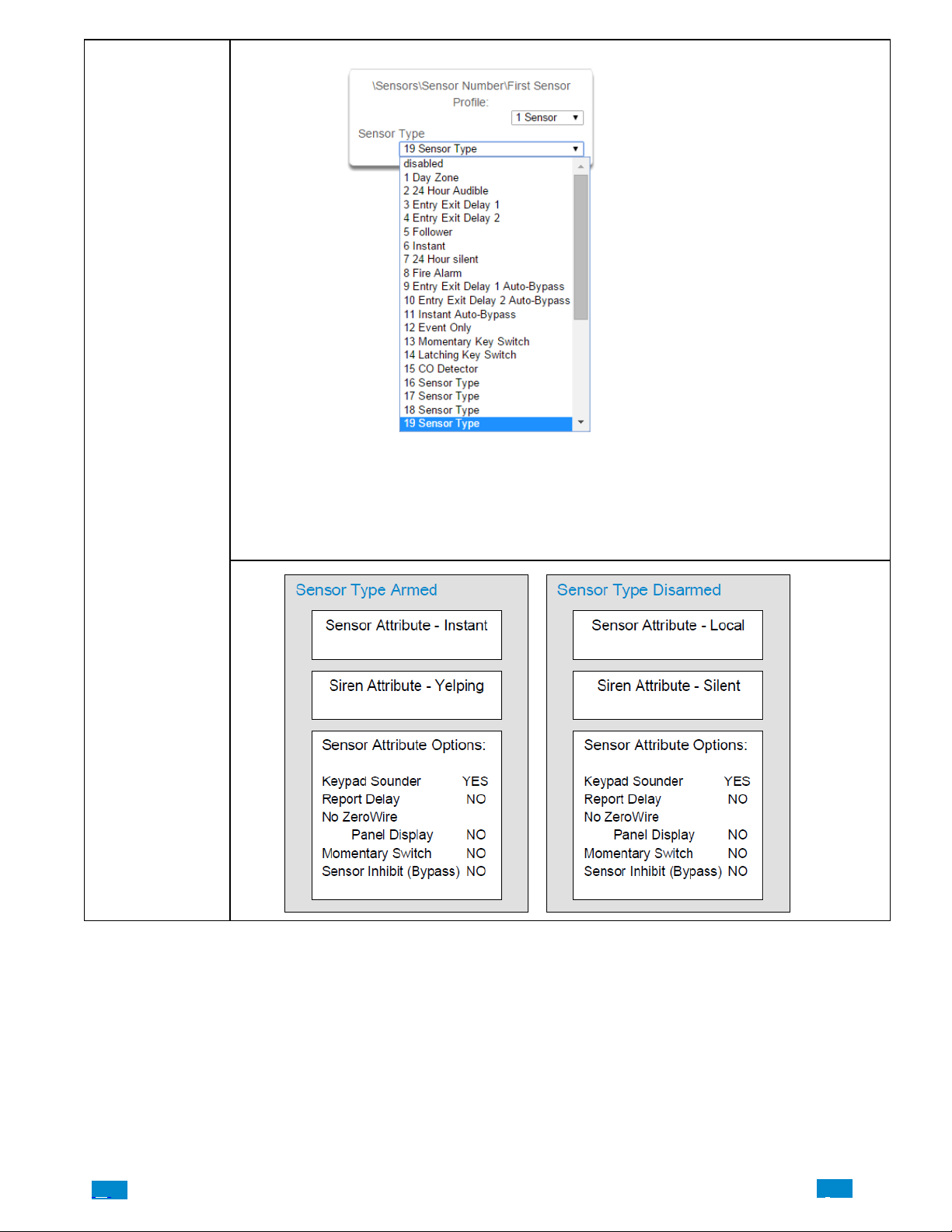
Sensor Submenus
4 Sensor Type
One of 32 configurable sensor types may be allocated to any sensor’s sensor type. Each sensor type can
behave independently between an arm and disarmed state. Sensor types determine the sensor attributes,
siren attributes, and sensor attribute options.
Here is an example of a preset sensor type:
Sensor Type – 1 – Day Sensor
.C.
76
..
.I
Page 77

5 Sensor Options 6 Area Group (1-16)
One of 16 configurable area groups can be allocated to
any sensor’s area group. Area groups are a list of Côr
areas. When an area group is allocated to a sensor, that
sensor will then belong to all the areas in the area group.
If a sensor is assigned to multiple areas it will not arm
until the last area is armed. It will also be disarmed when
the first area is disarmed.
Ensure the correct Area Group is assigned to a sensor. If
an area Group with no areas is used, then the sensor will
never report.
7 Schedule Number
Sensor Submenus
One of 32 configurable sensor options may
be allocated to any sensor’s sensor op
tions. Sensor options determine the sensor
attributes such as a sensor’s ability to be
bypassed, force arm, cross zone, stay
mode, etc. Additionally sensor options de
termine the sensor’s reporting attributes.
One of 16 configurable schedules can be
allocated to any sensor’s schedule number.
Sensor profile schedules determine when
to allocate a sensor profile to a sensor. The
first sensor profile has the highest priority
and the second sensor profile has the low
est priority.
The panel will check if the current time and
day fall within the schedule of the first sen
sor profile or if the schedule is disabled
(thus always active). If the schedule is ac
tive then that profile is applied to that sen
sor.
If the first sensor profile’s schedule is not
active then it will check the second sensor
profile. If the schedule is active then that
profile is applied to that sensor.
.C
77
..
.I
Page 78
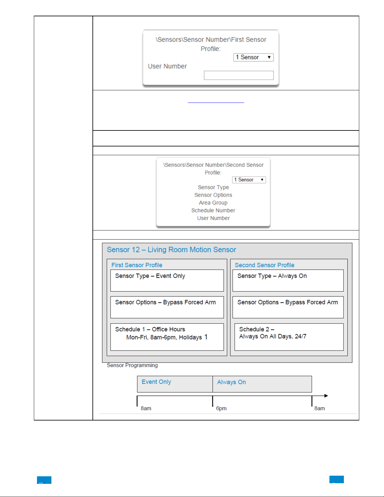
8 User Number
The sensor user number feature is used whenever the sensor type is set to “keyswitch”. Instructions for
users configuration are in Section 6 – Users and Permissions. One of 40 configurable users can be allocat
ed to any sensor’s user number. Côrsensor profile user number is a powerful feature that is used to ap
ply the selected user’s attributes to a keyswitch operation. When the keyswitch sensor is activated, Côr
will check the user permissions and permission schedules to determine which areas are accessible. Addi
tionally, area open and close reports will also report the user number selected in this option
NOTE: If the user number is programmed to 0, the Côr will use a default User number of 999 and will
operate on all areas in the sensors area group.
9 Second Sensor Profile (Refer to First Sensor Profile)
Sensor Submenus
Example Diagram
.C.
78
..
.I
Page 79
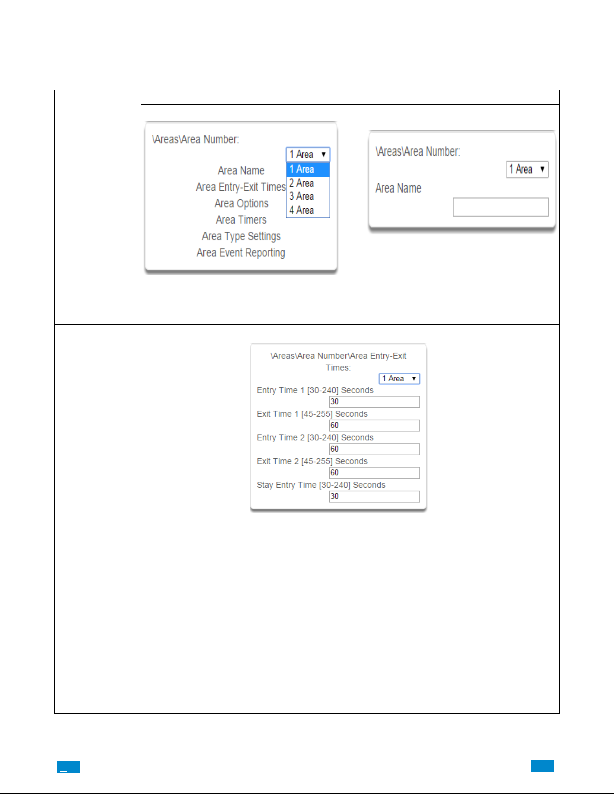
5.3 Advanced Programming, Areas
Select Areas from the drop down menu.
1 Area Number 2 Area Name
Areas Submenus
Areas Submenus
Areas Submenus
The Côr panel can support a total of 4 areas. Each
area is identified by a unique area number, which cannot be altered, and remains as the key reference for
each area.
3 Area Entry−Exit Times
Côr uses the area entry and exit timers to delay the activation of an alarm event when entry/exit sensor types are
activated.
When an area is turned on, it will start an Exit 1 timer. While an Exit 1 timer is running – Entry 1, Entry 2, and
Follower sensor types will not create an alarm.
When the Exit 1 timer expires it will start the Exit 2 timer. While an Exit 2 timer is running – Entry 2 sensors will
not create an alarm.
Once all exit delays are expired, an activation on an Entry 2 sensor type will start an Entry delay with the Entry 2
time, and an activation of an Entry 1 sensor type will start an Entry delay with the Entry 1 time.
If an entry delay is running and a sensor is activated with an entry time that is less than the time remaining, the
timer will be reduced to the time of that new sensor.
Activation of a Follower sensor while an entry timer is not running will create an instant alarm.
If a sensor is in more than 1 area, the sensor will use the have the longest entry and exit delay time of the pro-
grammed area. If an area greater than 1 has the time set to 0, that area will use the time programmed in Area 1.
Stay Entry Time
The stay entry time is the entry warning time that applies to all sensors armed in the stay mode. Entry 2 sensors will
follow Entry 2 time and will ignore this setting. This stay entry time does not apply to any 24 hour sensor types.
Each area can be configured with a custom 32 character name. The area name is displayed wherever an
area is referenced on the Côr system.
.C
79
..
.I
Page 80
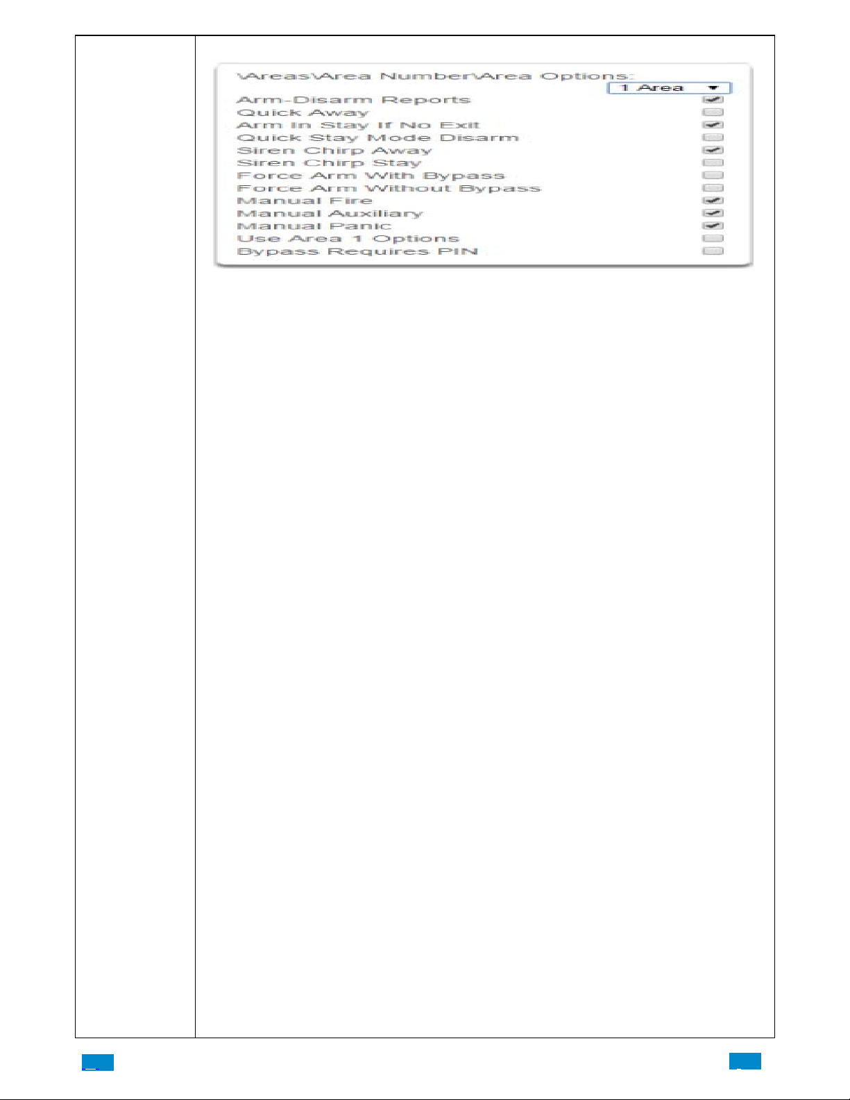
Areas Submenus 4 Area Options
1. Arm/Disarm Reports
If enabled, this area will send open and close reports via one or more appropriately configured channels.
2. Quick Away
If enabled, this area can be armed in away mode via a single away mode key press. When an area is armed via
quick away mode, the closing user number is the default user of 999
3. Arm In Stay If No Exit
If enabled, Arm In Stay If No Exit will cause this area to arm in stay mode even when a user arms it in away mode,
providing that an entry 1 or entry 2 sensor type is not triggered during the exit delay.
4. Quick Stay Mode Disarm
If enabled, this will allow the stay mode to be disarmed by pressing the stay key on the keypad. This is only possible if there is no alarm active and the stay entry delay is currently running.
At the end of the stay entry delay or if there is an area alarm, the stay mode can only be disarmed via a valid user
PIN.
5. Siren Chirp Away
If enabled, Côr will activate the built−in siren briefly each time this area is set in away mode or disarmed with a
key−switch sensor or wireless keyfob.
Areas Submenus
6. Siren Chirp Stay
If enabled, the Côr will activate the built−in siren briefly each time this area is set in stay mode with a key−switch
sensor or wireless keyfob.
7. Force Arm With Bypass
If enabled, the area can be armed even if sensors are not ready. Any sensors that are not ready will automatically be
bypassed. The bypass will be logged in the event history.
The automatic bypass will be applied when the sensor is capable of causing an alarm condition due to a state
change such as an area arming, schedule or action. This avoids false alarms.
If an auto−bypassed sensor becomes ready after it is armed, that sensor will automatically remove the bypass, log
the bypass restore, and optionally report the bypass restore.
Individual sensors can be made “force armable with auto−bypass” by leaving this area option off, then enabling
Forced Arm Enable in Sensor options, and enabling Sensor Inhibit (Bypass) in the Sensor Type Profile.
8. Force Arm W ithout Bypass
If enabled, the area can be armed even if sensors are not ready. Any sensors that are not ready will NOT be automatically be bypassed and may cause an alarm condition because they could still be in a not ready state once the
area becomes armed.
This option is overridden if the Force Arm With Bypass is enabled.
Individual sensors can be made “force armable without auto−bypass” by leaving this area option off, then enabling
Forced Arm Enable in Sensor options, and disabling Sensor Inhibit (Bypass) in the Sensor Type Profile.
9. Manual Fire
If enabled, the manual fire button will be enabled on keypads. Press and hold for 2 seconds to send a fire event.
Default is on.
10. Manual Auxiliary
If enabled, the manual auxiliary button will be enabled on keypads. Press and hold for 2 seconds to send an auxiliary event. Default is on.
11. Manual Panic
If enabled, the manual panic button will be enabled on keypads. Press and hold for 2 seconds to send a panic event.
Default is on.
12. Use Area 1 Options
If enabled, the area will use Area 1 options. Default is on.
13. Bypass Requires PIN
If enabled, a valid PIN code with access to this area is required to bypass sensors in this area.
.C.
80
..
.I
Page 81
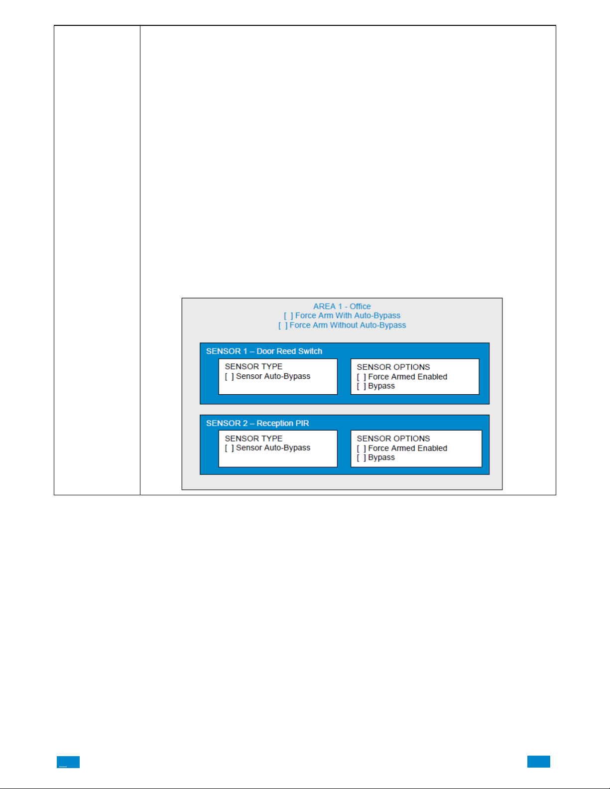
Areas Submenus
Notes on Force Arming, Bypass, and Auto−Bypass
Normally to arm an area it must first be “Ready to Arm”. This means all sensors in that area must be closed.
For example, if the front door is open, then a user would need to close it first and ensure there is no movement in
the reception area. This provides the Ready to Arm status in Area 1 that is needed before attempting to arm. This is
not always user friendly or practical.
The term force arm refers to the ability to arm an area even though sensors are not ready. It is usually only used
with motion sensors as these are self−restoring and will be restored by the time the exit delay ends (e.g. the person
arming the system leaves the building causing the Reception PIR to restore.)
If the front door is not closed properly then Area 1 would go into alarm at the end of the Exit time. To avoid this
false alarm we enable “Force Arm With Auto−Bypass” so all sensors that are not closed (i.e. not ready) by end of
the exit time will be “Auto−Bypassed”.
If after the Area is armed, that sensor restores (e.g. the person double checks and secures the front door) then the
Auto−Bypass will be removed from the sensor and it will be active. If subsequently the sensor is triggered then
Area will go into alarm.
Auto−bypass will be applied (if enabled, and if necessary) to a sensor whenever a change in state occurs that would
result in an alarm condition. These include arming an area with a not−ready sensor, a sensor changing profile,
Arm−Disarm function, or due to an action or schedule.
Enabling Auto−Bypass for the area will apply the feature to all sensors in that area as well.
In general disabling “Sensor Auto−Bypass” is not recommended because of the potential to create a false alarm
but there are applications where it is desired. Use “Force Arm Without Auto−Bypass” at the area level to prevent
sensors from being auto−bypassed when Force Armed.
.C
81
..
.I
Page 82
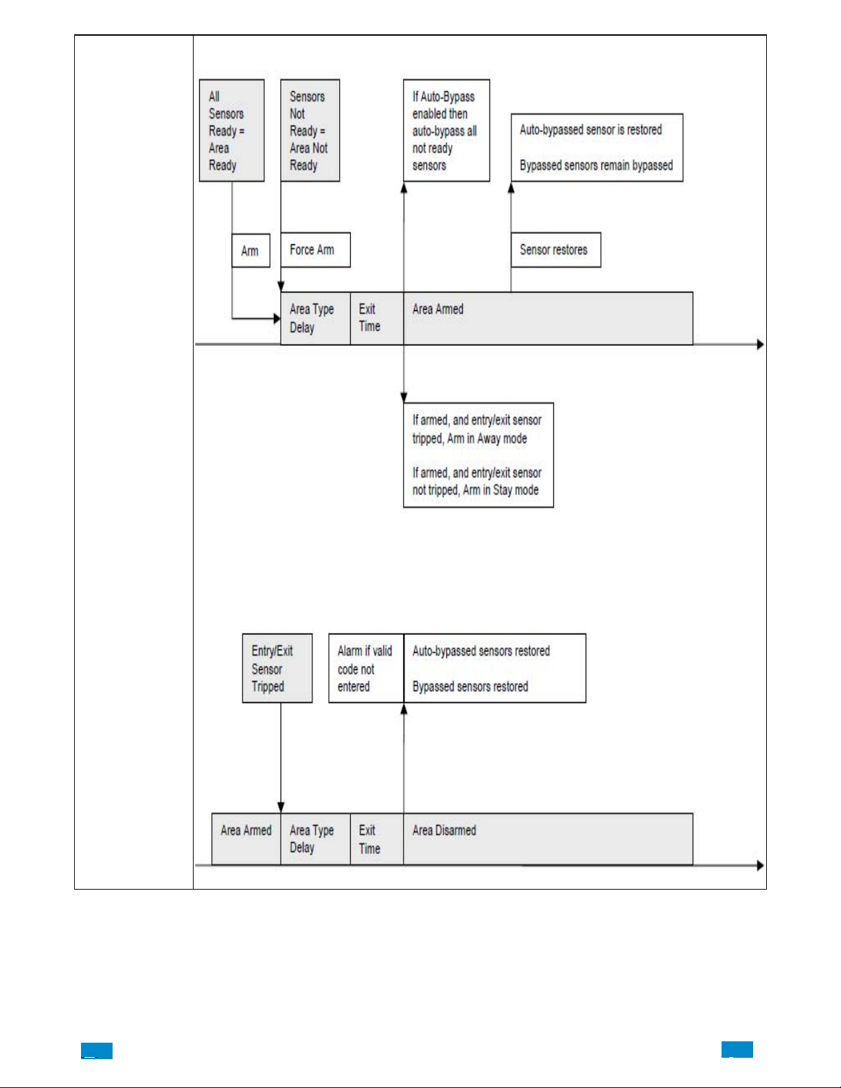
Areas Submenus
.C.
82
..
.I
Page 83
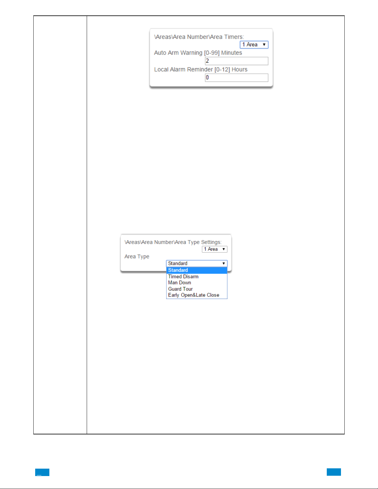
Areas Submenus
5 Area Timers
Auto Arm Warning
If the area type is Standard and Arm / Disarm is configured, this timer delays arming by the minutes entered.
If the area type is Timed Disarm, Man Down, or Guard Tour, this setting is a warning time given to a user once the
user’ s Disarm Time, Man Down Time, or Guard Tour Time has expired. During this warning time a user can cancel
the automatic re−arming and event report by entering their code, this will also restart the appropriate user timer. At
the end of the warning time, Côrwill re−arm the area and send the appropriate event (closing, man down, guard
tour fail).
If the area type is Early Open & Late Close, this timer sets the period after the start (opening) and after the end
(closing) of the area type schedule that the area can be disarmed or armed. Otherwise an early to open or late to
close report will be sent if enabled in user permissions. Fail to open and fail to close report will be sent if Arm−Disarm Reports is enabled in area options.
Valid values are from 0 to 99 minutes
Local Alarm Reminder
If set, the local alarm reminder is the period in minutes between 0 and 999 that may elapse between actioning a
local alarm and the local alarm reactivating if that sensor has remained open.
For example if a smoke detector is removed to change the battery the tamper will trip; if a user resets the alarm on
the Côr system but does not replace the smoke detector within the local alarm reminder time, then the fire alarm
tamper will retrigger.
6 Area T ype
.C
Standard
The area functions as normal.
Timed Disarm
Timed disarm is used when an authorized user can disarm an area for a predetermined period of time. At the end of
this disarm time the area will start the auto−arm process ensuring that the area is not accidentally left disarmed.
The following conditions must be true before a timed area disarm function will occur.
a. The area type must be set to Timed Disarm.
b. The area type schedule must be active.
c. The users active profile’s permission must have;
i. This area set in the permission’s timed disarm area group.
ii. The permission must be in schedule.
iii. The permission’s Area Type Override must NOT be set.
At the end of the user’s disarm time, the Area Type Delay will activate for the set period. At the end of the
Area Type Delay period the area will arm and start the Exit Delay and if configured, report a closing using
via the last user number to have time disarmed the area.
At anytime during the timed disarm period, authorized users with Area T ype Override set in their active
profile can cancel the disarm time period by arming or disarming the area
The user’s permission determines how long the area will be disarmed for.
83
..
.I
Page 84
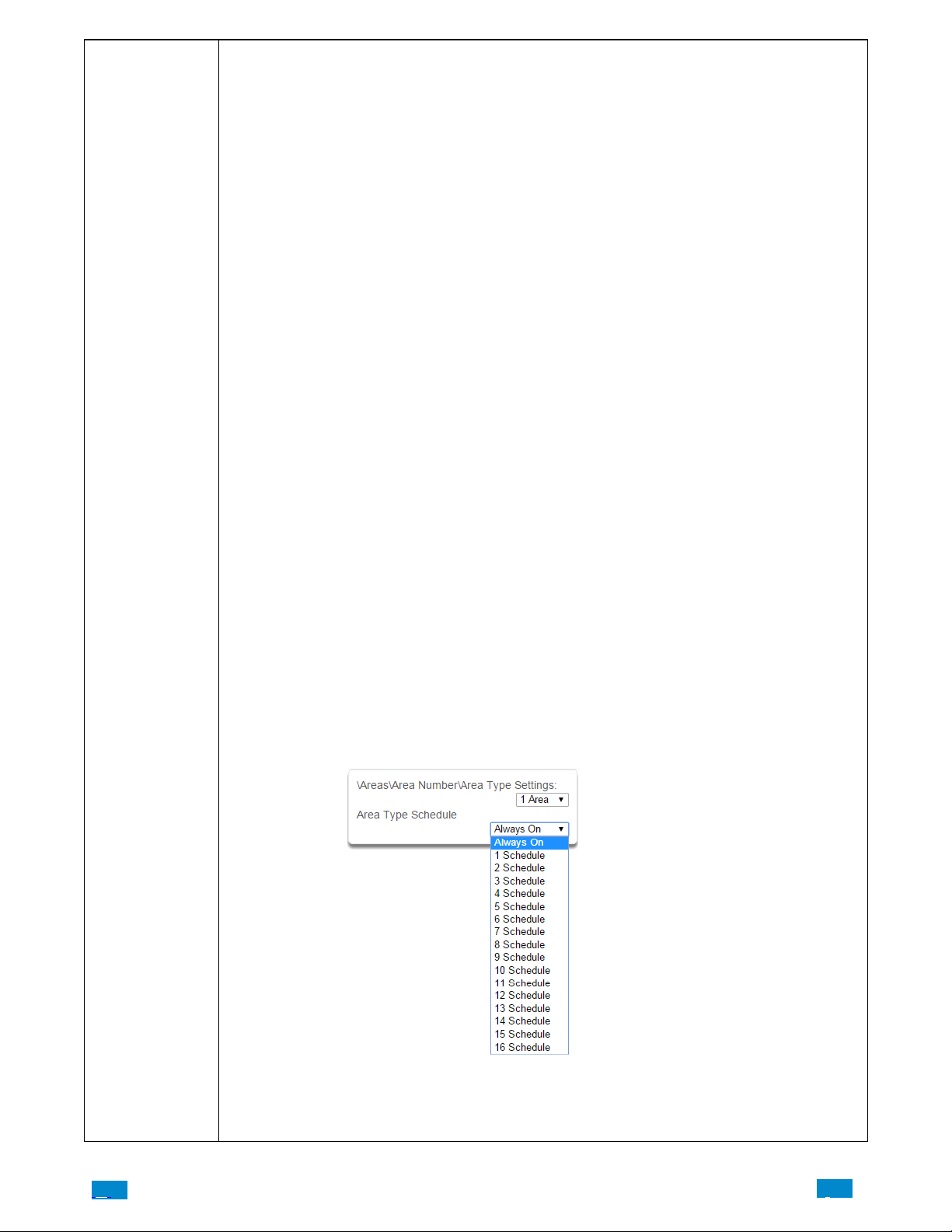
Areas Submenus
Man Down
Man down is used when an authorized user(s) is working in a hazardous area (or the like), and there is a requirement that the user(s) regularly “check−in” to notify others that the user(s) is safe. If the authorized user(s) fails to
perform this action the system can set an audible warning and send a report.
The following conditions must be true before man down function will occur.
a. The area type must be selected to man down.
b. The area type schedule must be active (after the start time and before the end time).
c. The uses active profile’s permission must have;
i. This area set in the permission’s man down group.
ii. The permission must be in schedule.
iii. The permission’s Area Type Override must NOT be set.
The man down timer is set in the user’s permission.
At the end of the user’s man down time, the Area Type Delay will activate for the set period. At the end of the Area
Type Delay period the area will arm and if configured, report a man down alarm. At anytime during the man down
period, authorized users with the Area T ype Override set in their active profile will cancel the man down time period by disarming or disarming the area.
Guard Tour
Guard tour is used when an authorized user(s) (such as a guard) is required to regularly “check−in” to notify others
that they have physically attended to a location(s) on the site. If the authorized user(s) fails to perform this action
the system can set an audible warning and report a “Guard T our Fail” event.
The following conditions must be true before guard tour function will occur.
a. The area type must be selected to guard tour.
b. The area type schedule must be active (after the start time and before the end time).
c. The uses active profile’s permission must have;
i. This area set in the permission’s guard tour group.
ii. The permission must be in schedule.
iii. The permission’s Area Type Override must NOT be set.
The guard tour time is set in the user’s permission.
At the end of the user’s guard tour time, the Area Type Delay will activate for the set period and keypad sounder
will be active. At the end of the Area T ype Delay period the area will arm and if configured, report a Guard Tour
Fail alarm. At anytime during the guard tour period, authorized users with the Area T ype Override set in their active profile will cancel the guard tour time period by disarming or disarming the area.
Early Open/Late Close
If the area type is Early Open & Late Close, the Area T ype Delay sets the period after the start (opening) and the
end (closing) of the area type schedule that the area must be either disarmed or armed.
For example, if the area type schedule is set between 8:00 AM (opening time) and 5:00 PM (closing time) and the
Area Type Delay is set to 15 minutes; then the area must be disarmed between 8:00 AM and 8:15 AM otherwise if
it is disarmed before 8:00 AM it is an early open, if it is disarmed after 8:15 AM it is late to open. Likewise the area
must be armed between 5:00 PM and 5:15 PM otherwise if it is armed before 5:00 PM it is an early close, if it is
armed after 5:15 PM it is late to close.
7 Area Type Schedule
.C.
One of 96 configurable schedules can be allocated to the area type schedule. The area type schedule determines the
schedule that the selected area type is active. Area types are not active when the schedule is not active. If an area
type schedule is disabled (always active) that area will always have the type characteristics programmed in Area
Type.
84
..
.I
Page 85
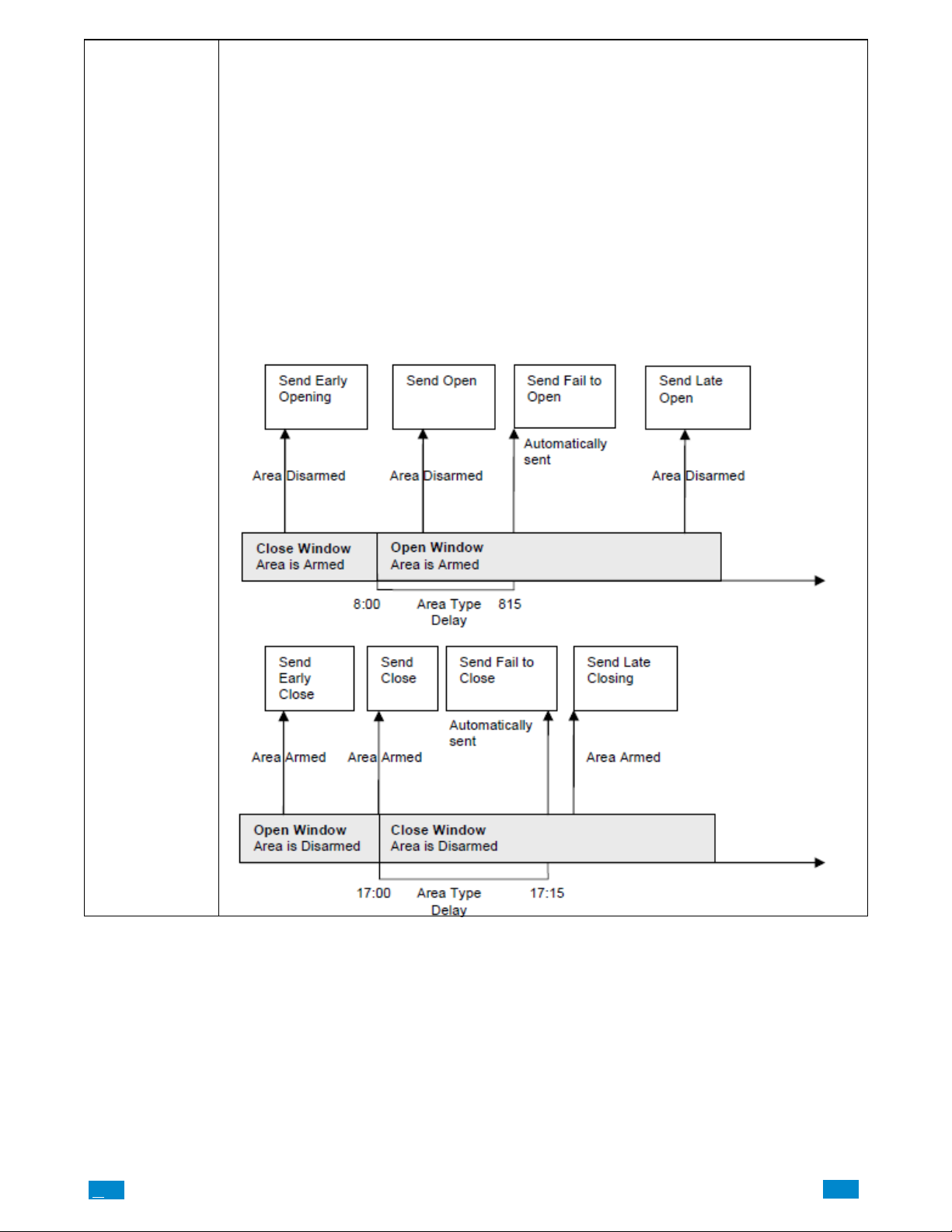
Areas Submenus
Area Type Delay
If the area type is Standard and Arm / Disarm is configured, this timer delays arming by the minutes entered.
If the area type is Timed Disarm, Man Down, or Guard Tour, this setting is a warning time given to a user once the
user’ s Disarm Time, Man Down Time, or Guard Tour Time has expired. During this warning time a user can cancel
the automatic re−arming and event report by entering their code, this will also restart the appropriate user timer. At
the end of the warning time the Côr will re−arm the area and send the appropriate event (closing, man down,
guard tour fail).
If the area type is Early Open & Late Close, this timer sets the period after the start (opening) and after the end
(closing) of the area type schedule that the area can be disarmed or armed. Otherwise an early to open or late to
close report will be sent if enabled in user permissions. Fail to open and fail to close report will be sent if Arm−Disarm Reports is enabled in area options.
Example
Area Type – Early Open & Late Close
Area T ype Schedule – 8:00 to 17:00
Area T ype Delay – 15 min
User Permissions – Options – Open/close report, Early open report, Late close report
Area Options – Arm−Disarm Reports
.C
85
..
.I
Page 86
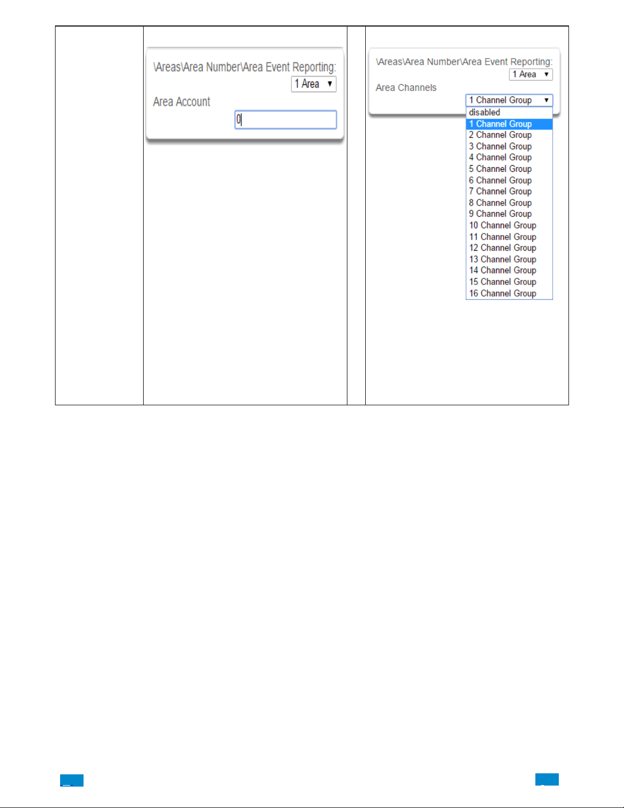
Areas Submenus
8 Area Event Reporting/Account 9 Area Event Reporting/Channels
If set, the area account code is a system unique 4 to
10 digit code (format dependent) used to associate
area related alarm reporting events to this area. If the
area account code is equal to the default of 0, the
channel account code will be used for this area’s
alarm reporting events. If the channel account code is
equal to the default of 0, the channel 1 account code
is used. If the channel 1 account code is 0 then the
account will be sent as 0
The channel group determines which communicator
channel(s) area events will be reported to. If the bit
corresponding to one of the 16 reporting channels is
set to on, area events will always be reported to this
channel. It is referred to as a primary reporting channel. If a report is unsuccessful to a particular primary
channel it will attempt that channel’s backup channels
if there are any.
.C.
86
..
.I
Page 87
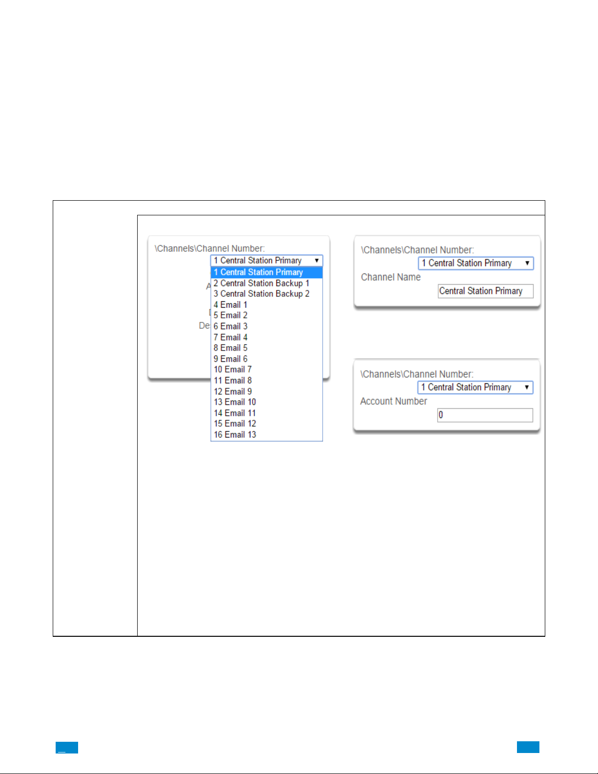
5.4 Advanced Programming, Channels
h
t
Select Channels from the drop down menu.
The Côr panel can support a total of 16 channels; each channel is a communication path for events to be sent from the Côr panel to a
selected destination.
Default configuration reserves Channels 1 – 3 for UltraSync format, Channels 4 – 16 are Email format.
Email is a “best−effort” system and there is no guarantee messages will be delivered by the network. When the network is busy, messages can
be dropped. Central control room monitoring is highly recommended as each event is acknowledged on receipt to ensure an appropriate
response can be made.
Installers have access to setup/modify all channels (1−16). Master Users have access to channels 7−16, which are used for email notifications.
Standard users do not have access to channels.
Channels Submenus
1 Channel Number 2 Channel Name
Areas Submenus
The Côr panel can support a total of 16 channels.
Each channel is identified by a unique channel number, which cannot be altered, and remains as the key
reference for each channel.
Channel 1 and channels 4−16 are configured as primary reporting paths by default. Channel 1 is disabled by default. Use as Backup as the Format selection has the effect of disabling reporting of a primary
channel. The Format must be selected to a value other
than Use as Backup to enable reporting. Channels
4−16 are configured as email reporting paths by default.
Channels 2 and 3 are configured as backup reporting
paths by default. Channel 2 is set to backup channel 1
and channel 3 is set to back up channel 2 by default.
Note that the primary channel must set the Next
Channel for back up reporting to function.
Custom names of the selected channel can be created
here
3 Account Number
This is the Account Number that will be reported wit
the event in email reports. When UltraConnect forma
is selected, this field will not be used.
.C
87
..
.I
Page 88
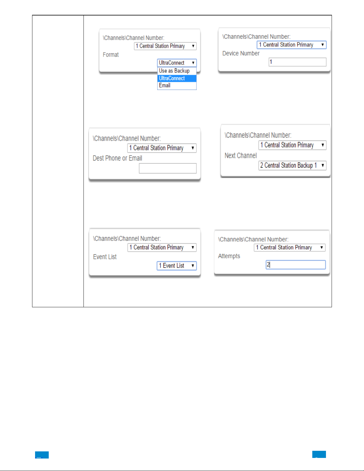
Areas Submenus
4 Format 5 Device Number
This is the communication format for the selected channel. When Use as Backup is selected, the backup path will
utilize the primary channel’s format. Note that the primary channel must set the Next Channel for back up reporting
to function.
6 Destination Phone/Email 7 Next Channel 1−16
The email address or mobile device name (push
notification) of the selected destination.
When enabling push notifications in the Côr
app, the device name will automatically be
set in destination phone or email.
8 Event List 1−16 9 Attempts
.C.
Select the pre−programmed list of events that will be
sent via this channel. The specific events in each
event list are programmed.
88
Enter the number of times Côrshould try to send
the events to the UltraSync server. After the number
of attempts has been exhausted the Côr panel will
try the Next Channel if specified.
..
.I
Page 89
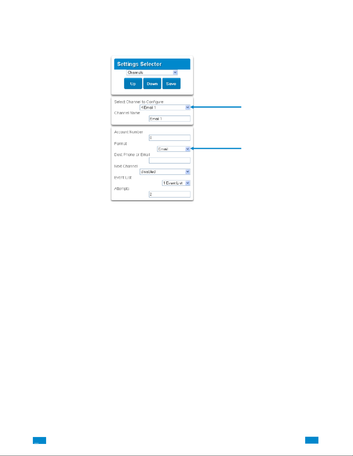
Configure Email Reporting
1. Login to Côr Web Server from your computer using the IP address.
2. Press Settings.
3. Select Channels in the drop down Menu.
4. Press Select Channel to Configure where the Format is already set to Email.
5. Enter an email address.
6. Select an Event List.
7. Enter a Channel Name for future reference.
8. Press Save.
Installer and Master User types can customize Event Listing for selective reporting.
.C
89
..
.I
Page 90
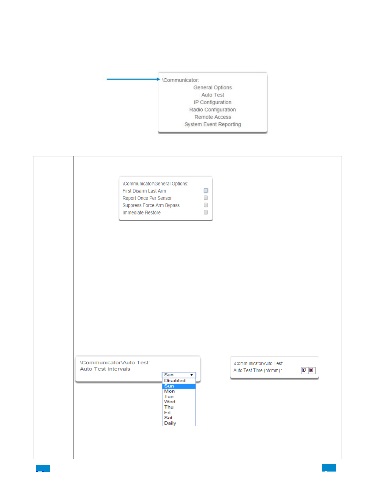
5.5 Advanced Programming, Communicator
Select Communicator from the drop down menu.
The Côr Communicator is a key component of the Côr System used in conjunction with the Channels feature to report events to a
monitoring company or third party. In this menu you can configure the settings for various methods of reporting.
Communicator Submenus
1. General Options
Communicator
Submenus
1. First Disarm Last Arm
If enabled, Côr will only send a closing report when the last area is armed.
NOTE: The last area to arm must have open/close reports enabled. Côr will only send an opening report when
the first area is disarmed.
This feature is used in place of Individual area Open and close. If you enable open and close in the area you will
get both individual open and close and System open close.
2. Report Once Per Sensor
If enabled, this will limit reporting to only once per sensor each time you arm or disarm an area. This stops the
control room or reporting destination to be flooded by multiple reports that the same sensor is being activated (for
example the intruder may be moving around and is being picked up by the sensor on that sensor).
3. Suppress Force Arm Bypass
If enabled, Côr does not send bypass reports when a sensor is forced armed. If not enabled, when a sensor is
forced armed and it remains in a state of creating an alarm, bypass reports are sent at the end of exit time. For example this would occur if it remains open at the end of the exit time, or due to change of sensor type caused by a
schedule. If forced armed sensors re−close during the armed period, bypass restores are sent.
4. Immediate Restore
If enabled, Côr will immediately send all restorals as the sensor reports the event.
If not enabled, Côr will send restoral events all at the same time when the marea is disarmed.
2 Auto Test/Intervals 3 Auto Test/Time
Enter the time at which the automatic test report should
be sent. This should be in 24−hour format. For example
18:00.
.C.
Set day of the week to send an automatic test report to
the system channel group .
(Communicator\System Event Reporting\System Channels). You may also set auto−test to Daily
90
..
.I
Page 91
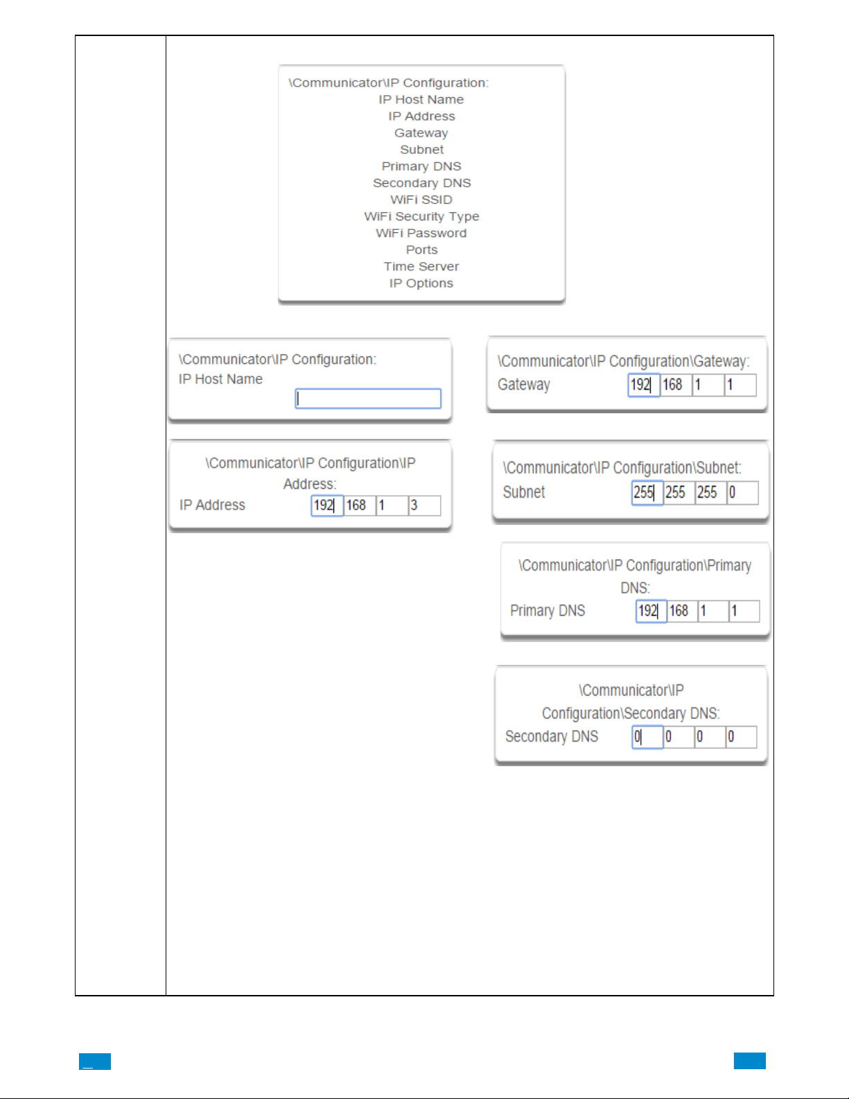
r
4 IP Configuration
e
5−6 IP Config Detail 7−10 IP Config Detail
Communicato
Submenus
Host Name
This is a text label assigned to the Côr communicator
so you do not have to remember the IP Address.
NOTE: This only works on local LAN and with Microsoft Windows PC, or an Apple device with the local
extension. Does not work remotely over the internet.
IP Address
The IP address assigned to the Côr communicator
to enable it to connect on to the local LAN. This
will allow you access to the embedded web server
from a web−enabled device to program and view th
status of the system. It is also used for alarm reporting.
Gateway
If required, the IP address of the router which is needed
when remote IP communications are used .
Subnet
The subnet mask for the network.
For example, 255.255.255.0 is the network mask for
192.168.1.0/24.
Primary DNS
The IP address of the Primary Domain Name Server.
The DNS is used to translate host names for time servers
and UltraSync servers
Secondary DNS
The IP address of the Secondary Domain Name Server,
used if the Primary DNS is not available.
.C
91
..
.I
Page 92
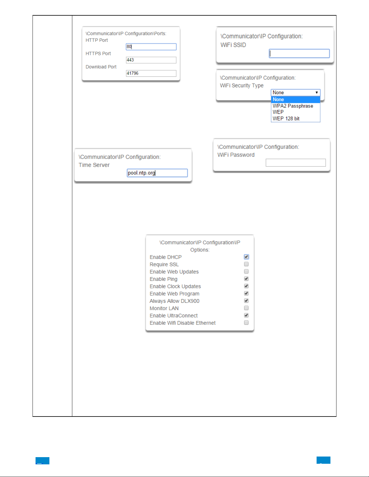
r
11 Ports 12−14 IP Config Detail
The ports that the computer needs to communicate with
the Côr system.
Defaults:
HTTP Port = 80
HTTPS Port = 443
Download Port = 41796
15 Time Server
Communicato
Submenus
Enter the URL or IP address of a time server to
allow Côr to automatically update and
synchronise its clock without user intervention.
The default is pool.ntp.org
16 IP Options
1. Enable DHCP
Allow the Côr panel to be automatically assigned an IP address by the network.
2. Require SSL
Feature no longer supported. Leave unchecked.
3. Enable Web Updates − RESER VED
Allows the Côr panel to update the web pages via a network. Go to Hostname/mpfsupload to update
the web pages served by Côr. Does not update firmware.
4. Enable Ping
Allow the Côr panel to respond to the PING command
5. Enable Clock Updates
Allow the Côr internal clock to synchronise with the internet time server specified .
.C.
92
..
.I
Page 93
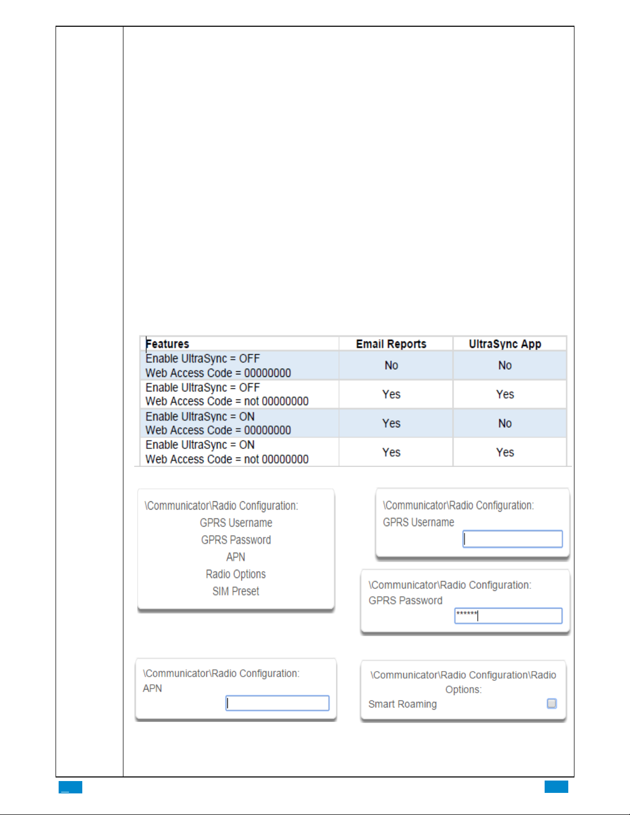
6. Enable Web Program
Enabling this option will cause the Côr W eb Server and app to always display Installer menus regardless of if
the panel is in program mode or not.
Disabling this option will hide the Installer menus on the Côr Web Server and app unless program mode is active. This provides greater security by keeping web programming disabled unless a user on site with physical
access to the keypad enters program mode with a valid PIN code.
Côr panel will be in program mode if a user gains access to menu 5, 8, or 9. The Côr app requires the Web
Access Code to get access to the panel.
7. Always Allow DLX900
Enabling this option will allow DLX900 to connect at any time if the correct Download Access Code is
provided.
Disabling this option provides greater security by only allowing DLX900 to connect when program mode is active. This allows the system to have DL900 access disabled until a user on site with physical access to the keypad
enters program mode with a valid PIN code.
Côr will be in program mode if a user gains authorised access to menu 5, 8, or 9 on the keypad
8. Monitor LAN
When the Monitor LAN option is enabled the panel will monitor the Ethernet port for a valid Ethernet cable. If
the Ethernet cable is disconnected while this option is enabled, and the panel is unable to communicate, it will log
a Fail To Communicate event.
9. Enable UltraConnect (UltraSync)
This is an automatic feature of Côr. It is recommended you leave this setting on.
Enable this option to allow Côr to send email reports via the UltraSync servers. This is independent of the W eb
Access Passcode which when set to 00000000 will prevent the Côr app from connecting.
If any channel is set to Email format reporting, then Côr will override ignore this setting and allow email reporting via UltraSync cloud servers.
If you wish to prevent connections to the Côrcloud servers, then uncheck this option and do not use the UltraSync reporting format.
Communicator
Submenus
17 Radio Configuration 18 GPRS Username/Password
19 APN 20 Radio Options
.C
Access Point Name (APN) for the settings to set up a
connection to the gateway between the cellular network
and the public Internet.
93
..
.I
Page 94
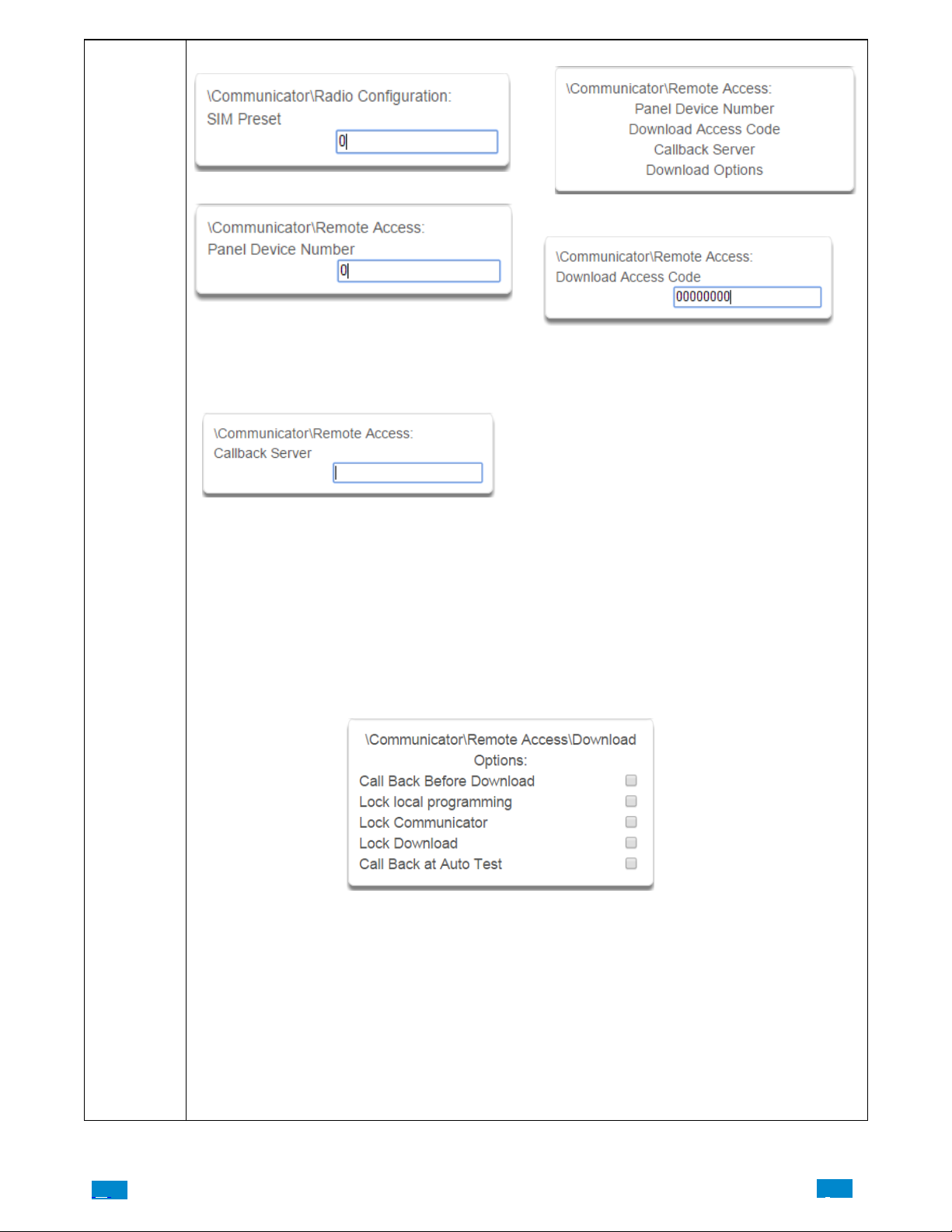
21 SIM Preset 22 Remote Access
23 Panel Device Number
24 Download Access Code
Communicator
Submenus
A number from 0 to 4,294,967,295 that must be entered
in to the desktop software for remote access to take
place.
25 Callback Server
If an IP address or host name is programmed into this
feature, and “Call Back Before Download Session” is
enabled, the Côr will disconnect for approximately 10
seconds and then connect to this IP address. This should
be the IP address of the computer where DLX900 is
installed, not the IP address of the Côr panel.
IMPORTANT: the call back IP address should always
be reviewed for accuracy before disconnecting.
26 Download Options
A variable length code for the computer user. This code
gives the software complete authority over all menus
including those that are locked. For convenience
DLX900 will also try installer and 9−7− 1−3 to allow a
connection for first time set up if the Download Access
Code does not work This is why changing the default
code is important
The default Download Access Passcode of 00000000
prevents remote access
Changing this code may lock out your control room
monitoring service and prevent you from maintaining
your system. It is advised you contact your control room
before changing this code.
Users must have access to the Communicator menu in
order to change this setting. This can be programmed in
Menus, and assigning the “Advanced” menu.
.C.
1. Call Back Before Download
If a download is requested the Côrwill hang up and make a call to the Call Back Number. This is to increase the
security of remote access.
2. Lock local Programming
Prevent changes to the Côrsystem via a keypad, all changes MUST be made using the remote access software.
3. Lock Communicator
Local programming locks all programming unless accessed with the Download Access code. Lock communicator
locks local programming of communicator features unless accessed by the Download Access Code.
4. Lock Download
Prevents the programming of the Remote Access Menu without using the Download Access PIN.
5. Call Back at Auto Test
When an auto test is initiated, perform a call back to the number specified.
94
..
.I
Page 95
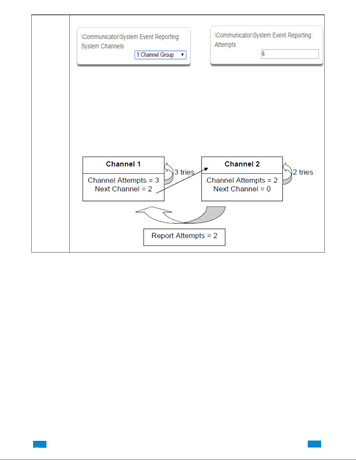
27 Event Reporting / Channels 28 Event Reporting / Attempts
Communicator
Submenus
Enter the Channel Group that the Côr will send system
events to.
Example
If Channel 1 is the primary, and Channel 2 is the backup for Channel 1, then when both channels fail it will go back to
Channel 1. This setting controls how many times Côr cycles back to Channel 1 before it gives up.
The Channel Attempts setting controls how many times Côrstays on the channel before switching to the backup.
Always check the max. number of attempts on all channels to avoid unexpectedly high communication charges.
In the diagram below, Côr will try Channel 1 3 times, switch to Channel 2 and try 2 times, then go back to Channel 1.
This sequence is repeated 2 times in total. In total there will be 10 attempts.
This is the number of times the Côr will sequence
back to the primary channel if the backup channels all
fail. This applies to ALL communication attempts including sensor and area events.
.C
95
..
.I
Page 96
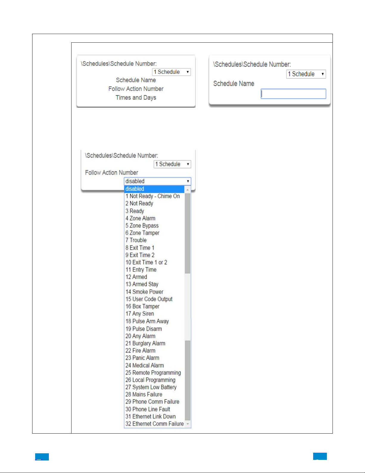
5.6 Advanced Programming, Schedules
Select Schedules from the drop down menu.
1 Schedule Number 2 Schedule Name
Schedules Submenus
Schedules
Submenus
The Côr panel can support a total of 96 schedules.
Each schedule is identified by a unique schedule number, which cannot be altered, and remains as the key
reference for each schedule.
3 Follow Action Number
Each schedule can be configured with a custom 32 character name. The area name is displayed wherever a
schedule is referenced on the Côrsystem.
If an action number is specified, then the schedule becomes enabled when the action is true. When the action
becomes false, then the schedule becomes disabled
Schedules can be used to control various parts of the
system such as when a user’s permissions are applied.
The “Follow Action Number” option allows you to use
actions to control schedules.
The result is actions can control when permissions are
applied, when area types are applied, sensor behaviors,
when arm−disarm can occur, and when scenes play .
This allows you to create conditional schedules that only
become active when certain conditions are met. For example you could create a user that only becomes active
(because of the linked schedule) under certain conditions
like a fire alarm.
.C.
96
..
.I
Page 97
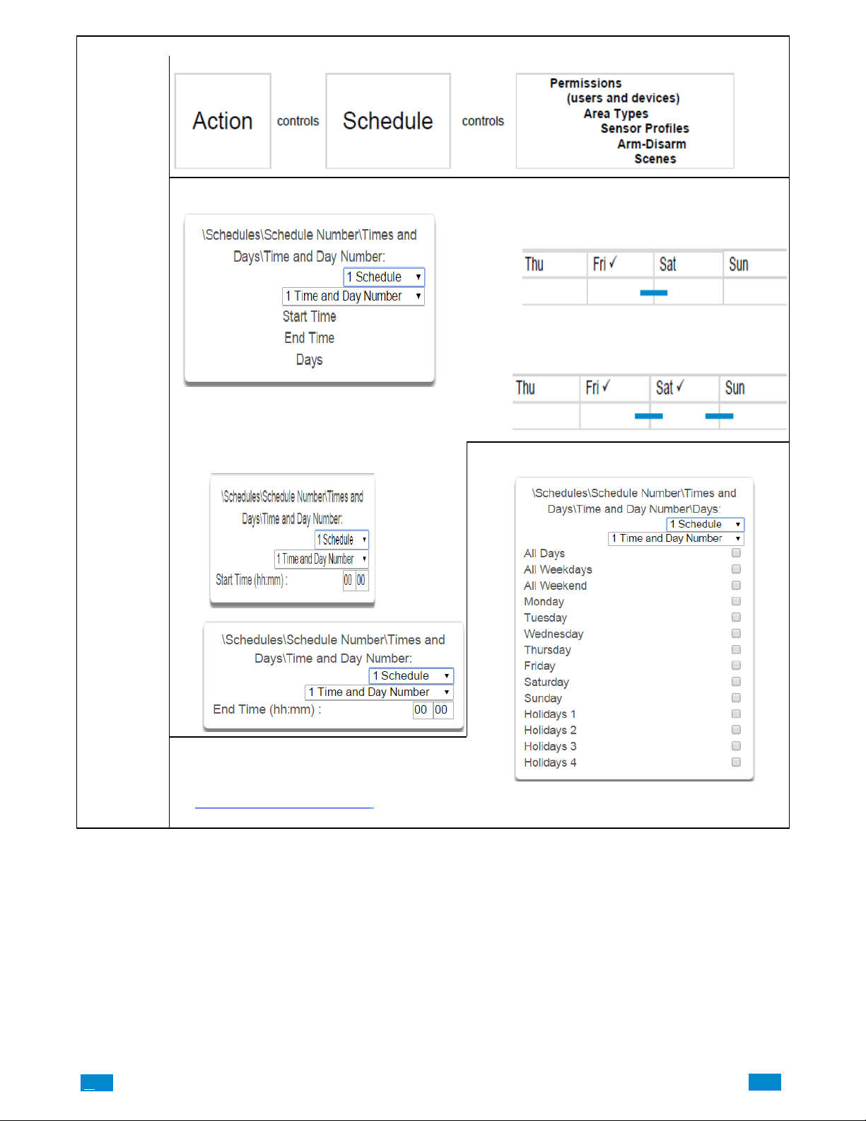
Follow Action
-
4 Times and Days Côr handles schedules that span midnight automatical
ly. For example, if a schedule is to cover Fri 8:00pm to
Sat 6:00am, only check Friday and Côr will automatically manage the time after midnight.
If you check Friday and Saturday, the schedule will cover Fri 8:00pm – Sat 6:00am and Sat 8:00pm – Sun
6:00am.
Schedules
Submenus
Up to 16 sets of time and days can be specified here.
5 Start Time / End Time 6 Days / Holidays
Note: Holidays 1−4: If checked, it means the item assigned this schedule will NOT have access during the
specified holiday dates.
See Advanced Programming, Holidays
dates.
to program these
.C
97
..
.I
Page 98
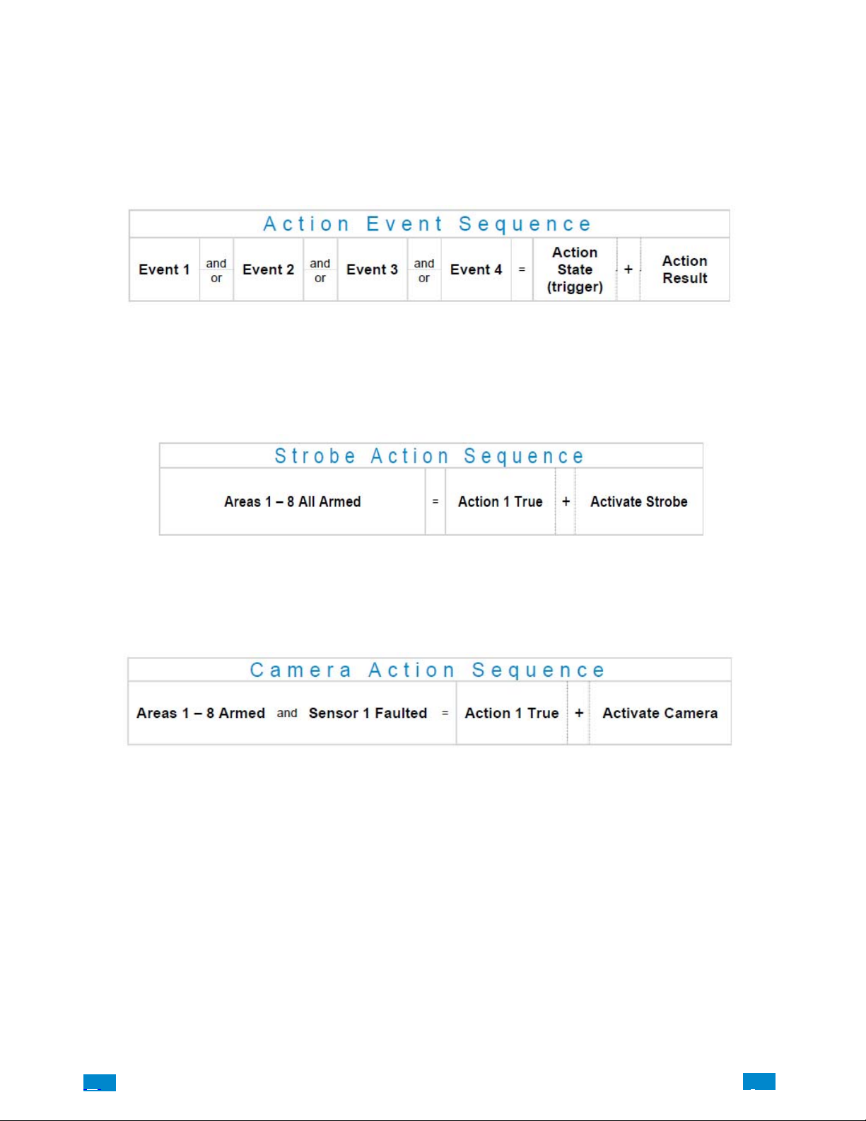
5.7 Advanced Programming, Actions
The Côr panel features powerful automation control which can interact with different parts of the system. It can perform functions based on
the status of one or more system conditions.
These features are considered advanced programming and should only be changed by an installer with a thorough understanding of the
features.
Each action has an on and off state. The state is controlled by up to 4 conditions called Action Events, each of which can have a range of
items:
When all 4 Action Events are met, then the Action State (trigger) will be set. The Action State can be monitored by the main Côr Panel,
Schedules, Devices with outputs, and Scenes to activate/deactivate.
For example, a strobe connected to Output 1 can be programmed to follow Areas 1 – 8 being armed.
Each Action can also directly control selected parts of your Côr when all 4 Action Events are met. This is called the Action Result. Its
behavior also follows the Action State.
For example, when all areas are armed and there is activity on sensor 1, activate a camera recording.
Select Actions from the drop down menu.
.C.
98
..
.I
Page 99
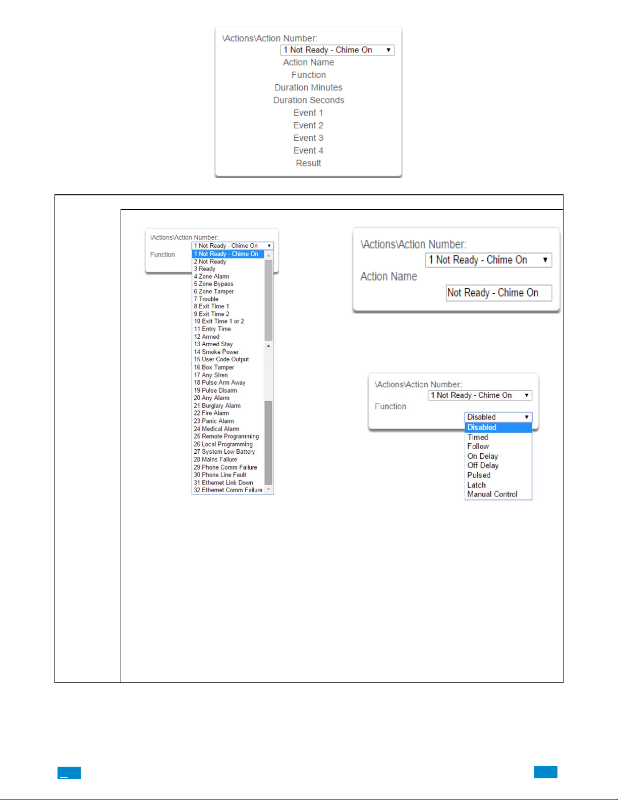
Actions
Submenus
Actions Submenus
1 Action Number 2 Action Name
Each Action can be configured with a custom 32
character name. The name is displayed wherever
an Action is referenced on the Côr system.
3 Function
.C
The Côr panel can support a total of 32 Actions.
Each Action is identified by a unique number,
which cannot be altered, and remains as the key
reference for each Action.
Note: All 32 actions are pre-programmed with the
specified trigger. To create a new action, you need
to modify one of these actions.
99
• Timed – The action state turns on for the time
specified.
• Follow (Recommended) – The action state turns
on once the Event conditions have been satisfied,
then off once the Event conditions are not true.
• On Delay – The action state becomes on after
the programmed time period unless logic result is
no longer active.
• Off Delay – Follows the result of the logic equa
tion, but remains active for the time programmed
after the logic result is no longer active.
• On Pulse – Action state turns on for the pro
grammed time or the active period of the logic re
sult, whichever is the SHORTEST.
• Latch – The action state stays on once the Event
conditions have been satisfied
..
.I
Page 100
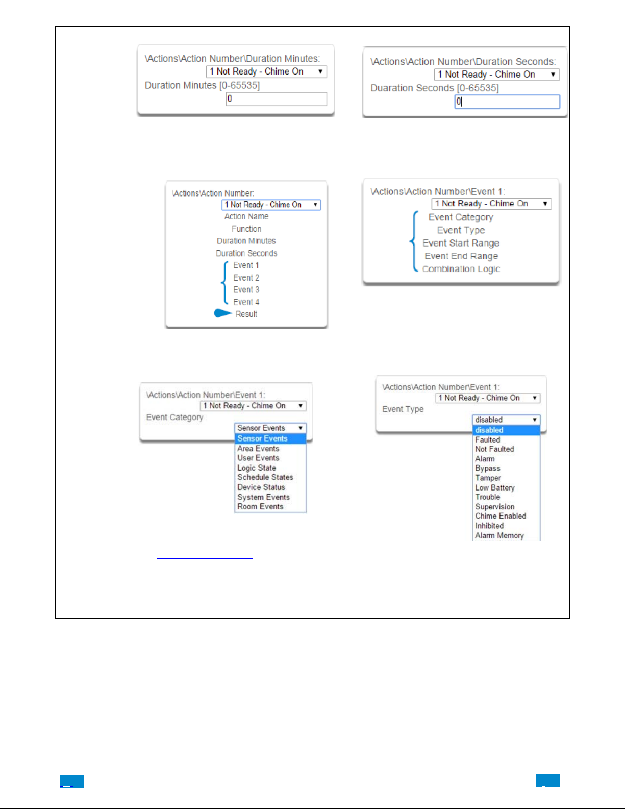
4 Duration: Minutes 5 Duration: Seconds
Actions
Submenus
Where the Function requires duration, this deter
mines, in minutes, how long the action should stay
on.
6 Event(s) 1-4 and Results 7 Event Attributes
8 Event Category 9 Event Type
Where the Function requires duration, this deter
mines, in seconds, how long the action should stay
on.
.C.
Select the category of the first event. This will deter
mine what events you can select in Event Type.
See the Action Events Category and Action Event
types table in section A.10 for reference.
100
Select the event that you want the Action to moni
tor.
See the Action Events Category and Action Event
Types table in section A.10 for reference.
..
.I
 Loading...