

Page 1

CONTENT
Ⅰ Introduction ……………………………………… 2
1. Introduction ………………………………… 2
2. Features ……………………………………… 2
Ⅱ Connection ………………………………………… 2
1. Rear layout …… …………………………… 2
2. Remote control connector……………………3
3. System connection …………………………4
Ⅲ Front Panel Button and Functions …………………… 4
1. Front Panel layout ……………………………… 4
2. MENU …………………………………………… 4
3. PLAY …………………………………………… 4
4. QUAD【FREEZE】 …………………………………… 5
5. ENETR【AUTO】 ……………………………………5
6. “1”,“2”,“3”,“4” … ……………………… 5
Ⅳ MENU SETTING ………………………………………… 6
1. SYSTEM SET …………………………………… 7
2. CAMERA SET …………………………………… 8
3. MOTION SET …………………………………… 9
4. CONFIRM RESET ……… ………………………… 10
Ⅴ Function Operation …………………………………… 10
1. LOSS Alarm ………………………………… 10
2. MOTION Alarm ……………………………………11
3. Alarm confirm ……………………………… 11
4. Playback ………………………………………11
5. Picture Freeze ………………………………12
6. Auto Sequence ……………………… ……… 12
- 1 -
Page 2
Ⅰ Introduction
1. Introduction:
Thank you for using the product, 4 Channel Digital Multiplexer. Which is a new product
with powerful functions. In this operation manual will introduce this product’s special
feature, installation and control method, try to help you understand the product in deep and
quickly.
SPECIFICATIONS AND INFORMATION CONTAINED IN THIS MANUAL ARE
FURNISHED FOR INFORMATIONAL USE ONLY, AND ARE SUJECT TO
CHANGE A T ANY TIME WITHOUT NOTICE.
2. Features:
1) Screen display,date, time, alarm event, video loss and Camera title (10 characters).
2) Loss alarm
3) Live picture freeze
4) Camera title setting
5) Auto dwell
6) Camera picture quality setting
7) 4×Zoom picture playback
8) Motion detection alarm and programmable motion for each channel
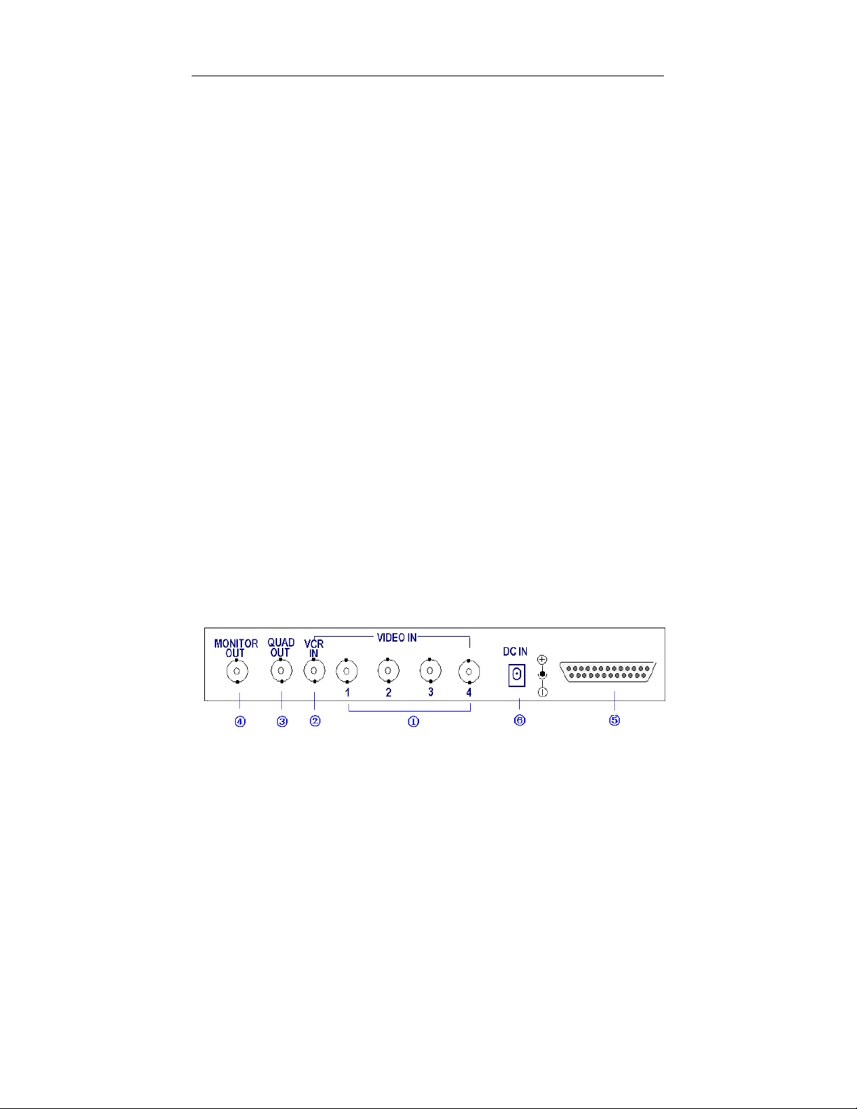
1. Rear layout:
ⅡConnection
- 2 -
Page 3

①- Video signal input. Four video input connectors, may connect four
cameras or other standard video signal.
②- VCR connector. Connect VCR Output, playback picture and display live
picture.
③- Quad out. Connect VCR input,recording the live picture。
④- Monitor out. Connect Monitor video in, display camera live picture。
⑤- Remote control and alarming port: DB25 port which supports
RS232/RS485 communication and alarm input/output.
⑥- DC Adapter input, (DC12V/1.2A)
2. Remote control and alarming port
DB25 port
1.Blank 2.TXD 3.RXD 4.Blank 5.GND 6.Blank 7.ALARM
CLOSE 8. ALARM COM 9. ALARM OPEN 10. Blank 11.A
12. B 13. Blank 14. ALARM IN1 15. ALARM IN2 16. ALARM
IN3 17. ALARM IN4 18----23. Blank 24.GND 25.VCC
Serial data are of remote transmitting function, which makes it is
possible to control the multiplexer by a PC or ASCLL terminator in
a long distance. The front panel buttons of the multiplexer are
corresponding to particular commands. As the serial data can realize
the same controlling function as the front panel buttons, any
command that is ava ilable can be realized in a long distance.
The communication protocols are contained in the appendix.
- 3 -
Page 4
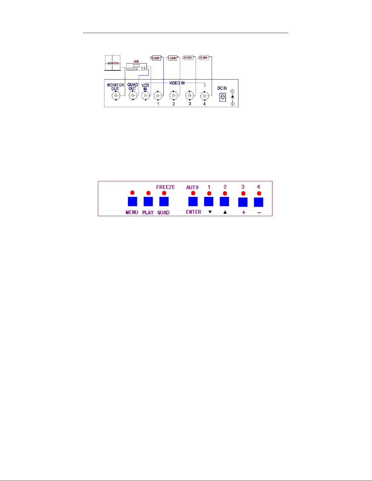
3. System connection:
Ⅲ Front Panel buttons and function
1. Front panel layout:
2. MENU
(1) When in the live or playback, keep pressing MENU key and enter the menu. The
menu indicator lamp is on.
(2) When operating in the menu, press the key to go back to upper stage menu.
3. PLAY
(1) When in the live picture, press this key, the play indicator lamp is on, the main
monitor displays “PLAY” on the top of screen, Quad processor begins playback
picture, Press the“1”、“2”、“3”、“4” key, you will see each channel playback
picture。
(2) When in the live picture, keep pressing PLAY key, the PLAY indicator lamp
flash, you will see the VCR quad picture and the screen display “VCR IN” on
- 4 -
Page 5

the screen. but no other characters display on screen.
(3) In the “MENU SET” item, the PLAY key meaning“←” key。
4 QUAD【FREEZE】:
(1) When in the live picture(not in MENU SETTING or AUTO DWELL
state),press“QUAD” key,4 channel screen will display.
(2) Each channel picture freeze:when in 4 channel picture mode, press the
“QUAD” key,“FREEZE” indicator lamp will be on, the picture will be at each
channel picture freeze state, press“1”、“2”、“3”、“4”key, the corresponding
“1”、“2”、“3”、“4” picture will freeze. The “FREEZE” character on the screen
will flash. Press the key again or the freeze time is over, the picture will resume.
(3) In the “MENU SET” item, the key“QUAD” meaning“←”key。
5 ENETR【AUTO】
(1) In the MENU SET mode, press “ENTER” key, select desired menu item.
(2) When in other mode but not menu mode, press“AUTO” key, the AUTO
indicator light on, the screen will be on AUTO DWELL mode, press the
“AUTO” key again, the indicator light will be off, Auto dwell will be
canceled.
6 “1”,“2”,“3”,“4”(“▲”,“▼”,“+”,“—”)KEY
(1) When in 4-screen splitter display mode, the number key can display opposite
channel picture or freeze opposite channel picture.
(2) When in menu setting mode, the number key can move cursor to select desired
item or to change the particular values setting.
- 5 -
Page 6
Ⅳ、MENU SETUP
When choose among the menu setting and other settings, press (↓)and (↑) to move the
cursor among selectable items up and down, press (←) and (→) to move the cursor
horizontally, press (+)and (-) to change the particular values setting. Press [
to enter the Sub-Menu.
Press ENTER key to enter the Sub-Menu after choosing one item in the menu.。After or
during the process of settings, press “EXIT” to save setting parameters and go back to upper
stage menu
before entering the main menu.
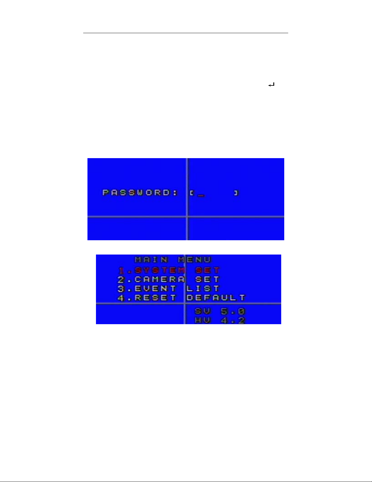
When in the live or playback mode, Press the “MENU” key for a long time to enter menu
mode, the screen display as follows:
,If already in the main menu state, press “EXIT” to go back to the splitter state
] key
Press the passw ord:1111,into the Main Menu.
- 6 -
Page 7

In the lower right of the Main Menu, the software and hardware version of this processor
will display.
System will exit and go back the splitter state before entering the menu after three
minutes without any operation
Th e fa cto ry def aul t pa ssw ord is 1111 . To l oad th e fa cto ry d efa ul t pa ssw ord , p res s ke y
“1” and “2” simultaneously and restart the machine.
SYSTEM SET In Main Menu, choose SYSTEM SET Menu then Press “ENTER”
key to enter.
Press the (↓),(↑),(←),(→)key for down, up, left and right and
Press (+)/(-) key to change particular setting.
TIME:SYSTEM DATE,YYYY/MM/DD(Y/M/D); SYSTEM
TIME,HH/MM/SS(H/M/S)。
FORMAT:
format;EURO:European format]。
LIVE TIME DISP:
TOP_LEFT:Upper left TOP_RIGHT:Upper right NON:
DATE FORMAT [ASIA,Asian format;U.S.:American
Live time display position [TOP:Middle up;
- 7 -
。
Page 8

No display]。
BORDER DISP:
OFF]。
BACK COLOR:
VFILTER:
BUZZER:
ALARM TIME:Alarm output lasting time。[003―255] Sec
FREEZE TIME:Freeze time [000―255] Sec, 000 sec means
illimitable time freeze。
Buzzer alarm。[ON,OFF]。
Border color [GRAY ,WHITE, BLACK ,
Background color [Blue, Black]。
Video filter type [ON, Soft; OFF, Clear]。
FORMAT:Format。[PAL,NTSC],The default format is NTSC。
CAMERA SET In the Main Menu, choose CAMERA SET Menu then Press ENTER
key to enter.
Press the (↓),(↑),(←),(→)key for down, up, left and right and Press
(+)/(-) key to change particular setting.
CAM:
Camera number from 1 – 4.
TITLE DISPLAY:
Close.
- 8 -
Camera title display switch. Y for open, N for
Page 9

CAMERA TITLE:Camera title compilation,random combination
of 10 characters includes Alphabet, Numerical and Symbol
AUTO TIME:Auto dwell time [0―99]Sec
PICTURE QUALITY :Camera picture quality setting。
BRIGHT:[0―255] 。
CONTRA:[0―255]。
SHROMA:[0―255]。
SHARP :[0―255]。
DEFAULT: camera default picture quality setting.
MOTION SET Choose “ MOTION SET ” in the Main Menu, then press ENTER key
to enter the Sub-Menu “ MOTION SET”.
Press the (↓),(↑),(←),(→)key for down, up, left and right and Press
(+)/(-) key to change particular setting.
CAMERA: Camera number [CMA1―CAM4]
SENSITIVITY: Sensitivity level: 00-99, the lower means the
higher sensitivity. (Note:Absolute motion detection threshold)
MD/NUM: Alarm number。00―99,the lower means the more
chances to alarm
(Note:Threshold of window number for generating motion alarm)
REFRESH: Refresh interval。00―99,(01 = lowest; 10 = highest)
( Refreshing interval of reference image in Auto refresh mode)
- 9 -
Page 10

MOTION SWITCH:motion alarm switch [ON-open,OFF-close]。
DETECT TIME:Motion alarm detect time.
When setting, the moving area will become burgundy. Thus you can
set the above three motion alarm parameters.
Press ENTER key until the red cube occur, the upper left Conner of monitor screen will
occur a red color cursor, move this cursor to green color areas by using(↓),(↑)(←),(→)key
for down, up, left and right and Press (+)/(-) key to choose or delete green color area. Then
press ENTER to save the particular setting changes and exit
CONFIRM RESET To change the machine to default setting, please choose “YES”
and then, press “ENTER” key to confirm. To cancel changing
the default setting, pleas choose “NO”, then press “ ENTER”.
Ⅴ OPERATION
LOSS ALARM When the camera signal is lost, it will switch to 4 channels splitter
picture. Buzzer alarm (programmable) and alarm output will occur and
the character “LOSS” and indicator lamp flash. Buzzer alarm will stop
when press any key or camera signal resume.
- 10 -
Page 11

MOTION ALARM If motion detection is open, the picture on screen is change, buzzer
alarm and alarm output will occur and the indicator lamp and
“MOTION” character flash, the buzzer alarm will stop if press
any function button or alarm time is over.
CONFIRM ALARM There are two confirm-alarm methods, auto and manual. When
in the Menu and playback mode, only can wait for system’s auto
confirmation (alarm displayed character and indicator lamp must be
confirmed manually before the message disappears). In any
circumstance, the system will confirm automatically if no
key-pushing operation in alarm time.
⑴Buzzer alarm confirm: Only when confirm alarm is achievable,
press any key to stop buzzer alarm. If there is continuous alarm,
buzzer alarm will not occur. Only after alarm time (start from the last
time if continuous alarm occurs), when alarm reoccurs, the buzzer
alarm will occur (Set alarm time in the “ALARM TIME “ of
SYSTEM SET)
⑵Alarm displayed character confirm: During the process of alarm ,
press the key to delete the displayed character, and press any of “1”、
“2”、“3” “4” key, alarm displayed character will be deleted in the
current channel and the indicator lamp will be off. If continuous alarm
occurs, press the corresponding digit keys to delete the displayed
character and the indicator lamp will be off. But it will resume after a
period.
PLAYBACK When in the live state, and not in the Menu、AUTO setting, press
“PLAY(VCR)”key, the indicator lamp is on ,the character “PLAY”
appears in the main monitor and the processor begins to play. If no
playback signal input, “NO PLAY VIDEO” will appear in the monitor.
- 11 -
Page 12

When in the playback mode, press “PLAY”key, the indicator lamp is
off, the processor returns to live state.
PICTURE FREEZE when in 4 channel picture mode, press the “QUAD” key,
“FREEZE” indicator lamp will be on, the picture will be at each
channel picture freeze state, press“1”、“2”、“3”、“4”key, will freeze
the corresponding “1” “2” “3” “4” camera picture. The character
“FREEZE” on screen will flash. And press any number key to release
screen freeze state.
AUTO DWELL when in the live state, press “AUTO” key, the indicator lamp is on,
the screen will be in auto dwell state of big picture, the indicator lamp
of the corresponding picture is on.
It dwells according to the scheduled time automatically. You can set
the dwell time of every picture in the “AUTO TIME” of “CAMERA
SET”. Press “AUTO” key again to cancel the auto dwell state.
Appendix :communication protocols
1) PTC 1 (ROBERT) (fixed character string length)
Serial port setting: BAUD,n,8,1(BAUD =1200,2400,4800,9600,19200)
Commands
(CHAR)
/AF 0x2F 0x41 0x46 MENU/EXIT FUNC+FULL
/SQ 0x2F 0x53 0x51 AUTO/ENTER
/TP 0x2F 0x54 0x50 VCR/LIVE
/22 0x2F 0x32 0x32 2X2
/01 0x2F 0x50 0x50 Cameras1/ up arrow
/02 0x2F 0x33 0x33 Cameras2/ down arrow
/03 0x2F 0x34 0x34 Ca meras3/ add
Sexadecimal
numbers
Function Note(keyboard)
- 12 -
Page 13

/04 0x2F 0x4C 0x56 Cameras4/ dec
2) PTC 2 (ROBERT_EXT) (fixed character string length)
Serial port setting: BAUD,n,8,1(BAUD =1200,2400,4800,9600,19200)
Transmitted
Transmitted Value Note
serial
number
Byte0 0x03 Fixed bits
Byte1 0xaa Recognizable characters of the
multiplexer
Byte2 0x01 Fixed bits
Byte3 Device id Address of the multiplexer
Byte4~6 见 PTC 1 (ROBERT) The command is the same as PTC
(ROBERT)
3) PTC 3
Serial port setting: BAUD,n,8,1(BAUD =1200,2400,4800,9600,19200)
Sent off by PC (variable length)
buf_232[
0]
0xa0 counter 0x00~ff functi
buf_232[
1]
buf_232[
2]
buf_2
32[3]
buf_2
32[4]
buf_2
32[n]
buf_23
2[n+1]
on
Start sign Data
length
(n+1)
Address
of
device
Funct
ional
codes
check_s
um
MU4
//function 0x01_key_function,0x02_ write eeprom, 0x03_ read eeprom,
0x04_ disp mode change, 0x05_restart, 0x06_general message query
eeprom command: buf_232[4]__change the character size,the
starting position of buf_232[5]__eeprom is high ,the starting position of
- 13 -
Page 14

buf_232[6]__eeprom is low,buf_232[7]…..__change the value
functional code(buf_232[3]):
0x01 key_function command:buf_232[4][5][6] is the same as PTC 1
(ROBERT)
Function code(buf_232[3]):
0x02 write eeprom
Sent out by PC(the character string length is variable)
Byte0 Byte1 Byte2 Byt
e3
Byte4 B
Byte6 Byten Byte[
yt
e5
0xa0 counter 0x00~ff 0x02 length hi
g
low
addr
Data n
h
ad
dr
Start
sign
Data
length
(n+
1)
Address
of
device
MU4
Fun
ctio
nal
cod
e
1~4
(the
maxmum
value is 4)
0x00
0
~0xff
x
0
0
~
0x00
~0xf
f
0
x
0
7
Functional code(buf_232[3]):
0x03 read eeprom
Received by PC (the character string length is variable)
n+1]
check
_sum
- 14 -
Page 15

Byt
Byte1 Byte2 Byte3 Byte4 Byte5 Byte6 Byt
e0
0xa0 count
er
Star
Data
t
lengt
sign
h
1)
0x00~ff 0x03 length high
(n+
Addres
s of
device
MU4
Funct
ional
code
1~4
(the
maxm
um
value
is 4)
low
addr
0x00
~0x0
addr
0x00
~0xff
7
Functional (buf_232[3]):
0x04 display mode:
Note: when in the receiving mode, the format CANNOT be changed.
Sent out by PC(the character string length is variable)
Byt
Byte1 Byte2 Byte3 Byte4 Byte5 Byte6 Byte[n+1
e0
0xa0 count
er
Star
Data
t
lengt
sign
h
(n+1)
0x00~ff 0x04 dumo
_num
Addres
s of
device
Funct
ional
code
n n check_su
MU4
buf_c
am[0]
buf_c
am[1]
Byte4:dumo_num---- LFULL(00), L4(01)
buf_cam[n]:n----0~3
Received by PC:get the result as the common searching
Functional code(buf_232[3]):
0x05 restart:
en
Dat
a n
0x0
0~0
xff
]
m
Byte[
n+1]
check
_sum
- 15 -
Page 16

Received by PC:get the result as the common searching
Functional code(buf_232[3]):
0x06 the result of common searching
Received by PC(fixed character string length)
Byte0 Byte1 Byte2 Byte3 Byte11
0xa0 0x0b 0x01~ff
Start sign Data
length
Address
of device
check_sum
MU4
Byte3: freeze4_1
Byte5: errorcode
Byte6: demo_num
Byte7: menu_num
Byte9: bit(1)—auto_flag , bit0)—freeze_flag
byte check_sum()
{
byte i;
word wtemp=0;
for(i=1;i<buf_232[1];i++)
{
wtemp+=buf_232[i];
}
wtemp=0xffff-wtemp;
i=wtemp;
return(i);
}
- 16 -
Page 17

4) PTC 4 (PELCO) (fixed character string length)
Correction
position
Data
position
Stopping
position
Device
address
N Non 8 1 0
Note:N=1200,2400,4800,9600,19200
Description of the protocol:
The length of the protocol:8 bits
Byte1 Byte2 Byte3 Byte4 Byte5 Byte6 Byte7 Byte8
0xa0 Addr 0x00 0x07 0x00 Var 0xaf checks
um
Functions of the 6
th
character:
Byte6 key function
0x01 Cam01 Cameras1/ down arrow
0x02 Cam02 Cameras2/ a up rrow
0x03 Cam03 Cameras3/ add
0x04 Cam04 Cameras4/ dec
0x05 /AF MENU/EXIT
0x06 /22 2X2
0x07 /TP VCR/LIVE
0x08 /SQ AUTO/ENTER
th
The function of the 8
character:
Byte8 = Byte1^ Byte2^ Byte3^ Byte4^ Byte5^ Byte6^ Byte7
^ :different or
- 17 -
 Loading...