

Page 1
Microscope
Digital Video Record Camera
User Manual
V 2.5
Page 2
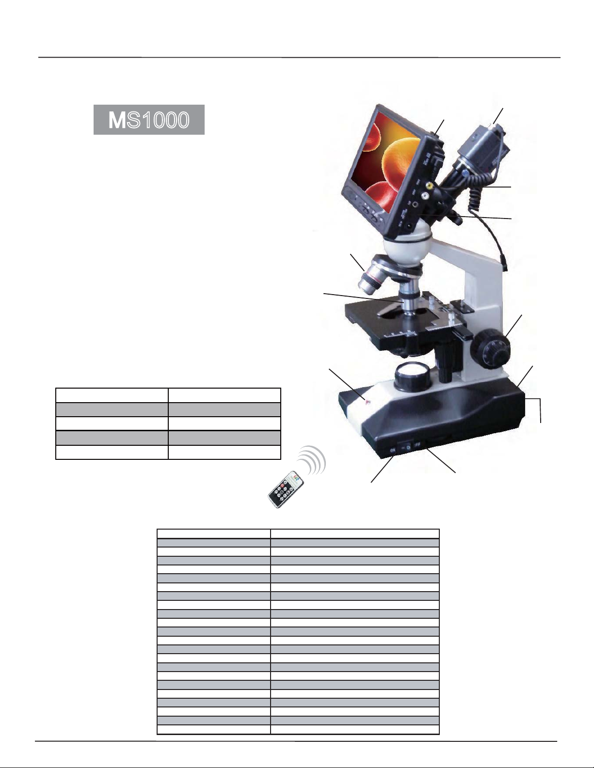
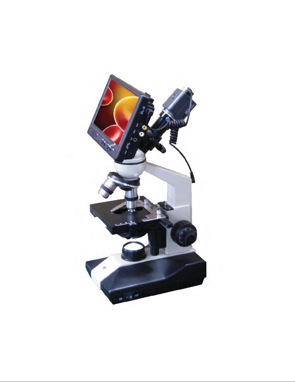
Microscope Standalone Digital Video Recorder
4 Video Output: USB to PC / 2 TV Output / DVR Output
BNC VIDEO OUT
4G SD CARD
MS1000
* 1/3” COLOR CCD 560TVL 0.001Lux
* Functional Microscope DVR
* 2 Lens 4x 10x
* 7” LCD DVR Monitor
* Mpeg 4 Compression format D1 640x480
* Memory Full Overwrite Funtcion
* High Ligh Cold LED.
* Remote Control Included 4GB SD Card
* Rechargeable Li-lon Battery
* USB Capture Software for windows XP
* DC 12V 1000mA
Recording Time
SD Card Capacity Recording Time/h
*%
*%
*%
*%
8 Hours (-/+ 10%)
16 Hours (-/+ 10%)
32 Hours (-/+ 10%)
64 Hours (-/+ 10%)
4X LENS
10X LENS
PC Capture
VIDEO
TO TV
Monitor
ON/OFF
UP / DOWN
RCA Video
to TV
USB TO PC
ITEMS MS1000
TYPE COLOR
PICK-UP DEVICE 1/3” Color CCD IMAGE SENSOR
PICTURE ELEMENTS NTSC: 512Hx492V - PAL: 512Hx582V
HORIZONTAL RESOLUTION 560 TVL
MINI ILLUMINATION 0.001 LUX
HORIZ.SYNC FREQUENCY EIA/NTSC: 15.734Khz - CCIR/PAL: 15.625Khz
VERTICAL FREQUENCY EIA/NTSC: 60Hz - CCIR/PAL: 18.9375
CLOCK FREQUENCY EIA/NTSC: 19.0699 Mhz - CCIR: 18.9375
SCANNING SYSTEM 2:1 INTERLACE
S/N RATIO 46dB
ELECTRONIC SHUTTER 1/1000.000s
LENS 4x 10x
VIDEO OUTPUT 1Vp-p, 75
AU
DIO OUTPUT 2Vp-p (Max)
GAMMA
Rechargeable Li-lon Battery
WEIGHT 14.3 LBS
POWER SUPPLY DC 12V
POWER CONSUMPTION
STORAGE TEMPERATURE -30°C to +60°C
OPERATING TEMPERATURE -10°C to +45\°C
* Specifications are subject to change without notice
LED Light +/-
ON / OFF
Ohms
0.45
4500mA DC12V
800mA
** Designed in U.S.A.
Page 3

Contents
ġ
ġ
ġ
ġ
1. SAFETY PRECAUTIONS .......................................................................................................... 1
2. FEATURES..................................................................................................................................2
3. PACKAGE CONTENT................................................................................................................ 3
4. Smoke DVR Description..............................................................................................................4
4.1 SMOKE DVR LAYOUT .......................................................................................................4
4.2 CONNECTION OVERVIEW ...............................................................................................4
5. Operation...................................................................................................................................... 5
5.1 Power On................................................................................................................................ 5
5.2 Live Mode .............................................................................................................................. 5
5.3 Record Mode.......................................................................................................................... 6
5.4 Playback Mode....................................................................................................................... 8
5.5 PC Playback ........................................................................................................................... 9
5.6 SD Card Maintenance ............................................................................................................ 9
5.7 How to Download the Updated Software ..............................................................................9
6. MENU SETUP...........................................................................................................................10
6.1 Main Menu........................................................................................................................... 10
6.2 Date/ Time ............................................................................................................................ 11
6.3 Motion Detection ................................................................................................................. 11
6.4 Record Setup ........................................................................................................................ 13
6.5 SD Card Options .................................................................................................................. 15
6.6 System Status ....................................................................................................................... 16
6.7 Power On Setup.................................................................................................................... 16
6.8 Factory Default.....................................................................................................................17
7. TROUBLE SHOOTING ............................................................................................................ 18
9. SPECIFICATION....................................................................................................................... 19
The author assumes no responsibility for any errors or omissions that may appear in this
document nor does the author make a commitment to update the information herein.
ġġ
ġ
VER.: 1.0, CD
Page 4
1. SAFETY PRECAUTIONS
ġ
ġġġġġġġġġġġġġġġġ
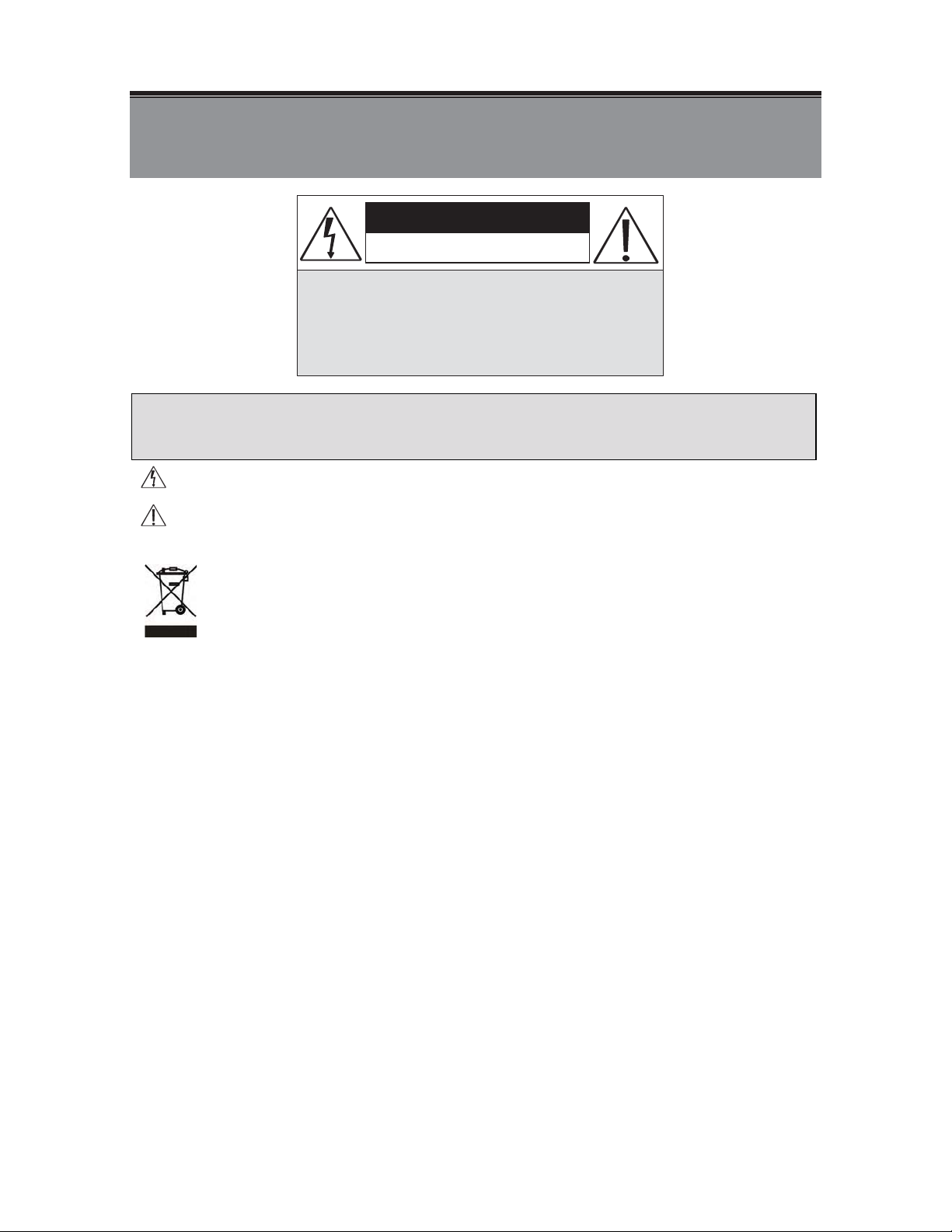
CAUTION :
TO REDUCE THE RISK OF ELECTRICAL SHOCK ,
DO NOT OPEN COVERS (OR BACK).
NO USER SERVICEABLE PARTS INSIDE.
REFER SERVICING TO QUALIFIED
CAUTION
RISK OF ELECTRIC SHOCK.
DO NOT OPEN!
SERVICE PERSONNEL.
It is advised to read the Safety Precaution Guide through carefully before operating the
product, to prevent any possible danger.
WARNING: This symbol is intended to alert the user to the presence of un-insulated “dangerous voltage”.
CAUTION: This symbol is intended to alert the user to presence of important operating and
maintenance (Servicing) instructions in the literature accompanying the appliance.
Disposal of Old Electrical & Electronic Equipment (Applicable in the European Union
and other European countries with separate collection systems).
This symbol on the product or on its packaging indicates that this product shall not be treated as household
waste. Instead it shall be handed over to the applicable collection point for the recycling of electrical and
electronic equipment. By ensuring this product is disposed of correctly, you will help prevent potential
negative consequences for the environment and human health, which could otherwise be caused by
inappropriate waste handling of this product. The recycling of materials will help to conserve natural
resources. For more detailed information about recycling of this product, please contact your local city office,
your household waste disposal service or the shop where you purchased the product.
Do not Plug and unplug the power cord, it may result product malfunction.
Do not install the product in an environment where the humidity is high.
Unless the product is waterproof or weatherproof, otherwise poor image quality may occur.
Do not drop the product or subject them to physical shocks.
Except for vandal-proof or shockproof product, otherwise malfunctions may occur.
Never keep the product to direct strong light.
It can damage the product.
Do not spill liquid of any kind on the product.
If it gets wet, wipe it dry immediately. Alcohol or beverage can contain minerals that corrode the
electronic components.
Do not install the product in extreme temperature conditions.
Use the camera under conditions where temperatures are between 5ɮC (41ɮ F ) ~ 4 5 ɮC.(113ɮ F ) . B e e s p e c i a l l y
careful to provide ventilation when operating under high temperatures.
1
Page 5

2. FEATURES
z The Mini DVR Module supports NTSC or PAL video system, and auto detects video loss.
z The Mini DVR Module is built-in with MPEG4-SP video and G.726 audio codec. It
supports 1 channel video and 1 channel audio recording and playback operation.
z Audio/ Video data are recorded directly on the SD card with FAT16/ 32 file system and
ASF file format. Simple data backup method to a PC.
z Audio/ Video data are recorded directly as ASF file format. You can view the data straight
from your PC, and playback those ASF files with popular media players.
z USB interface that enables data to be transfer to a PC.
z For 1 GB SD card, the record time is about 5 hours at Standard Quality for NTSC: 30 fps
@ 352 x 240 and PAL: 12 fps @ 640 x 480.
z The DVR supports: Manual, Motion Detection, Schedule, and Alarm Recording mode
with independent video size, quality, and frame rate set up.
z Schedule Record (Schedule Record Priority Order: Alarm/ Motion Detection/ Continuous)
and IR Illuminator can be setup to ON/ OFF and per hour.
z Support external alarm signal connection to enable alarm trigger recording.
z For motion detection, multiple detection blocks and appropriate motion trigger level
set-up.
z Support key lock function.
z Use anywhere, the device supports either DC power adaptor.
2
Page 6
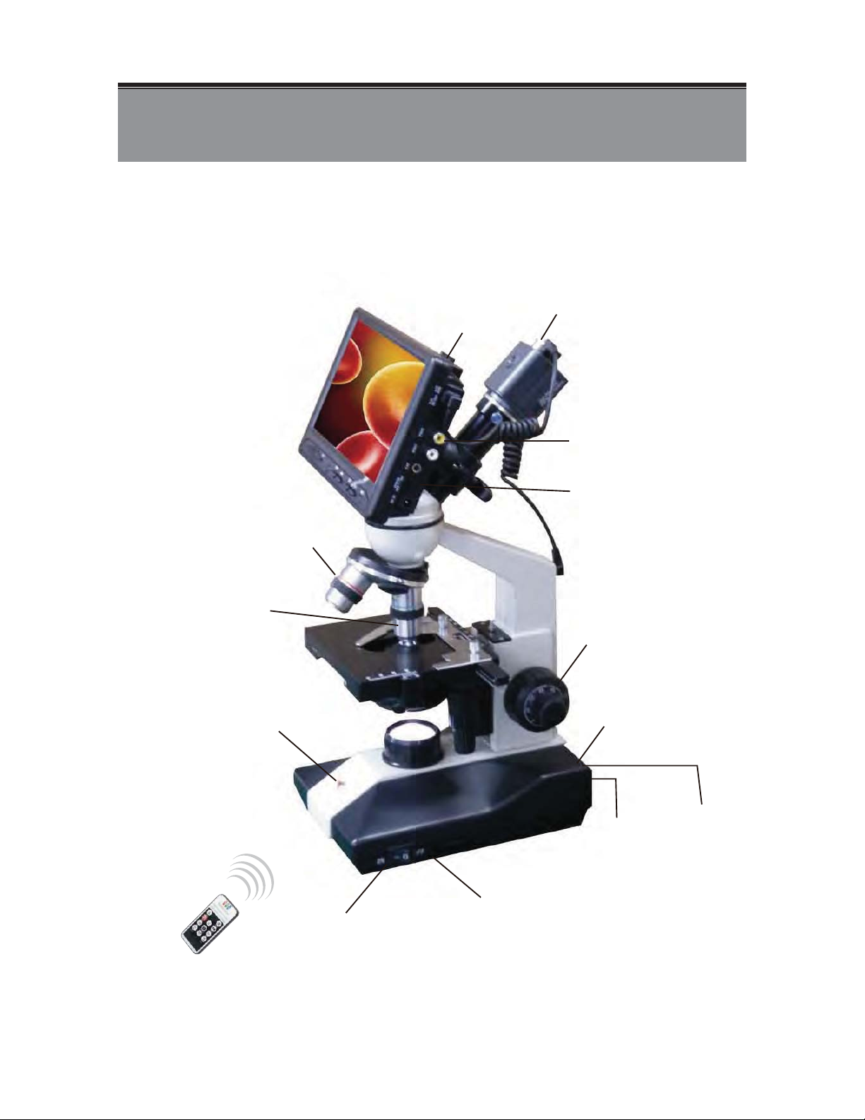
4. Microscope DVR Description
4.1 DVR Layout
BNC VIDEO OUT
4G SD CARD
4X LENS
VIDEO
TO TV
Monitor
ON/OFF
10X LENS
PC Capture
UP / DOWN
RCA Video
to TV
Charger
USB TO PC
LED Light +/-
ON / OFF
4
Page 7
5. OPERATION
ġ
5.1 Power On
1. To power-up, connect to a DC 12V power input connector.
(NOTE 1: Each time after power-on, the system auto-detects its peripherals. When the REC LED
flashes indicate that the SD card is proceeding testing (complete boot time is several seconds)
When an image file error has been detected, the system will initiate auto repairing.
2. After power on, the system auto enters live monitoring. When the system is
currently under schedule recording, it auto enters record mode.
3. “
4. When SD card is not inserted or problem occurs on the SD card. Rec indicator will
5. You can play while the SD card is “read only”, but you cannot record; and Rec
6. After power-loss the system auto returns to the previous recording mode.
Do not withdraw the CF card while booting. It may destroy the data stored within the CF card.
” icon shown on the status line, indicates that SD card is operating normally.
flash quickly. Please re-format before proceeding.
indicator will flash quickly.
5.2 Live Mode
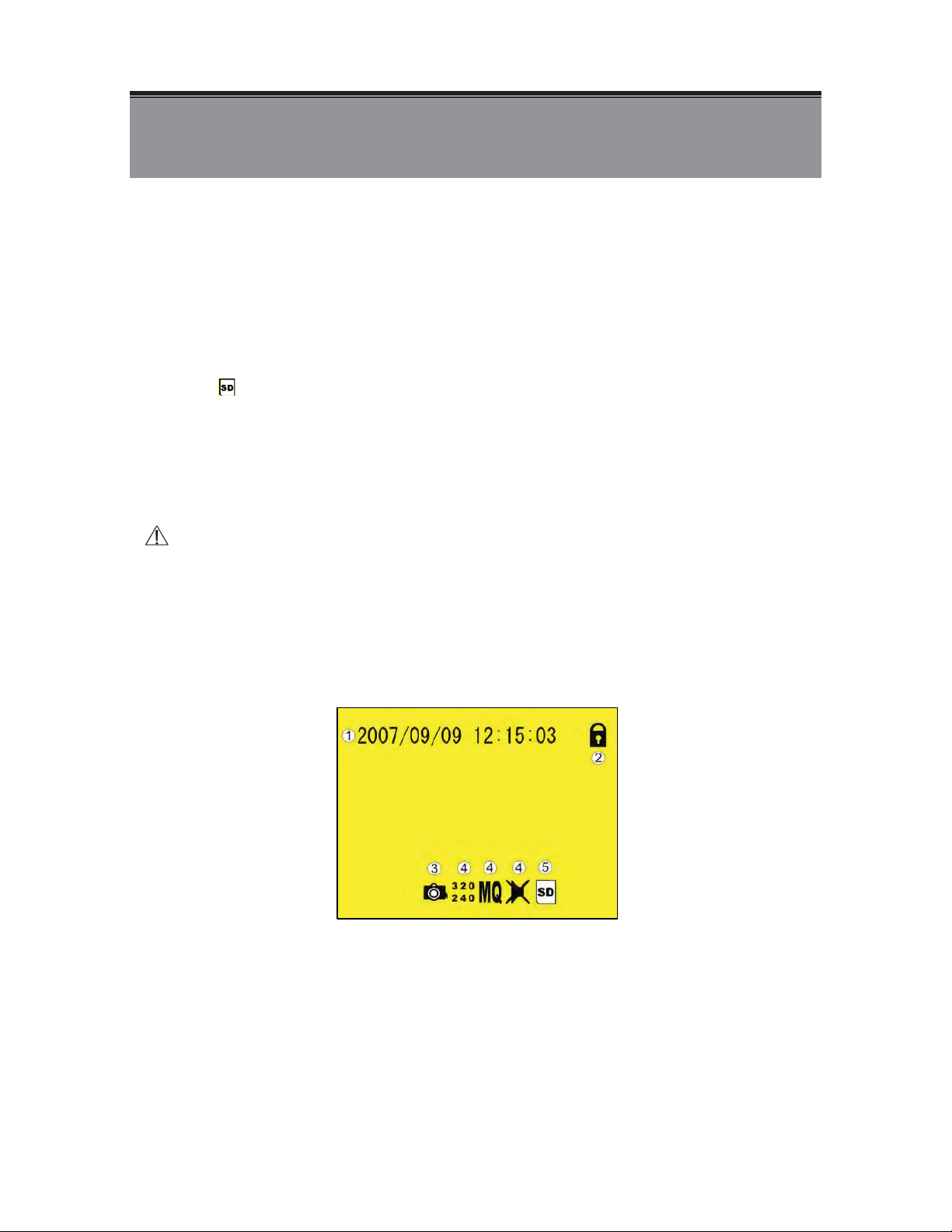
Live mode is the default setup after system start-up.
c Time Display: System Date and Time.
NButton Lock: Indicates all buttons are locked (buttons are ineffective).
OVideo Status: Indicates external camera connection.
5
Page 8

P Record Status: Manual Record Parameter.
;
ɶ
İ
Record Size, please refer to˰7.4 Record Setup˱for VIDEO SIZE
烉
setup.
Record Quality, please refer to˰7.4 Record Setup˱for VIDEO QUALITY
烉
setup.
Audio Off Record, please refer to˰7.4 Record Setup˱for AUDIO
烉
RECORD setup.
Q SD Card Status:
烉
SD Card has not been inserted or malfunction.
烉
SD Card is proceeding file testing.
烉
SD Card is functioning normally.
烉
Overwrite record.
When SD card is not inserted, record and playback function is inapplicable, but
monitoring is applicable.
5.3 Record Mode
1. Start Record: 3 Types of recording mode.
(1) Manual Record: Suitable to record at anytime. Press˪Rec ˫button, to enter
manual recording status (start recording). For more information, please refer to
˰7.4 Manual Record & Schedule Record˱.
(2) Motion Detection Record: Suitable to record, when there are severe image
changes. Motion detection triggers schedule recording, but it will only start
recording when the variation exceeds the alarm limitation value. For more
information, please refer to˰7.3 Motion Detection˱and˰7.4 Manual Record &
Schedule Record˱.
(3) Continuous Record: Suitable for few constant frame recording or on long-term
continuous recording. For more information, please refer to˰7.4 Manual Record
& Schedule Record˱.
(4) Alarm Record
been setup, alarm icon will be shown on the display status bar (alarm triggered
recording is setup).
2. Stop Record:
Manual Record
Schedule Record
Suitable for external alarm recording. When alarm schedule
Press˪İɶ
System Power Shortage. !
Enter˪
Motion Detection/ Continuous) will be stopped.!
˫button/ Manual Power-Off/ Auto Power-Off when
II ˫schedule recording, all kinds of recordings (Alarm/
To continue recording, please follow the methods below to restart recording.
Manual Record
Schedule Record
Repress˪ ˫button.
Stop playback and the system will auto re-check the record
schedule setup again.
6
Page 9

3. Record Display:
M Record Status:
: Indicates recording is in progress.
N Record Mode:
烉Manual Record 烉Schedule Record
!
烉Motion Detection Record 烉Alarm Record
!
O Record Storage Mode Status:
!
!
烉Continuous Record
烉Remaining Storage Capacity
%
4 System recording is determined according to the recording priority order (Record Priority:
Manual/ Alarm/ Motion Detection/ Continuous).
5. Different recording modes may have different kinds of setups. Basic setup: video size,
recording frames, video quality, and audio recording. When different recording modes are
triggered, the system starts recording according to the different setup. This kind of design
provides flexibility to ensure efficient recording time and quality. Example: Work hour
from 8:00am to 6:00pm, setupˬSchedule Record˭to low video quality with less recording
frames to extend the recording time. And off work hour, setup ˬMotion Detection
Record/ Alarm Record˭ to enable high video quality with the highest recording frames,
when an event occurs.
7/!Video or audio may be recorded into the SD card (SD card is purchased separately). !
Do not withdraw the SD card while recording. It may destroy the data stored within the SD card..
Power loss during recording results incomplete videos or errors.
Video loss during recording, the system stops recording, backups the files, and when
the videos are normal again, the system will continue recording.
7
Page 10

5.4 Playback Mode
ɶ
Selectable Playback format: Continuous Playback and Searching Playback.
(1) Normal Playback: Press˪/˫button to first playback the final recorded data, and then
according to the SD card file recording order.
M Playback Status:
` 烉Press˪/˫button once to playback, press it again to pause.
烉Press˪˫or˪˫button to Fast Rewind or Fast Forward (Speed:
x2/ x4/ x8/ x16/ x32). Press˪/˫button to return to normal speed
playback.
II 烉During playback, press˪/˫button to pause playback and press
again to return to playback status.
Press˪İɶ
(2) Search and Playback: Enter MENU and select˰SEARCH AND PLAY˱item.
MFile directory shows dates and the amount of contents under the directory. The
NCurrent location page.
烉During pause, press˪˫or˪˫button to step back one frame or
to step forward one frame and press˪/˫button to return to
normal speed playback.
˫button to stop playback function and to return to live status.
user may press˪˫or˪˫button to move the cursor up or down.
OEvent Record Status Icon:
8
Page 11

烉Manual !! 烉Motion Detection!! 烉Continuous ! 烉Alarm
ɶ
NOTE 1 & NOTE 2).
(
PEach color distinguishing different recording events, the user may press˪˫or
˪˫button to move the cursor left or right and immediately shows the first
image of the highlighted event on the screen display background.!
QDisplays the time highlighted by the event bar.!
(NOTE 1烉Select the starting point and press˪Enter˫button to playback.
(NOTE 2烉Press˪İɶ
and PLAY˱selection and enables the user to select the prefered input source.
The device supports playback only to images recorded by our device, other ASF video
files are not guaranteed.
˫button to stop playback and the system will return to˰SEARCH
5.5 PC Playback
1. The device uses SD card as its main storage. User may read the data stored in the SD
card from the computers that supports SD card reader device.
2. All files (under DVMPG4 folder) has approximate size of 1MB and file names are
ordered according to recorded times (sequence).
File Playback: User may use Microsoft£炼Media Player or DivX炼DivX Player
(http://www.divx.com/) to playback video files.
When first time using Media Player to playback, it requires the most updated decoder
from the Microsoft£ software website.
5.6 SD Card Maintenance
1. The device supports only FAT16/ 32 file system; therefore it is unable to determine
other file systems. Please format the SD card (enter˰MENU/ SD CARD OPTIONS˱
and select “Format”).
2. The system supports only partial SD card file system repair. The system is unable to
detect any file system damage, therefore please format the SD card (enter˰MENU/
SD CARD OPTIONS˱and select “Format”).
5.7 How to Download the Updated Software
1. Use the SD card to update your system firmware.
2. Please follow the steps below to update the software:
(1) Copy the new system firmware into the new directory of the SD card from your
computer.
(2) Insert the SD card; switch off the main power and then restart.
(3) Wait for 5 to 6 seconds, the system update will be complete and return to live mode.
Do not withdraw the SD card while booting, when power-loss occurs while proceeding step
(3), please repeat step (2) and (3).
9
Page 12

6. MENU SETUP
ġ
ɶ
6.1 Main Menu
MMAIN MENU: Item subject.
NMenu Layer Indication: The device consists of three menu layers.
ˍ
ˍˍ
ˍˍˍ
O MENU Content: Basic Menu Operations.
Press˪˫or˪˫button, to select the item.
Press˪ENTER˫button, to enter the sub menu (烍).!
Press˪İɶ
Under second or third menu layer, the system will return to the previous menu
layer (second layer to first layer or third layer to second layer).
Under main menu (first menu layer), the system will enter live mode. Press˪˫
or˪˫button, to increase or decrease the setting value of the item selected
(
NOTE 1).
: First Menu Layer (Main Menu)
: Second Menu Layer
: Third Menu Layer
˫button:
(
NOTE 1: All words underlined and bold indicatesˬDefault Value˭.
10
Page 13

6.2 Date/ Time
M
N
y
İ
İ
Date Format
Date/ Time Adjustment
6.3 Motion Detection
1. Window Setup:
Y / M / D
烉
Year Setup: 2000 - 2099
烉
Month Setup: 01 - 12
Time Setup: 00 : 00 - 23 : 59
Return to factor
M / D / Y D / M / Y
default, no changes will be made.
M Detection Block: Formed by two or more cells.
N Cursor: Press˪
O Detection Cell: The whole screen is divided into 16x12 cells.
P Detection Block.
2. Cursor Movement: Press˪
press˪//İ˫button to move the cursor freely.
II˫button to switch to Select/ Edit mode.
II˫button to switch to setup mode (cursor color is black),
11
Page 14

3. Motion Detection Area Setup:
İ
İ
M
N
(1) Press˪
II ˫button to edit detection block.
Q Mode
CELL EDIT
DEL BLOCK
DEL ALL
ADD BLOCK
ADD ALL
(2) Press˪
Single detection cell setup (detection/ non-detection)
Disable a block
Delete all cells
Enable a block
Enable all cells
II ˫button to switch cursor to edit mode (cursor color is pink). Press
˪//İ˫button, follow step (1) to change the size of the detection block.
(3) Detection area is shown by color red, press˪Enter˫to enable/ disable the
detection block.
4. Motion Detection Sensitivity Setup:
Changing the alert value may affect the recording sensitivity of the Motion Detection.
MD ENERGY
MD THRESHOLD
烉
Reveals current sensitivity rate (
Reveals user sensitivity rate setup. Press˪˫or˪˫
烉
NOTE 1).!
button, to change the motion detection threshold level
(
NOTE 2).!
(NOTE 1: Motion detection is triggered when MD ENERGY level exceeds MD THRESHOLD level
(red block).
(NOTE 2: The red cells reveals the setup made by the user.
12
Page 15

6.4 Record Setup
M
N
O
P
Selectable manual or schedule recording, basic setups are shown below:
1. MANUAL RECORD: Press ( ) button to start recording (
MVideo Size/ Frame Rate Setup:
VIDEO SIZE 320x240
640x480
FRAME RATE (MAX) 30 fps 12 fps
NImage Quality:
HIGH Using high recording quality (More CF card storage capacity will be required).
MEDIUM Using medium recording quality.
LOW Using low recording quality (Less CF card storage capacity will be
required).
OAudio Record: Enable
or disable audio recording.
(NOTE 1: Menu setup is inapplicable during manual recording.
NOTE 1).
2. SCHEDULE RECORD (Alarm Detection/ Motion Detection/ Continue): Records only
within the setup time range.
烉
SCHEDULE SETUP
ALARM RECORD
MOTION RECORD
CONTINUE RECORD
Enable/ Disable schedule and record mode setup.
烉
Alarm setup.
烉
Motion detection setup.
烉
Continuous setup.
13
Page 16

(1) SCHEDULE SETUP烉
M
N
M
N
M
SCHEDULE 烉Record ON / OFF setup (default setup is OFF).
SCHEDULE MODE 烉Press˪˫or˪˫to setup schedule time. Press˪˫ or˪˫
to setup different types of recording schedule. ( 烉Motion Detection
Record!!
烉Continuous Record!! 烉Alarm Triggered Record).
(2) Increase setup during Alarm Detection:
DURATION 烉Duration time when motion detection has been triggered (05 ~ 90
SEC (increase by every 5 SEC) / 10 SEC).
ALARM INPUT 烉Alarm trigger method (N.C./N.O.).
(3) Increase DURATION setup during Motion Detection Record:
CONTINUOUS RECORD 烉Continuous record time when motion detection has
been triggered (05 ~ 90 SEC (increase by every 5
SEC) / 10 SEC
14
).
Page 17

(4) CONTINUE RECORD:
M
N
Setup method is similar to manual record setup, for more information please refer to [7.4 1.
MANUAL RECORD].
6.5 SD Card Options
TOTAL SPACE 烉SD card total capacity.
REMAIN SPACE烉SD card remaining capacity.
(NOTE 1: Proceeding continuous recording, old videos can be deleted and overwritten. Please confirm before
setup.
(NOTE 2: Recording time depend on the SD card capacity, different recording modes, and degree of video
variation.
ġ
ġ
ġ
ġ
ġ
ġ
ġ
ġ
ġ
ġ
ġ
ġ
15
Page 18

6.6 System Status
M
N
Press any button to return to the Main Menu.
6.7 Power On Setup
LANGUAGE 烉 Setup menu language.
COMPOSITE烉Setup video output format, NTSC/ PAL (NOTE 1).
(NOTE 1: Connect the camera, the device auto detects NTSC/ PAL video system (the output video system
will be setup the same as its input video system). Without connecting the camera, the video system setup
will be the same as its previous setup.
16
Page 19

6.8 Factory Default
ɶ
Press˪Enter˫button, returns all settings to the factory default value (NOTE 1).!
Press˪İɶ
(NOTE 1: Return to factory default will erase all configuration values and return to the Factory Default
values炷except Date and Time setup炸. Therefore, confirm before you proceed.
˫button, exit this screen display and returns to the Main Menu.!
!
17
Page 20

7. TROUBLE SHOOTING
Q1. What is the recording capacity for 1GB SD card?
A1. Different recording setup has different recording capacity. Table below shows possible
recording time during continues recording applying different record mode.
Quality Frame Rate SD Card High Medium Low
VGA (640 x 480)
QVGA (320 x 240)
Q2. Why does the system auto reboot during normal operation?
A2. It indicates that the SD card error has been detected. To enable data completeness,
monitoring procedure will reboot the device. After device reboot the system returns to the
status before reboot (Ex.: returns to Manual Record or Schedule Record).
Q3. Why won’t the drag scroll work when playback on PC?
A3. To solve this problem, please download “AsfTools” (http://www.geocities.com/myasftools).
12 FPS 1 GB 155 min 280 min 340 min
30 FPS 1 GB 150 min 380 min 600 min
18
Page 21

9. SPECIFICATION
ġ ġ
炻
ɗ
ɗ
System NTSC / PAL Video System and Video Loss Auto Detection
Codec MPEG4-SP ASF File Format
Record Frame Rate
Video
Record Quality Low / Medium / High
Recording Date/Time Overlay with Video Images in ASF File
Input 1 CH Composite Video Line In
Output 1 CH Composite Video Line Out
Sampling Rate 44.1 KHz
Audio
Audio Device
Storage Media SD Card (FAT16/ 32) MAX FILES: 16384 FILES
Serial Port USB 1.1 (Read-Only)
Recording Mode Manual / Schedule ( Alarm / Motion Detection / Continue)
Motion Detection Setting Multiple Blocks and adjustable sensitivity
Event Search Function Property and first image of selected file is displayed
Playback Function Play/Fast Forward/Fast Rewind/Pause/Step Forward/Step Backward
Playback Speed x1/ x2/ x4/ x8/ x16/ x32
Power Supply DC 12V/1A
Dimensions 38 mm (W) x 17.5 mm (H) x 38 mm (D)
Operating Environment
Storage Environment
Codec G.726/ 32 kbps
Input 1 CH Audio Line In
Output 1 CH Audio Line Out
STANDARD FUNCTION
1, 2, … , Maximum fps selectable
Maximum:
30 fps@320x240 / 12 fps@640x480
Microphone
30%~80% RH, 5
30%~90% RH, 0
Speak炻Earphone
~ 45ɗ (41ə ~ 113ə)
~ 50ɗ (32ə ~ 122ə)
(Note: Design and Specifications are subject to change without notice.)
19
 Loading...