

Page 1
SDI Monitor with WIFI DVR and local DVR.
MC22SDI
User’s Manual Instructions
7/17/2012
Page 2
Risk of Electric Shock, Do not Open
CAUTION: TO REDUCE THE RISK OF ELECTRIC SHOCK, DO
NOT REMOVE COVER NO USER-SERVICEABLE PARTS
INSIDE REFER SERVICING TO A QUALIFIED SERVICE
PERSON
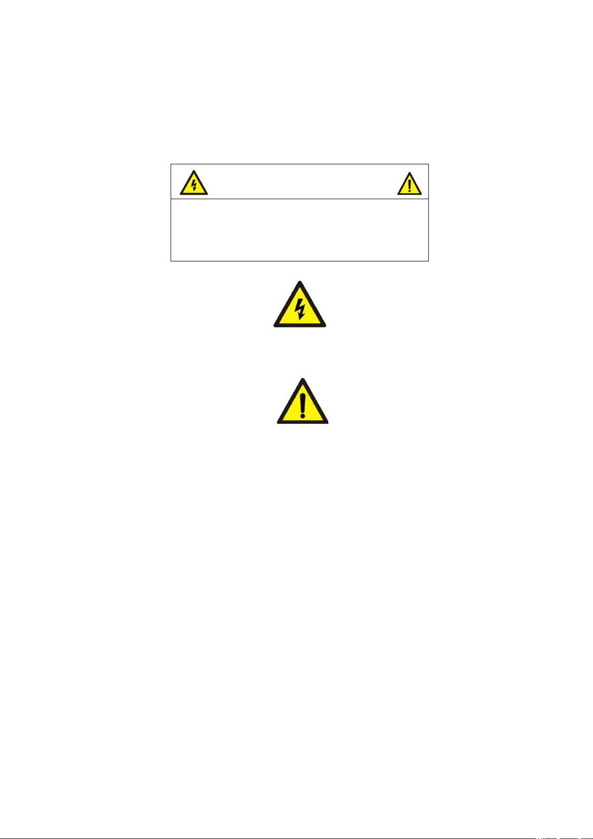
Safety Precautions:
DO NOT ATTEMPT TO DISASSEMBLE THE DEVICE.
This symbol is intended to alert the user to the presence of non-insulated dangerous voltage within the
product’s enclosure that may be of sufficient magnitude to constitute a risk of electric shock to persons.
This symbol is intended to alert the user to the presence of important operation and maintenance
instructions in the literature accompanying the appliance.
Warning!
1. This product has patented for configuration and appearance design, and copying is not permitted.
2. If this product fails to operate normally, contact authorized distributor or a service center. Never disassemble or modify the product in
any way. Problem caused by unauthorized user disassembly or repairs voids the warranty.
3. Electromagnetic fields in specific frequency may cause image interference.
4. Be sure to use only the standard adapter which is specified in the specification sheet. Using other adapter could cause fire, electric
shock or damage to product.
5. Connecting the power supply incorrectly may result in fire, electric shock or damage to the product as well.
6. Do not connect multiple cameras to a single adapter. Exceeding the capacity may cause abnormal heat causing fire.
7. Securely plug the power cord into power receptacle. Any loose connection may result in fire.
8. When installing the camera on a wall or ceiling, fasten it safely and securely. A falling camera may cause personal injury.
9. Do not place conductive objects (e.g. screwdrivers, coins, metal things, etc.) or containers filled with water on top of the product.
10. Do not install the unit in humid, dusty, or sooty locations. Doing so may cause personal injury.
11. If any unusual smell or smoke comes from the unit, please stop using the product. In such case, please immediately disconnect the
power source and contact local authorized distributor or a Service Center.
12. When cleaning, do not spray water directly onto parts of the product, or may cause fire or electric shock. Gently wipe the surface with a
dry cloth. Never use detergents or chemical cleaner on the products, or may cause fire or electric shock.
Page 3

Cautions
1. Do not drop objects on the products or apply strong shock to it. Keep it away from a location subject to excessive vibration or magnetic-field
interference.
2. Do not install in a location subject to high temperature (over 122°F or +50℃ ), or low temperature(below 14°F or -20℃), it may cause fire.
3. If you want to relocate the installed products, be sure to turn off the power before moving or reinstalling it.
4. Remove the power plug from the outlet when there is a lightning storm. Neglecting to do so may cause fire or damage to the product.
5. Avoid a location which is exposed to direct sunlight, or near heat sources. Neglecting to do so may cause fire.
6. Install in a well-ventilated location.
Important Safety Instructions
1. Read these instructions.
2. Keep these instructions for later use.
3. Pay attention that all warnings should be adhered to.
4. Follow all instruction.
5. Do not use this product near water.
6. Clean only with dry cloth.
7. Do not block any ventilation openings.
8. Do not install near any heat sources such as radiations, heat registers, or other product (including amplifiers) that produce heat.
9. Protect the power cord from being walked on or pinched particularly at plugs, convenience receptacles, and the point where they exit from
the apparatus.
10. Only use attachment/accessories specified by the manufacturer.
11. For added protection for this product during a lightning storm, or when it is left unattended and unused for long periods of time, unplug it
from the wall outlet and disconnect the antenna or cable system.
12. Refer all servicing to qualified service personnel. Servicing is required when the product has been damaged in any way, such as
power-supply cord or plug is damaged, liquid has been spilled or objects have fallen into the product has been exposed to rain or moisture,
does not operate normally, or has been dropped.
13. Do not operate the device beyond its temperature, humidity or power source ratings. Operating temperature: 14F-122F(-20℃- 50℃);
Humidity﹤85%。
Page 4

Table of Contents
Chapter 1 - Overview
1.1 Introduction
This is a user’s manual for the Camera, Monitor, DVR and WI-FI from this product.
1.2 Package
1.2.1 - SDI Monitor with DVR / WiFi DVR / SDI Camera Built-in.
1.2.2 - Remote Control for the Monitor / Remote Control for the DVR.
1.2.3 -
1.3 Specification :
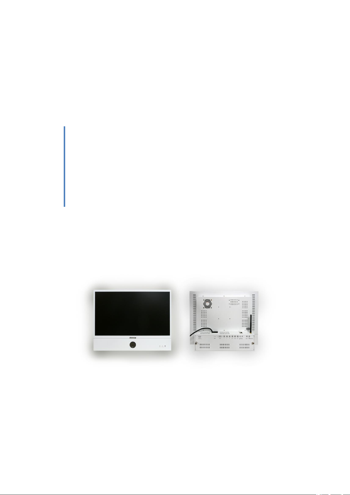
1.4 Panel
1.4.1 Front:
LCD Screen、Camera、REC led、POWER led、IR led
1.4.2 Side:ON/OFF Switch
1.4.3 Back Top:Reset Button,RJ45 jack,Antenna input;
1.4.4 Back (from left to right) HDMI, VGA IN, Y, Pb, Py, VIN1, VIN1.4, V Out, Audio in 1/1.4,
1.4.5 Back Bottom:DVR SD Card, mic, mic, WiFi SD Card
1.4.6 Remote Control :
POWER:ON/OFF
MUTE:ON/OFF
PICTURE:MODE: ( USER T / STANDARD / L-LIGHT / H-LIGHT)
FREEZE:PICTURE FREEZE
INPUT:PC – N/A
HDMI – SDI CAMERA
AV – SDI CAMERA LOWER RESOLUTION
AV2 – DVR with SD CARD
YPBPr – N/A
MENU:MONITOR OSD MENU
Page 5
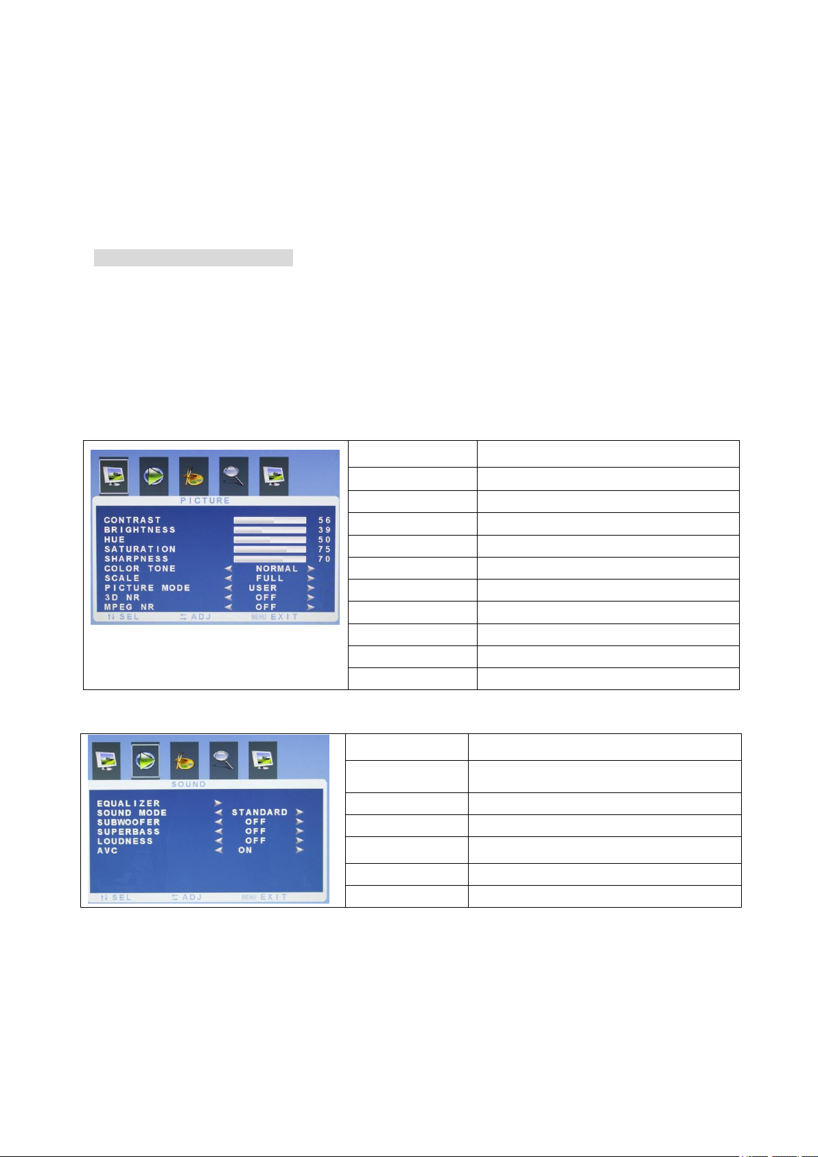
ITEM
OPTIONS
CONTRAST
1-100
BRIGHTNESS
1-100
HUE
1-100
SATURATION
1-100
SHARPNESS
1-100
COLOR TONE
NORMAL/WARM/COOL
SCALE
FULL/ZOOM/ZOOM2/NORMAL/14:9
PICTURE MODE
USER/STANDARD/L-LIGHT/H-LIGHT
3D NR
OFF/LOW/MID/HIGH
MPEG NR
OFF/LOW/HIGH
ITEM
OPTIONS
EQUALIZER
120HZ/500HZ/1K5HZ/5KHZ/10KHZ
SOUND MODE
USER/STANDARD/MOVIE/MUSIC
SUBWOFFER
OFF/ON
SUPERBASS
OFF/ON/1/2
LOUDNESS
OFF/MODE1/MODE2/MODE3/MODE4
AVC
OFF/ON
VGA:N/A
YPbPr: N/A
HDMI: SDI CAMERA
AV :AV
S-VIDEO:N/A
DVI:N/A
Chapter 2 - Monitor Operation
2. 1 Start
Plug the power cord,
Turn the Switch ON and the GREEN LED indicator will turn on
2.2 Menu
Monitor Screen Menu: (Picture, Sound, System, Advance, PIP)
2.2.1 Picture
2.2.2 Sound
Page 6
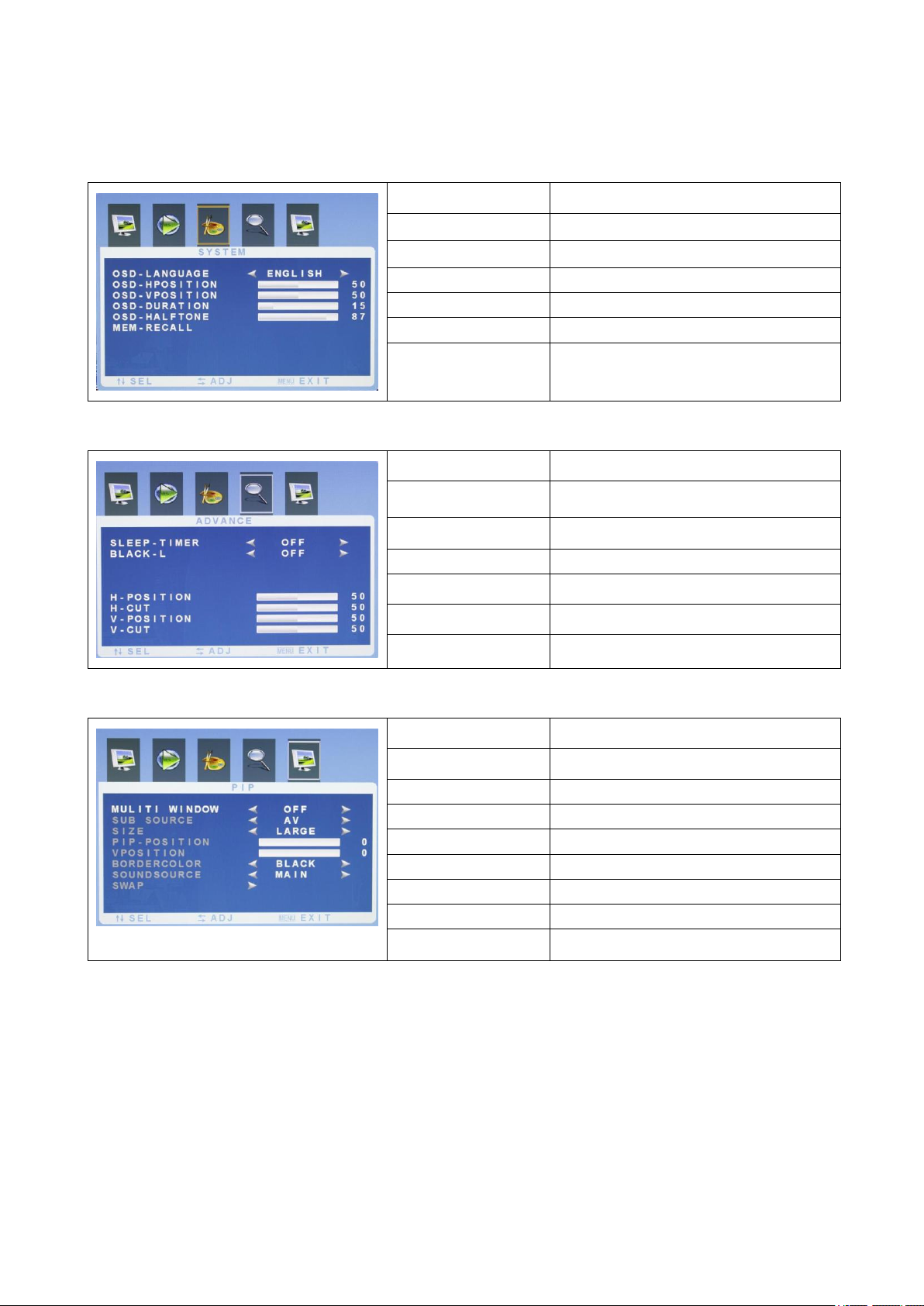
ITEM
OPTIONS
OSD-LANGUAGE
ENGLISH/CHINESE
OSD-HPOSITION
0-100
OSD-VPOSITION
0-100
OSD-DURATION
0-100
OSD-HALFTONE
0-100
MEM-RECALL
ITEM
OPTIONS
SLEEP-TIMER
OFF/15M/30M/45M/60M
BLACK-L
OFF/LOW/HIGH
H-POSITION
1-100
H-CUT
0-100
V-POSITION
0-100
V-CUT
0-100
ITEM
OPTIONS
MULITI WINDOW
OFF/PIP/PIP FULL
SUB SOURCE
AV/AV2 (PIP/PIP FULL ON)
SIZE
LARGE/MID/SMALL (PIP ON)
PIP-POSITION
1-100 (PIP ON)
VPOSITION
1-100 (PIP ON)
BOARDERCOLOR
BLUE/BLACK
SOUNDSOURCE
MAIN/SUB
SWAP
2.2.3 System
2.2.4 Advance
2.2.5 PIP
Page 7
Chapter 3 WIFI / IP DVR Operation
3.1 IP/WIFI Camera/DVR / Configuration
3.1.1 System Requirements:
- Internet Explorer 6.0 or above
- DirectX 9.0 or above
3.1.2 Client Network Settings:
Note: Your computer must be in the same network address range with the video server to communicate,
therefore you may need to change the IP address of the video server before you can login to the server. Please
follow these instructions:
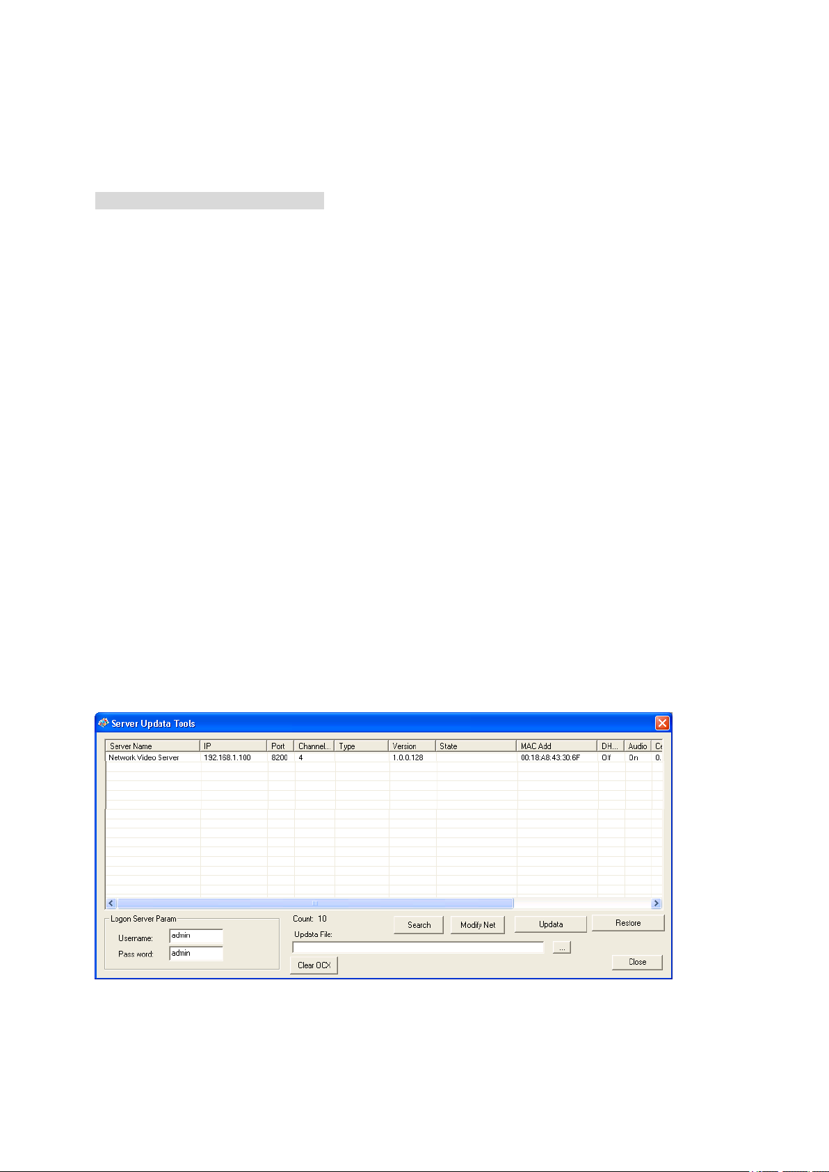
Step 1: Install the Network Video Client Software
Insert the software disk to the CD-ROM, you will see the NVClient Software installation file, run the
program. After the installation, click ―Start‖ – ―Programs‖ – ―Digital Video Management Center‖ – then
run ―Server Tools V2‖ as follows
Step 2: Click search to search the video servers, choose the server and click ―Modify Net‖, a dialog will
show up as below:
Page 8
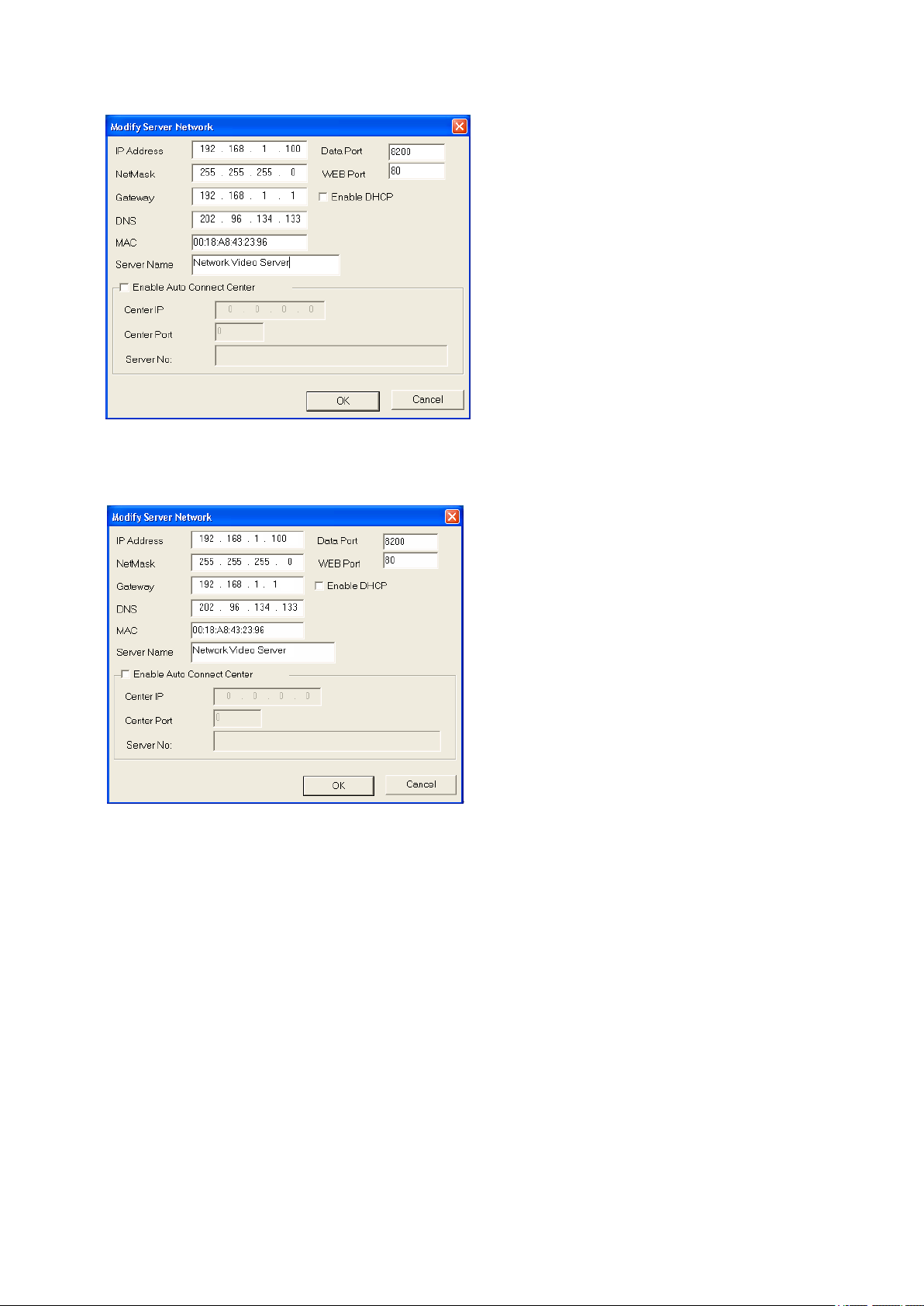
Step 3: Modify the IP address (example: modify the address to 192.168.168.72), see the example
below:
3.2. Video encoder login and Interface function description
3.2.1 Login the video encoder via the NVClient software
3.2.1.1 Steps of login
Step 1: add an IP address to computer so as to access DVS/IP Camera, for example: 192.168.1.99.
Step 2: Login client side, in Windows operating system, click ―Start‖ → ―Program‖ → ―Digital Video
Management Center‖ menu, click ―NVClient‖, type user name ―admin‖, password ―admin‖ then press
―OK‖ to enter to the program.
Page 9
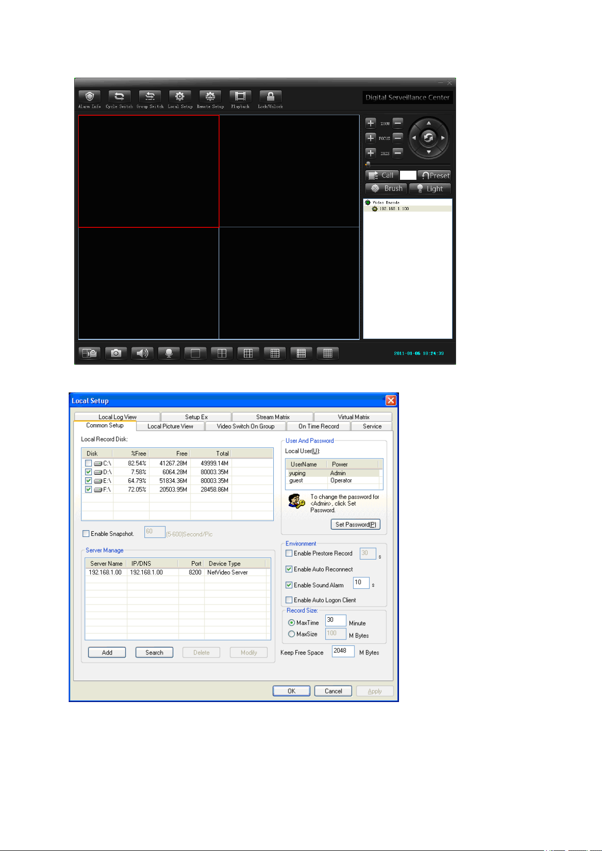
Click on『Local Setup』on the menu bar:
Please follow the steps below to add a DVS/IP Camera into a local LAN:
Click『Search』button to locate the IP of the device.
Page 10
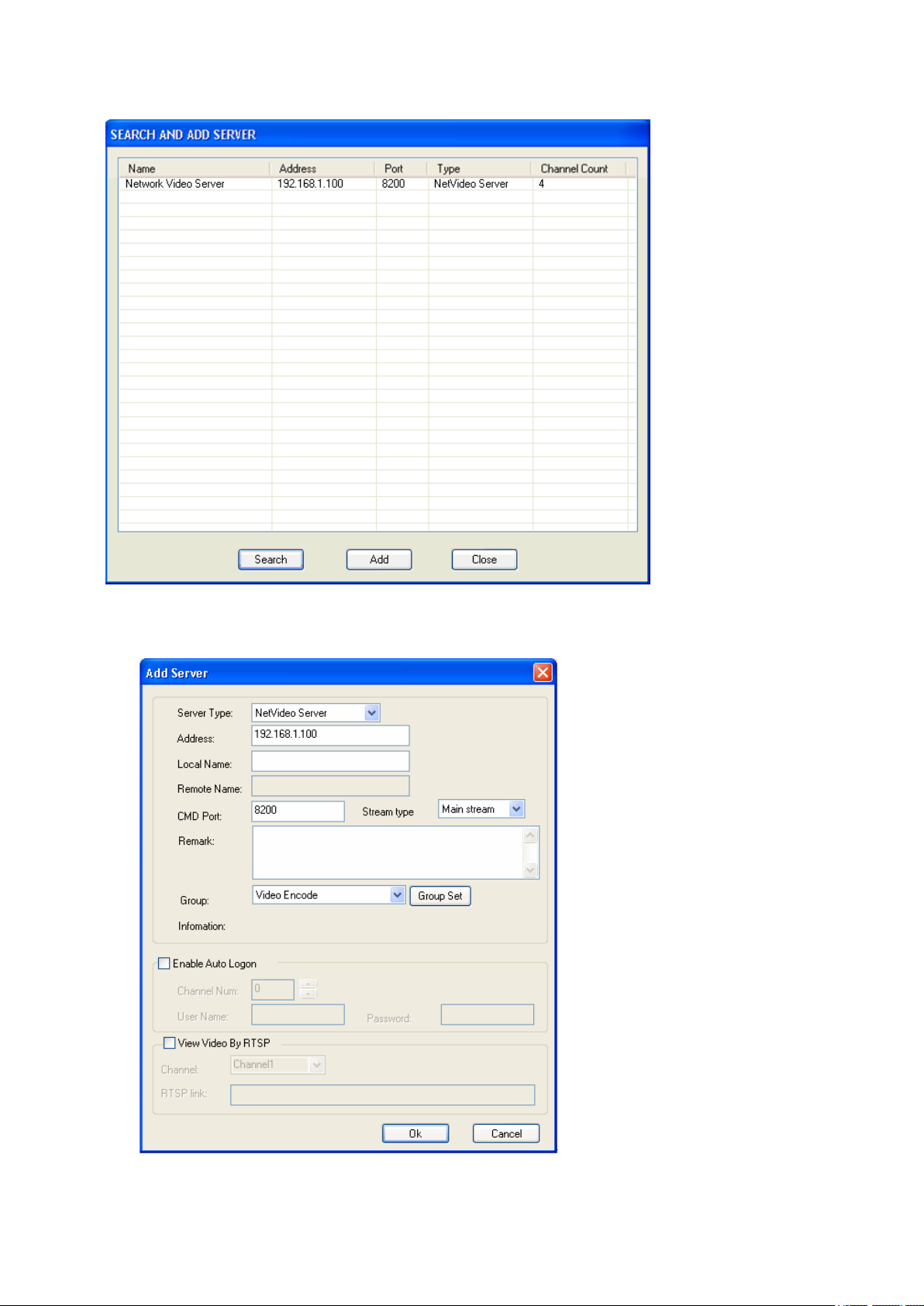
Step 1: select the device to be added in the search list
Step 2: click on『Add』button.
Page 11
Step 3: Type Local Name defined by user.『Enable auto login server』, when you login the server
next time, you won’t need to retype a username and password.
Step 4: After the setting are done, return to the main page of the software, double click the added
device in the device list, and then double click the channel below the device to see the video.
3.3 Login the video encoder via Internet Explorer
Step 1: Run the IE, type-in the IP address of the server in the address line e.g. http://192.168.168.72 as
shown below, the system will ask for permission to install the plug-in
Page 12
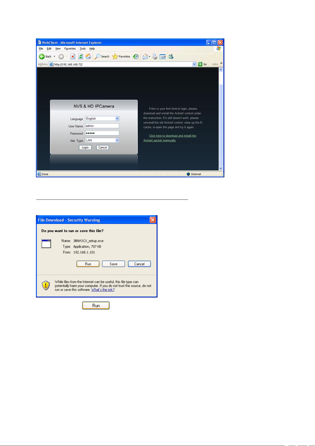
Step 2: If this your first time to login, please click download link:
Click here to download and install the ActiveX packet manually.
a dialog will pop up as below:
Step 3: Click button, a dialog will pop up as bellows:
Page 13

Step 4: Click button and button to finish install.
Step 5: Input ―username‖ and ―password‖ and then click button.
Note: the default login is ―admin‖, password is ―admin‖
Step 6: Click button to open video channel.
Page 14

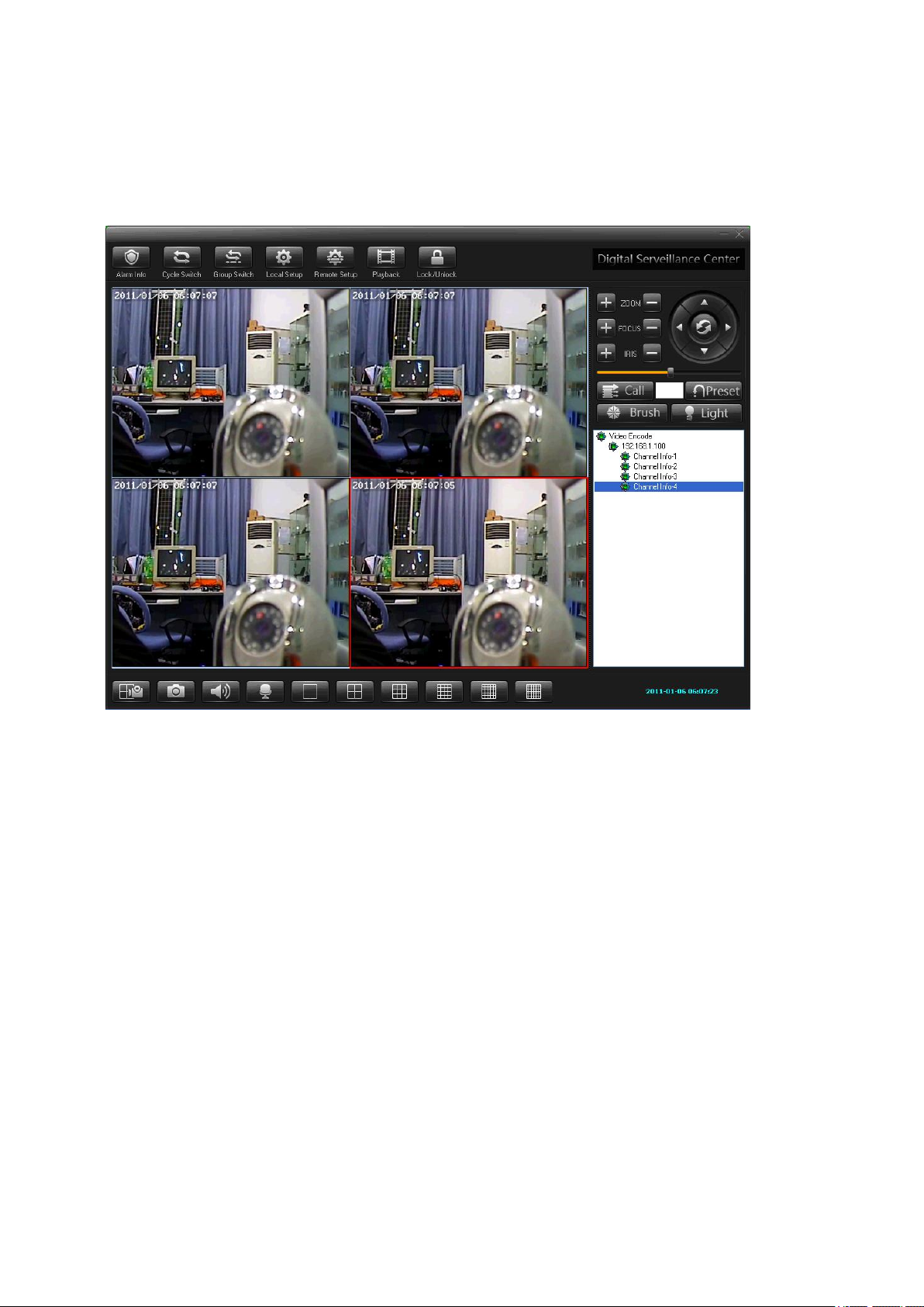
3.4 Web client Interface function description
Click this button to open or close channel picture.
Click this button to carry out snapshot to front end video.
Click this button to enable talkback function with front end DVS/IP Camera.
Click this button to enable talkback function with front end DVS/IP Camera.
Click this button to switch between audio enable and disable.
Click this button to enable rain strip function.
Click this button to enable lighting function.
N/A for this model
Page 15

N/A for this model
N/A for this model
Click this menu to switch to real time preview interface
Click this button to switch to record playback interface
Click this button to pop up parameters setting diagram
Click this button to exit login
3.5. Video Decoder login and configuration
Decoder default network parameter:
IP Address:192.168.1.[[[
Subnet mask:255.255.255.0
Default gateway:192.168.[.[
DNS server:xxx.xxx.xxx.xxx
3.5.1. Decoder login
3.5.1.1. Login steps:
Step 1: Run ―NVClient‖ in the ―Start‖‖Program‖ ―Digital Video Management Center‖ menu,
input username and password to login the system.
Step 2: Select ―Login Server‖, input username and password.
Page 16

Step 3: Input the username and password (default value are admin), click ―Ok‖.
3.5.2. Decoder configuration
Enters the parameter Setting three methods:
Method 1: Select the decoder after login, select ―Setting Configuration‖ with right key
Method 2: Select the decoder after login; click the button on the main menu to pop up the remote
configuration window
Method 3: Select the decoder after login, press F5 key
3.5.2.1. Channel setting
Enters the parameter setting and select the Camera Setup, which encoder can connect the decoder in here you
to have to connect.
Step in the Setting Configuration and select the Camera Setup, then you can set which encoder the decoder
could connect.
Page 17

Alone
Alone: Only connects an encoder the image. If is the multi-channel video frequency encoder may choose
the random channel decoding output also to be possible to choose an encoder all channels simultaneously to
decode the output;
Enable Auto Connect: Auto connect to encoder;
Address: input encoder domain address for the domain or the encoder IP address for the IP Add.
Port: input the decoder port
Username, Password: input the username and password for decoder login
Channel: Which channel connects the encoder. If is the multi-channel network video frequency encoder
may choose ―all channels‖, realization multi-channel video frequencies by picture division way output;
After above parameter establishment correct, then clicks on [connection] the button to connect the
corresponding encoder, if wants to separate the connection click [separation] then
Cycle
Cycle: May connect the multi-Taiwan encoder, according to establishment time-gap circulation cut
decoding output; This company's decoder are most may support 16 group circulation decoding output,Steps:
Page 18

Step 1:Select『Cycle』;
Step 2:Double click『Info』(1—16), and clicked;
Step 3:Choice Address in『Connect Info』:『Domain or IP Add』;
Step 4:Input the message『Server Add,Port,User Name,Password,Channel』of the DVS which needs
to connect;
Step 5:『Switch Times』.Input the time of the circulation show. The minimum value is 10S;
Step 6:After the above establishment completes, clicks 『Modify』;
Step 7:Continues to increase other circulation server address;
Step 8:Click『Cycle Connect』.Ok, save to FLASH.
3.6. Access camera on the WAN (INTERNET)
Step 1: Make sure the DVS IP address is LAN IP address; make sure the IP address and the DNS server
are correct and are on the same IP structure.
Page 19

(Router LAN IP address)
(DVS Network Setting)
Step 2: Setting Virtual Server on the rooter
Page 20

(Setting Virtual Server, Web Port: 80, add DVS IP address: 192.168.168.72)
(Setting Virtual Server, Data Port: 8200, add DVS IP address: 192.168.168.72)
Page 21

Step 3: Get WAN IP address (116.24.36.109) then enter this address to browser. Example:
Page 22

Parameters
Default
IP address
192.168.1.100
Subnet address
255.255.255.0
3.7. Network DVR FAQ
1) Question: unable to access the network video encoder
Check the network video encoder, PING to see if the IP is online.
Check the IP address, port number, user name, password on the Video Server.
And also if the Router and the Video Server are on the same IP structure. E.g 192.168.0.XXX
2) Question: It is connected but no Video
Check the video connection, and also if the camera has power and the Lens are not obstructed by any
object.
4) Question: No Video via Internet Browser
Check the network connection
Ping the IP
Possible reason: IP address conflict
Solution: Disconnect the Video Server from the LAN and reconnect to the PC and Reset the IP address.
Look for a different IP address that won’t conflict with any other device in the Network.
Possible reason: IP address in different subnets
Solution: Check the IP address and subnet mask of the server and gateway
Possible reason: web port is changed
Solution: Contact network administrator to obtain a port information
Possible reason: unknown
Solution: Reset server to the factory settings and re-connect to the network. The default IP address of
system is 192.168.1.100 (Default IP address of decoder system is 192.168.1.98).
3.7.1 Default parameters
3.7.1. 1 Network parameters
1) Network Video Server and IP Camera default parameters
Page 23

Gateway
192.168.1.1
Data port
8200
Web port
80
Mobile port
15961
UPNP
Off
Parameters
Default
IP address
192.168.1.98
Subnet address
255.255.255.0
Gateway
192.168.1.1
Data port
8200
Parameter
Default
Username
admin
Password
admin
2) Network Video Decoder default parameters
3.7.1.2. Username and password
Chapter 4 - SD Card Storage DVR
4.1 Remote Control for the DVR with SD CARD
Page 24

.2 Live Mode
Live mode is the default setup after system start-up.
• Time Display: System Date and Time.
Button Lock: I
Video Status: Indicates external camera connection.
ndicates all buttons are locked (buttons are ineffective).
Page 25

Record Size, please refer to 6.4 Record Setup for VIDEO SIZE
setup.
Record Quality, please refer to 6.4 Record Setup for VIDEO QUALITY
setup.
Audio Off Record, please refer to 6.4 Record Setup for AUDIO
RECORD setup.
SD Card Status:
SD Card has not been inserted or there is an error.
SD Card is conducting file testing.
SD Card is functioning normally.
Overwrite record.
When SD card is not inserted, record and playback function is not operational, but
monitoring is operational.
4.3 Record Mode
1. Start Record: 3 Types of recording mode.
(1) Manual Record: Suitable to record at anytime. Press (REC) Button , to enter
manual recording status (start recording). For more information, please refer to
6.4 Manual Record & Schedule Record .
(2) Motion Detection Record: Suitable to record, when there are severe image
changes. Motion detection triggers schedule recording, but it will only start
recording when the variation exceeds the alarm limitation value. For more
information, please refer to 6.3 Motion Detection and 6.4 Manual Record &
Schedule Record .
(3) Continuous Record: Suitable for few constant frame recording or on long-term
continuous recording. For more information, please refer to 6.4 Manual Record
& Schedule Record .
(4) Alarm Record :::: Suitable for external alarm recording. When alarm schedule
been setup, alarm icon will be shown on the display status bar (alarm triggered
recording is setup).
2. Stop Record:
Manual Record
Schedule Record
Press (STOP) button/ Manual Power-Off/ Auto Power-Off when
System Power Shortage.
To Stop Schedule Recording, Press ( MENU/ OK), select (schedule
record), (schedule setup) and turn the function OFF.
To continue recording, please follow the methods below to restart recording.
Ma
nual Record
Schedule Record
Press (REC) Button
Stop playback and the system will auto resume recording.
Page 26

Record Status:
: Indicates recording is in progress.
Record Mode:
Manual Record Schedule Record
Motion Detection Record Alarm Record
Record Storage Mode Status:
Continuous Record
Remaining Storage Capacity
%
4 System recording is determined according to the recording priority order (Record Priority:
Manual/ Alarm/ Motion Detection/ Continuous).
5. Different recording modes may have different kinds of setups. Basic setup: video size,
recording frames, video quality, and audio recording. When different recording modes are
triggered, the system starts recording according to the different setup. This kind of design
provides flexibility to ensure efficient recording time and quality. Example: Work hour
from 8:00am to 6:00pm, setup Schedule Record to low video quality with less recording
frames to extend the recording time. And off work hour, setup Motion Detection
Record/ Alarm Record to enable high video quality with the highest recording frames,
when an event occurs.
6. Video or audio may be recorded into the SD card (SD card is purchased separately).
Do not withdraw the SD card while recording. It may destroy the data stored within the SD card.
Power loss during recording can result in incomplete videos or errors.
I f video is lost during recording, the system wi l l stop recording, backup the files, and
will continue recording only after video signal is restored.
Page 27

(PLAY / PAUSE) Button to first playback the final recorded data, and then
according to the SD card file recording order.
Playback Status:
Press (PLAY/PAUSE) Button once to playback, press it again to pause.
Press directional buttons to Fast Rewind or Fast Forward (Speed:
x2/ x4/ x8/ x16/ x32). Press (PLAY/PAUSE) button to return to normal speed
playback.
During playback, press (PLAY/PAUSE) Button to pause playback and press
again to return to playback status.
During pause, press directional buttons to step back one frame or
to step forward one frame and press (PLAY/PAUSE) button to return to
normal speed playback.
Press (ESC/STOP) button to stop playback function and to return to live status.
(2) Search and Playback: Enter MENU and select SEARCH AND PLAY item.
File directory shows dates and the amount of contents under the directory. The
user may press Directional buttons to move the cursor up or down.
Current location page.
Page 28

Event Record Status Icon:
Manual Motion Detection Continuous Alarm
(
NOTE 1 & NOTE 2
Each color distinguishing different recording events, the user may press directional
buttons to move the cursor left or right and immediately shows the first
image of the highlighted event on the screen display background.
Displays the time highlighted by the event bar.
).
NOTE 1
NOTE 2
and PLAY) selection and enables the user to select the prefered input source.
The device supports playback only to images recorded by our device, other ASF video
files are not guaranteed.
Select the starting point and press (MENU/OK) button to playback.
Press (ESC/STOP)
button to stop playback and the system will return to (SEARCH
4.5 PC Playback
1. The device uses SD card as its main storage. You may read the data stored in the SD
card from other computers that support SD card reader devices.
2. All files (under DVMPG4 folder) has approximate size of 1MB and file names are
ordered according to recorded times (sequence).
File Playback: User may use Microsoft Media Player or DivX DivX Player
(http://www.divx.com/) to playback video files.
When first time using Media Player to playback, it requires the most updated decoder
from the Microsoft? software website.
4.6 SD Card Maintenance
1. The device supports only FAT16/ 32 file system; therefore it is unable to determine
other file systems. Please format the SD card (enter MENU/ SD CARD OPTIONS
and select “Format”).
2. The system supports only partial SD card file system repair. The system is unable to
detect any file system damage, therefore please format the SD card (enter MENU/
SD CARD OPTIONS and select “Format”).
4.7 How to Download the Updated Software
1. Use the SD card to update your system firmware.
2. Please follow the steps below to update the software:
(A) Copy the new system firmware into the new directory of the SD card from your
computer.
(B) Insert the SD card; switch off the main power and then restart.
(C) Wait for 5 to 6 seconds, the system update will be complete and return to live mode.
Do not extract the SD card while booting, if power-loss occurs while downloading, proceed to steps
B and C.
Page 29

6. MENU SETUP
5.1 Main Menu
MAIN MENU: Item subject.
Menu Layer Indication: The device consists of three menu layers.
: First Menu Layer (Main Menu)
: Second Menu Layer
: Third Menu Layer
MENU Content: Basic Menu Operations.
Use the directional buttons, to select the item.
Press (MENU/OK) button, to enter the sub menu
Press (ESC/STOP) button:
• Under second or third menu layer, the system will return to the previous menu
layer (second layer to first layer or third layer to second layer).
• Under main menu (first menu layer), the system will enter live mode. Press directional
buttons, to increase or decrease the setting value of the item selected
(
NOTE 1
NOTE 1: All words underlined and bold indicates Default Value .
).
Page 30

Date Format
Date/ Time Adjustment
5.3 Motion Detection
1. Window Setup:
Y / M / D M / D / Y D / M / Y
Year Setup: 2000 - 2099
Month Setup: 01 - 12
Time Setup: 00 : 00 - 23 : 59
Return to factory default, no changes will be made.
Detection Block: Formed by two or more cells.
Cursor: Press (MENU/OK) button to switch to “Select / Edit Mode”.
Detection Cell: The whole screen is divided into 16x12 cells.
Detection Block.
2. Cursor Movement: Press (MENU/OK) button to switch to setup mode (cursor color is black).
press directional buttons to move the cursor freely.
Page 31

MD ENERGY
Reveals current sensitivity rate (
NOTE 1
).
MD THRESHOLD
Reveals user sensitivity rate setup. Press directional
buttons, to change the motion detection threshold level
(
NOTE 2
NOTE 1: Motion detection is triggered when MD ENERGY level exceeds MD THRESHOLD level
(red block).
NOTE 2: The red cells reveals the setup made by the user.
).
Page 32

5.4 Record Setup
Selectable manual or schedule recording, basic setups are shown below:
1. MANUAL RECORD:
Video Size/ Frame Rate Setup:
VIDEO SIZE 320x240 640x480
FRAME RATE (MAX) 30 fps 12 fps
Image Quality:
HIGH Using high recording quality (More CF card storage capacity will be required).
MEDIUM Using medium recording quality.
Press (REC)button to start recording (
NOTE 1
).
LOW Using low recording quality (Less CF card storage capacity will be
required).
Audio Record: Enable or disable audio recording.
NOTE 1: Menu setup is inapplicable during manual recording.
2. SCHEDULE RECORD (Alarm Detection/ Motion Detection/ Continue): Records only
within the setup time range.
SCHEDULE SETUP
ALARM RECORD
MOTION RECORD
CONTINUE RECORD
Enable/ Disable schedule and record mode setup.
Alarm setup.
Motion detection setup.
Continuous setup.
Page 33

SCHEDULE Record ON / OFF setup (default setup is OFF).
SCHEDULE MODE
(2) Increase setup during Alarm Detection:
DURATION Duration time when motion detection has been triggered (05 ~ 90
ALARM INPUT Alarm trigger method (N.C./N.O.).
Press directional buttons to setup schedule time and
to setup different types of recording schedule. (
Record Continuous Record Alarm Triggered Record).
SEC (increase by every 5 SEC) / 10 SEC).
Motion Detection
(3) Increase DURATION setup during Motion Detection Record:
CONTINUOUS RECORDING
Continuous recording time when motion detection
has been triggered (05 ~ 90
SEC) / 10 SEC).
SEC (increase by every 5
Page 34

(4) CONTINUE RECORD:
Setup method is similar to manual record setup, for more information please refer to [6.4 1.
MANUAL RECORD].
5.5 SD Card Options
TOTAL SPACE SD card total capacity.
REMAINING SPACE
NOTE 1: For continuous recording, old videos can be deleted and overwritten. Please confirm before
setup.
NOTE 2: Recording time depends on the SD card capacity, different recording modes, and the degree of video
variation.
SD card remaining capacity.
Page 35

5.6 System Status
Press any button to return to the Main Menu.
5.7 Power On Setup
LANGUAGE Setup menu language.
COMPOSITE Setup video output format, NTSC/ PAL (
NOTE 1: Once camera is connected, the device automatically will detect the NTSC/ PAL video system (the output video
system will be set up the same as its input video system). If camera is not connected, the video system setup
will be the same as its previous setup.
NOTE 1
).
Page 36

5.8 Factory Default
Press
(MENU/OK) button, returns all settings to the factory default value (
Press (ESC/STOP) button, exit this screen display and returns to the Main Menu.
NOTE 1: Returning to factory default will erase all previous selected configuration values .
Except for date /time set up , Please confirm your selection before you proceed.
NOTE 1
).
Page 37

7. TROUBLE SHOOTING
Q1. What is the recording capacity for a 4GB SD card?
A1. Different recording setup has different recording capacity. The table below shows possible
recording
time during continous recording with different record modes.
Quality Frame Rate SD Card High Medium Low
VGA (640 x 480)
QVGA (320 x 240)
SD CARD Video MPEG4
4GB
8GB
Q2. Why does the system automatically reboot during normal operation?
A2. It indicates that the SD card has detected an error. To ensure data is recorded properly,
the monitoring procedure will reboot the device. The system w il l return to the
status prior to the error after the reboot (Ex.: returns to Ma
Q3. Why won’t the drag scroll work when playing back on the PC?
A3. To solve this probl
12 FPS 4 GB 10h 20min 18h 36 min
30 FPS 4 GB 25h 20 min10hs 40hs
SD CARD Video MPEG4
8 Hours
16 Hours
em, please download “AsfTools” (http://www.geocities.com/myasftools).
640 x 480
640 x 480
16GB
32GB
32 Hours
64 Hours
nual Record or Schedule Record).
26h 36 min
640 x 480
640 x 480
Page 38

Problem
Solutions
No power
Firmly insert the power plug.
No picture with the power
on
• Connect the signal cable firmly.
• Turn on the power of the connected component and set the output
correctly.
• Select the correct input with INPUT SELECT buttons.
• Check if the input signal format is acceptable to the monitor.
No sound
• Connect the signal cable firmly.
• Turn on the power of the connected component and set the output
correctly.
• Adjust the volume level.
• Deactivate the muting function.
―OTHERS‖ or ―Out of
range‖ appears.
• Check if the input signal format is acceptable to the monitor.
―NO SYNC‖ appears.
• Connect the signal cable firmly.
• Select the correct input with INPUT SELECT buttons.
• Turn on the power of the connected component and output video
signals. Or, check if the video output of the component (video
output setting of the VCR or graphic board of the computer) is set
correctly.
Wrong color, no color
• Adjust the each picture adjustment knob on the front panel or
adjust the items of ―PICTURE SUB ADJ.‖ in the set-up menu. Or,
perform ―reset‖ in ―PICTURE SUB ADJ.‖
• Select the proper color system (―COLOR SYSTEM‖) in
―PICTURE FUNCTION.‖
• Adjust the items of ―WHITE BALANCE SET.‖ in the set-up
menu. Or, perform ―reset‖ in ―WHITE BALANCE SET.‖
The picture becomes
blurred.
• Adjust the picture contrast or brightness by using the adjustment
knobs on the front panel. Or, adjust ―CONTRAST‖ or ―BRIGHT‖
of ―PICTURE SUB ADJ.‖ in the set-up menu.
Also , adjust the Camera’s Lens.
Wrong picture position,
wrong picture size.
• Adjust the picture size (H SIZE/V SIZE) or position
(HPOSITION/V POSITION) of ―SIZE/POSI. ADJ.‖ in the set-up
menu.
• For some signals, the picture cannot be displayed fully in the
effective screen area. There is no sure method to solve this problem.
Chapter 5 - Monitor Troubleshooting
Solutions to common problems related to the monitor are described here. If none of the solutions presented
here solves the problem, unplug the monitor and consult an authorized dealer or service center.
Page 39

• Check if the input signal format is acceptable to the monitor.
Some items do not appear
on the menu.
• The items which are not available for the current input or the
current input signal are not displayed on the menu. Change the input
or the input signal.
Chapter 6 - Monitor Current Maintenance
In use of the device, regularly clean the dust and dirt on the lens surface of the screen to keep good
clarity of image.
Clean the device with dry and soft cloth. For stubborn dirt, please wipe it with a cloth dipped in a little
neutral detergent, and then dry the device with cloth.
Be careful not to use harsh chemicals such as thinner, alcohol, benzene or pesticide, etc. to clean the
device, that can damage the surface coating, and even weaken the function and performance of the
device.
 Loading...