

Page 1

DVR User Manual
For H.264 4/8/16 digital video recorder
All rights reserved
Page 2

Digital Video Recorder User Manual
CAUTION
z Please read this user manual carefully to ensure that you can use the device correctly and safely
z We do not warrant all the content is correct. The contents of this manual are subject to change without notice
z This device should be operated only from the type of power source indicated on the marking label. The voltage
of the power must be verified before using. If not in use for a long time, pull out the plug from the socket
z Do not install this device near any heat sources such as radiators, heat registers, stoves or other device that
produce heat
z Do not install this device near water. Clean only with a dry cloth
z Do not block any ventilation openings. And ensure well ventilation around the machine
z Do not power off the DVR at normal recording condition! The correct operation to shut off DVR is to stop
recording firstly, and then select “shut-down” button at the right of the menu bar to exit, and finally to cut off the
power.
z This machine is indoor using equipment. Do not expose the machine in rain or moist environm ent. In case any
solid or liquid get into the machine’s case, please cut off the power supply immediately, and ask for qualified
technicians to check the machine before restart
z Refer all servicing to qualified service personnel. No any parts repaired by yourself without technical aid or
approval.
z This manual is suitable for 4/8/16-channel digital video recorders. All examples and pictures used in the manual
are from 16-channel DVR.
2
Page 3

Digital Video Recorder User Manual
Table of Contents
1 Introduction..................................................................................................................................................................................................................7
1.1 DVR Introduction......................................................................................................................................................................................................7
1.2 Main Features..........................................................................................................................................................................................................7
2 Hardware Installation...................................................................................................................................................................................................10
2.1 Install Hard Drive &DVD Writer ..............................................................................................................................................................................10
2.1.1 Install Hard Drive .........................................................................................................................................................................................10
2.1.2 Install DVD Writer ........................................................................................................................................................................................11
2.2 Front Panel Descriptions........................................................................................................................................................................................11
2.3 Rear Panel Instructions..........................................................................................................................................................................................13
2.3.1 Rear Panel Interface....................................................................................................................................................................................13
2.4 Remote Controller..................................................................................................................................................................................................18
2.5 Control with Mouse ................................................................................................................................................................................................20
2.5.1 Connect Mouse............................................................................................................................................................................................20
2.5.2 Use Mouse...................................................................................................................................................................................................20
3 Basic Function Instruction.........................................................................................................................................................................................22
3.1 Power On/Off .........................................................................................................................................................................................................22
3.1.1 Power on......................................................................................................................................................................................................22
3.1.2 Power off......................................................................................................................................................................................................23
3.2 Login ......................................................................................................................................................................................................................23
3.3 Live preview...........................................................................................................................................................................................................24
3.3.1 Live playback ...............................................................................................................................................................................................25
4 Main menu setup guide.............................................................................................................................................................................................26
4.1 Basic configuration.................................................................................................................................................................................................28
3
Page 4

Digital Video Recorder User Manual
4.1.1 System.........................................................................................................................................................................................................28
4.1.2 Time & date..................................................................................................................................................................................................29
4.1.3 DST..............................................................................................................................................................................................................30
4.2 Live configuration...................................................................................................................................................................................................31
4.2.1 Live ..............................................................................................................................................................................................................31
4.2.2 Main monitor ................................................................................................................................................................................................33
4.2.3 SPOT ...........................................................................................................................................................................................................34
4.2.4 Mask ............................................................................................................................................................................................................34
4.3 Record configuration..............................................................................................................................................................................................36
4.3.1 Enable..........................................................................................................................................................................................................36
4.3.2 Record stream .............................................................................................................................................................................................38
4.3.3 Time.............................................................................................................................................................................................................39
4.3.4 Stamp...........................................................................................................................................................................................................40
4.3.5 Recycle record.............................................................................................................................................................................................41
4.4 Schedule configuration...........................................................................................................................................................................................41
4.4.1 Schedule......................................................................................................................................................................................................42
4.4.2 Motion..........................................................................................................................................................................................................43
4.4.3 Sensor .........................................................................................................................................................................................................44
4.5 Alarm configuration ................................................................................................................................................................................................44
4.5.1 Sensor .........................................................................................................................................................................................................45
4.5.2 Motion..........................................................................................................................................................................................................48
4.5.3 Video loss ....................................................................................................................................................................................................51
4.5.4 Other alarm..................................................................................................................................................................................................52
4.5.5 Alarm out......................................................................................................................................................................................................53
4.6 Network configuration ............................................................................................................................................................................................54
4
Page 5

Digital Video Recorder User Manual
4.6.1 Network........................................................................................................................................................................................................54
4.6.2 Sub stream ..................................................................................................................................................................................................55
4.6.3 Email............................................................................................................................................................................................................57
4.6.4 Other settings...............................................................................................................................................................................................58
4.7 User management configuration............................................................................................................................................................................61
4.8 P.T.Z configuration..................................................................................................................................................................................................63
4.9 Advanced ...............................................................................................................................................................................................................68
4.9.1 Reset ...........................................................................................................................................................................................................69
4.9.2 Import/Export ...............................................................................................................................................................................................69
5 Record search & playback and backup.....................................................................................................................................................................70
5.1 Time search ...........................................................................................................................................................................................................70
5.2 Event search..........................................................................................................................................................................................................71
5.3 File management ...................................................................................................................................................................................................72
5.4 Backup...................................................................................................................................................................................................................73
6 Manage DVR.............................................................................................................................................................................................................75
6.1 Check system information......................................................................................................................................................................................75
6.1.1 System information ......................................................................................................................................................................................75
6.1.2 Event information.........................................................................................................................................................................................76
6.1.3 Log information ............................................................................................................................................................................................76
6.1.4 Network information.....................................................................................................................................................................................77
6.1.5 Online information........................................................................................................................................................................................78
6.1.6 Manual alarm...............................................................................................................................................................................................79
6.1.7 Disk management........................................................................................................................................................................................79
6.1.8 Upgrade .......................................................................................................................................................................................................80
6.1.9 Logoff...........................................................................................................................................................................................................80
5
Page 6

Digital Video Recorder User Manual
7 Remote Surveillance.................................................................................................................................................................................................81
7.1 Accessing DVR ......................................................................................................................................................................................................81
7.1.1 On LAN........................................................................................................................................................................................................81
7.1.2 On WAN.......................................................................................................................................................................................................83
7.2 The remote live preview interface as below: ..........................................................................................................................................................84
7.3 Remote playback & backup ...................................................................................................................................................................................88
7.3.1 Remote playback .........................................................................................................................................................................................88
7.3.2 Remote backup............................................................................................................................................................................................94
7.4 Remote System configuration................................................................................................................................................................................95
7.5 Remote Management.............................................................................................................................................................................................96
Remote Information Search..................................................................................................................................................................................96
8 Mobile Surveillance...................................................................................................................................................................................................97
8.1 By Phones with Windows mobile...........................................................................................................................................................................97
8.2 By Phones with Symbian .....................................................................................................................................................................................100
8.3 The operation method for iPhone mobile clients..................................................................................................................................................103
8.4 The installation & operation methods for Android mobile clients ..........................................................................................................................109
Appendix A FAQ………………………………………………………………………………………………………………..……..116
Appendix B Calculate Recording Capacity…………………………………..…………………………………………..………...122
Appendix C Compatible Devices……………………….……………………………………………………………………….…..123
Appendix D 4-CH DVR Specifications……………………………………………………………………………………….….….124
Appendix E 8-CH DVR Specifications……………………………………….……………………………………………………..125
Appendix F 16-CH DVR Specifications……………………………………………………………………………………………..126
6
Page 7

Digital Video Recorder User Manual
1 Introduction
1.1 DVR Introduction
This model DVR (Digital Video Recorder) is designed specially for CCTV system. It adopts high performance video
processing chips and embedded Linux system. Meanwhile, it utilizes many most advanced technologies, such as standard
H.264 with low bit rate, Dual stream, SATA interface, VGA output mouse supported, IE browser supported with full remote
control, mobile view(by phones), etc., which ensure its powerful functions and high stability. Due to these distinctive
characteristics, it is widely used in banks, telecommunication, transportation, factories, warehouse, and irrigation and so
on.
1.2 Main Features
COMPRESSION FORMAT
• Standard H.264 compression with low bit rate and better image quality
LIVE SURVEILLANCE
• Support HD VGA output
• Support channel security by hiding live display
• Display the local record state and basic information
• Support USB to make full control
RECORD MEDIA
• Support four SATA HDDs to record for a longer time without any limitation
7
Page 8

Digital Video Recorder User Manual
BACKUP
• Support USB 2.0 devices to backup
• Support built-in SATA DVD writer to backup
• Support saving recorded files with AVI standard format to a remote computer through internet
RECORD & PLAYBACK
• Record modes: Manual, Schedule, Motion detection and Sensor alarm recording
• Support recycle after HDD full
• Resolution, frame rate and picture quality are adjustable
• 128MB for every video file packaging
• 4/8/16audio channels available
• Two record search mode: time search and event search
• Support 1/4 screen playback simultaneously
• Support deleting and locking the recorded files one by one
• Support remote playback in Network Client through LAN or internet
ALARM
• 4 channel alarm output and 4/8/16 channel alarm input available
• Support schedule for motion detection and sensor alarm
• Support pre-recording and post recording
• Support linked channels recording once motion or alarm triggered on certain channel
• Support linked PTZ preset ,auto cruise and track of the corresponding channel
PTZ CONTROL
• Support various PTZ protocols
8
Page 9

Digital Video Recorder User Manual
• Support 128 PTZ presets and 8 auto cruise tracks
• Support remote PTZ control through internet
SECURITY
• Customize user right: log search, system setup, two way audio, file management, disk management, remote login,
live view, manual record, playback, PTZ control and remote live view
• Support 1 administrator and 15 users.
• Support event log recording and checking, events unlimited
NETWORK
• Support TCP/IP, DHCP, PPPoE, DDNS protocol
• Support IE browser to do remote view
• Support setup client connection amount
• Support dual stream. Network stream is adjustable independently to fit the network bandwidth and environment.
• Support picture snap and color adjustment in remote live
• Support remote time and event search, and channel playback with picture snap
• Support remote PTZ control with preset and auto cruise
• Support remote full menu setup, changing all the DVR parameters remotely
• Support mobile surveillance by smart phones , symbian, WinCE, Iphone or Gphone, 3G network available
• Support CMS to manage multi devices on internet
9
Page 10
Digital Video Recorder User Manual
2 Hardware Installation
Notice: Check the unit and the accessories after getting the DVR.
Please disconnect the power before being connected to other devices. Don't hot plug in/out
2.1 Install Hard Drive &DVD Writer
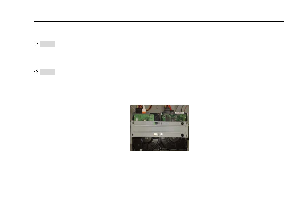
2.1.1 Install Hard Drive
Notice: 1. This series support four SATA hard drives or support three SATA hard drives plus one DVD writer. Please use
the hard drive the manufacturers recommend specially for security and safe field.
2. Please calculate HDD capacity according to the recording setting. Please refer to “Appendix B Calculate
Recording Capacity”.
Step1: Unscrew and Open the top cover
Step2: Connect the power and data cables. Place the HDD onto the bottom case as below.
Fig 2.1 Connect HDD
Step3: Screw the HDD
Note: For the convenience to install, please connect the power and data cables firstly, and then screw to fix.
10
Page 11
Digital Video Recorder User Manual
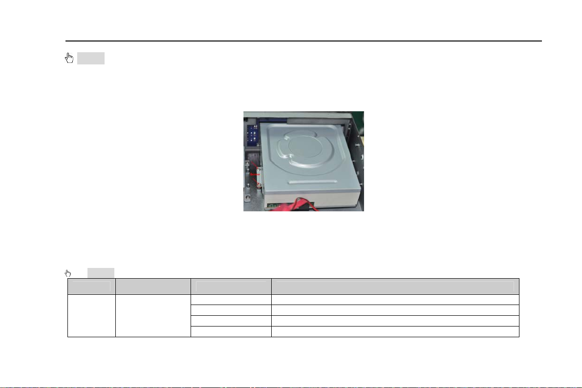
2.1.2 Install DVD Writer
Notice: 1. The writers must be the compatible devices we recommend. Please refer to “Appendix C Compatible
Devices”
2. This device is only for backup
SStep1: Unscrew and Open the top cover
tep2: Connect the power and data cables. Place the DVD writer onto the bottom case as below.
Fig 2.2 Connect the DVD Writer
Step3: Screw the DVD writer.
2.2 Front Panel Descriptions
Notice: The front panel descriptions are only for reference; please make the object as the standard.
Item
1
Type
Work state
indicator
Name Description
Power Power indicator, when connection , the light is blue
HDD When HDD is writing and reading , the light is blue
Net When access to network , the light is blue
Backup When backup files and data, the light is blue
11
Page 12
Digital Video Recorder User Manual
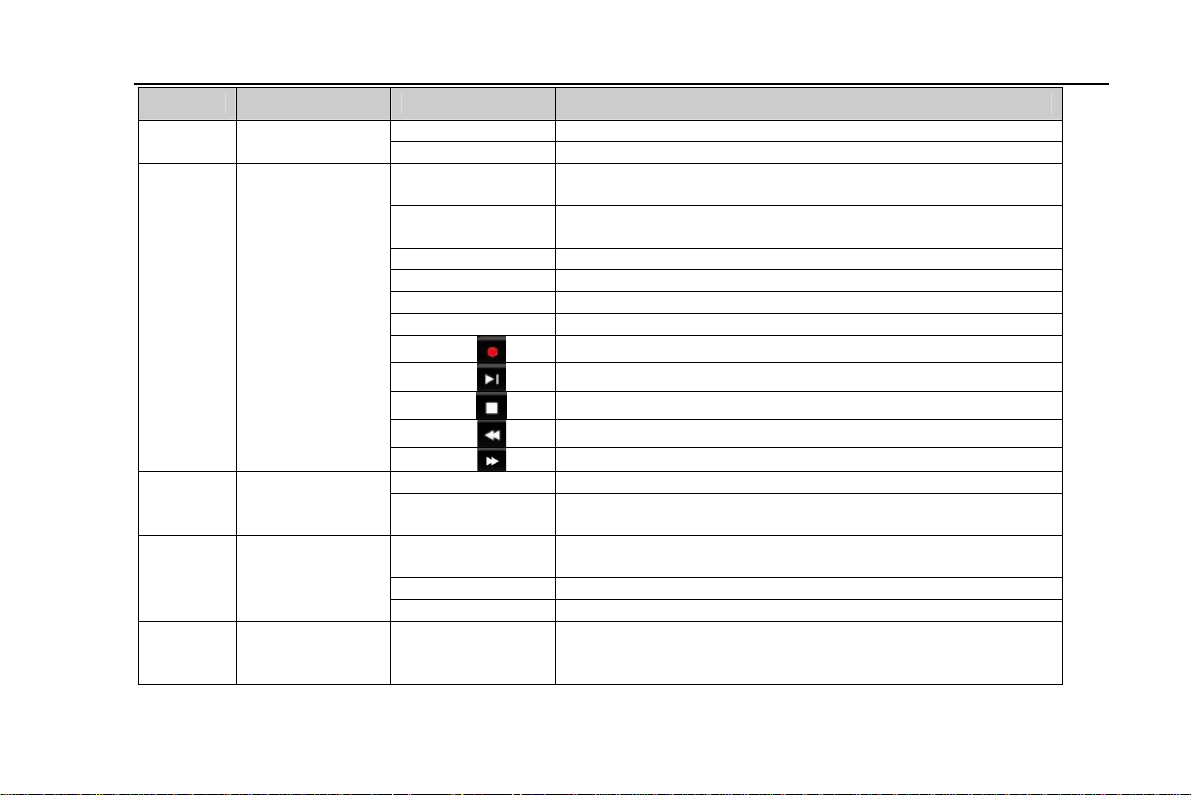
Item Name Description
2
3
4
5
Type
Compound
button
Digital
button
Input button
USB
Play When playing video, the light is blue
REC When recording, the light is blue
AUDIO/+
P.T.Z./ -
MENU Enter menu in live
INFO Check recording data
BACKUP Enter backup mode in live
SEARCH Enter search mode
1-9 Input number 1-9 or choose camera
0/10+
Direction
button
Multi-screen Change screen display mode like1/4/9/16 channel
Enter button Confirm selection
USB port
1. Control voice
2. Increase the value in setup
1. Enter PTZ mode in live
2. Decrease the value in setup
Record manually
Play/Pause
Stop/Esc
Rewind
Fast forward
Input number0, 10 and the above number together with
other digital keys
Change direction to select items
To connect external USB devices like USB flash, USB
HDD for backup or update firmware; or connect to USB
mouse
12
Page 13
Digital Video Recorder User Manual
2.3 Rear Panel Instructions
2.3.1 Rear Panel Interface
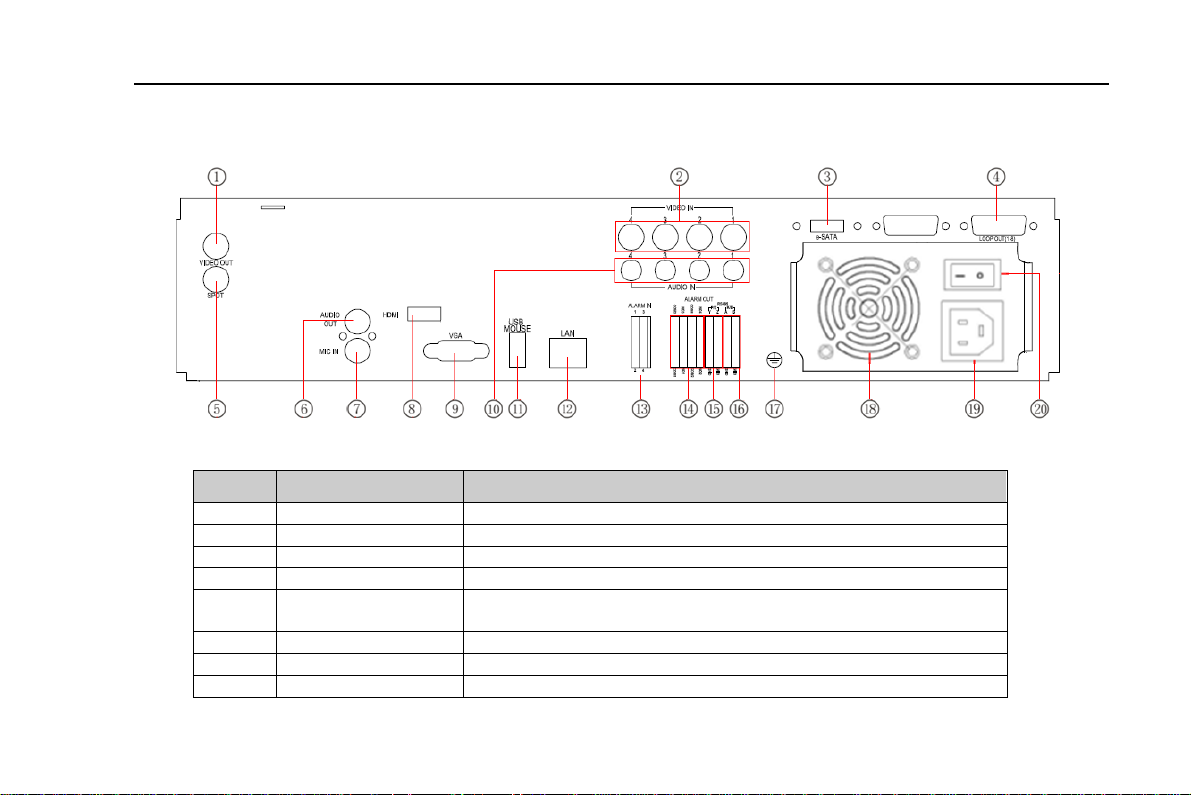
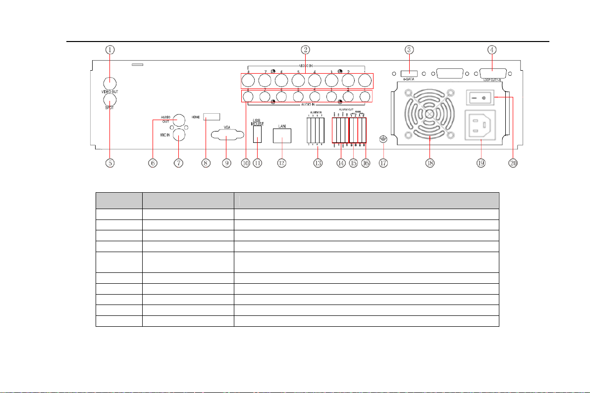
The rear Panel interface for 4-ch is shown as Fig 2.3:
Fig 2.3 Rear Panel for 4-ch
Item Name Description
1 Video out Connect to monitor
2 Video in Video input channels from 1-4
3 E-SATA Connect to HDD for backup
4 LOOP OUT For outputting 1-4ch image independently
5 Spot out
6 Audio out Audio output, connect to the sound box
7 MIC IN Talk
8 HDMI port Connect to high-definition display device
Connect to monitor as an AUX output channel by channel.
Only video display, no menu show
13
Page 14

Digital Video Recorder User Manual
Item Name Description
9 VGA port VGA output, connect to monitor
10 Audio in 4 CH Audio input
11 USB port
12 LAN Network port
13 ALARM IN Connect to external sensor1-4
14 ALARM OUT 4ch relay output. Connect to external alarm.
15 P/Z Connect to speed dome
16 K/B Connect to keyboard
17 GND Grounding
18 FAN For cooling the device
19 POWER INPUT AC 110Vor 110V
20
The rear Panel interface for 8-ch is shown as Fig 2.4:
POWER
SWITCH
To connect external USB devices like USB flash, USB HDD
for backup or update firmware; or connect to USB mouse
Switch on/off
Tab 2.1 Definitions of Front Panel Buttons
14
Page 15
Digital Video Recorder User Manual
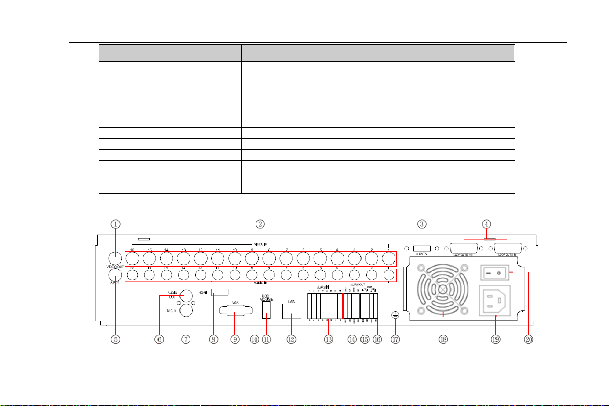
Fig 2.4 Rear Panel for 8-ch
Item Name Description
1 Video out Connect to monitor
2 Video in Video input channels from 1-8
3 E-SATA Connect to HDD for backup
4 LOOP OUT For outputting 1-8ch image independently
5 Spot out
6 Audio out Audio output, connect to the sound box
7 MIC IN Talk
8 HDMI port Connect to high-definition display device
9 VGA port VGA output, connect to monitor
10 Audio in 8 CH Audio input
Connect to monitor as an AUX output channel by channel.
Only video display, no menu show
15
Page 16
Digital Video Recorder User Manual
Item Name Description
11 USB port
12 LAN Network port
13 ALARM IN Connect to external sensor1-8
14 ALARM OUT 4ch relay output. Connect to external alarm.
15 P/Z Connect to speed dome
16 K/B Connect to keyboard
17 GND Grounding
18 FAN For cooling the device
19 POWER INPUT AC 110Vor 110V
20
The rear Panel interface for 16-ch is shown as Fig 2.5:
POWER
SWITCH
Tab 2.2 Definitions of Front Panel Buttons
To connect external USB devices like USB flash, USB HDD
for backup or update firmware; or connect to USB mouse
Switch on/off
Fig 2.5 Rear Panel for 16-ch
16
Page 17

Digital Video Recorder User Manual
Item Name Description
1 Video out Connect to monitor
2 Video in Video input channels from 1-16
3 E-SATA Connect to HDD for backup
4 LOOP OUT For outputting 1-16ch image independently
5 Spot out
6 Audio out Audio output, connect to the sound box
7 MIC IN Talk
8 HDMI port Connect to high-definition display device
9 VGA port VGA output, connect to monitor
10 Audio in 16 CH Audio input
11 USB port
12 LAN Network port
13 ALARM IN Connect to external sensor1-16
14 ALARM OUT 4ch relay output. Connect to external alarm.
15 P/Z Connect to speed dome
16 K/B Connect to keyboard
17 GND Grounding
18 FAN For cooling the device
19 POWER INPUT AC 110Vor 110V
20
POWER
SWITCH
Tab 2.3 Definitions of Rear Panel Buttons
Connect to monitor as an AUX output channel by channel.
Only video display, no menu show
To connect external USB devices like USB flash, USB HDD
for backup or update firmware; or connect to USB mouse
Switch on/off
17
Page 18
Digital Video Recorder User Manual
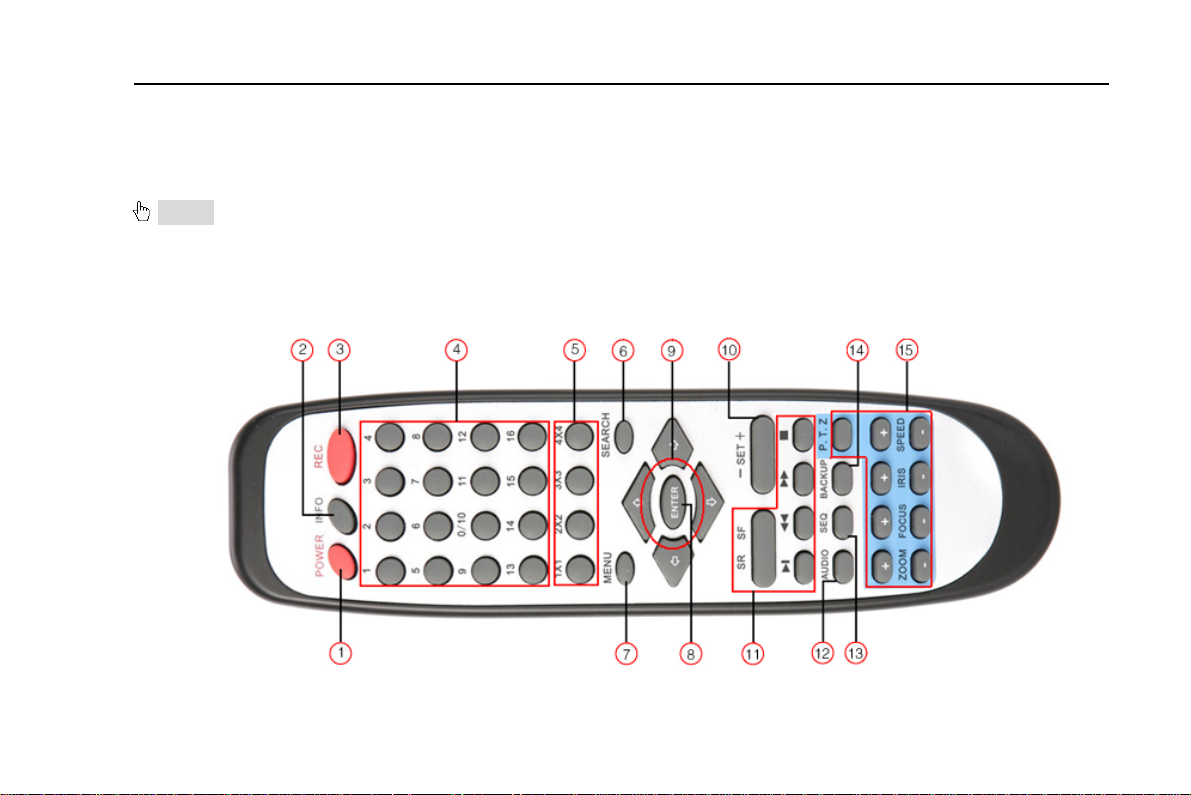
2.4 Remote Controller
It uses two AAA size batteries and works after loading batteries as following:
Step1: Open the battery cover of the Remote Controller
Step2: Place batteries. Please take care the poles (+ and -)
Step3: Replace the battery cover
Notice: Frequently defect checking as following
1. Check batteries poles
2. Check the remaining charge in the batteries
3. Check IR controller sensor is mask
If it still doesn't work, Please change a new remote controller to try, or contact your dealers
The interface of remote controller is shown in Fig2.6 Remote Controller.
Fig 2.6 Remote Controller
18
Page 19

Digital Video Recorder User Manual
Item Name Function
1 Power Button
2 INFOR Button
3 REC Button To record manually
4 Digital Button Input digital or choose camera
5 Multi Screen Button To choose multi screen display mode
6 SEARCH Button To enter search mode
7 MENU Button To enter menu
8 ENTER Button To confirm the choice or setup
9 Direction Button Move cursor in setup or pan/title PTZ
10 +/- Button To increase or decrease the value in setup
11
12 AUDIO Button To enable audio output in live mode
13 Auto Dwell Button To enter auto dwell mode
14 BACKUP Button To enter backup mode
15 PTZ Control Button
Operation processes with remote controller to control multi-DVR
The device ID of the DVR is 0. When use of remote controller to control single DVR, it’s not necessarily to reset the device
ID, user can do operation directly; when control multiple DVR with remote controller, please refer to below steps:
Step1: Activate remote controller to control DVR: enable DVR: turn the IR sensor of the remote controller to the IR receiver
that on the front panel, press the number key 8 twice, then input device ID (Range from: 0-65535; the default device ID is 0.)
with other digital number: 0-9, after that, press ENTER button to confirm.
Playback Control
Button
Soft switch off to stop firmware running. Do it before
power off.
Get information about the DVR like firmware version,
HDD information
To control playback, Fast forward/rewind/stop/single
frame play
To control PTZ camera:
Move camera/ZOOM/FOCUS/IRIS/SPEED control
19
Page 20

Digital Video Recorder User Manual
Step2: User can check the device ID by enter into System configurationÆBasic configurationÆdevice ID. User also can set
other DVRs with the same device ID. For more convenient to operate, we don’t recommend user to set the device ID too
long.
Step3: Cancel controller to control DVR: turn the IR sensor of the remote controller to the IR receiver that on the front panel,
press the number key 8 twice, then input the device ID that needs to be cancelled from controlling, press ENTER button to
confirm. After that, the DVR will not be controlled by remote controller.
2.5 Control with Mouse
2.5.1 Connect Mouse
It supports USB mouse through the ports on the rear panel, please refer to Fig 2.6 Remote Controller.
Notice: If mouse is not detected or doesn't work, check below steps:
1. Make sure the mouse plugs in the USB mouse port not the USB port
2. Change a mouse to try
2.5.2 Use Mouse
The structure of the main menu is shown in Fig 2.6 Remote Controller.
In live:
Double-click left button on one camera to be full screen display. Double-click again to return to the previous screen display.
Click right button to show the control bar at the bottom of the screen as Fig 2.6 Remote Controller. Here are all control and
setup. Click right mouse again to hide the control bar.
In setup:
Click left button to enter. Click right button to cancel setup, or return to the previous.
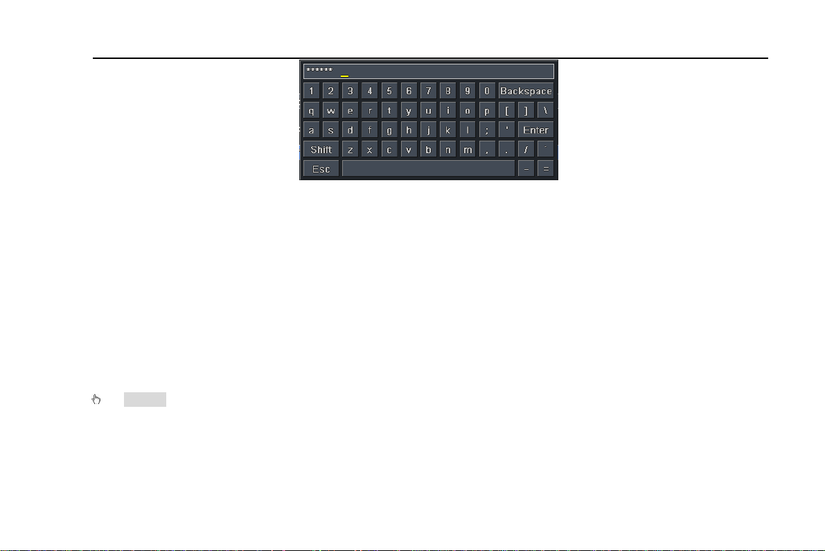
If want to input the value, move cursor to the blank and click. An input window will appear as Fig2.7. It supports digitals,
letters and symbols input.
20
Page 21
Digital Video Recorder User Manual
Fig 2.7 Digital Numbers and Letters Input Window
Users can change some value by the wheel, such as time. Move cursor onto the value, and roll the wheel when the value
blinks.
It supports mouse drag. I.e. Set motion detection area: click customized, hold left button and drag to set motion detection
area. Set schedule: hold left button and drag to set schedule time
In playback:
Click left button to choose the options. Click right button to return to live mode.
In backup:
Click left button to choose the options. Click right button to return to previous picture.
In PTZ control:
Click left button to choose the buttons to control the PTZ. Click right button to return to live.
Notice: Mouse is the default tool in all the operation below unless Exceptional indication.
21
Page 22
Digital Video Recorder User Manual
3 Basic Function Instruction
3.1 Power On/Off
Before you power on the unit, please make sure all the connection is good.
3.1.1 Power on
Step1: connect with the source power; switch on the power button near the power port on the rear panel
Step2: the device will be loaded, and the power indicator will display blue
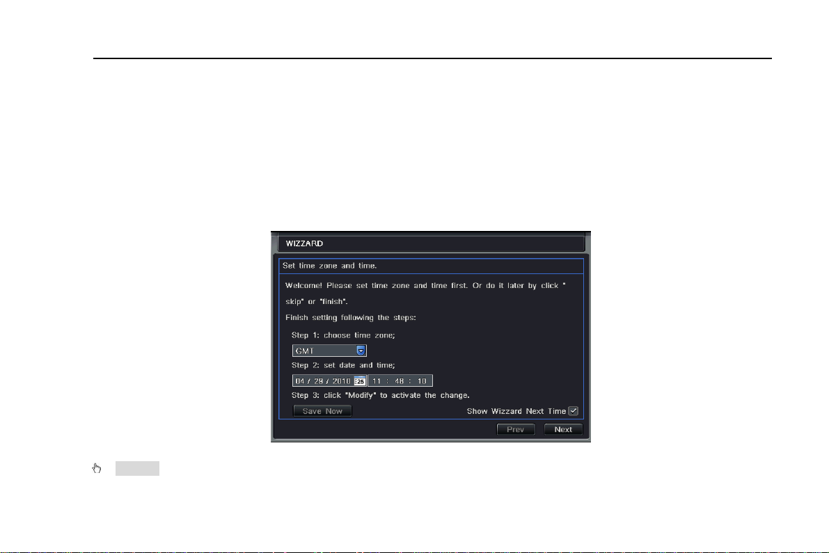
Step3: before start, a WIZZARD dialogue box will be pop-up (refer to below picture) and show some information about time
zone and time setup.
After the device power on, if there is no menu or only has live image display, user can long press ESC button to switch.
Notice: this serial device can only display menu on VGA monitor or BNC monitor at one time, if there is live image
22
Page 23
Digital Video Recorder User Manual
display without menu display, please check up whether other device has menu display firstly, or long press ESC key to
wait for login dialog box to appear. Long press ESC key can switch the output between BNC and VGA.
3.1.2 Power off
User can power off the device by using remote controller、keyboard and mouse.
By remote controller:
Step1: press Power button, the Shut down window will appear, click OK, the unit will power off after a while.
Step2: disconnect the power
By keyboard and mouse:
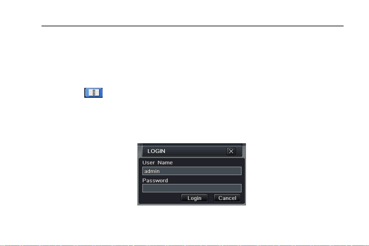
Step1: enter into
Step2: click OK, the unit will power off after a while.
Step3: disconnect the power
3.2 Login
User can login and logout the DVR system. User cannot do any other operations except changing the multi-screen display once logout.
Menu, then select “System Shut Down” icon, the Shut down window will appear
Fig 3-1 Login
23
Page 24
Digital Video Recorder User Manual
Notice: the default user name and password is “admin” and 123456”
The concrete operation steps for change password, add or delete user please refer to Fig 3.7 User management
configuration for more details.
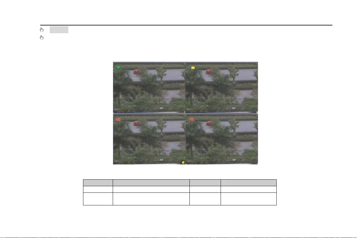
3.3 Live preview
Fig 3-2 live preview interface
The explanation of symbol in the live preview interface:
Symbol Meaning Symbol Meaning
Green Manual record or time record Red Alarm record
Yellow Motion detection record
Figure
icon
Move event
24
Page 25
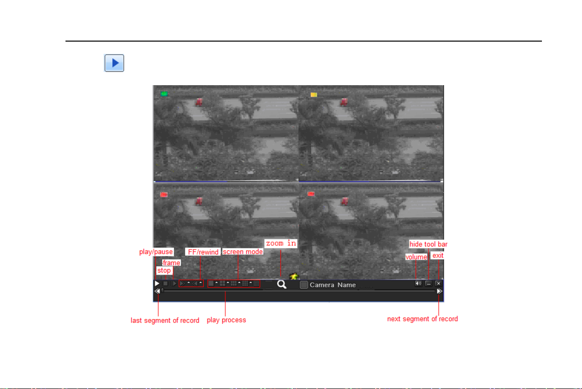
3.3.1 Live playback
Digital Video Recorder User Manual
Click Play
screen.
button to playback the record. Refer to Figure3-3. User can do concrete operation by click the buttons on
Fig 3-3 live playback
25
Page 26
Digital Video Recorder User Manual
4 Main menu setup guide
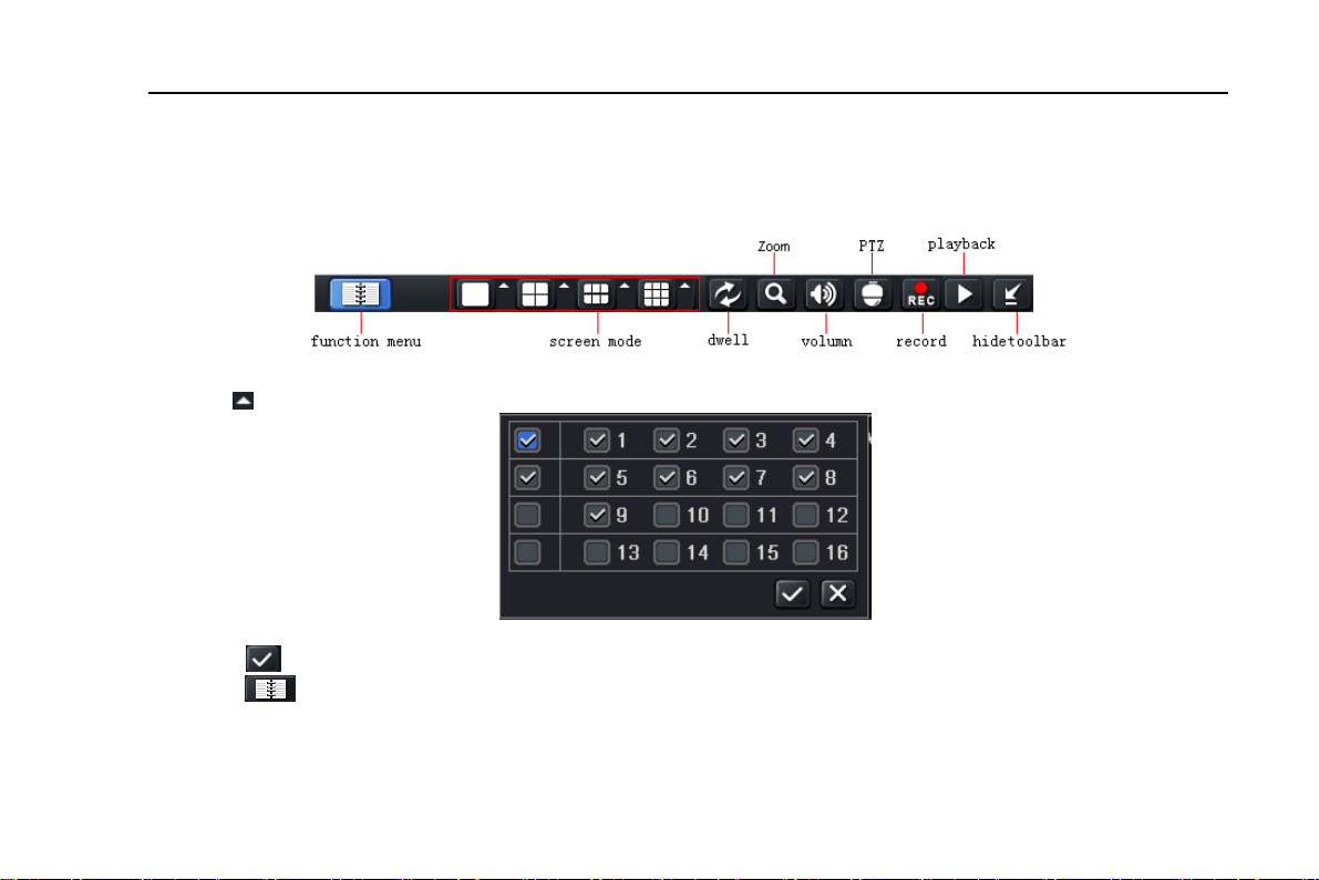
Click right mouse or press ESC button on the front panel, the control bar will display on the bottom of the screen, refer to Fig 4-1:
Fig 4-1 main menu toolbar
Click the
Take 8-channel DVR for example: user can tick off 8 channels form 1-ch to 16-ch at random to display the live pictures.
Then click button to confirm the setting.
Click Menu
controller also can display the main menu.
icon beside the screen display mode, a channel select dialog will appear as below:
button, the interface will pop-up as Fig 4-2; press MENU button on the front panel or operate with remote
26
Page 27
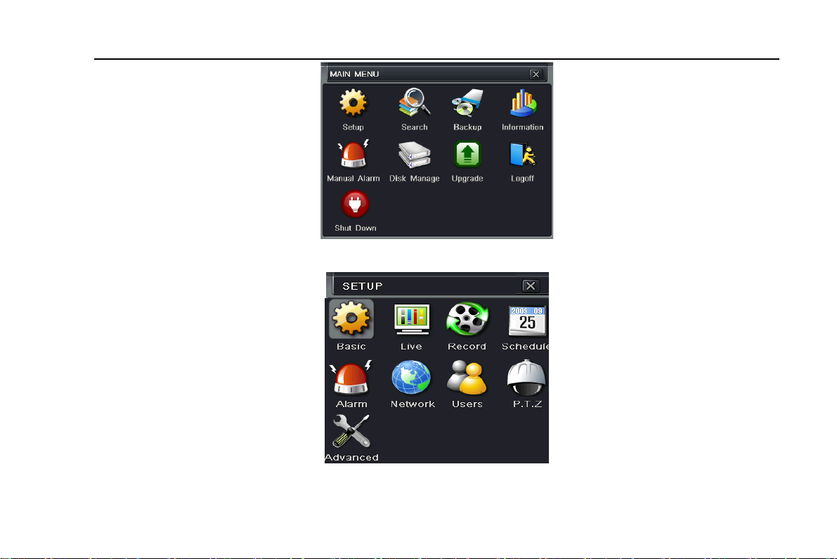
Digital Video Recorder User Manual
Click Setup icon will pop-up the configuration menu:
Fig 4-2 Main Menu
27
Page 28
Digital Video Recorder User Manual
4.1 Basic configuration
Basic configuration includes three sub menus: system、date& time and DST.
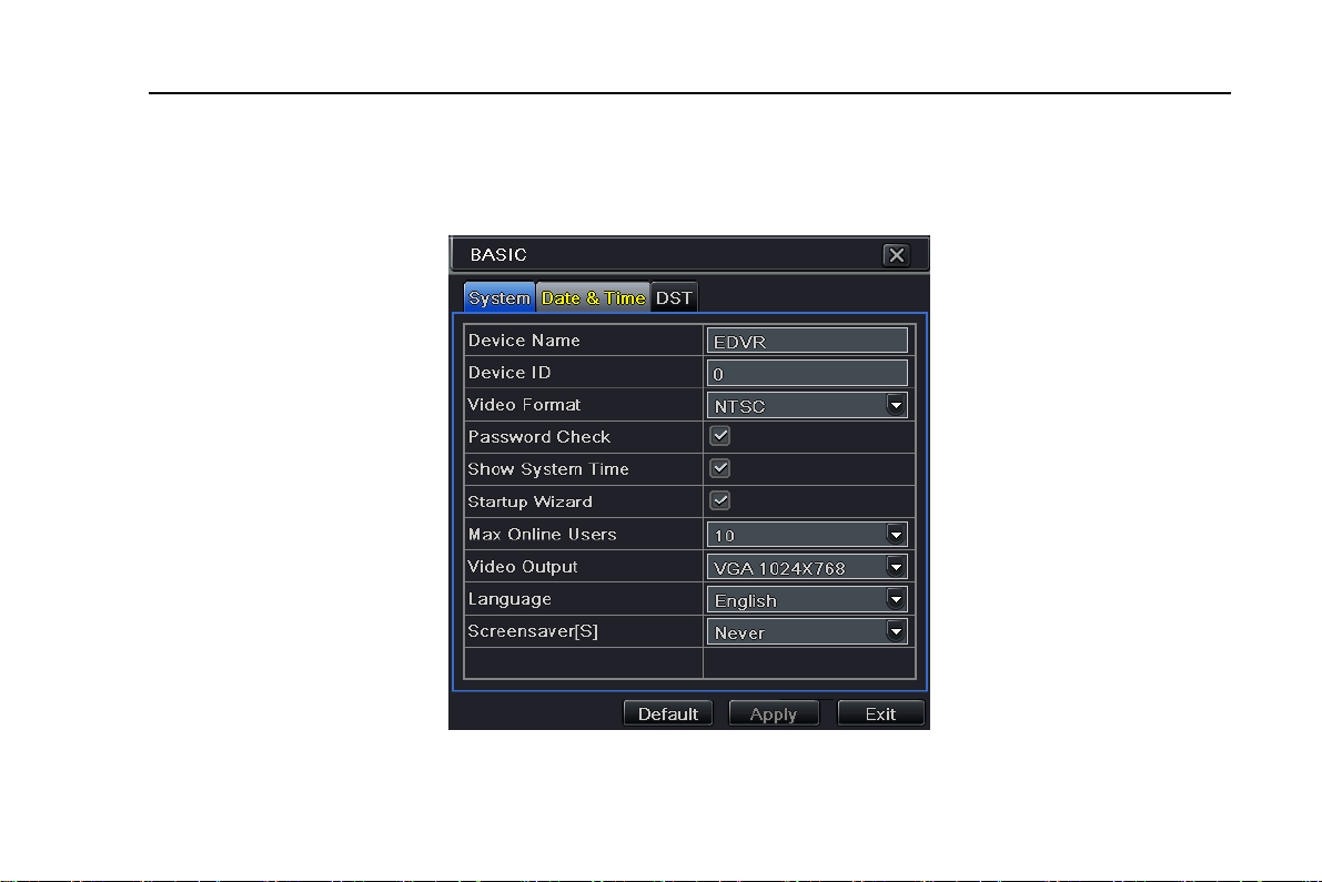
4.1.1 System
Step1: enter into system configurationÆbasic configurationÆsystem; refer to Fig 4-3:
Fig 4-3 basic configuration-basic
28
Page 29

Digital Video Recorder User Manual
Step2: in this interface user can setup the device name, device ID, video format, max network users, VGA resolution and language. The definitions for every parameters display as below:
Device name: the name of the device. It may display on the client end or CMS that help user to recognize the device
remotely.
Video format: two modes: PAL and NTSC. User can select the video format according to that of camera.
Password check: enable this option, user needs to input user name and password can do corresponding operations with
the relevant right in system configuration.
Show time: display time in live.
Show wizard: tick off this item, there will display an opening wizard with time zone and time setup information
Max network uses: set the max user amount of network connection
VGA resolution: the resolution of live display interface, range from: VGA800*600、VGA1024*768、VGA1280*1024and
CVBS
Note: When switch between VGA and CVBS will change the menu output mode, please connect to relevant monitor.
Language: setup the menu language.
Note: after changed the language and video output, the device needs to login again.
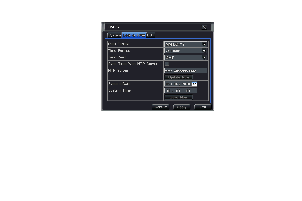
4.1.2 Time & date
Step1: enter into system configurationÆbasic configurationÆtime & date; refer to Fig 4-4:
29
Page 30
Digital Video Recorder User Manual
Fig 4-4 basic configuration-time & date
Step2: set the date format, time format, time zone in this interface; tick off “sync time with NTP server” to refresh NTP
server date; user also can adjust system date manually
Step3: click “default” button to resort default setting; click “apply” button to save the setting; click “exit” button to exit current
interface.
4.1.3 DST
Step1: enter into system configurationÆbasic configurationÆDST; refer to Fig 4-5:
30
Page 31

Digital Video Recorder User Manual
Fig 4-5 basic configuration-DST
Step2: in this interface, enable daylight saving time, time offset, mode, start & end month/week/date, etc.
Step3: click “default” button to resort default setting; click “apply” button to save the setting; click “exit” button to exit current
interface.
4.2 Live configuration
Live configuration includes four submenus: live, main monitor, SPOT and mask.
4.2.1 Live
In this interface, user can setup camera name, adjust colors: brightness, hue, saturation and contrast.
31
Page 32

Digital Video Recorder User Manual
Step1: enter into system configurationÆlive configurationÆlive; refer to Fig 4-6:
Fig 4-6 live configurationÆlive
Step2: tick off camera name; click “setting” button, a window will pop-up as Fig 4-7:
32
Page 33

Digital Video Recorder User Manual
Fig 4-7 live-color adjustment
Step3: in this interface, user can adjust brightness,
default setting, click “OK” button to save the setting.
Step4: user can setup all channels with same parameters, tick off “all”, then do relevant setup.
Step5: click
interface.
4.2.2 Main monitor
Step1: enter into system configurationÆlive configurationÆmain monitor; refer to Fig 4-8:
Step2: select split mode: 1×1、2×2、2×3、3×3、4×4 and channel
Step3: dwell time: the time interval for a certain dwell picture display sw ing to next dwell picture display
Step4: selected the it mode, then setup current picture group. Click button to setup the previous channel groups of
dwell picture, click button to set the latter channel groups of dwell picture.
Step5: click “default” button to resort default setting; click “apply” button to save the setting; click “exit” button to exit current
“default” button to resort default setting; click “apply” button to save the setting; click “exit” button to exit current
Fig 4-8 live configuration-main monitor
spl
hue, saturation and contrast in live; click “default” button to resort
itch
33
Page 34

Digital Video Recorder User Manual
interface.
4.2.3 SPOT
Step1: enter into system configurationÆlive configurationÆSPOT; refer to Fig 4-9:
Fig 4-9 live configuration-SPOT
Step2: select split mode: 1×1and channel
Step3: dwell time: the time interval for a certain dwell picture display sw ing to next dwell picture display
Step4: selected the it mode, then setup current picture group. Click button to setup the previous channel groups of
dwell picture, click button to set the latter channel groups of dwell picture.
Step5: click “default” button to resort default setting; click “apply” button to save the setting; click “exit” button to exit current
in
terface
4.2.4 Mask
U
ser can setup private mask area on the live image picture, max threes areas.
spl
itch
34
Page 35

Digital Video Recorder User Manual
Fig 4-10 live configuration-mask
Setup mask area: click Setting button, enter into live image to press left mouse and drag mouse to set mask area, refer to
below picture. Click Apply button to save the setting.
Delete mask area: select a certain mask area, click left mouse to delete that mask area, click Apply button to save the
setting.
35
Page 36

Digital Video Recorder User Manual
Setup mask area
Live image mask area
4.3 Record configuration
Record configuration includes five sub menus: enable, record bit rate, time, recycle record and stamp.
4.3.1 Enable
Step1: enter into system configurationÆrecord configurationÆenable; refer to Fig 4-11:
36
Page 37

Digital Video Recorder User Manual
Fig 4-11 record configuration-enable
Step2: tick off record, audio and record time
Step3: user can setup all channels with same parameters, tick off “all”, then to do relevant setup.
Step4: click “default” button to resort default setting; click “apply” button to save the setting; click “exit” button to exit current
interface.
Definitions and descriptions of Record:
Parameter Meaning
Record Record switch of every channels
Audio Enable live record audio
37
Page 38

Digital Video Recorder User Manual
4.3.2 Record stream
Step1: enter into system configurationÆrecord configurationÆrecord bit rate; refer to Fig 4-12:
Fig 4-12 record configuration-record bit rate
Step2: setup rate, resolution, quality, encode and max bit stream
Step3: user can setup all channels with same parameters, tick off “All”, then to do relevant setup.
Step4: click “default” button to resort default setting; click “apply” button to save the setting; click “exit” button to exit current
interface.
Note: if the rate value set is over high the maximum resources of the device, the value will be adjusted
automatically.
Definitions and descriptions of Record stream:
38
Page 39

Digital Video Recorder User Manual
Parameter Meaning
Rate
Resolution Support CIF and D1
Quality The quality of recorded images. The higher the value is, the clearer the recorded
Encode VBR and CBR
Max bit stream
4.3.3 Time
Step1: enter into system configurationÆrecord configurationÆ time; refer to Fig 4-13:
Range from: 1-30(NTSC)1-25(PAL)
image is. Six options: lowest, lower, low, medium, higher and highest.
Range from: 64 Kbps、128 Kbps、256 Kbps、512 Kbps、768 Kbps、1Mbps、2 Mbps
Fig 4-13 record configuration-time
39
Page 40

Digital Video Recorder User Manual
Pre-alarm record time: the record time before event happen i.e. record time before motion detection or sensor alarm is
triggered.
Post-alarm record: set the post recording time after the alarm is finished, five options: 10s、15s、20s、30s and 60s.
Expire time: the hold time of saved records. If the set date is overdue, the record files will be deleted automatically.
Step2: user can setup all channels with same parameters, tick off “all”, then to do relevant setup.
Step3: click “default” button to resort default setting; click “apply” button to save the setting; click “exit” button to exit current
interface.
4.3.4 Stamp Stamp:User can overlap the channel name and time stamp on video.
Step1: enter into system configurationÆ record configurationÆ stamp; refer to Fig 4-14:
Fig 4-14 record configuration-stamp
Step2: tick off camera name, time stamp; click Set button, user can use cursor to drag the camera name and time stamp in
40
Page 41

Digital Video Recorder User Manual
random positions, refer to below Figures:
Before drag after drag
Step3: user can setup all channels with same parameters, tick off “all”, then to do relevant setup.
Step4: click “default” button to resort default setting; click “apply” button to save the setting; click “exit” button to exit current
interface.
4.3.5 Recycle record
Step1: enter into system configurationÆrecord configurationÆrecycle record;
Step2: tick off recycle record, the recycle record function will enable, it will cover the earlier recorded files and keep
recoding when HDD is full; if disenable this function, it will stop recording when HDD is full.
Step3: click “default” button to resort default setting; click “apply” button to save the setting; click “exit” button to exit current
interface.
4.4 Schedule configuration
Schedule configuration includes three sub menus: schedule, motion and alarm.
41
Page 42

Digital Video Recorder User Manual
4.4.1 Schedule
The volume means the seven days of a week from Monday to Sunday, the row means 24 hours of a day. Click the grid to
do relevant setup. Blue means checked area, gray means unchecked area.
Step1: enter into system configurationÆschedule configurationÆschedule; refer to Fig 4-15:
Fig 4-15 schedule configuration-schedule
Step2: select channel, double-click and a dialog box will pop-up as Fig 4-16, user can edit week schedule:
42
Page 43

Digital Video Recorder User Manual
Fig 4-16 schedule-week schedule
① te” button to delete the selected schedule;
Click “add” button to add a certain day schedule; click “dele
Copy: user can copy the specify schedule to other dates.
Click “OK” button to save the setting, click “Exit” button to exit current interface.
② User can a
“Copy” button.
Step3: click
in
terface.
4.4.2 Motion
Step1: enter into system configurationÆschedule configurationÆmotion; refer to Fig 4-17:
Step2: the setup steps of motion are familiar with schedule; user can refer to 4.4.1 Schedule for details.
Note: the default schedule of motion detection is full-selected, that is, th e color of schedule setting interface is
pply the schedule setting of certain channel to other or all channels, just only select channel and click
“default” button to resort default setting; click “apply” button to save the setting; click “exit” button to exit current
Fig 4-17 schedule configuration-motion
43
Page 44

Digital Video Recorder User Manual
blue.
4.4.3 Sensor
Step1: enter into system configurationÆschedule configurationÆalarm; refer to Fig 4-18:
Step2: the setup steps of alarm are familiar with schedule; user can refer to 4.4.1 Schedule for details.
ote: the default schedule of sensor is full-selected, that is, the color of schedule setting interface is blu e.
N
Fig 4-18 schedule configuration-sensor
4.5 Alarm configuration
larm configuration includes five sub menus: sensor, motion, video loss, other alarm and alarm out.
A
44
Page 45

Digital Video Recorder User Manual
4.5.1 Se
Sensor includes three sub menus: basic, alarm handling and schedule.
① Basic
Step1: enter into system configurationÆalarm configurationÆsensorÆbasic; refer to Fig 4-19:
Step2: enable sensor alarm, set the alarm type according to triggered alarm type. Two option: NO and NC.
Step3: user can setup all channels with same parameters, tick off “all”, then to do relevant setup.
S
interface.
② Alarm handling
Step1: enter into system configurationÆalarm configurationÆsensorÆalarm handling; refer to Fig 4-20:
nsor
Fig 4-19 alarm configuration-sensor-basic
tep4: click “default” button to resort default setting; click “apply” button to save the setting; click “exit” button to exit current
45
Page 46

Digital Video Recorder User Manual
Fig 4-20 alarm configuration-sensor-alarm handling
Step2: select hold time, click Trigger button, and a dialog box will pop-up as Fig 4-21:
Fig 4-21 alarm handling-trigger
Step3: tick off Buzzer, there will be triggered buzzer alarm out;
Full screen alarm: when triggered alarm, there will pop up full screen alarm;
46
Page 47

Digital Video Recorder User Manual
Email: tick of this function, when an alarm trigged, a notification email will be sent to user’s designed email box including
trigger events, time, snap pictures, device name, ID camera name etc.
To alarm out: tick off the channel, there will be triggered alarm out in the designated channel. Click OK button to save the
setting; click Exit button to exit the current interface.
To record: tick off recoding channels, it will record the camera when alarm triggered. Click OK button to save the setting;
click Exit button to exit the current interface.
To P.T.Z: set linked preset and cruise for alarm. User can select any channel and multi channels as linked channels. Click
OK button to save the setting; click Exit button to exit the current interface.
Step4: user can setup all channels with same parameters, tick off “all”, then to do relevant setup.
Step5: click “default” button to resort default setting; click “apply” button to save the setting; click “exit” button to exit current
interface.
③ Schedule
Step1: enter into system configurationÆalarm configurationÆsensorÆschedule; refer to Fig 4-22:
Fig 4-22 sensor-schedule
47
Page 48

Digital Video Recorder User Manual
Step2: the setup steps of sensor schedule are familiar with schedule; user can refer to 4.4.1 Schedule for details.
Note: the default schedule of sensor is full-selected, that is, the color of schedule setting interface is blue.
4.5.2 Motion
Motion includes two sub menus: motion and schedule.
① Motion
Step1: enter into system configurationÆalarm configurationÆmotion; refer to Fig 4-23:
Fig 4-23 alarm configuration-motion
Step2: enable motion alarm, set alarm hold time which means time interval between two adjacent detective motions. If
there is other motion detected during the interval period which is considered continuous movement; otherwise, it will be
considered that those two adjacent detective motions are two different motion events. Click Trigger button, a dialog box will
pop-up:
48
Page 49

Digital Video Recorder User Manual
Step3: the setup steps of motion trigger are familiar with alarm handling; user can refer to Chapter 4.5.1 Sensor Æalarm
handling for more details.
Step4: click Area button, a dialog box will pop-up as Fig 4-24:
Fig 4-24 motion-area
Step5: in the Area interface, user can drag slide bar to set the sensitivity value (1-8), the default value is 4. The higher the
value is the higher sensitivity you get. Due to the sensitivity is influenced by color and time (day or night), user can adjust
its value according to the practical conditions; click
set detection area will be cleared; click
icon, user can test whether the sensitivity value and motion area are suitable
icon, set the whole area as detection area; click icon, the
accordingly(refer to following picture); Click
icon, to save the setting; click icon, exit current interface.
49
Page 50

Digital Video Recorder User Manual
Note: when user drag mouse to set motion detection area, they ha ve to click
area firstly, and then make the operation.
Step6: user can setup all channels with same parameters, tick off “all”, then to do relevant setup.
Step7: click “default” button to resort default setting; click “apply” button to save the setting; click “exit” button to exit current
interface.
② Schedule
Step1: enter into system configurationÆalarm configurationÆschedule; refer to Fig 4-25:
Fig3-25 alarm configuration-schedule
Step2: the setup steps of alarm schedule are familiar with schedule; user can refer to 4.4.1 Schedule for details.
icon to clear all set detection
50
Page 51

Digital Video Recorder User Manual
4.5.3 Video loss
Step1: enter into system configurationÆalarm configurationÆvideo loss; refer to Fig 4-26:
Fig 4-26 alarm configuration-video loss
Step2: the setup steps of video loss trigger are familiar with alarm handling; user can refer to Chapter 4.5.1 Sensor Æalarm
handling for more details.
Step3: user can setup all channels with same parameters, tick off “all”, then to do relevant setup.
Step4: click “default” button to resort default setting; click “apply” button to save the setting; click “exit” button to exit current
interface.
51
Page 52

Digital Video Recorder User Manual
4.5.4 Other alarm
Step1: enter into system configurationÆother alarm; refer to Fig 4-27:
Fig4-27 other alarm
Step 2: Disk Full: If the disk is full, the device will auto send an email to users designated mailbox to notify the conflict
details.
IP conflict: if there is an IP address conflict within the same network, the device will auto send an email to users
designated mailbox to notify the conflict details.
Disconnect: if the disconnect happen, the device will auto send disconnection information to users designated
mailbox.
Step3: the setup steps of Buzzer, Email, To Alarm Out are familiar with alarm handling; user can refer to Chapter 4.5.1
Sensor Æalarm handling for more details.
Step 4: select a hard disk in the pull down list box, when the disk capacity is lower than that value, there will appear some
text information on the lower right of the live image.
Step 5: click “default” button to resort default setting; click “apply” button to save the setting; click “exit” button to exit
current interface.
52
Page 53

Digital Video Recorder User Manual
4.5.5 Alarm out
Alarm out includes three sub menus: alarm out, schedule and buzzer
① Alarm out
Step1: enter into system configurationÆalarm out; refer to Fig 4-28:
Fig 4-28 system configuration-alarm out
Step2: in this interface, set relay alarm out name, select hold time which means the interval time between the two adjacent
alarms.
Step3: user can setup all channels with same parameters, tick off “all”, then to do relevant setup.
Step4: click “default” button to resort default setting; click “apply” button to save the setting; click “exit” button to exit current
interface.
② Schedule
Step1: enter into system configurationÆschedule;
Step2: the setup steps of alarm out schedule are familiar with schedule; user can refer to 4.4.1 Schedule for details.
Note: the default schedule of motion detection is full-selected, that is, th e color of schedule setting interface is
blue.
③ Buzzer
Step1: enter into system configurationÆbuzzer;
Step2: tick off Buzzer, set buzzer alarm hold time
53
Page 54

Digital Video Recorder User Manual
4.6 Network configuration
Network configuration includes two submenus: network and network stream.
4.6.1 Network
Step1: enter into system configurationÆnetwork configurationÆnetwork; refer to Fig4-29:
Fig 4-29 network configuration-network
Step2: HTTP port: the default value is 80. If the value changed, user needs to add the port number when typing IP address
54
Page 55

Digital Video Recorder User Manual
in IE address blank .i.e. set HTTP port to 82, IP address: http://192.168.0.25, user needs to input that address:
http://192.168.0.25:82 into IE browser.
Server port: communication port
Step3: Tick off the "Obtain IP address automatically", the device will distribute IP address, subnet mask, gateway IP and
DDNS service;
Step4: enable PPPOE, user can directly connect the DVR to internet via ADSL, then input the user name and password;
click TEST button to test the effectively of relevant information.
Definitions and descriptions of network:
Parameter Meaning
FPS Range from: 1-25
Resolution Support CIF and D1
Quality The quality of the clients’ image. The higher the value is, the clearer the record
mage. Six options: lowest, lower, low, medium, higher and highest. i
Encode VBR and CBR
Max bit rate
4.6.2 Sub stream
Step1: enter into system configurationÆnetwork configurationÆsub stream; refer to Fig 4-30:
Range from: 64 Kbps、128 Kbps、256 Kbps、512 Kbps、768 Kbps、1Mbps、2 Mbps
55
Page 56

Digital Video Recorder User Manual
Fig 4-30 network configuration-sub stream
Step2: select fps, resolution, quality, encode and max bit rate
Step3: user can setup all channels with same parameters, tick off “all”, then to do relevant setup.
Step4: click “default” button to resort default setting; click “apply” button to save the setting; click “exit” button to exit current
interface.
Note: After selecting Resolution and Fps, the rest fps will be shown.
Definitions and descriptions of Sub stream:
Parameter Meaning FPS Resolution
Range from: 1-25
Support CIF and D1
56
Page 57
Digital Video Recorder User Manual
Quality
Encode
Max bit rate
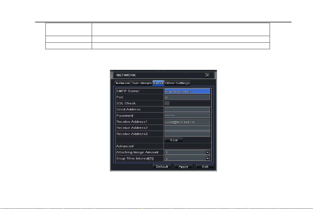
4.6.3 Email
Step1: enter into system configurationÆnetwork configurationÆemail; refer to Fig 4-31:
SMTP Server/Port: the name and port number of SMTP server.
The quality of the clients’ image. The higher the value is, the clearer the record
i
mage. Six options: lowest, lower, low, medium, higher and highest.
VBR and CBR
Range from: 64 Kbps、128 Kbps、256 Kbps、512 Kbps、768 Kbps、1Mbps、2 Mbps
Fig 4-31 network configuration-email
57
Page 58

Digital Video Recorder User Manual
Tick off “This server requires a secure connection (SSL)”; user can setup mail servers (such as Gmail) according to actual
needs,
Send address/password: sender’s email address/password
Receive address: receiver’s email address. Here user can add at least three mail addresses.
Click TEST button to test the valid of the mailbox.
Attaching image amount: user can attach at most three images at one time.
Snap Time Interval(s): User can select snap time interval.
4.6.4 Other settings
Step1: enable DDNS server: user needs to input user name, password and host domain name of the registered website,
click TEST to test the effectively of relevant information.
Fig 4-32 network configuration-other settings
STEP2: click “default” button to resort default setting; click “apply” button to save the setting; click “exit” button to exit
58
Page 59

Digital Video Recorder User Manual
current interface.
Note: The domain name server that selected by user is a banding domain name of DVR. User should logon the
website which provided by the server supplier to register a user name and password firstly, and then apply a
domain name on line for the server. After the successful apply, user can access the server from the IE client by
inputting that domain name.
1. Domain name Registration (Take www.dyndns.com for example)
Note: Users can self-define the hostname, username and password.
Input www.dyndns.com in the IE address bar, user can access the domain name registration interface. Click “Sign up Free”
and then select the first picture, click “Sign up” to register. For example: Hostname is “abc.dyndns.tv. The picture is shown
as follows:
After user fill in the blank, click “Add to cart”, Dynamic DNS Hosts dialog box will be displayed.
59
Page 60

Digital Video Recorder User Manual
Then create user account. For example, the username is “bcd”, password is “123456”.
Click” Create Account” button to create user account.
2. DVR Setting
(1) Domain name
According to the domain name registration of “DDNS”,the domain name for DVR is “www. abc.dyndns.tv”
(2) Username and password
According to the above registration, username is “bcd”.
According to the above registration, password is “123456”
3. Application
Connect DVR to the Network Client.
① Enter into Basic configuration, tick off DDNS, select “Dyndns” at the DDNS Sever pull down list box and input user
name and password.
② Enter into configuration interface of the router, map the server port and IP address. Click Save button to save the
setting
③ Login IE browser and input registered domain name “www.abc.dyndns.tv”, connect to DVR client.
Note: If the value changed, user needs to add the port number when typing IP address in IE address blank .i.e. set
60
Page 61

Digital Video Recorder User Manual
HTTP port to 82, IP address: http://192.168.0.25, user needs to input that address: http://192.168.0.25:82 into IE
browser.
Definitions and descriptions of network configuration:
DDNS server
DDNS server Website provided by dynamic domain name supplier. The
optional: www.dns2p.net , www.meibu.com ,
www.dyndns.comandwww.no-ip.com
User name User name for log in the website of domain name supplier
Password Password for log in the website of domain name supplier
Host domain The domain name user registered at the supplier’s website.
Update interval The interval time of upgrading DVR IP address
4.7 User management configuration
Step1: enter into system configurationÆuser management configuration; refer to Fig 4-33:
Fig 4-33 user management configuration
Step2: click Add button, a dialog box will pop-up as Fig 4-34:
61
Page 62

Digital Video Recorder User Manual
Fig 4-34 add-general
① General: Input user name, password; select user type: normal and advance, input the MAC address of the PC; click
OK button, this user will be added into the user list box; click Exit button to exit the current interface.
Note: when the default value of binding PC MAC address is 0, the user is not bind with the specify computer; the,
the user can log in DVR on the binding computer after set the specific binding MAC address.
② Authority:
Step1: enter into Add userÆauthority; refer to Fig 4-35:
62
Page 63

Digital Video Recorder User Manual
Fig 4-35 add user-authority
Step2: In the authority interface, assign the definite operation right for that user.
Step3: in the user management interface, click Setup button to modify user name, user type and binding PC MAC address.
Step4: select the user that user wants to delete in the user list box, then click Delete button to delete this user.
Step5: click Change password button to modify the password; click Exit button to exit the current interface.
4.8 P.T.Z configuration
P.T.Z configuration includes two submenus: serial port and advance
① Serial port
Step1: enter into system configurationÆP.T.Z configurationÆserial port; refer to Fig 4-36:
63
Page 64

Digital Video Recorder User Manual
Fig 4-36 P.T.Z configuration-serial port
Step2: tick off Enable, setup the value of address, baud rate and protocol according to the settings of the speed dome.
Step3: user can setup all channels with same parameters, tick off “all”, then to do relevant setup.
Step4: click “default” button to resort default setting; click “apply” button to save the setting; click “exit” button to exit current
interface.
Definitions and descriptions of serial port:
Parameter Meaning
Address The address of the PTZ device
Baud rate
Baud rate of the PTZ device. Range form: 110、300、600、1200、2400、
64
Page 65

Digital Video Recorder User Manual
② Advance
Step1: enter into system configurationÆ P.T.Z configurationÆadvance; refer to Fig 4-37:
Step2: in the Advance interface, click preset “Setting” button, a dialog box will pop-up as Fig 4-38:
Protocol
4800、9600、19200、34800、57600、115200、230400、460800、21600.
Communication protocol of the PTZ device. Range from: NULL 、
PELCOP、PELCOD 、LILIN、MINKING、NEON、STAR、VIDO、DSCP、
VISCA、SAMSUNG、RM110、HY
Fig 4-37 P.T.Z configuration-advance
65
Page 66

Digital Video Recorder User Manual
Fig 4-38 advance-preset setting
a. in the preset set interface, click Setting button, a dialog will pop-up as Fig 4-39:
Fig4-39 preset set-setting
b. user can control the dome rotates up, up left, down, right down, left , left down, right and up right and stop rotating; adjust
the rotate speed and the value of zoom, focus and iris of the dome;
c. select the serial number of the preset point, set the preset name. Click Save button to save the settings, click
to hide the tool bar, right-key can remerge it; click icon to exit the current interface.
d. in the preset interface, click OK button to save the setting; click Exit button to exit current interface.
icon
66
Page 67

Digital Video Recorder User Manual
Step3: in the Advance interface, click cruise “Setting” button, a dialog box will pop-up as Fig 4-40:
Fig 4-40 cruise set
a. click Add button to add cruise line in the list box (max 8 cruise line can be added); select a cruise line, click Setup button,
a dialog box will pop-up as Fig 4-41:
Fig 4-41 cruise set-modify cruise line
67
Page 68

Digital Video Recorder User Manual
b. click Add icon
preset point; click Modify icon to modify the setting of a preset point. User can click those icons to
adjust the position of preset point. Click Preview button to preview the cruise line, click OK button to save the setting, click
Exit button to exit current interface.
c. select a preset point in the cruise line list box, click Delete button to delete that cruise line; click Clear all button to clear
all cruise line from the list box; click OK button to save the setting; click Exit button to exit current interface.
Step4: in the Advance interface, click track “Set” button, a dialog box will pop-up as Fig 4-42:
a. user can control the dome rotates up, up left, down, right down, left, left down, right and up right and stop rotating; adjust
the rotate speed and the value of zoom, focus and iris of the dome; click Start Record button to record the move track of
PTZ, click this button again can stop record; click Start track button to play recorded track, click this button again can stop
play.
b. click
Step5: in the Advance interface, click “default” button to resort default setting; click “apply” button to save the setting; click
“exit” button to exit current interface.
4.9 Advanced
Advanced configuration includes two submenus: reset and import/export.
icon to hide the tool bar, right-key can remerge it; click icon to exit the current interface.
to set the speed and time of preset point; select a preset point, click Delete icon to delete that
Fig 4-42 track set
68
Page 69

Digital Video Recorder User Manual
4.9.1 Reset
Reset all settings the device will reboot.
4.9.2 Import/Export
Fig 4-43 Import/Export
User can export the data files into mobile storage devices as backup function, and then import specified data files from
mobile storage device to DVR.
69
Page 70

Digital Video Recorder User Manual
5 Record search & playback and backup
Search configuration includes three submenus: time search, event search and file management.
5.1 Time search
Step1: enter into Search configurationÆtime search; refer to Fig 5-1:
Fig 5-1 Search configuration-time search
Step2: select channel, screen display mode, the highlight date in the calendar means have record data
Step3: select a date, press Search button, click the time grid to set the play start time or input play record time manually.
The selected time match the blue grid.
Note: the vertical column means hours, horizontal column means channels.
Step4: click Play
button to playback record; click the relevant buttons on the screen to do operation:
70
Page 71

Digital Video Recorder User Manual
Playback buttons
Note: when the monitor resolution is VGA800*600, the time search interface will appear a hide button, click this
button, the whole interface can be expanded.
5.2 Event search
Step1: enter into Search configurationÆevent search; refer to Fig 5-2:
Fig 5-2 Search configuration-event search
Step2: click Search button, the searched event information will displayed in the event list box, user can select date, channel,
71
Page 72

Digital Video Recorder User Manual
tick off Motion, Sensor or All accordingly.
Step3: double check a certain record file to playback.
Note: when the monitor resolution is VGA800*600, the event search interface will appear a hide button, click this
button, the whole interface can be expanded.
5.3 File management
Step1: enter into Search configurationÆfile management; refer to Fig 5-3:
Fig 5-3 Search configuration-file management
Step2: click Search button, the searched files will be displayed in the file list box, user can select date, channels
accordingly.
① Lock: checked a file, click Lock button to lock this file, after that, that file will not be deleted or covered.
② Unlock: checked a locked file, click Lock button to unlock this file
72
Page 73

Digital Video Recorder User Manual
③ Delete: checked an unlocked file, click Delete button to delete this file.
Step3: tick off “All” button; user can lock/unlock or delete all files in the file management column.
Step4: double click an unlocked item to playback.
Note: when the monitor resolution is VGA800*600, the file management interface will appear a hide button, click
this button, the whole interface can be expanded.
5.4 Backup
This unit supports backup by built-in SATA DVD Writer with USB Flash, through the USB port on the front panel. User also
can make backup by IE browser via internet. Refer to 7.3.2 Remote backup.
Step1: enter into backup configuration; refer to Fig 5-4:
Fig 5-4 backup configuration
Step2: set the start & end time, select channels, click Search button, the searched data will be displayed in the data backup
73
Page 74

Digital Video Recorder User Manual
list box
Step3: checked a data file or tick off “All” to select all data files , click Backup button, a dialog box will pop-up as Fig 5-5:
Fig 5-5 backup information
Step4: in the backup information interface, user can check the relevant information of backup files, storage type, save file
type, etc. click Start button to starting backup.
Note: when the monitor resolution is VGA800*600, the file management interface will appear a hide button, click
this button, the whole interface can be expanded.
74
Page 75

Digital Video Recorder User Manual
6 Manage DVR
6.1 Check system information
Check system information includes five submenus: system, event, log, network and online user.
6.1.1 System information
In this interface, user can check the hardware version, MCU version, kernel version, device ID, etc. refer to Fig 6-1:
Fig 6-1 system information
75
Page 76

Digital Video Recorder User Manual
6.1.2 Event information
In this interface, user can check record events according to set date; refer to Fig 6-2:
Fig 6-2 event information
Note: if there are overlapping files, a “+” character will show behind the channel ID.
6.1.3 Log information
In this interface, user can check relevant log information according to set date; refer to Fig 6-3:
76
Page 77

Digital Video Recorder User Manual
Fig 6-3 log information
User can export the data files into mobile storage devices as backup function.
6.1.4 Network information
In this interface, user can check relevant parameters of network; refer to Fig 6-4:
77
Page 78

Digital Video Recorder User Manual
Fig 6-4 network information
6.1.5 Online information
In this interface, user can check the details of the current connection of online users; refer to Fig 6-5:
Refresh: refresh the current interface.
Disconnect: the administrator authorized to disconnect the client terminal, that PC will not be able to access the device
within five minutes.
78
Page 79

Digital Video Recorder User Manual
Fig 6-5 online information
6.1.6 Manual alarm
In this interface, user can check the relevant parameters of manual alarm; refer to Fig 6-6:
Fig 6-6 manual alarm
6.1.7 Disk management
Step1: enter into disk management interface; refer to Fig 5-7:
79
Page 80

Digital Video Recorder User Manual
Fig 6-7 disk management
Note: please format the hard disk before record. If no t being formatted, it will show the status of the disk-free
space, and total space show OM at the bottom of screen.
Step2: click Refresh button to refresh the disk information of the list box; set the property of the disk then click Apply button
to save the setting
Step3: checked a hard disk, click Format button to star format.
Note: all recorded files in the hard disk will be lost after formatted.
6.1.8 Upgrade
At present, it only supports USB update. Get the firmware from your vendor when there is a new firmware version, and
make sure it is corresponding with the DVR. User can check the USB information in Disk management.
6.1.9 Logoff
Click Log off icon, a log off dialogue box will popup, click OK button, the device will log off. If user wants to log in again, click
icon to enter into user name and password to re-login.
80
Page 81

Digital Video Recorder User Manual
7 Remote Surveillance
7.1 Accessing DVR
If making remote view, the DVR must connect with LAN or internet. Then enable network server in the unit. Please refer to
4.6 Network Configuration.
This unit supports IE browser, not any client software installed. In addition, it supports XP and Vista.
7.1.1 On LAN
Step1: Input IP address, Subnet, Gateway. If using DHCP, please enable DHCP in both the DVR and router. Enter
Menu—Information—Network, and user can check the network configuration of DVR.
Step2: Enter Video to set network video parameters like resolution, frame rate etc.
Step3: Open IE browser on a computer on the same LAN. Input the IP address of the DVR in IE address blank and enter.
Step4: IE will download ActiveX automatically. Then a window pops up and asks for user name and password.
Step5: Input name and password correctly, and enter. It will show the picture as below.
81
Page 82

Digital Video Recorder User Manual
Fig 7.1 View with IE browser
Notice: If HTTP port is not 80, other number instead, need add the port number after IP address. For example, set
HTTP port as 82, need input IP address like 192.168.0.25:82. User name and password here are the same with that used on the DVR. The default is admin and 123456.
82
Page 83

Digital Video Recorder User Manual
7.1.2 On WAN
There are two ways that the DVR is connected to internet.
1. Connect the DVR to internet through a router or virtual server. Step1: Input IP address, Subnet, Gateway. If using DHCP, please enable DHCP in both the DVR and router. Step2: Enter Video to set network video parameters like resolution, frame rate etc. Step3: Forward IP address and port number in Virtual Server setup of the router or virtual server. Close firewall.
Notice: Forwarding block may be different in different routers and server, please check your router manual.
If users want to utilize dynamic domain name, need apply for a domain name in a DDNS server supported by the DVR or
router. Then add to the DVR or router.
Now this unit only supportswww.dns2p.com , www.88IP.net ,www.meibu.com ,www.dyndns.com,andwww,no-ip.com
About the router, please check in the router manual.
Step5: Open IE browser, input IP address, or dynamic domain name and enter. If HTTP port is not 80, add the port number
after IP address or domain name.
Step6: IE will download ActiveX automatically. Then a window pops up and asks for user name and password.
Step7: Input name and password correctly, and enter to view.
Notice: If you cannot download and install ActiveX, please refer to Appendix A FAQ Q7.
2. Connect the DVR to internet directly. Step1: Input IP address, Subnet, Gateway gotten from your ISP. If using ADSL, please input user name and password, and click OK. The DVR will connect the server and show “connection succeeds”. Step2: The following steps are the same as STEP4-7 of the connection way above.
83
Page 84

Digital Video Recorder User Manual
7.2 The remote live preview interface as below:
Symbol and function Definitions:
Fig 7-2 Remote live preview interface
84
Page 85

Digital Video Recorder User Manual
①
Channel
indicator
④
Snapping picture
⑦
Bidirectional talk
⑩
PTZ control
Note: click button to reco rd manual and the record file will be saved in user’s PC.
Screen display mode:
Click the icon beside the screen display mode, channel select dialog will appear as below:
②
Screen display mode
⑤
Start manual record
⑧
Playback
⑪
Master/sub stream
status
③
Volum e
⑥
Start IE record
⑨
Color
Fig 7-3 Channel select dialog
Take 8-channel DVR for example: user can tick off channels form 1-ch to 16-ch at random to display the live pictures, 8
channels can be selected at most. Then click OK button to confirm the setting.
Snap pictures
Click “Snap”
User should set up the save path for those picture in the Remote Preview interfaceÆConfigurationÆLocal configuration.
Color adjustment:
icon, the system will automatically capture pictures and save those pictures in the computer.
85
Page 86

Digital Video Recorder User Manual
Drag the slide bar to adjust Brightness, Contrast, Hue, and Saturation. Click Default to reset them to original value.
Buttons
Drag the scroll bar to adjust the brightness of channel
Drag the scroll bar to adjust the contrast of channel
Drag the scroll bar to adjust the saturation of channel
Drag the scroll bar to adjust the hue of channel
PTZ control
Please connect speed dome to the device via RS485 firstly, make sure the protocol of the speed dome is supported by the
device and set the relative parameters manually. User can control the dome up, down, right, left or stop rotating on Control
Center, adjust rotation speed, Iris and zoom, focus on the dome, and set the presets, etc.
Buttons definition:
Buttons Description
Click this button to recover the default value of brightness, contrast,
saturation and hue.
Save the adjustment
means the dome rotate up. means the dome rotate up left.
means the dome rotate up right means the dome rotate down.
means the dome rotate left down.
down.
Drag the scroll bar to adjust rotating speed of the dome.
'Iris' button. Click
means the dome rotate left. means the dome rotate right.
means the dome stop rotating.
button near 'Iris' button to increase light of the
Description
means the dome rotate right
86
Page 87

Digital Video Recorder User Manual
dome. Click button near 'Iris' button to decrease light of the dome.
'Zoom' button. Click
picture of this camera. Click button near 'Zoom' button to zoom out
the locale picture of this camera.
'Focus' button. Click
Click button near 'Focus' button to have short focus.
Go to the Preset
Select and do auto cruise
Click the right mouse on the live interface, a pull-down menu will appear as below
Track
Auto scan
button near 'Zoom' button to zoom in the locale
button near 'Focus' button to have long focus.
Fig 7-4 right key sub menu
Stream: this DVR supports master stream and sub stream. Master stream has higher frame rate, max 25FPS(PAL)/30
FPS(NTSC)for every channel, but it needs higher network bandwidth simultaneously; second stream has low frame rate,
87
Page 88

Digital Video Recorder User Manual
max 6FPS (PAL)/7FPS(NTSC) for every channel, it requires low network bandwidth. Therefore, users can select the
stream according to their bandwidth.
All to master/sub stream: set all channel to master stream or sub stream.
Enable audio: enable or disenable audio
Full screen: the live preview picture will display with full screen, the tool bar will be hided; double click left mouse or click
right mouse to return
Zoom in: Single channel large screen electronic amplification
Left click the channel which needs to amplify; Click the right mouse, select Zoom in button and then click the left mouse to
amplify the image. Press left mouse to drug the cursor, user can view the image. Double-click the left mouse to exit. Click
the right mouse to return to the main interface.
7.3 Remote playback & backup
7.3.1 Remote playback
Click
Select the record date and channels; double-click the file name in the record file list box, user can play that file and preview
the picture.
button to enter into record playback interface, refer to Fig 7-5:
88
Page 89

Digital Video Recorder User Manual
Fig 7-5 Play record file interface
This DVR supports remote time search, event search and file management.
By Time Search:
Step1: Enter into SearchÆtime search; refer to Fig 7-6:
89
Page 90

Digital Video Recorder User Manual
Fig 7-6 time search interface
Step2: click “Search” button. The record data will be displayed in the data information list box; the highlight date in the area
② means have record data, click those data; select the record channels in area③
Step3: User can set the data playing time and display mode in the area① as required
Step4: Select certain item from the data information list box, click “play” button to playback
Step5: Click the relevant buttons in the interface; user can do some operations such as: FF, pause, change channel mode,
90
Page 91

Digital Video Recorder User Manual
research, etc. refer to Fig 7-7:
Fig 7-7 Time search playback
By Event Search:
Step1: Enter into SearchÆevent search; refer to Fig 7-8:
91
Page 92

Digital Video Recorder User Manual
Fig 7-8 event search interface
Step2: click the highlight date and select record channels and then tick off the event type: motion and sensor, click
“search” button
Step3: the events will be display in the event list box, double-click certain item to playback
File Management
Step1: Enter into SearchÆfile management; refer to Fig 7-9:
92
Page 93

Digital Video Recorder User Manual
Fig 7-9 file management interface
Lock: select certain file item in the file list box, click “Lock” button to lock this file that ca not be deleted or overlaid
Unlock: select a locked file, click “unlock” button to unlock this file
Delete: select an unlock file, click “delete” button to delete this file from file list
93
Page 94

Digital Video Recorder User Manual
7.3.2 Remote backup
Click Backup button to enter into backup interface, refers to Fig 7-10:
Fig 7-10 remote backup interface
Step1: select channels, set the start and end time, then click “search’ button, the file information will be displayed in the file
list box
Step2: select backup files, click “browse” button to set the save path, and then click “backup” button to start backup. The
backup files will be saved on user’s PC.
94
Page 95

Digital Video Recorder User Manual
7.4 Remote System configuration
User can remote setup the parameters of the device. Functions of remote configurations include: basic configuration, live
configuration, record configuration, schedule configuration, alarm configuration, network configuration, PTZ configuration
and user configuration. User should firstly select an item in the menu list on the left, and then setup the relative parameters.
When one user setup parameters of a certain item, others cannot setup this one. Click Config to enter into the below
interface refer to Fig 7-11:
Fig 7-11 remote menu setup
The sub menu lists and the options in every item are similar with those on the DVR. Please refer to Chapter 3 Main Menu
Setup Guide for more details.
Click “Apply” button to save above settings; click “default” button will recover the original settings.
95
Page 96

Digital Video Recorder User Manual
7.5 Remote Management
Rem
ote Information Search
The system will automatically record the working condition and operation process during the period of work. User can view
information, such as username, IP address and so on. Enter into INFO→Log, user can set the start time to view the log
record as follows: .
Fig 7-12 Remote information search
96
Page 97

Digital Video Recorder User Manual
8 Mobile Surveillance
This DVR supports mobile surveillance by Iphone, Gphone or smart phones with Windows mobile and symbian OS. At the
same time, it supports 3G network. We tested Dopod D600 (WM5) and Dopod S1 (WM6), which work fine with the DVR.
It wants to make mobile surveillance, need first enable network service on the DVR, and refer to Chapter 4.6 Network
configuration. The below is the use instructions on mobile client end for two OS.
8.1 By Phones with Windows mobile Step1: Firstly activate the network access on mobile phone and then run “Internet Explorer”. Input the server’s address
and the connection is built up shown as below:
Step2:Click on the software name. A dialog box pops up:
97
Page 98

Digital Video Recorder User Manual
Step3:Click “Yes” to start downloading and installing:
Step4:PCam will be opened automatically after installed
98
Page 99

Digital Video Recorder User Manual
Step5:Input the server’s address, ID and password respectively in the columns of “Server”, “User” and “Password”, and
click “Go” to log on the server. It will show the picture if access successfully.
Step6:Camera 1 is the default channel after login. Change the channel in rolling-down menu of “Channel”:
99
Page 100

Digital Video Recorder User Manual
Notice: User name and password here are the same with that used on the DVR. The default is admin and 123456.
8.2 By Phones with Symbian
Please use the smart phones with symbian version supported by this unit.
Step1:Firstly enable the network access on mobile phone. Then run Web browser.
Step2:Input the DVR server’s IP address in a new-built bookmark. Click this bookmark to connect to the DVR.
Step3:A welcome window will pop up and requires a package. Click the software name to download
Step4:A security windows will pop up after downloading and ask if install the package. Click YES to install.
ter finished. Step5:A Scam shortcut icon appears on the system menu af
100
 Loading...