

Page 1

SPEED DOME CAMERA
User Manual
• Please read this instruction carefully for correct use of the product
and preserve it for reference purposes
Page 2

Disclaimer:
This m anu al is provided fo r use r reference with out l egal restrain t.
►
►
The co nte nt of this manual i s sub ject to change wi tho ut prior notice, and t he up dates
will b e add ed into the new ver sio n of this manual.
This m anu al may contain se ver al technicall y inc orrect places o r pri nting errors,
►
plea se fe el free to let us kno w. We will readil y imp rove or update th e pro ducts or
proc edu res described i n the m anual.
only,
Page 3

Notes on Safety
■ Plea se us e the specified p owe r supply to connect( sup ports AC24V ).
■ Do no t attempt to disa sse mble the camera ; in or der to prevent el ect ric shock, do not
remo ve sc rews or covers.
■ Ther e are n o user-serviceable p art s inside. Pleas e con tact the neares t ser vice center as
soon a s pos sible if there is a ny fa ilure.
■ Avoid fro m inc orrect operat ion , shock vibrati on, h eavy pressing whic h can cause
dama ge to p roduct.
■ Do not u se co rrosive detergent to c lea n main body of the ca mer a. If necessary, please
use so ft dr y cloth to wipe dir t; fo r hard contaminati on, use neutral dete rgent . Any cleanser
for hi gh gr ade furniture i s app licable.
■ Avoid aim ing t he camera direc tly t owards extrem ely b right objects s uch a s sun, as this
may da mag e the image senso r.
■ Plea se fo llow the instru cti ons to install th e cam era. Do not reverse th e camera, or the
reve rsi ng image will be re cei ved.
■ Do not o per ate it in case temp era ture, humidit y and p ower supply are beyo nd th e
limi ted s tipulations .
■ Keep a way f rom heat source s suc h as radiators, heat r egisters, stove, e tc.
■ Do not e xpo se the product to t he di rect airflow fr om an a ir conditioner. Oth erwise, it
may ca use m oisture conde nsa tion inside the clea r dome due to temperat ure difference
betw een i nternal and ext ern al of the dome came ra.
Page 4

CONTENTS
1 Introductio n
1.1 Ov erv iew... ... ........... ... .............. ... ........... ... ........... ... ... ........... ... ........... ... ..........1
1.2 Ch ara cteristics.. ... ... .............. ... ... .............. ... ... .............. ... ................. ... .............1
1.3 Di al Sw itch Setup.... ... ... ........... ... ........... ... .............. ... ........... ... .............. ... ........2
2 Installation Guide
2.1 I nte rfaces a nd parts... ... .............. ... ........... ... .............. ... ........... ... ........... ... ... ......4
2.2 How to Insta ll. .............. ... ........... ... .............. ... ........... ... .............. ... ........... ... .....5
2.3 Co nne ction...... ... ... ........... ... ........... ... .............. ... ........... ... .............. ... ........... ... .7
3 Basic Operation Guide
3.1 St art up and Shutdown.... ... ... ... ....................... ... ... ... ... ....................... ... ... ... ........9
3.2 Ke ybo ard Setup........ ... ........... ... ........... ... ... ........... ... ........... ... .............. ... ..........9
4 Menu Setup
4.1 Sy ste m Information. .......................................................................................10
4.2 Sy ste m Setup..... ... ... ... ... ................... ... ... ... ................... ... ... ... ... ................ ... ..1 0
4.2. 1 Auto PT Fl ip.. ... ....... ... ....... ... ....... ... .......... ... ....... ... ....... ... ....... ... .......... ..1 0
4.2. 2 Lan guage........................................ ... ... ... ... ... ... ... ... ... ... ... ... ... ................10
4.2. 3 RS4 22 Setup.... ... ... ... ............. ... ... ............. ... ... ............. ... ... ............. ... ... .10
4.2. 4 Dat e Setup.......... ... ........... ... .............. ... ........... ... ........... ... ... ........... ... .....11
4.2. 5 Title Setup..... ... ... ............. ... ... .......... ... ... .......... ... ... ............. ... ... .......... ..11
4.2. 6 Nor th Setup.... ... ....... ... .......... ... ....... ... .......... ... ....... ... .......... ... ....... ... .....12
4 .2.7 N ew Pas sword and Chang e Passwor d.. ........... ... .............. ... ........... ... .......12
4.3 Ca mer a Setup.. ... .......... ... ....... ... ....... ... .......... ... ....... ... ....... ... .......... ... ....... ... ..13
4.3.1 Camera F unc tion....... ... .............. ... ........... ... ........... ... ... ........... ... ........... ... ...13
4.3. 2 Ima ge Setup............. ... ... ... ... ... ... ... ... ............................... ... ... ... ... ... ... ... ..14
4. 3.3 F ocus Near Limit... ... ........... ... .............. ... ........... ... .............. ... ........... ... ...15
4.3.4 Zoom Speed..... ... ........... ... .............. ... ........... ... .............. ... ........... ... .........15
4.3.5 DZoom...... ... ........... ... .............. ... ........... ... ........... ... ... ........... ... ........... ... .15
4. 3.6 Vide o Format... ... ........... ... .............. ... ........... ... .............. ... ........... ... .........15
4.3.7 Day & Night Mode. ... ........... ... .............. ... ........... ... .............. ... ........... ... ...15
4.3.8 Lens Initializat ion ........... ... .............. ... ........... ... .............. ... ........... ... ........15
4.4 Pr ese t Setup........................................................................................... ... ... ..1 6
4.5 Do me Fu nction.... ... ... .......... ... .......... ... ... .......... ... ... .......... ... .......... ... ... .......... 17
4.5. 1 Pat rol Setup......... ... ... ................ ... ... ... ............. ... ... ... ............. ... ... ... .......17
4. 5.2 Grouping Se tup ........... ... .............. ... ........... ... ........... ... ... ........... ... ..........1 8
4.5. 3 Task Setup........... ... ... ............. ... ... .......... ... ... ... .......... ... ... ............. ... ... ...19
4.5. 4 Trace Setup................................ ... ... ... ... ... ... ... ... ... ... ... ... ... ... ... ... ... .........20
4.5.5 Ala rm Setup... ... ........... ... .............. ... ........... ... .............. ... ........... ... .........21
4.5 .6 P riv acy Mask... ... ........... ... .............. ... ........... ... .............. ... ........... ... .......22
4.5.7 Home Position... ... ........... ... .............. ... ........... ... .............. ... ........... ... .....22
4.6 Di spl ay Setup.... ... ... .......... ... .......... ... ... ....... ... ... .......... ... .......... ... ... .......... ... ..23
4.7 Wiper Setup........ ... ........... ... .............. ... ........... ... .............. ... ........... ... ............23
4.8 Lo ad De fault............................ ... ... ... ... ... ... ... ... ...................................... ... ... ..2 3
Appendix A Troubleshooting......... ....... ....... ....... ....... .............................25
Appendix B Specificatio n....... ....... ....... ....... ....... ....................................26
Page 5

Chapter 1 Introduction
1.1 Overview
This speed dom e camera is fron t-e nd e quipment use d for vide o capture . Its digital flip
tech nol ogy makes omni- dir ectional and no n-b lind-spot monito rin g into reality. Equippe d
with an IP66-rated housin g, embe dde d au to t her mostatic device, 3-level lightni ng- proof
and surge-pr oof desi gn, the uni t i s a ble to adapt to severe environ men t. Intelligent
trac kin g and 3D position ing functions can be re alized when using wi th DVR. What's
more , OSD menu mode clearly display s the functio ns of came ra, whic h is easy to operate.
1.2 Characteristics
► Inte rna l Decoder
• Supp ort R S422
• Supp ort P ELCO_D, PELCO_P
• Supp ort a ddress setup via har dware and software
► Inte rna l Camera
• Auto /Ma nual focus
• Auto /Ma nual white bala nce ; auto brightne ss
• Auto D ay/ Night (low illu min ation)
► Inte rna l PTZ
• The ad van ced stepping mo tor d rive enables th e dom e to rotate smoothly, positi on
prec ise ly, and re spo nd sensitivel y.
• Adop tin g synchronous belt d rive ensures lower n ois e and stable imag e dur ing operation .
• Supp ort 3 60° pan and 90° til t con tinuous rotation w ith non-blind-sp ot mo nitory.
• Pan /t ilt p reset speed up to 2 40° /S.
• Pan/ Tilt manual sp eed u p to 0.5°~ 90°/S.
• High s pee d and accurate pr ese t can be called.
• ZAP function is prof itable to adjust the s pee d depending on th e cha nge of zoom lengt h
whic h ens ures to get clear i mag e at any time.
► Othe rs
• Buil t-i n heater and fan en abl e to adapt to any sev ere e nvironment.
• Adop t IP6 6 waterproof struc ture which meets int ern ational stand ard .
• Buil t-i n lightning-p roo f components preve nt the dome from damag e by li ghtning
stri ke an d surge .
1
Page 6
Chapter 1 Introduction
1.3 Dial Switch Setup
Befo re in stalling the ca mer a, the dome addre ss, c ommunication pro toc ol and baud rate
shou ld be c onfirmed. The defaul t dom e address, protoco l and baud rate are 1, PEL CO- D
and 24 00 re spectively.If you want to ch ang e, please power o ff the ca mer a firstly and ope n
the ca mer a cover to find the d ial s witches. The steps are f oll owings:
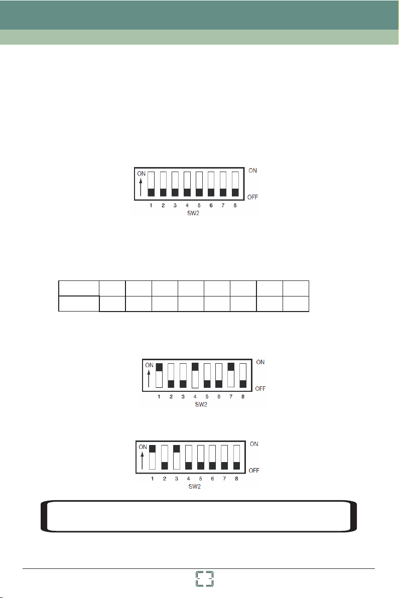
① SW2 is u sed t o set dome addres s. The bu tto ns from 1 to 8 are equi val ent to bit 0~bit 7
resp ect ively; “ON” sta tus o f each button means 1, w hil e “OFF” means 0.
n-1
The ID a ddr ess adopts binary syst em coding: n” sta nds for the bu tto n
numb er i n SW 2.
“OFF ” sta tus, the addres s is 2 =1; th e but ton 2 is set to “ON” st atu s , while others are set
to “OF F” st atus, the addre ss is 2 =2, a nd so o n. Please refer t o the b elow chart.
For exam ple : the button 1 is set to “ON” stat us , whi le o thers are set to
1-1
2-1
2 . whic h “
Button
Dome ID
1 2
3
4
21
5
4
7
6
8
1286432168
● For ex amp le: If you want to se t dom e address as “73", 73= 1+8 +64 means the but ton
1, 4, 7 sh oul d be set to “ON” status.
● For ex amp le: If you want to se t dom e address as “5", 5=1+ 4 means the button 1, 3
shou ld be s et to “ON” status .
tem,
ry sys
NOTE
h
ere w
: P
e d
le
o n
a
ot l
e set t
s
i
s
t o
he dia
e b
n
y o
l s
w
ne
ch corre
t
i
.
y acco rding t
l
t
c
2
o the bi n
a
Page 7
Chapter 1 Introduction
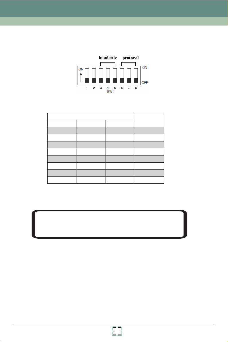
② The bu tto n 6, 7 and 8 in SW1 are use d to se t communicati on pr otocol. When the three
butt ons a re set to “0” , it is PEL CO- D; When a ny one of them is set t o “1” , it is PELCO-P.
③ The button 3, 4 a nd 5 in S W1 are used to set ba ud ra te
SW1
3
0
1
0
1
0 0
1
0
1 1 1
4
0 0
1
1
0
5
00
0
0
1
1
11
Baud Rat e
1200
2400
4800
9600
9600
9600
9600
9600
④ The camera ma y mal function if the s wit ches are not full y tur ned on/off. Please dou ble
chec k the s witches befor e fin ishing setup.
NOTE : Cha nge is effective after r ebo oting the camer a
You can ch ang e the protocol vi a sof tware menu.
Plea se re fer to chapter 4. 2.3 f or details.
3
Page 8
Chapter 2 Installation
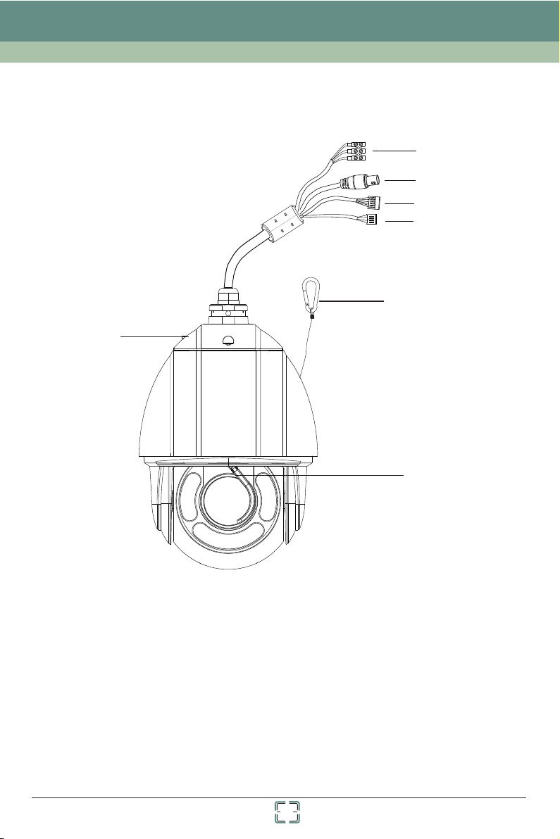
2.1 Interfaces and Parts
6
1
2
3
4
5
7
1 Powe r sup ply 2 HD-TVI Video O ut 3
RS42 2 Safe ty Wire Base Tr ay
4 5 6
7 Wiper
4
Alar m in/ out
Page 9
Chapter 2 Installation
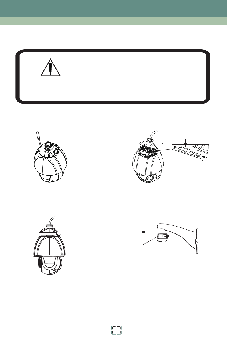
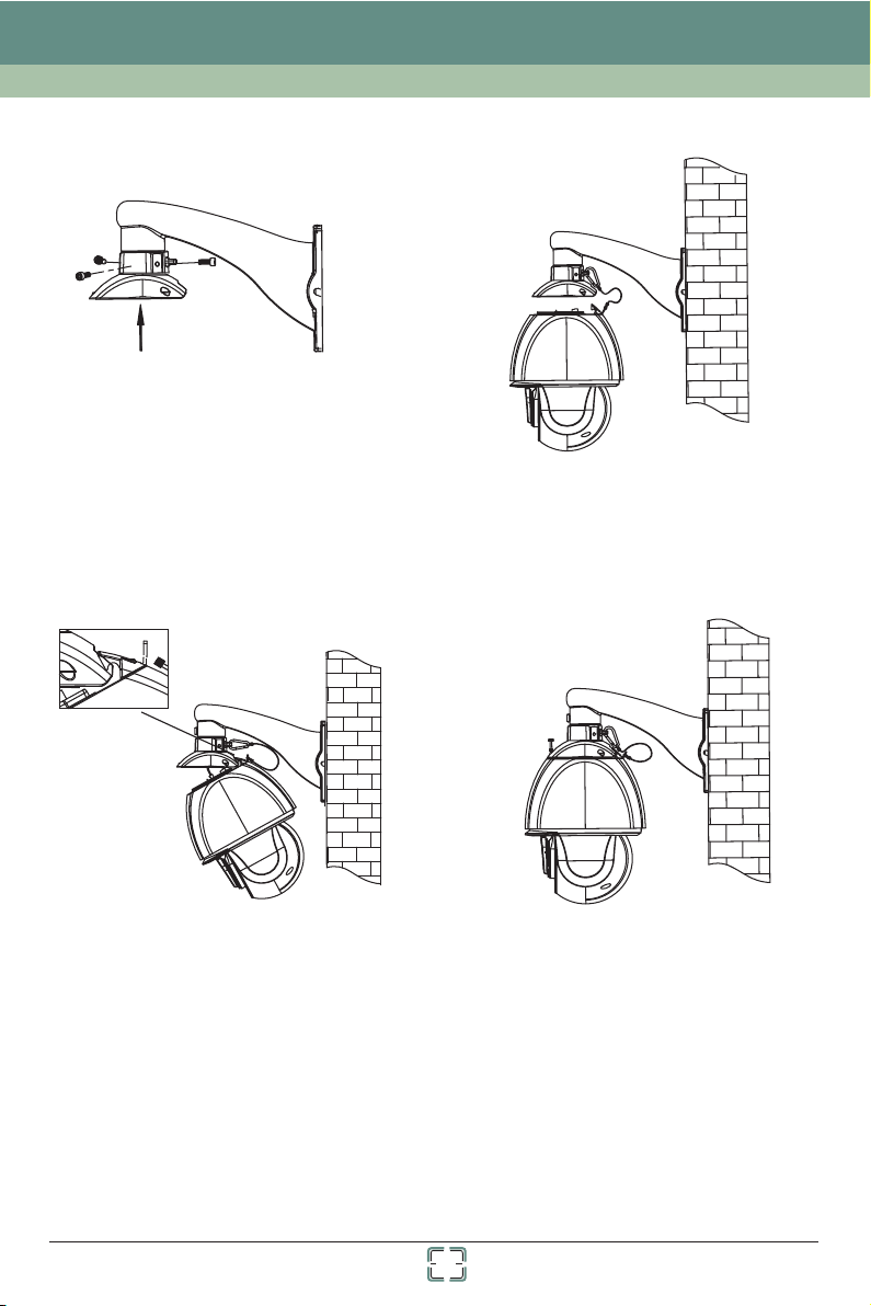
2.2 How to install
• Please make sure the wall is able to bear the
dome camera’s weight !
• Please make sure the dome camera is powered
off during installation!
WARNING
The in sta llation steps a re as f ollows:
• Please install the dome camera according to
the below steps!
Inse rt TF Card
① Loosen three screws of the base tray.
③ Unplug the cables and remove the base
tray.
② Open the base tray and insert TF card.
Tube
④ Fasten the tube to the bracket.
5
Page 10
Chapter 2 Installation
⑤ Pull the cables through the bracket. Then fix
the base tray to the tub with the screws.
⑦ Hook the camera to the base tray and then
conn ect t he cables.
⑥ Fix the bracket to the wall with the screws
and then hook the safety wire to the tub.
⑧ Secure the camera to the base tray with
the screws.
6
Page 11

Chapter 2 Installation
2.3 Connection
Connection End(AC 24V)
POW ER
VID EO
AL M- IN 1
AL M- IN 2
AL M- IN 3
AL M- IN 4
AL M- IN 5
AL M- IN 6
AL M- IN 7
AL M- IN -C OM
AL M- OU T1 +
AL M- OU T1 -
RS 4 22 T+
RS 4 22 TRS 4 22 R+
RS 4 22 R-
Power Connection(AC 24V)
AC24V A
Earth
AC24V B
Alarm Connection
1. Alar m Input
a) There are se ven i ndependent al arm i nput ports (ALM -IN 1~ALM-IN7) and one c omm on
port ( ALM -IN-COM).
b) Alar m input: connec t DC5 V~DC12V voltage between t he alarm input port ALM -Inx
(x=1 ~7) a nd the common por t (AL M-IN-COM).
7
Page 12

Chapter 2 Installation
c) Dis con nect the voltag e bet ween alarm inpu t por t(ALM-Inx(x=1~ 7) an d common
port ( ALM -IN-COM) to cancel t he alarm.
2. Alar m Output
a) Sup por t 1CH alarm outpu t inc luding OUT1+,OUT 1- co nnections; su ppo rt two input
mode s nam ely NO, NC.
b) Alar m output: suppo rt on ly one passive switc h for u ser to connect al arm d evices;
the al arm o utput state wil l be au to on/off according to y our s etting.
c) Ple ase r efer to below cha rt fo r the dome output stat e.
Output M ode
NO Outpu t
NC Outpu t
3. Exa mpl es
Input co nnectio n Outp ut Mode Outpu t Co nnect io n
ALM-IN
ALM-IN-COM
No Alarm In pu t
ALM-IN
ALM-IN-COM
DC5V~DC12V
DC5V~DC12V
Alarm In put
Whethe r to output
No
Yes
No
Yes
Connec tion betw een OUT 1+ and OU T 1-
Open Cir cuit
Short Ci rcuit
Short Ci rcuit
Open Cir cuit
OUT 1+
NO
OUT 1-
OUT 1+
NC
OUT 1-
OUT 1+
NO
OUT 1-
OUT 1+
NC
OUT1-
8
Page 13

Chapter 3 Basic Operation Guide
3.1 Startup and Shutdown
Befo re ru nning your came ra, p lease make sure all th e connections are do ne co rrectly.
Star tup : After the pow er su pply is connected, t he ca mera will be auto mat ically starte d
up and t hen t he system of the sp eed d ome is going to self-c hec k. The menu cannot be
oper ate d until success ful s elf-checking has d one .
Shut dow n: Disconnect the po wer cable.
3.2 Keyboard Setup
The ad dre ss, communica tio n protocol and baud ra te of the keyboard sho uld b e consistent
with t hat o f dome camera. Si nce d iffer ent keyboards h ave d iffer ent ways to set pro toc ol,
plea se re fer to relevant u ser m anual of keyboard fo r details.
Pann ing a nd tilting: use t he jo ystick of the contro ller
Cont rol ling zoom: move t he jo ystick clockw ise ( Tel e) or c ounterclock wis e (Wid e)
OSD co mma nds:
Joys tic k Up----move to the ab ove menu
Joys tic k Down---- move to the b elow menu
Joys tic k Right----selec t the sub-menu/exi t
Joys tic k Left----ret urn t o the previous menu an d sav e the setting
NOTI CE: P lease refer to th e use r manual of keyboard f or op eration decri pti on.
Call p res et 95 to enter the ma in me nu interface:
MAIN MEN U
1 SYSTEM I NFORM ATIO N ↓
2 SYSTEM S ETUP ↓
3 CAMERA SE TU P ↓
4 PRESET SET UP ↓
5 DOME FUN CTION ↓
6 DISPLAY SETUP ↓
7 WIP ER SETU P
8 LOAD DEFAULT ↓
0 EXIT
NOTE :The arr ow “↓”icon mean s the re is submenu to op era te.
↓
9
Page 14

Chapter 4 Menu Setup
4.1 System Information
You can ch eck t he version, cam era , temperature , dat e, dome ID, protocol a nd ba ud rate
of the s pee d dome camera in th e sys tem informati on in terface.
4.2 System Setup
Go to Ma in Me nu→System Setup as bel ow:
SYSTEM S ETUP
1 AUTO P T FL IP: OFF
2 LANGUA GE SETU P↓
3 RS422 SE TUP↓
4 DATE SETUP
5 TIT LE SETU P↓
6 NORTH SET UP↓
7 NEW PASSWO RD↓
8 CHANGE PASSWORD
0 RETURN
↓
↓
4.2.1 Auto PT Flip
This f unc tion is useful to m oni tor moving objects o r peo ple passing dir ect ly under the
came ra.
① E nable “AUTO PT FLIP” and then exi t men u.
② K eep on moving dow nwa rds so that the PTZ can fo llo w the object from o ne si de to
anot her s ide, ensuring a n obj ect or a person passin g dir ectly under the d ome i s always
moni tor ed.
4.2.2 Language
Our pr odu ct supports Englis h.
4.2.3 RS422 Setup
Go to Ma in Me nu→System Setup→R S42 2 Set up as below:
10
Page 15

Chapter 4 Menu Setup
RS422 SE TUP
1 RS422/ ID SEL: H/W
2 DOME ID: 0 01
3 PROTOCOL : PE LCO-D
4 BAUD RATE: 2 40 0
0 RETURN
RS42 2 Sel ection: H/W (hardwar e) an d F/W (so ftware) are sel ect able. It is effective to
set th e com munications w hen s electing F/W. Otherwise t he do me communicat ion i s in
acco rda nce with dial swi tch es.
Dome I D: Ra nge from 001 to 255 .
Prot oco l: Support PELC O-D a nd PE LCO-P.
Baud R ate : Th e bau d rate is selecta ble f rom 1200bps to 96 00b ps.
NOTI CE: T he change to comm uni cation setup will ta ke effe ct after reboot ing .
The co mmu nication of key boa rd should be modifie d correspondingl y.
4.2.4 Date Setup
Go to Ma in Me nu→System Setup→Time Setup inte rfa ce as below:
DATE SETUP
2012-0 6-01 12:0 0:00
CALL 1 TO STORED
CALL 2 TO CANCE L
① M ove the joystic k of th e controller in a ll fo ur directions to sel ect the desired
para met ers.
② C all 1 to save the set tin g.
4.2.5 Title Setup
The st eps t o set dome title ar e sam e with that of date s etu p. Please refer to sec tio n 4.2.4
for de tai ls.
11
Page 16

Chapter 4 Menu Setup
4.2.6 North Setup
Go to Ma in Me nu→System Setup→Nort h Set up interface as b elo w:
NORTH SET UP
CALL 1 TO STORED
CALL 2 TO CANCE L
① M ove the joystic k in al l four directio ns to c hoose a location. Ca ll pr eset to sa ve
the co nfi guration.
② T he horizontal a ngl e will treat the no rth p osition as a referen ce; otherwise it wil l
trea t the h orizontal ori gin a s a reference to di spl ay the clockwise rot ation angle of camer a.
③ T he vertical PTZ w ill t reat its highes t poi nt as a reference ( whe n the camera is
para lle l with the horizo nta l ground) to show the in cluded angel betwe en th e camera and
hori zon tal ground.
4.2.7 New Password and Change Password
New Pa ssw ord :
NEW PASSWO RD
ENTER PASSWORD:
--- - - -
CONFIR M PASSWOR D:
--- - - - -
CALL 1 TO STORED
CALL 2 TO CANCE L
Set pa ssw ord by preset: Prese t+N +Enter(plea se re fer to the instru cti on of the keyboar d
for de tai ls).
Numb ers f rom 1 to 9 are availa ble . Th e pas sword should be 6 char acters.
Empt y pas sword is invali d whe n creating new passw ord .
Pass wor d need to be input when yo u log in next time.
1
Chan ge Pa ssw ord
12
Page 17

Chapter 4 Menu Setup
CHANGE PASSWORD
ENTER PASSWORD:
*** * * *
ENTER NE W PASS WORD:
--- - - -
CONFIR M PASSWOR D:
--- - - -
CALL 1 TO STORED
CALL 2 TO CANCE L
Inpu t the c urrent passwo rd an d then input the new pas swo rd twice (enter ing e mpty new
pass wor d means to delete t he cu rrent password).
4.3 Camera Setup
Ente rin g Main Menu→Camer a Set up brings the follow ing s creen.
CAMERA SE TU P
1 CAMERA FU NCTION↓
2 IMAGE SE TUP↓
3 FOCUS NE AR LIMI T: 1M
4 ZOOM SPE ED: FAS T
5 DZOOM: O FF
6 PAL/NT SC: PAL
7 DAY NIG HT MOD E: AUTO
8 DAY NIG HT TIMER
9 LENS INI TIALIZE ...
.
0 RETURN
↓
4.3.1 Camera Function
13
Page 18

Chapter 4 Menu Setup
CAMERA FU NCTION
1 BLC: OFF
2 HLC: OFF
3 HLC LEVE L: 20
4 3D-DNR : Low
5 COLOR LE VEL: 06
6 SHARPN ESS: 06
7 WDR : OFF
8 GAMMA: D EFAULT
9 CAM DEFO G: OFF
0 RETURN
BLC: I mpr ove the brightn ess o f the foreground whe n bac k light is so stron ger t hat the
fore gro und is dark.
HLC: E ffect ive ly control the ph eno menon of large halatio n and v ague images cau sed b y
the hi gh li ght sources fro m the c amera lens. Meanwh ile, this function c an al so compensate
the hi ghl ight area to get mo re cl ear images.
HLC Le vel : Select high lig ht co ntrol level.
3D-DNR: Reduce the noise of the brightness and chroma of the image in low illumination condition.
Colo r Level : Adjust the scree n lev el.
Shar pne ss: Set the image d efi nition.
WDR: Wi de dynamic rang e. If WDR i s on, y ou can see the high lig ht, the shadow an d the
back lig ht area clearly.
Gamm a: Me asurement the c ont rast of an image.
CAM De fog : Recover the vid eo de gradation caused b y fog , rain, or even dus t on yo ur lens.
4.3.2 Image Setup
IMAGE SE TUP
1 AE MODE F-A UTO
2 BRIGHT: 1 0
3 SHUTTE R: 05
4 IRIS: 13
5 AGC: 11
6 WB MO DE: ATW
7 RED GAIN <MWB> : 12
8 BLUE GAI N :15
9 IMAGE FL IP: OFF
0 RETURN
<MWB>
14
Page 19

Chapter 4 Menu Setup
AE Mod e: F- Auto, Bright, Shut , IRI S and Manual are op tio nal.
Brig htn ess : Range from 00 (da rkest) to 20 (bright est ). Adjust the s cre en brightness .
Shut ter : Th e low er the value of shu tte r is, the brighte r the i mage is. It is availab le only
when t he AE mode is set to man ual m ode.
IRIS : The hig her t he value of the cam era I RIS is, the more th e lig ht gets. It is availab le only
when t he ca mera is IRIS or Man ual m ode.
AGC: The larger the nu mbe r is, the higher th e bri ghtness and the m ore t he noises of the
imag e are .
WB Mode: White Balance Mode. The auto, manual and ATW mode are available. The white
bala nce m enu adjusts the b ala nce of the screen c olo rs under different lig hti ng conditions.
Red Gain<MWB >: The operation is effective only when the white balance is in manual mode.
Blue Gain<MWB >: The operation is effective only when the white balance is in manual mode.
Imag e Fli p: Flip the image .
--Mi RR: Turn over the image l eft o r right.
--Fl ip: Turn over the image u p or do wn.
--Ro ta: Turn over the image u p, do wn, left or right .
4.3.3 Focus Near Limit
Set the ne arest dis tance of fo cus.
4.3.4 Zoom Speed
Adjust z oom speed .
4.3.5 DZoom
To tur n on/ off the D-z oom mode. Af te r enabl in g digit al z oom mod e, d igita l zo om will b e increas ed
on the bas is of optic al zoom.
4.3.6 Video Format
To cho ose vid eo f ormat : PAL/NTS C.
4.3.7 Day & Night Mode
Day&Ni ght mod e in clude s fo ur mode s: Au to, Night , Day and Time r.
--Auto : Th e ca mera wi ll automa tically s witch the m ode betwe en day and ni ght as per th e ambient
illumi nation.
--Nigh t: The c amera w ill be nigh t mode at all t ime. You’d b etter use t his mode at n ight.
--Day: The c am era wil l be day mode a t all time. You’d bette r use this mo de in dayti me.
15
Page 20

Chapter 4 Menu Setup
--Tim er: The camer a will regu larly swi tch the mod e between d ay and ni gh t.
Day & Ni gh t Time r Setu p:
Go to Day Ni ght Timer me nu as shown b elow:
DAY NIG HT TIMER
1 BW ON T IM E:
19:00
2 COLOR ON TIM E:
.
Set the ti me of the BW mode a nd C olor mo de and then c all prese t 1 to save the s ettings .
4.3.8 Lens Initialization
The came ra lens wil l resto re t o the fac to ry defa ul t setti ng a fter yo u en able “L en s Initi al ize.. .” .
4.4 Preset Setup
This f unc tion is used to mem ori ze the specific posi tion of pan, tilt, zoo m and f ocus,
givi ng mu ch convenienc e for q uick return to th is po sition by calling pr ese t.
① Retu rn to t he live and move th e joy stick to select a l oca tion. Then call preset 9 5 to
ente r the m ain menu interf ace . Selecting the p res et setting menu b rin gs up a screen as
show n bel ow:
07:00
CALL 1 TO STORED
CALL 2 TO CANCE L
PRESET SET UP
1 TIT LE DISP : OF F
2 CUR PRES ET NO: 0 01
3 PRESET SET TI NG↓
4 DEL CUR P RESET…
5 DEL ALL PRE SET↓
0 RETURN
②
Select the current pr ese t number.
③ Ente r Pre set Setting int erf ace as below:
16
Page 21

Chapter 4 Menu Setup
PRESET SET TI NG
PRESET NO: 0 01
TIT LE: --- -- -----
CALL 1 TO STORED
CALL 2 TO CANCE L
④ Move t he jo ystick in all fou r dir ections to select th e numbers or letters f or se tting the
titl e. The ti tle w ill display on th e scr een when passin g tho ugh the preset if t he ti tle display
has be en en abled
NOTE : There i s ano ther way to set pre set : Number+Pres et( please refer to the us er
manu al of t he keyboard you a re us ing. Th is shortcut doe s not s upport title setup .
4.5 Dome Function
Dome f unc tion includes s eve n sub-menus: Patro l Set up, Grouping Se tup , Task Se tup ,Trace
Setu p, Alarm Setup, Pr iva cy Mask and Home Posit ion .
4.5.1 Patrol Setup
Ente r Mai n Menu→Dome Funct ion→P atrol Setup as below :
PATROL SET UP
1 PATROL NO: 1
2 EDIT CUR PATROL↓
3 RUN CUR PATROL …
4 DEL CUR PATRO L↓
0 RETURN
In thi s int erface, by prog ram ing presets in patro l list in advance, the s yst em will keep
call ing t hose presets at t he se t time in sequenc e whe n executing patrol c ommand so that
non- sto p monitoring be twe en multiple imp ort ant positions can be a chi eved.
Step s are fol low ing:
① E nter the “Edit Cu rre nt Patrol” inte rfa ce as below. This c amera supports 8 pat rol s
with 1 6 pre sets each set.
17
Page 22

Chapter 4 Menu Setup
② Move t he jo ystick upward o r dow nward to control the c urs or; move the joys tic k right
or lef t to ch ange the parame ter. The p reset ranges fr om 00 1~255 and the dwell ti me ranges
from 0 5~2 40s.
③ When s ett ing the patrol, p res sing “IRIS OPEN” wil l inc rease the value b y 10. p ressing
“IRI S CLO SE” will decrea se th e value by 10. Call 1 to sav e the setting.
FORMAT: PRE N O. / TIME (S EC )
01: 001/ 007 02: 002 / 005
03: 000/ 005 04: 000 /005
05: 000/ 005 06: 000 /005
07: 000/ 005 08: 000 /005
09: 000/ 005 10: 000 /005
11: 000 /005 12: 00 0/005
13: 000/ 005 14: 000 /005
15: 015/ 005 16: 000 /005
CALL 1 TO STORED
CALL 2 TO CANCE L
④
In the p atr ol setup interf ace , select “Run The Curren t Pat rol” item to exec ute t he
comm and . Th e cam era will automa tic ally keep runni ng ac cording to the pa tro l you set until
new co mma nd is received. The corr esp onding operat ing i nformation will di spl ay on the
scre en wh en the camera is ru nni ng.
4.5.2 Grouping Setup
Go to Ma in Me nu→Dome Functio n→Gro uping Setup as below :
GROUPI NG SETU P
1 EDIT GROUP ING
2 RUN GROU PING. ..
3 DELETE G ROUPING↓
0 RETURN
Go to “E dit G rouping” menu a s sho wn below:
18
↓
Page 23

Chapter 4 Menu Setup
EDIT GROUP ING
FORMAT: PATNO
01: PAT1 02: PAT2
03: PAT3 04: PAT4
05: PAT5 06: PAT6
07: PAT7 08: PAT8
YES: CAL L PRESET 1
NO : CALL PRESET 2
Eigh t pat rols in a group can b e set . PAT 1 stands for Patrol 1, PAT 2 stand s for P atrol 2 and
so on.
Sele ct “R un Grouping” to r un th e patrols in order.
Sele ct “D elete Groupin g” to d elete the patro l gro up.
4.5.3 Task Setup
Ente r Mai n Menu→Dome Funct ion→Task S etu p as below:
TASK SET UP
1 TASK: OF F
2 TASK SET TI NG↓
3 DEL CUR PATRO L↓
0 RETURN
By div idi ng 24 hours into sever al periods and appoi nti ng different command s for e ach
peri od, t he camera syste m wil l automatical ly ex ecute the comma nds a ccording to the set
time i f the re is no operatio n.
① E nable the task fu nct ion;
② E nter the task set tin g interface as be low. Move the j oys tick in all four di rec tions to
chan ge th e parameters.
Time Format : Sta rt Time--En d Time . Th e tas ks will be automa tic ally arranged i n ord er
depe ndi ng on the start tim e so th at each task will b e exe cuted one by one.
Task Typ e: RSC, ASC, PRE, PAT, TRA.
19
Page 24

Chapter 4 Menu Setup
.
NOTE : The h ome position fu nct ion will be disabled i f enabling task sett ing .
4.5.4 Trace Setup
Ente r Mai n Menu→Dome Funct ion→Track Setu p int erface as below :
T ASK SET TI NG
1 08:00 – 11:59 : PRE : 99
2 12:00 – 13 :59 : PAT : 01
3 00:00 – 00 :00 : NON: 01
4 00:00 – 00 :00 : NON: 01
5 00:00 – 00 :00 : NON: 01
6 00:00 – 00 :00 : NON: 01
7 00:00 – 00 :00 : NON: 01
8 00:00 – 00 :00 : NON: 01
CALL 1 TO STORED
CALL 2 TO CANCE L
TRA CE SETU P
1 TRA CE NO: 1
2 TRA CE SETT IN G↓
3 TRA CE RUN…
4 DELETE TRA CE↓
0 RETURN
This f unc tion is used to mem ori ze the operatio n to PT Z, zoom, focus so that r epe ating
oper ati on process can be r eal ized by running trac e.
① C hoose the curre nt tr ace number;
② E nter the trace se tti ng. Press “IRIS-” an d move the joystick in a ll fo ur directions t o
cont rol t he dome camera. Then cal l pre set 1 to save the set tin g.
Noti ce: E ach trace can mem ori ze up to 180s. If the t ime e xceeds 180s, the sys tem
will automatical ly save the operation data and return to the previou s menu. In
addi tio n, up t o 360 com mands can be memo rized for each trace. If exceeding
360 commands, the sy stem wil l automa tic ally sav e the fi rst 3 60 commands and
then exit the current inte rface. The recording tim e is rel ate d to the operating
freq uen cy. The m ore freque nt the opera tio n is , t he shorter t he memory ti me is .
20
Page 25

Chapter 4 Menu Setup
③ S elect “Tr ace R un…” item to perf orm t he command.
4.5.5 Alarm Setup
Ente r Mai n Menu→Dome Funct ion→A larm setup as below:
ALARM SET UP
1 ALARM IN CO NDITION : N.O.
2 OUTPUT ENA BLE: ON
3 EDIT ALARM
4 ALARM TIMER
0 RETURN
Alar m In Co ndi tion: Set the ala rm input type to be Norm all y Opened (N.O.) o r Nor mally
Clos ed (N .C.) accordin g to th e sensor type.
Outp ut En abl e: If “ON” is selec ted, the camera will o utp ut alarm inform ati on on an alarm.
Edit Al arm : Go to “Edit Ala rm” menu as shown belo w.
EDIT ALARM
1 ALARM IN NO : 7
2 ALARM IN MO DE: ON
3 ALARM CAL L: P RE56
YES: CAL L PRESET 1
NO : CALL PRESET 2
↓
↓
Alar m In NO : Select alarm in put n umber.
Alar m In Mo de: ON, OFF and Time r are o ptional.
Alar m Cal l: Call the prese t you n eed. Wh en the first alar m inp ut happens, the came ra will
auto mat ically switch t o thi s preset to monit or.
Alar m Timer: Go to “Al arm Timer” menu as s how n below.
ALARM TIMER
1 ENABLE : OFF
2 ALM TI ME: 00: 00
3 DISARM TIM E: 00:00
YES: CAL L PRESET 1
NO : CALL PRESET 2
21
Page 26

Chapter 4 Menu Setup
① E nable “Alarm Tim er”.
② Set alarm time and disalarm time.
When “Timer” i s selecte d in alarm mo de, the cur rent alar m input can t rigger
relevant alarm during this period when the alarm occurs.
NOTI CE: I f the dome is on the me nu st ate when alarm is trig ger ing ,
any co mma nd is negative.
4.5.6 Privacy Mask
Go to th e Mai n Menu→Dome Funct ion→P rivacy Mask interf ace a s below:
PRIVACY MASK
1 MASK NO: 1
2 MASK COL OR:
3 CREATE MAS K
4 DEL CUR MA SK. . .
5 DEL ALL MA SK↓
0 RETURN
BLACK
↓
Mask N O: Se lect the curren t mas k area. Eight mas k are as can be set at most.
Mask C olo r: Select the col or to m ask.
Create Mask : Go to t he “Create Mask ” sub -menu and then set the m ask area by moving the
joys tic k. After that , cal l preset 1 to save the mas k area.
Dele te Cu rrent M ask: Select thi s men u to delete the cur ren t mask area.
Dele te All Mask: Selec t thi s menu to delete al l mas k areas.
4.5.7 Home Position
Ente r Mai n Menu→System Set up→Ho me Position interf ace a s below:
HOME POS ITION
1 HOME: OF F
2 HOME SET : 001 (P RE)
3 DELAY TIM E : 00 7(SEC )
0 RETURN
22
Page 27

Chapter 4 Menu Setup
①M ove the joystic k upw ards or downwards to e nab le the home posit ion f unction.
②T hen select pres et wh ich has been set in a dva nce.
③S elect delay tim e and e xit the menu. When the sta nd- by time of the dome c ame ra exceeds
the de lay t ime, the camera w ill a utomaticall y exe cute the comman d to mo nitor the selec ted
pres et.
NOTE : Del ay time range fro m 005 s to180s
4.6 Display Setup
You can en abl e title display, time displa y, tempe rat ure display, camera OSD d isp lay,
orie nta tion display or s yst em display if you need .
4.7 Wiper Setup
Go to Ma in Me nu→Wip er Se tup as shown bleo w.
WIP ER SETU P
1 SPEED LE VEL: MIDD LE
2 RUN TIME: 1M IN
3 START ...
4 STO P ...
0 RETURN
① Set the speed level and run time.
② S elect “START” to enable wipe r fun ction.
4.8 Load Default
Mast er Rese t: Re store the camer a sta te and active men u to fa ctory default b ut do n ot clear
thos e par ameters such as d ome t itle, dome ID, proto col, baud rate, pres et, p atrol and so on.
Mast er Clea r: Re store the camer a to fa ctory default .
Syst em Re boo t: Reboot the cam era.
Firm ware Up dat e: It is used for upd ati ng the dome camer a sys tem by RS422 BUS.
Firm war e update will del ete t he dome system softw are, which will resu lt in f ailure to work .
Plea se be c autious! If you w ant t o update the camera’s system, please m ake c ontact with
us to ob tai n a new software pa cka ge firstly!
23
Page 28

Chapter 4 Menu Setup
PS: Preset Description
Call P res et
Set Pr ese t
Call P res et 90
Call P res et 91
Call P res et 92
Call P res et 93
Call P res et 94
Call P res et 95
Call P res et 97
Call P res et 99 Enab le P- P SCAN
Set Pr ese t 91
Set Pr ese t 92
Set Pr ese t 93
Run tr ace 1
Run pa tro l 1
Run pa tro l 2
Run pa tro l 3
Run pa tro l 4
OSD me nu
Enab le ra ndom scan
Set ra ndo m scan, TASK auto call the
begi nni ng point
Set le ft bo rder of P-P SCAN
Set ri ght b order of P-P SCA N
24
Page 29

Appendix A Troubleshooting
Problem
No ima ge an d no action
when p owe r is input
The im age i s not stable
The im age i s vague
The im age h as a lot of
nois e
Norm al se lf-check
but no i mag e
Norm al se lf-check
but ou t of co ntrol
Abno rma l self-check
Not st abl e control
Cause and Solution
Chec k if th e power cable is no rma l or misconnected
Chec k if th e video cable is pr ope rly connected
Chec k if th e power supply is e nou gh
Chec k if th e dome cover or the l ens i s stained with dirt
Chec k if th ere is strong int erf erence source
surr oun ding the dome
Remo ve th e protective co ver o f the camera lens
Chec k if th e video cable is pr ope rly connected
Chec k if th e RS422 bus is properl y connected
Chec k if th e Dome ID, commun ica tion protocol setu p
is rig ht
Chec k if th e protective fo am is r emoved
Chec k if th e power meets the r equ irement.
The al arm o utput or
pres et is n ot working
Chec k if th e alarm device is w ork ing
Chec k if th e alarm in/out ca ble i s connected
Chec k if al arm input is enab led
25
Page 30

Appendix B Specification
Camera
System
PTZ
Genera l
Image Se nsor
Eff ectiv e Pi xel
Horizo ntal Reso lution
Min. Ill uminati on
Lens
IR Distance
SNR
Focus Mo de
Day/Ni ght
BW
Alarm In put
Alarm Ou tput
Auto Fli p
Preset
Patrol
Tra ce
Scan
Home Pos ition
Task
Pan Rang e
Pan Spee d
Til t Ra nge
Til t Sp eed
OSD
Input Volta ge
Video Out pu t
Contro l Method
Power Co nsumpti on
Work in g Envir on ment
Protec tion Leve l
Weig ht
Dimens ion
1/3 Inch P rogress ive CMO S
1920(H ) x 1080 (V) 2 Me ga
1000 TVL
0 Lux
20 x Zoom, f = 4 .7-94mm , F1.6 ~ F3.5
100 m
>50dB
Auto/M anual
Auto/M anual/Timer
Auto, ATW, man ua l
7CH
1CH
YES
255
8
4
2
Yes
Yes
360°en dless rot ation
Preset: 240°/s,Manual Control Speed: 0.5~90°/s
0~90°( auto- rotatio n)
Preset: 240°/s,Manual Control Speed: 0.5~90°/s
Englis h
AC24V/ 3000mA
HD-TVI 1 .0Vp- p, 7 5 , Ω PAL/NT SC
RS422/ RS485, PE LCO-D / P EL CO-P
15W / Max 65W( IR on, he at er on)
- 20°C ~6 0 / Le ss than 9 5% (RH )°C
IP66
5KG
ф216mmx 349mm
26
Page 31

450011000583 A0
 Loading...