

Page 1

Analog HD IR
INTELLIGENT SPEED DOME CAMERA
USER INSTRUCTION
USE/INSTALLATION
Co py ri gh t( c) 20 15 (V 2. 5e di ti on )
Page 2

Sp eci al Dec lar ati on
Bef ore co n nec t ing an d u sin g t his de v ice, plea se read thi s ma nua l ca re ful ly
and p rope r ly pr e serv e d for r e fer e nce i n t he fu t ure.
This manua l may cont a i n s o m e inacc u r ate p lace in t e c hnolog y, or s ome
pri n tin g e rror. The c o nten t s of th i s manu a l wi l l upd a t e f r o m t i m e t o tim e , but
wit h out n o tice i f t her e i s any u p gra d es; U pdat e c ont e nts wi l l b e a d d e d i n ne w
ver s i o n manua l . W e wi l l improve o r u p d a t e th e p r o du c t o r p r o g ram o f t h i s
man u al at a n y tim e .
Page 3

CAUTION
Careful Transport
Du ri ng tra nsport, c us tody and in st all proce ss s hould pre ve nt w eight, se ve re
vi brat io n and soak da ma ge to produ ct .
Do Not Disassemble Zoom Camera
In ord er t o well matc h ni ght visio n, w e sell IR spe ed d ome camera wi th z oom
ca me ra , pl ease not di sa ssemb le z oo m camera if the re i s no techni ca l pe rson.
Power Supply, Vi de o Ca bl e an d Co nt ro l Cable
ca ution
For powe r su pply cabl e, v ideo cabl e an d control cab le , please ad op t shielde d
ca bl e and indep en dent wiri ng , can not mix wit h other cable s.
Electric Safety
Sh ou ld obey all k in ds of elect ri c standard wh en using spee d do me camera,
ma ke s ur e signal ca bl e ke ep enough d is tance(a t le ast 50m)w it h high voltag e
eq ui pment or ca bl es. If it is po ss ible, ple as e take lightn in g and surge
me as urement .
Clean
Wh en c lean came ra hou si ng, pleas e us e dry soft cl ot h to wipe, If i t is t oo
di rt y, plea se u se neutral clea ner to wipe l ig htly. Do no t use stron g or g rind
cl ea ner to preven t it s housing f ro m sc ra tching.
Strictly Sealed
Prev en t liquid or o th er things g et i nto speed d om e housing , el se it will ca us e
pe rm anent dam ag e.
Please do not use camera beyond limited temperature and humidity
Sp ee d dome came ra wor king temp erat ur e : -25℃ to 5 0℃, humidity le ss t han
90 %.
Please do not install camera near air conditioner’s outlet
Un de r fo llowing s it uation, l en s will be fog ge d because o f co ndensat io n:
*U se u nder the envi ro nment whe re t he t emperatur e ri se and down
freq ue ntly whic h ca used by the a ir c onditio ne r power on an d of f fr equentl y.
*U se i n environme nt w hich can ma ke g la ss fog.
*U se i n environme nt f ul l with smok e or d ust.
Ple ase do not make camera toward to strong light source, such as the sun
Towa rd camera to stro ng l ight source f or a l ong time wi ll d amage the c ol or
fi lt er on CCD or CM OS , th en it will ma ke i mage lose c ol or.
-1 -
Page 4

CONTENTS
Chapter 1 Product Overview .............................................................................3
1. 1 Pr od uct featu re s ......................................................................................3
1. 2 Sp eed dome Paramete r............................................................................3
1. 3 St ructure Dim en sion................................................................................4
Chapter 2 Installation ........................................................................................8
2. 1 In st all Instr uc tion....................................................................................8
2. 2 In st all Metho d..........................................................................................8
2. 3 Ba ud rate Setup .....................................................................................17
2. 4 Ad dress Set up ........................................................................................17
2. 5 Powe r su pply and Co nt rol cable Con ne ction .........................................18
2. 6 Co nnectin g Me thod................................................................................18
2.7 Cabl e Ma rk Instruct io n ..........................................................................19
2. 8 Typical w ir ing diagram ...........................................................................19
Chapter 3 Basic Operation..............................................................................20
3. 1 Se lf-t est when powe r on .......................................................................20
3. 2 Pr eset setu p...........................................................................................20
3. 3 Ca ll preset .............................................................................................20
3. 4 Fu nc ti on R ea li za ti on By Preset .............................................................21
3. 5 Pa tr ol S et ti ng .........................................................................................25
co ntents
Chapter 4 App en di x .........................................................................................26
4.1 FAQ s .......................................................................................................26
4.2 Cl ea n the transpa re nt c over ..................................................................26
4.3 Li gh tning and S ur ge p rotecti on .............................................................27
4.4 RS 48 5 bus wirin g ...................................................................................28
-2 -
Page 5

Chapter 1 Product Overview
1.1 Product Feature
Strong Intelligent Function
• PELCO- D/P,Hikvisi on ,Dahua and ot he r control p ro tocol aut o di agnosis .
• 2400 .4 800,960 0 ba ud rate auto di ag nosis.
PTZ Control
• Usin g RS 485 Proto co l, Video Tran smissio n Di stance 50 0m i n theory.
Product Fea tu re
• Pan 0-360 de gr ee contin ue r otate, ti lt 0 -90 degree, n o mo nitor bli nd
spot .
• Supp or t CCVC, Con tr ol Speed Do me C amera Speed . Th e Zoom w il l
auto a dj ust accordi ng t he lens zoo m
Night vision function
• Turn on the ir li gh t according t o th e backlig ht s trength.
• adju st t he ir light ’s bri gh tness lev el a cc ording to t he z oo m times.
1.2 Speed dome camera parameter
Electric
Rated Vol ta ge
De co der Bu il t in IR d istance
Co mmu ni catio n proto co l
Ba ud rate(RS485)
Pan rot at e
Sp ee d
Op erate
environment
Weather-proof level
Installation mode
-3 -
DC 12V 4A±10%
Set
PE LCO -D /P HI K/ DAHUA
24 00/4800/9600bps/aut o id en ti fy
Opera te
36 0 endless Tilt rotate
Preset
Mi ddl e Spe ed :Pa n 6~3 0 °/ S
Til t 4~ 17 °/S
Hi gh Sp eed :Pa n 0. 1~2 00 °/S
Til t 4~ 30 °/S
Environ me nt
Ou tdoor: -20℃~60℃
Indoor: -10℃~50℃
IP 66
Physica l
Power
Co ns umption
ID
Mo ni tor
mo de P reset.
environment
hu midity
Wal l mo un t/ ce il in g mo un t
10 M ax at daytime, 30Ma x
at n ight(without heatin g)
10 0- 120m
1- 25 5
90 d egree
12 8
pa trol,pan scan and
pa ttern scan
0- 95 % without
co ndensation
Page 6
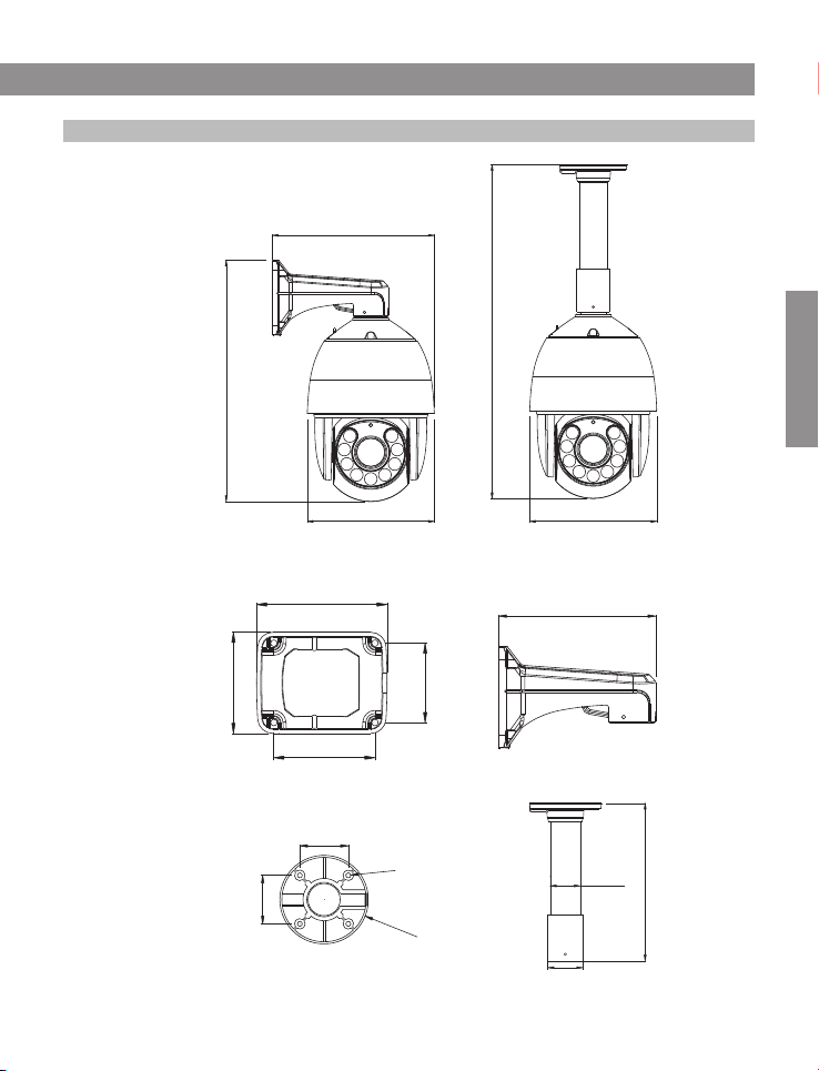
1.3 Structure Dimension
H type s pe ed dome Dim en sion
Chapter 1 Product Overview
279.7
H ta pe b ra ck et Dimens io n
Wall mount b racket
Ce il ing mount b rack et
577.2
Di me nsion
416.9
219.6 219.6
129.0
100.0
100.0
63.0
63.0
78.5
4
∅6.
∅
115.0
200.0
48.7
uni t:mm
uni t:mm
255.0
57.0
uni t:mm
-4 -
Page 7
Chapter 1 Product Overview
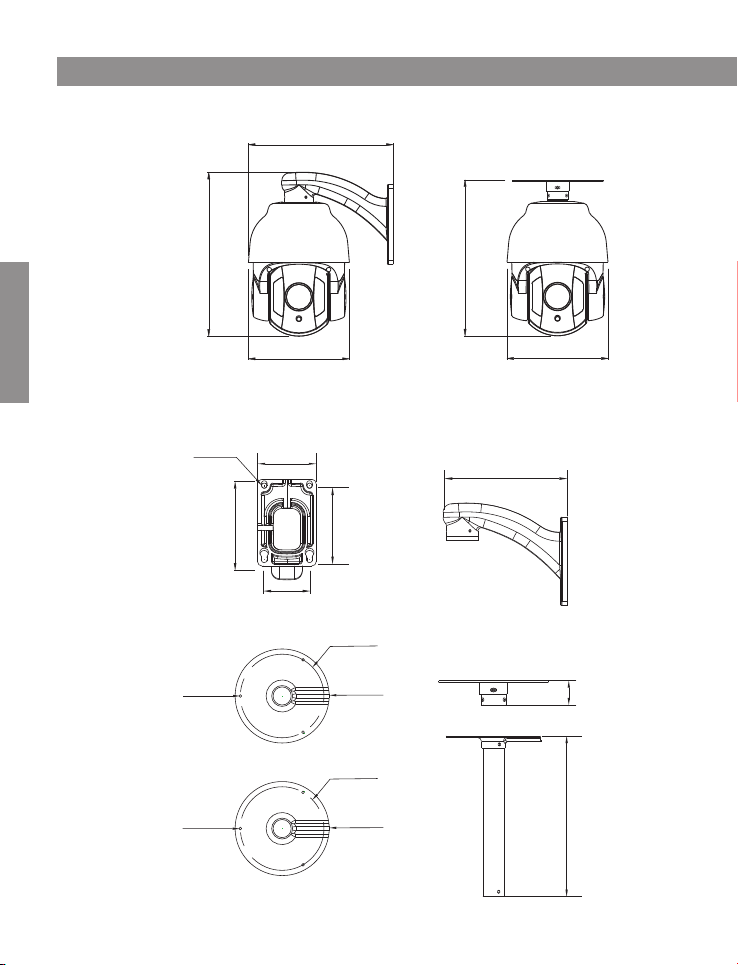
R type s pe ed dome Dim en sion
214.9
Di me nsion
R type b ra ck et D imensio n
Wal l mount b racket
Ce il ing mount b rack et
4XΦ7.0
3X
∅
3X∅4.0
243.2
117.7
4.0
150.0
79.7
61.5
100.7
∅
∅
∅120.0
∅135.0
120.0
135.0
231.7
150.0
165.2
uni t:mm
20
uni t:mm
229.0
-5 -
uni t:mm
Page 8
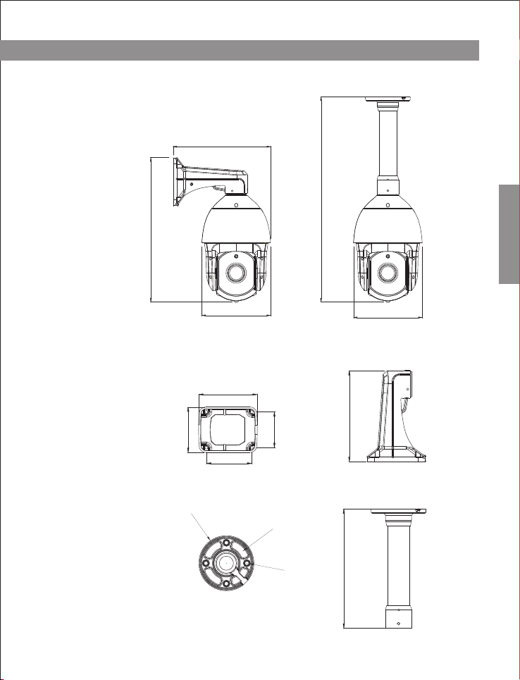
N type s pe ed dome Dim en sion
388.2
Chapter 1 Product Overview
262.4
551.9
Di me nsion
N type b ra ck et D imensio n
Wall mount b racket
Ce il ing mount b rack et
185.0
129.0
∅90.
78.5
2
4
-∅
9.1
100.0
100.0
∅
121.
0
185.0
200.0
262.5
uni t:mm
uni t:mm
-6 -
Page 9
Chapter 1 Product Overview
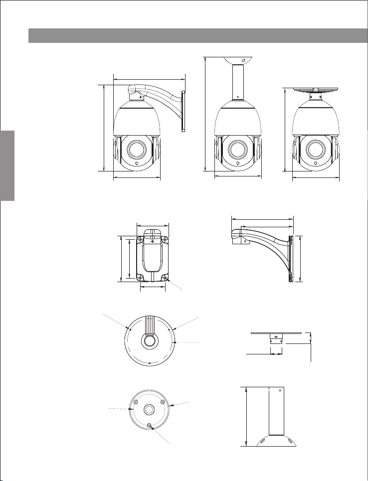
U type s pe ed dome Dim en sion
208.0
Di me nsion
U type b ra ck et D imensio n
Wal l mount b racket
Ce il ing mount b rack et
-7 -
251.1
136.1
80.0
96.0
114.9
4x∅7.0
62.0
3-
∅4
.
0
∅66
.
1
∅3.5
332.8
241.2
136.1
154.0
130.0
.0
135
∅
∅
120.0
30.9
83.7
∅
124.3
136.1
uni t:mm
114.6
29.9
uni t:mm
Page 10
Chapter 2 Installation
2.1 Install Instruction
Prep are before inst al lation
In ord er t o prevent tro ub les, inst al lation sh ou ld be done by pro fe ssional s ta ff
ba se o n corresp on ding rule s.
Co nf irm all spa re -parts are co mp lete, ens ur e applica ti on of this sp ee d dome
ca me ra a nd i nstal la tion mode is su itable for re qu irement.
Installation
Wall/cei li ng mount sp ee d dome comp os ite with brac ke t, z oom camera,
transp ar ent cover and o th er parts.
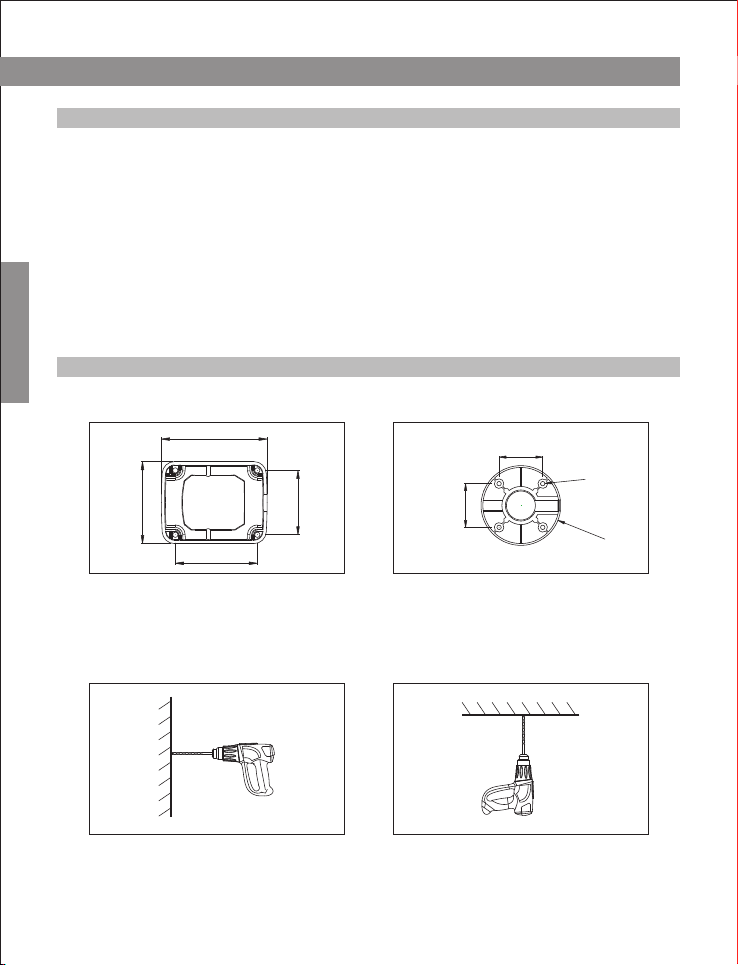
2.2 Installation Method
H type s pe ed d om e camera installation m et ho d
129.0
100.0
100.0
Wal l mo unt b racke t
78.5
St ep 1 -Draw positio ni ng holes
Take o ut b ra cket from packa ge b ox, mark the ho les’ posit ion based on wall
mount bracket bo tt om 4pcs insta llation hol es.
63.0
∅6
63.0
Ce ili ng m ount br ack et
4
.
∅1
15
.
0
St ep 2 -Drill ho le s and put exp an sion scre ws i n
Dr il l 4pcs expa ns ion screw 's i nstalla ti on holes at p re -marked pos it ion, then
pu t 4p cs expans io n screws in.( No te: p le ase bri ng e xpa ns ion scr ew s own .)
-8 -
Page 11

Chapter 2 Installation
Installation
Step 3-Unscrew 2pcs screws which
used to fixed the transparent cover for
DIP switch
Use screwdriver open 2pcs screw
which used to fix transparent cover for
DIP switch, then move transparent
cover from speed dome camera.
Step 4-Set DIP switch
Please refer to section three of this
chapter-Baud rate setup
Step 6-Lead cable through bracket. Lead the cable through bracket hole.
Step 7-Connect speed dome and bracket
Step 5-install transparent cover of DIP
switch
After finishing baud rate setup,
install transparent cover of DIP switch
again.
Put speed dome camera connection port into bracket hole, screw 4pcs hexagon
screws into corresponding screw holes.
-9 -
Page 12

Chapter 2 Installation
Step 8-Fix speed dome camera.
In order to get good waterproof effect, first install rubber seals on bracket, and
lead the cable out from the wiring port, then fix it on the wall/ceiling by using 4
screws. Seal the wiring port of the bracket by using silicon sealant.
Step 9-Cable Connection
Please refer to section six of this chapter-Connection method.
R type s pe ed d om e camera installation m et ho d
79.7
7.0
4XΦ
∅120.0
Installation
117.7
100.7
61.5
Wal l mo unt b racke t Ce ili ng m ount br ack et
3X∅
4.0
∅135.0
Step 1-Draw positioning holes
Take out bracket from package box, mark the holes’ position based on wall mount
bracket bottom 4pcs installation holes.
Step 2-Drill holes and put expansion
screws in
Drill 4pcs expansion screw's
installation holes at pre-marked position,
then put 4pcs expansion screws in.(Note:
please bring expansion screws own.)
-1 0 -
Page 13

Chapter 2 Installation
Installation
Step 3-Unscrew 2pcs screws which used
to fixed the transparent cover for DIP
switch
Use screwdriver open 2pcs screw which
used to fix transparent cover for DIP switch,
then move transparent cover from speed
dome camera.
Step 4-Set DIP switch.
Please refer to section 3 of this
chapter-Baud rate setup.
Step 5-install transparent cover of DIP
switch.
After finishing baud rate setup, install
transparent cover of DIP switch again.
Step 6-Lead cable through wall mount bracket.
Lead the cable through wall mount bracket hole.
M4- screw s
M4- screw s
Step 7-Connect speed dome and wall mount bracket.
Put speed dome camera connection port into bracket hole, screw 4pcs hexagon
screws into corresponding screw holes.
-1 1 -
Page 14

Chapter 2 Installation
Step 8-Fix speed dome camera on wall.
In order to get good waterproof effect, first install rubber seals on wall mount bracket,
and lead the cable out from the wiring port, then fix it on the wall by using 4 screws.
Seal the wiring port of the bracket by using silicon sealant.
St ep 9 -Cable Co nn ection
Pl ea se refer to sec ti on six of this ch apter-Con ne ction met ho d.
St ep 1 0-Tear off p ro te ction fil m
Teal off protec ti on film of transp ar ent cover
No te : please ta ke c ar e of tra nsparen t co ve r.
Installation
N type s pe ed d om e camera installation m et ho d
100.0
100.0
78.5
129.0
Wal l mo unt b racke t Ce ili ng m ount br ack et
∅
121
.0
.2
90
∅
4-∅
9
.1
Step 1-Draw positioning holes
Take out bracket from package box, mark the holes’ position based on wall mount
bracket bottom 4pcs installation holes.
-1 2 -
Page 15

Chapter 2 Installation
Step 2-Drill holes and put expansion
screws in
Drill 4pcs expansion screw's
installation holes at pre-marked position,
then put 4pcs expansion screws in.(Note:
please bring expansion screws own.)
Installation
Step 3-Lead cable through wall mount bracket.
Lead the cable through wall mount bracket hole.
M4 Screws
M4 Screws
Step 4-Connect speed dome and wall mount bracket.
Put speed dome camera connection port into bracket hole, screw 4pcs hexagon
screws into corresponding screw holes.
Step 5-Fix speed dome camera on wall.
In order to get good waterproof effect, first install rubber seals on wall mount bracket,
and lead the cable out from the wiring port, then fix it on the wall by using 4 screws.
Seal the wiring port of the bracket by using silicon sealant.
-1 3 -
Page 16

Chapter 2 Installation
St ep 6 -Cable Co nn ection
Pl ea se refer to sec ti on six of this ch apter-Con ne ction met ho d.
St ep 7 -Tear off prot ec tion film
Teal off protec ti on film of transp ar ent cover
No te : please ta ke c ar e of tra nsparen t co ve r.
U type s pe ed d om e camera installation m et ho d
80.0
96.0
114.9
4x∅7
.
62.0
0
Wal l mo unt b racke t Ce ili ng m ount br ack et
Step 1-Draw positioning holes
Take out bracket from package box, mark the holes’ position based on wall mount
bracket bottom 4pcs installation holes.
∅
128.0
.2
112
∅
∅
5
.2
Installation
Step 2-Drill holes and put expansion screws in
Drill 4pcs expansion screw's installation holes at pre-marked position, then put
4pcs expansion screws in.
(Note: please bring expansion screws own.)
-1 4 -
Page 17

Chapter 2 Installation
Installation
St ep 3 -Unscre w 2p cs screws whic h
used to fixed the t ra ns parent cover
for DI P sw itch
Use scre wdriver op en 2pcs screw
which used to fix transparent cover for
DIP switch, t hen move transpar en t
cove r fr om s peed dome c am era.
St ep 4 -S et D IP s wi tch.
Pl ea se r ef er t o se ct io n 3 of this
ch ap te r- Ba ud r at e se tu p.
St ep 5 -instal l tr an sparent cover o f
DI P sw itch.
Af te r finishi ng b aud ra te setup,
in st all transpa re nt c over of DIP
sw it ch again.
St ep 6 -Lead cab le t hrough wall m ou nt bra cket.
Le ad t he c able thro ug h wa ll mount brac ke t ho le.
-1 5 -
Page 18

Chapter 2 Installation
M4 Screws
M4 Screws
Step 7-Connect speed dome and wall mount bracket.
Put speed dome camera connection port into bracket hole, screw 4pcs hexagon
screws into corresponding screw holes.
Step 8-Fix speed dome camera on wall.
In order to get good waterproof effect, first install rubber seals on wall mount bracket,
and lead the cable out from the wiring port, then fix it on the wall by using 4 screws.
Seal the wiring port of the bracket by using silicon sealant.
Installation
St ep 9 -Cable Co nn ection
Pl ea se refer to sec ti on six of this ch apter-Con ne ction met ho d.
St ep 1 0-Tear off p ro te ction fil m
Teal off protec ti on film of transp ar ent cover
No te : please ta ke c ar e of tra nsparen t co ve r.
-1 6 -
Page 19

Chapter 2 Installation
2.3 Baud Rate Setup
Ba ud rat e an d co rr es po nd ing DIP status as bel lo w:
Ba ud R at e
Installation
2400bps 4800bps 9600bps
ON
1 2
ON
1 2
ON
1 2
Automatic identify
Rs 48 5 co nt ro l bu s ne ed all device which c on ne ct t o it s ha ll be in parallel mode, and
ea ch e nd o f th e sy st em shall be connect ed t o a 12 0o hm r es is tor. Our s peed dome has
a 12 0o hm r es is to r in i t, you need only set it up throug h di p sw it ch S W2 , put the 4th
sw it ch o n, t he n th e re sistor is connect ed , de ta il s as b elow:
resi st or i s co nn ected
ON
1 2 3 4
resi st or i sn ’t connecte d
ON
1 2 3 4
2.4 ID Setup
ID s et up (address c ode setup obe y binary rule s)
ad dr es s code shal l be set throug h 8 DI P switch (S W1 ).
Keyboa rd c on trol spee d do me through co mm unicati on
ON
1 2 3 4 5 6 7 8
bu s, o ne keyboard c an c ontrol max. 2 55 pcs speed d om e camera, eac h sp eed
do me c amera has its o wn a ddress code , us er can set ad dr ess code th ro ugh 8
DI P sw itch, det ai ls as bello w:
ON
1 2
Ad dr es s
1
2
3
-1 7 -
SW 1 Sw it ch Setup
SW 1- 1 SW 1- 2
SW 1- 3
SW 1- 4 SW1 -5 SW 1- 6 SW1 -7
ON OF F OF F OF F OF F OF F OF F
ONOF F OF F OF F OF F OF F OF F
ONON OF F OF F OF F OF F OF F
SW 1- 8
OF F
OF F
OF F
Page 20

Chapter 2 Installation
4
5
6
7
8
9
10
11
12
- - 25 4
25 5
Note: Due to the N dome camera not dial the code switch,N address by enabling
software to set up.
2.5 Power supply and control cable connection
Power su pp ly connec ti on
Note : Pl ease chec k ra te d vo ltage a nd p ower supp ly c arefully, rat ed voltag e
an d cu rrent as bell ow:
H/N:DC12V ( AC 24V Optional)
Control line connection
Connect RS485 line to keyboard controller or DVR, if there are more than one need to
be controlled by keyboard or DVR, please connect it in parallel.
Note: (1) protocol and baud rate of keyboard and DVR can be set by customer, just
make sure it is same with that of speed dome.
(2) the ID of different speed dome which is in same system shall be set as different.
(3)It should set the difference PTZ Camera Address in Monitor system with multi
cameras.
ON O FF O N OFF OFF OFF OFF
ON O FF
OF F ON
ON ON
rated vo lt age
R/U:DC12V
OF FOF F ON OF F OF F OF F OF F
ONOF F ON OF F OF F OF F OF F
ONON ON O FF OFF OFF OFF
OF FOF F OF F
OF F
ONOF F OF F ON OFF OFF OFF
ONON OF F ON OFF OFF OFF
OF FOF F ON ON OF F OF F OF F OF F
- - -- - - - - - - - - - - - - - - - - - - - ON
ON
ON
ON O FF OFF OFF
ON
ON
rated vo lt age range
OF F OF F OF F
ON ON ON ON
ON ON ON ON
cu rr ent
±10 %
±10 %
OF F
OF F
OF F
OF F
OF F
OF F
OF F
OF F
4A
2A
Installation
2.6 Connection Method
Connection method as bellow diagram, connect video cable, control cable, power
supply cable in turn. Connection method of keyboard can refer to keyboard manual
(connection cable order based on keyboard model, here only provide one possible
example), please refer to bellow diagram for detail.
-1 8 -
Page 21

Chapter 2 Installation
DC c onn ec tor
RS 485 c ab le
Installation
2.7 Cabling Mark Instruction
Por t Ma rk
Pow er s upply c ab le
RS 485 A
RS 485 B
Vi deo c ab le V id eo ca bl e
Por t In str uc tion
DC 12V i np ut po we r
485 Com mu nic at ion bus A
48 5 Com mu nicat io n bus B
2.8 Typical Application wiring Diagram
vi deo c ab le
Ca ble C ol or
DC c onn ec tor
Pow er s upply c ab le (D C 12 V/4A po rt )
Co nne ct t o DC 12 V po we r tra nsfor me r
Mo nit or c able (B NC Po rt )
Co mmu ni catio n ca ble ( RS 485 c ab le )
Co nne ct t o key bo ard con troll er o r com pu te r
BN C con ne ctor
Wh ite
Green
BN C por t
Co nne ct ion I ns truct io n
Co nne ct D C12V in pu t pow er
Co nne ct b us ca bl e A( her e in
ex amp le c onnec t PT Z-C ON Ta)
Co nne ct b us ca bl e B( her e in
ex amp le c onnec t PT Z-C ON Tb )
Co nne ct M onito r or A nal og H D DVR
-1 9 -
Page 22

Chapter 3 Basic Operation
Be ca use differe nt s ystem pla tf or m's speci fi c operation m et hod is not to ta lly
sa me , generally s ub ject to man uf ac turer's man ua l, differen t si tuation h as
sp ec ial require me nts and ope ra ti on method . Pl ease cont ac t distrib ut or to obtai n
ne ce ssary infor ma tion. Her eb y only introd uc e control m et hod when it c on nect
un iv er sal keybo ar d co ntrolle r.
3.1 Power-on Self-test
Af te r power-on sp ee d dome came ra , it w ill actio n in p an and tilt d ir ec tion
au to matical ly. Throu gh self- test to con fi rm speed do me c amera worki ng
no rm ally.
Co nt ro l speed dom e ca mera up, down, le ft a nd right rota te :
Af te r select on e ca mera, can manua l co ntrol spe ed d ome camera' s up , do wn,
le ft a nd right move me nts through key board joyst ic k. Roc king of joy st ick control
camera action, when joystick rock to righ t, camera wil l als o move to right,si milarit y,
wh en j oy stick move to l ef t then came ra will also move to left. Whe n joystick move
in t il t direction, camera al so will m ake corre sponding action in tilt direct ion. When
rock j oy stick in di ag onal direct io n, can make cam era ma ke pan and tilt d ir ection
ac ti on at the sam e ti me, and the movem ent directi on s ame as joys ti ck.
3.2 Preset Setting
Op erat io n steps as be lo w:
(1)S elect cam era (p le ase refer to ke yb oard contro ll er manual for d et ails)
(2)O pe ra te joysti ck o r zo om+/- but to n to adjust cam era im age;
(3)P re ss (PRESE T) + (N) (inp ut s pecifie d pr eset numb er ) + (ENTER) , sa ve
cu rr ent posit io n para meters as a p re set.
Op eration
3.3 Call a Preset
Op erat io n steps as be lo w:
(1)S elect cam era;
(2)P re ss(SHOT) + (N )( input spe ci fied pres et n umber) + (E NT ER), came ra
mov e to c orre s p ondi n g pr e s et p o sitio n at o nce, zoom + / - wi l l al s o adj u s t
acco rd ing to the pa ra me ter of preset a ut omatica lly.
-2 0 -
Page 23

Chapter 3 Basic Operation
3.4 Fu nction Real ization By Pr eset
Adopting the method of double-layer presets, achieve all the functions of the camera
by preset call, Specific correspond <<Preset Function Table of General Function>>
and <<Preset Function of Specific Function>>.
Call mode: call mode is on in general preset of call, specific function is achieved by
the mode of preset call; for example: [92] + [SHOT] + [1] + [SHOT], which is to call
patrol 1;
Op eration
Setting mode: setting mode is on in general preset of setting, specific function is
achieved by the mode of preset call; for example: [92] + [PRESET] + [1] + [SHOT],
which is to set patrol 1.
Preset Function Table of General Function
General Function
IR
Zoom module
Patrol scan
Pattern scan
PTZ control
Menu
System Setting
Reservation
High speed auto scan
Low speed auto scan
-2 1 -
Preset
90
91
92
93
94
95
96
97
98
99
Remarks
Support
dome menu
Page 24

Preset Function Of Specific Function
Chapter 3 Basic Operation
Op eration
-2 2 -
Page 25

Chapter 3 Basic Operation
Op eration
-2 3 -
Page 26

Chapter 3 Basic Operation
Op eration
Remark: Preset 35 could run Patrol 1, Default Preset Point No.1~No.8
Sup port fl ip
Dom e Camer a
-2 4 -
Page 27

Chapter 3 Basic Operation
3.5 Pa trol Settin g
Start patrol order “set preset 92+ call corresponding preset of patrol number”,then
add preset “call preset”, every patrol path can add Max. 32 presets. After adding,
save the setting by “set preset 92 + call preset 9”
The setting of preset standing time: “set preset 92 + call preset 10 + call
corresponding preset of time”.
Op erat io n
The setting of preset running speed in patrol: “set preset 92 + call preset 11 +
call corresponding preset of speed;
[For example] add 1-4 presets in patrol 1, standing time 30s, speed 40, follow
the instructions below:
Add preset in patrol path:
(1) Set preset 92, call preset 1, start patrol 1 setting.
(2) Call preset 1, add preset 1 to patrol 1.
(3) Call preset 2, add preset 2 to patrol 1.
(4) Call preset 3, add preset 3 to patrol 1.
(5) Call preset 4, add preset 4 to patrol 1.
(6) Call preset 92, then call preset 9, save patrol 1.
The setting of preset standing time in patrol:
(1) Set preset 92,then call preset 10,start the setting of preset standing time.
(2) Call preset 30, set standing time to 30s.
The setting of preset running speed in patrol:
(1) Set preset 92,then call preset 11,start the setting of preset running speed.
(2) Call preset 40, set preset running time to 40.
-2 5 -
Page 28

4.1 FAQs
Fau lts
Ph eno menon
Th ere i s no
ac tio n and
no i mag e aft er
po wer ed up
Th ere i s ima ge ,
bu t do no t
se lf-t es t whe n
po wer ed on
Th ere i s no
im age , but c an
do self-test after
po wer ed on
Ch eck p art
Ch eck p owe r ad apt er
an d pow er PC B
Mo tor h as ab no rma l so und
PT Z Swi ngs
N/ A
N/ A
Co nne cti on l ine b et wee n
po wer p ane l an d
co nne cti on p ane l
Vi deo l ine , BN C Con ne cto r
RS 485 c omm un ica te l ine
Chapter 4 Appendix
Proba ble C au se
Pow er a dap ter
Pow er c irc uit e xi st ha s pr obl em
Me cha nic al p rob le m
Ver y inc li ne
Pow er i s not e nou gh
Something wrong with motherboard
Do n ot in ser t pr ope rl y
Do n ot in sta ll c ont ac t pro per ly
Somet hing wron g with the circ uit
So lut ion
Ch ang e pow er s upp ly
Rep la ce
Ove rh aul i f it g et st uc k in so met hi ng
Se t it st rai gh t
Ch ang e a new p ow er su pp ly th at
me et th e req ui rem ents
repla ce
Ins er t aga in a nd pu sh prot ect iv e cov er
Ma ke su re al l co nne cti on i s pro pe r
Ma ke su re al l co nne cti on i s pro pe r
Ap pendix
Th ere i s ima ge ,
an d can d o
se lf-t es t,
bu t can n ot
co ntr ol af te r
po wer ed on
Vi deo i mag e
is Fo gg y
N/ A
N/ A
Tran spa re nt co ver
Irreg ula r op era tio n le ads
to o ut of c ont ro l
So met hin g is w ron g wi th
th e mot her bo ard
Sp eed d ome c am era i s
in s tat e of ma nu al fo cus in g
Tran spa re nt co ver i s di rty
Pow er o ff an d res ta rt
repla ce
Op era te sp ee d dom e cam era
or c all a ny on e pr ese t to ma ke
it b ack t o aut o. fo cu sin g
Cl ean t ran sp are nt co ver
4.2 Clean the Transparent Cover
In order t o ma ke t he i ma ge c le ar, th e co ve r ne ed t o be c leared timely.
Wh en c le ar, pl ease be c ar ef ul f or avoiding t o to uc h the t ranspa re nt c ov er directly, the
ac id sw ea t of the h um an finger may ru st th e surface of t he co ve r. Th e s crat ch of the
fl in t to t he t ra ns pa re nt c ov er w il l lead to foggy image, affect the image q ua li ty.
Pl ea se u se s of t enough dry cloth or oth er r ep la ce me nt t o wipe the inner and surface.
If s er io us ly d irty, can u se n eu tral c le anser, any h igh grad e fu rniture cleanser ca n us ed
to c le an t he t ra ns pa re nt c ov er.
-2 6 -
Page 29

Chapter 4 Appendix
4.3 Lightning and Surge protection
Ou td oor speed d om e camera must con si der thund er -proof and su rg e immunity.
On t he p re mise of gua ra nt eeing ele ct rical safety, we can tak e fo ll owing lig ht ning
prot ection meas ures:
At lea st k ee p 50m dista nc e between s ig nal transmi ss ion line an d hi gh voltage
equ ip ment or hig h vo lt age cable ;
Ou td oor wirin g un der the eaves ;
For open f ie ld, adopt s ea l steel pip e bu ried wiri ng w ay, and ado pt o ne-poin t
ear th ing with th e st eel pipe. D o no t adopt aer ia l wiring.
Ap pendix
It n ee d to add extra high -f requenc y th under-proof d ev ice and lig ht ning rod in
str on g thundersto rms area or high induct ive voltage region(s uch as high voltage
sub st ation);
Th un der-proof a nd g ro unding de si gn of Exteri or in stallation and circuit mu st be
in ac co rd ance with b ui lding lig ht ningpro of r equiremen ts ; It must meet natio na l
sta nd ard and indus tr y standar d;
Syst em m ust be equi po tential g ro un ding. Gro un ding devi ce m ust meet an ti ja mm ing and ele ct ric safety dual r eq uirements . Th e connect io n with stro ng
el ec trified w ir e netting can ’t be short c on nection o r mi xe d connect io n. When
sy st em is in the co nd ition of si ng le-phas e gr ou ndin g, ground impedance is less
th an 4Ω, g ro und wire cros s-secti on a re a must be mor e th an 25 mm .
2
Com munic ation s urge ar reste r
Pow er Supp ly Surg e Arr ester
-2 7 -
Vid eo surg e arres ter
Gro und imp edanc e
is le ss than 4 Ω
Ste el pipe s heath
lig htnin g rod
45°
Spe ed dome c amera m ust be
ins talle d in the ra nge of 45 °
und er the li ghtni ng rod
Page 30

Chapter 4 Appendix
4.4 RS485 Bus Wiring
1. RS485 bus basic characteristic
RS485 industry bus is characteristic impedance 120Ω half-duplex
communication bus according to RS485 industry bus standard.
2. RS485 bus transmission distance
When use 0.511mm (24AWG) screen twisted pair cable as communication
cable. Depending on different baud rate, th e lo ng es t tr an sm it ti ng d is ta nc e
theoretical value is shown as below:
The longest transmitting distance of baud rate
2400Bps 1800m
4800Bps 1200m
9600Bps 800m
3. Connection mode and terminal resistance
RS485 industry bus standard require adopt snake-like wiring(chrysanthemum
chain), The ends must connect with 120Ω t er mi na l re si st an ce (s uc h as f ig ur e 6) ,
ease connection can adopt figure 7, but distance of section “D” can’t exceed 7m.
Ap pendix
120Ω 120Ω
1#
2# 3# 4#
… …
Fig6
A+
… …
D
B-
A+
B-
… …
main control equipment
1#
2#
3# 31#
Fig7
32#
-2 8 -
Page 31

Page 32

 Loading...