

COP-USA CD55NV-DSP-09 Installation & Operation Manual

※ Please read the operation manual carefully before installing this unit
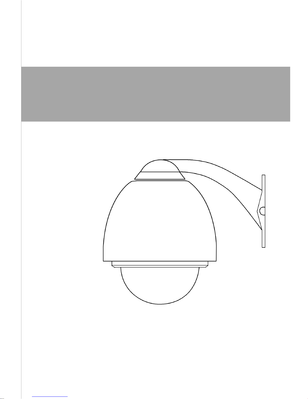
Installation/Operation Manual
for High Speed Dome Camera V1.2

SAFETY PRECAUTIONS
The lighting flash with a arrowhead symbol, in an equilateral triangle,
is intended to alert the user. There is uninsulated “dangerous volt-
age” presence near by the product’s enclosure which may be risk
of to persons.
The exclamation point within an equilateral triangle is intended to
alert the user to reference of the important operating and mainte-
nance (servicing) instructions.
RISK OF ELECTRIC
SHOCK. DO NOT OPEN!
CAUTION:
TO REDUCE THE RISK OF ELECTRICAL SHOCK, DO DOT
OPEN COVERS. NO USER SERVICEABLE PARTS INSIDE.
REFER SERVICING TO QUALIFIED SERVICE PERSONNEL
CAUTION
THE PRODUCT CODE MARKED ON THE BOTTOM COVER.
PLEASE FILL THE CODE IN THE FOLLOWING BLANK. PLEASE
SAVING THIS SPECIFICATION CAREFULLY, SO THAT CHECKING
MODEL:
PRODUCT CODE:
A
SAFETY
PRECAUTIONS

Important Safeguards
I. The Installation of the System
1. The Style of the Installation
2. Steps of Installation
II. The outlines description
III. Appendix I Lightning Proof and Surge Signal Proof
Appendix II The Cleaning of Clear Down Cover
Appendix
ⅢⅢ
ⅢⅢ
Ⅲ AC24V Wire diameter and transmission
distance comparison chart
Appendix
ⅣⅣ
ⅣⅣ
Ⅳ Wire Gauge Conversion Chart
INSTALLATION INDEX
1
2
2
3
7
9
9
10
11
Important Safeguards
I. Description of Functions
II. Setup of the Menu of the Dome Camera
III. Setup of the Dome Camera
1. Connection of the System
2. Setup of Coding Switch of Dome Camera
3. Setup of the Protocol and the Default Baud Rate
4. Setup of the Baud Rate of Communication
5. Selection of the Terminal Resistor of the Dome Camera
IV Technical data table
V Troubleshooting
VI Appendix
Ⅰ: RS485 Bus Basic Knowledge
OPERATION INDEX
12
13
16
27
27
28
29
30
30
31
33
34
34
B
INDEX

IMPORTANT SAFEGUARDS
1
IMPORTANT
SAFEGUARDS
1 All the safety and operating instruction should
be read before the units is operated.
2 The power supply for the dome:AC24V/1.
7A, Which is displayed on the bottom of the
pedestal or other place of the dome.
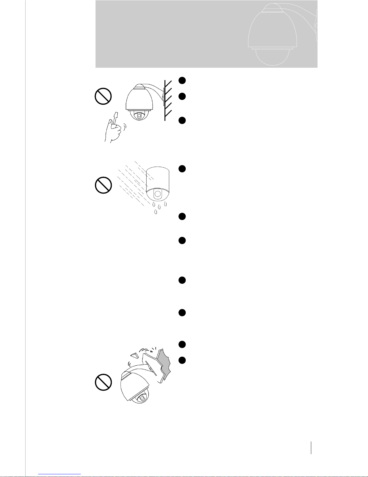
3 Do not attempt to disassemble the camera.
In order to prevent electric shock, do not remove screws or covers. There are no userserviceable parts inside.
4 The product should be indoor installed and
operated to avoid rain and moisture. Do not use
it in wet places. If outdoor installation is needed,
the closed protect cover should be used and it is
absolutely prohibited to use it in open air
independently.
5 Do not operate it in case temperature, humid-
ity and power supply are beyond the limited
stipulations.
6 Do not let the camera aim at the sun or the
object with extreme light whatsoever it is
switched on or not. Do not let the camera aim at
or monitor bright and standstill object for a long
time.
7 Do not use aggressive detergent to clean the
main body of the camera. Wipe dirt with dry
cloth. If needed, mild detergent can be used
suitably.
8 Operate the intelligent speed dome camera
with great care to avoid shock or vibration. It
operate incorrectly, the Speed Dome could be
damaged.
9 Please install the dome to the suitable place
for bearing enough capacity.
10
If necessary, use a commercial lens cleaning paper to clear the lens windows. Gently wipe
the lens window until clean.
※ We offer three-year guarantees on all
products,excepting the CCDS for one-year
guarnntee.
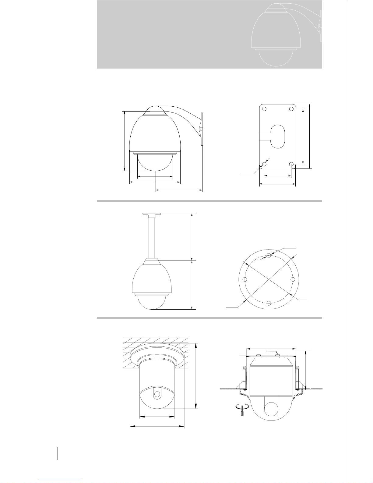
300
268
ø100
ø80
4-ø9
The Style of the Installation
a) Wall Installation
b) In-Ceiling Installation
c) Indoor Ceiling Installation d) Indoor Embedded Installation
2
The Installation of
the System
120
142
80
58
4-ø9
ø152
ø219
262
202.5
Figure 1
1
Figure 2
210
ø135
ø197
ø156
131
Direct
Figure 3 Figure 4
I. The Installation of the System
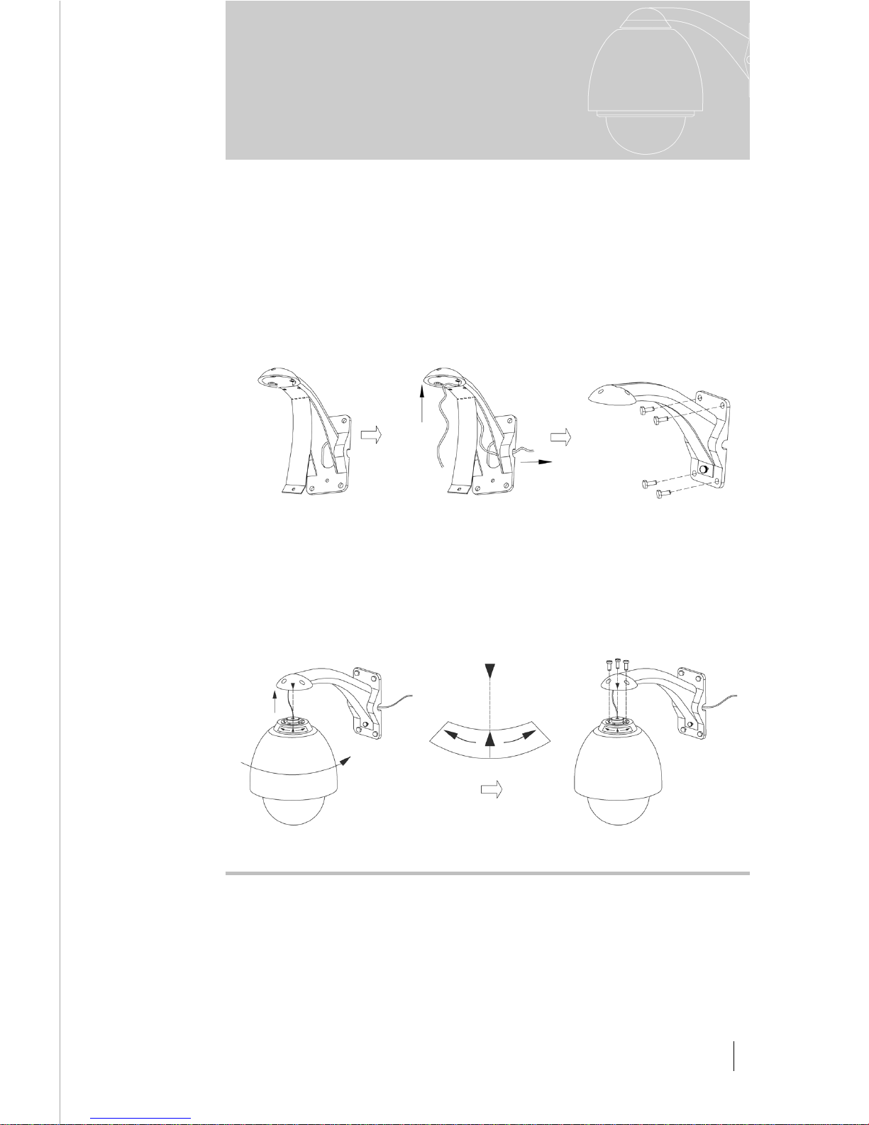
Figure 8 Figure 9
PUSH
LOCK
MARK
OPEN LOCK
Steps of Installation
a) Wall Installation
1) Unpacking the carton and carefully take out the dome camera and its
attachments.
2) Take out the cover of the wall-installed bracket.(Figure5).
3) Take out system control wires from the bracket(Figure 6).
4) Fix the bracket on the wall(Figure7).
5)Aiming the "MARK" of the bracket to the "MARK" of the flange, push the
dome upward to the end and rotate it with the direction of the arrow until it is
clicked and tightened.(Figure 8).
6) It's ok to fix the dome to the bracket with hexagon socket head cap screw
(Figure 9).
b) Steps of Installation for Indoor Ceiling Style
1) Unpacking the carton and carefully take out the dome camera and its
attachments .
2) Take out of the bracket, and fix the bracket on the wall.(Figure10).
3) Please connect the system control wires, video wires, power wires with the
3
The Installation of
the System
2
Figure 5 Figure 6 Figure 7
4
The Installation of
the System
bracket and go through it. Aiming the "MARK" of the bracket to the "MARK"
of the flange, push the dome upward to the end and rotate it with the direction
of the arrow until it is clicked and tightened(Figure11).
4) And then, please fix the dome to the bracket with bolts.(Figure12).
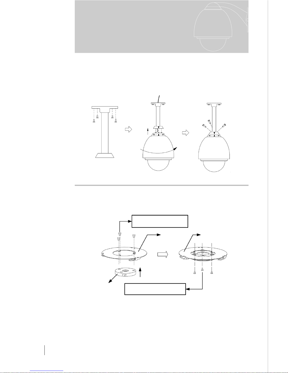
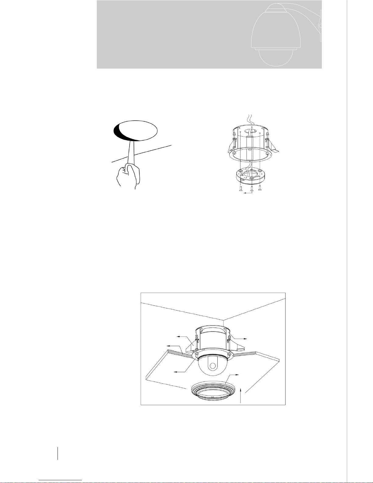
c) Steps of Installation for Indoor Ceiling Style.
1) Install the pedestal on the base plate(Figure13).
2) Fix the pedestal assembly on the ceiling (Figure14).
3) Aiming the "MARK" on the dome at the notch on the pedestal, push the
dome upward to the end and rotate clockwise until it is clicked(Figure15).
Figure 10 Figure 11 Figure 12
Figure 13 Figure 14
LOCK
Q3:M4 × 1.25”stainless steel
wood screw
Q6:M2.5 × 5 round head black
screw
A
D
B
5
The Installation of
the System
4) Put the decoration ring near the ceiling and rotate it clockwise until it is
tightened(Figure15).
5) (Figure 16) shows the system is installed.
6) The names of some parts are as follows:
A):Base Plate B): Pedestal C): Decoration Ring D):Pedestal Assembly
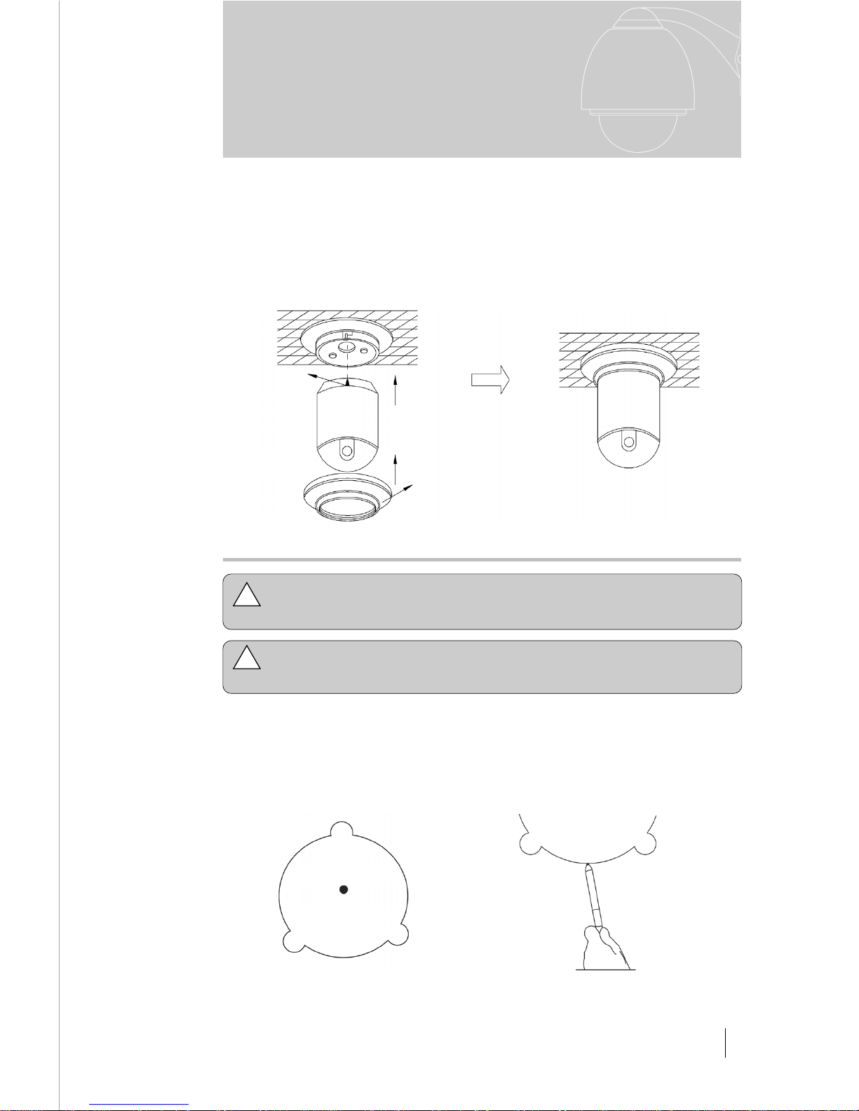
1) It has the drill map in embedded bracket,tip the black parts of double
paper, the central of drill map have a red spot, which is central spot
(Figure17).
2) Base on the red spot to draw the sign(Figure18).
MARK
Figure 15 Figure 16
Figure 17 Figure 18
d) Notice: The thickness of the ceiling to install speed dome
must be
≤≤
≤≤
≤ 1.65 inch (4.2 cm) and
≥≥
≥≥
≥ 0.38 inch (0. 8cm).
Notice: The ceiling should withstand 4 times the load of the
speed dome weight.
!
!
Decoration Ring
3) According the material of ceiling, choose the different tools to drill
(Figure19).
4) Fixup the "installation pedestal" with the embedded mount(Figure 20).
5) For easy installation, adjust the three swing mounting clips to let the
distance between the clips and the flange a little longer than ceiling thickness.
6) Swing the three mounting clips to adhere to back box wall. Place the back
box inside the ceiling hole. Let the flange cling to the ceiling.
7) Turn the three mounting clip bolts to let the mounting clips press the ceiling
and swing out gradually. The ceiling is clamped between the mounting clips
and the flange, thus the back box is secured above the ceiling.(Figure 21).
6
Figure 21
Figure 19 Figure 20
M4 × 12 countersunk head
screw(3pcs)
Indoor drop celing
installation bracket
Ceiling
Swing Mounting Clip
Decoration Ring
Flange
The Installation of
the System
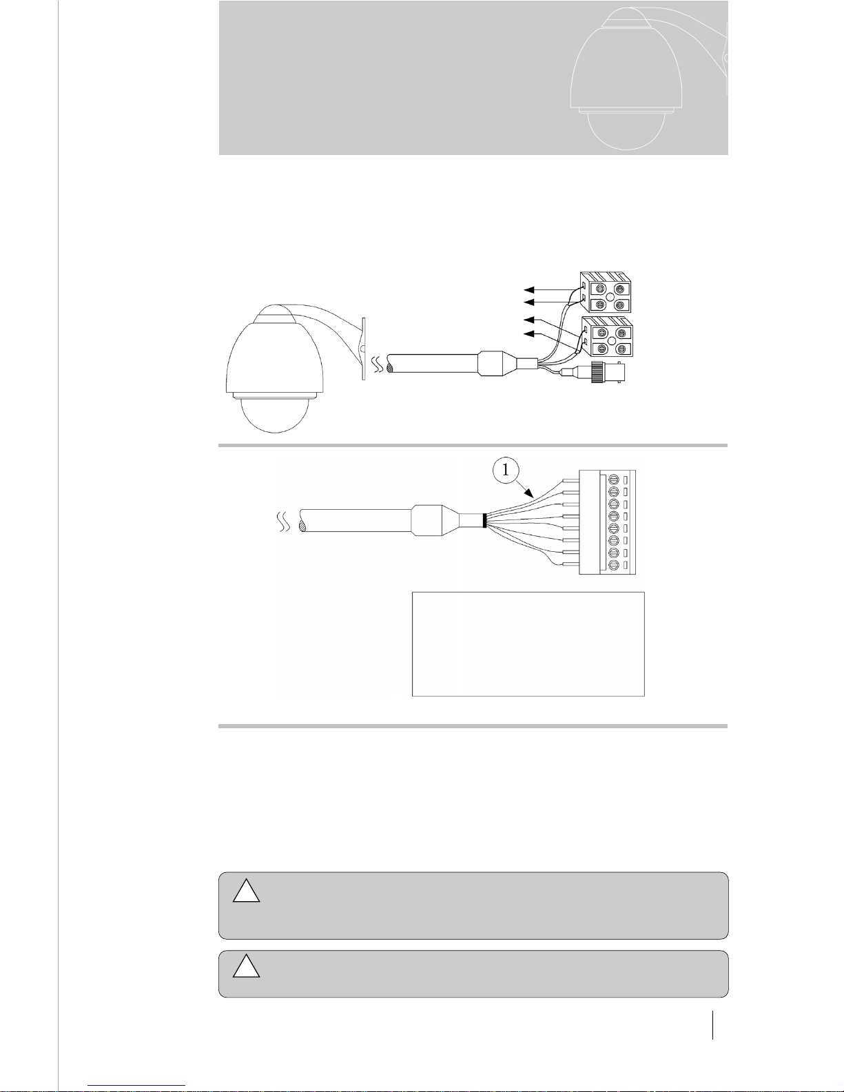
Figure 22
RED CONNECTOR
(POWER IN)
BLACK CONNECTOR
(RS485 CONTROL IN)
VIDEO OUT
RED LINE (AC24V IN)
BLACK LINE (AC24V IN)
ORANGE LINE (RS485+)
YELLOW LINE(RS485-)
RED1:
ORANGE2:
YELLOW3:
GREEN4:
BLACK5:
WHITE6:
BLUE7:
PINK8:
The synthetical wires as follows(Figure22),Orange isRS485+、
Yellow is RS485-;While you are using AC24V power line,the red and
black is the input side of the power ;BNC connector is the video-out side
(Take carefully while you connect these wires).
The description of Alarm out-line
(Figure23).
The o description of Alarm out-line.
According the fig of D3 to connection. As show of figure 24-1, when dome
identify the alarm signal, that will set according the program immediately,
then startup camera, switching the image of alarm field to main monitor.
Surveillance the alarm preset, then record it in time. Fig24-2 is connection
of alarm control.
II. The outlines description
7
Figure 23
1
2
3
!
Input of alarm: Input signal of switch type, any other input signal will
damage dome. When multi-channel with alarm signal, dome will
respond one by one, the removed time is two sec.
!
Once the dome have alarm input, dome will not respond“scanning”、
“patrol”、“remember tracking”etc function.
The outlines
description
ALARM-1 IN
ALARM-2 IN
ALARM-3 IN
ALARM-4 IN
ALM IN COM
ALARM OUT COM
ALARM NO OUT
ALARM NC OUT
 Loading...