

Page 1

DVRSHD Series
DVR04SHD/08SHD/16SHD
www.mdh-system.pl
User Manual
The picture might differ according to the specifications.
This User Manual is based on DVR16SHD.
1997-2005
Contents of this user manual are protected under copyrights and computer program laws.
First Edition: November 1, 2005
Thank You
Page 2

Thank you for choosing our Digital Video Recorder.
Before operating the system, please read this User’s Manual thoroughly and retain it for future reference.
WARNING
TO
REDUCE FIRE OR SHOCK HAZARD, DO NOT EXPOSE
THE UNIT TO RAIN OR MOISTURE.
This installation should be made by a qualified service person and should
conform to all local codes.
Page 3

Page 4

Cautions
Read Before System Operation
Follow these details to prevent material damage or personal injury.
Signs of Caution and Warning
Warning: This sign indicates that the user could die or be seriously wounded if not used or installed
properly.
Caution: This sign indicates that the user could be wounded or could expect property damage if not
used or installed properly.
Warning: Do not expose the product to fog, rain or too much humid to decrease danger from electric shock
or fire.
Important Safeguards
Warning
1. Change the battery after turning the off the power of the product.
2. Check the polarity of the lithium battery while changing.
3. Change the battery with the same one, which is in the product or with the similar type recommended by your vendor.
4. Dispose of the changed battery according to the instructions of the battery manufacturer.
There is danger of explosion when instructions are not followed.
General Warning
Warning
1. Use the power cord, which is supplied or recommended by the supplier.
It may cause fire.
2. Do not dismantle or assemble the product.
It may cause malfunction or fire.
3. Enquire from your vendor for repair.
It may cause electric shock or fire if the repair is not done properly.
4. Do not touch the product with wet hands.
It may cause malfunction or electric shock.
5. Matters must be ensured to a professional for product installation.
It may cause malfunction, electric shock or fire.
6. Consult the place of purchase if the need for installation arises.
Delinquent installation may be the reason for malfunction, electric shock or fire.
7. Ground applies to video products equipped with a 3-wire grounding type plug having a third (grounding) pin.
This plug only fits into a grounding-type power outlet.
If grounding is not done, it may cause malfunction or electric shock.
8. Ground connection must not touch gas pipe, water pipe or telephone line.
If grounding is not done properly, it may cause electric shock.
9. Prevent metallic foreign substance from going inside the product.
It may cause malfunction or electric shock.
10. Do not spray insecticide or flammable spray while driving.
It may cause fire.
11. Prevent water from entering inside electrical parts.
Clean with a dry towel or malfunction or electric shock could result.
Page 5

Caution
1. Use the power cord, which is supplied or recommended by the supplier.
The internal fan rotates at high speed and may cause an accident.
2. Do not drop, give strong vibration, or shock to the product.
It may cause malfunction.
3. The air inhaler of the front panel and air outlet of the back panel must not be blocked during installation.
The internal temperature of the product would be greater than allowable and could cause malfunction or
fire.
4. Do not touch the product or the power cord when there is thunder.
It may cause electric shock.
5. Do not install the product near or on top of heating source.
The internal temperature of the product would be greater than allowable and could cause malfunction or
fire.
6. Do not install the product on inclined or unstable location or where vibration could be committed.
It may cause malfunction.
Cautions about the Power
Warning
1. Must use the outlet of the grounding to connect the power cord.
It may cause fire.
2. Do not connect on the middle of power cord or use extension cord.
It may generate heat or cause fire.
3. Do not touch the power cord with wet hands.
It may cause electric shock.
4. Keep power cord dry and protect from humidity.
It may generate heat or cause fire. The power cord is not waterproof.
5. Hold the body of the plug while removing the power plug.
Do not pull the power cord. Damage to the power cord may generate heat or cause fire.
6. Check the power plug regularly.
Humidity and moderation in smoking may cause fire.
7. Remove power cord from outlet when product is not used for a long time.
It may cause short-circuit or electric shock.
Caution
1. Do not turn off the power by removal of the power plug.
To turn off the power, click the power button from the front panel.
When the system stops abnormally, the power button might not work. Click power button for 5 full seconds to turn
power off.
2. Do not cut off the power artificially, or give shock or vibration to unit while the hard disk is activating.
It may cause hard disk failure or loss of data.
Page 6

Page 7

Category
1. SYSTEM STRUCTURE AND INSTALLATION.................................................................................................................... 1
2. EXPLANATIONS FOR EACH FUNCTION........................................................................................................................... 2
2.1 F
RONT PANEL
.......................................................................................................................................................................... 2
2.2 IR R
EMOTE CONTROLLER
....................................................................................................................................................... 5
2.3 R
EAR PANEL
............................................................................................................................................................................ 8
3. INSTALLATION.......................................................................................................................................................................11
3.1 C
ONNECTING PERIPHERAL DEVICE
........................................................................................................................................11
3.2 S
YSTEM STARTUP AND SHUTDOWN
....................................................................................................................................... 12
4. OPERATION........................................................................................................................................................................... 14
4.1 L
OG IN
................................................................................................................................................................................... 14
4.2 R
EAL TIME LIVE MODE
......................................................................................................................................................... 15
4.3 R
ECORDING IMAGE PLAYBACK MODE
.................................................................................................................................. 16
4.4 S
EARCH RECORDING IMAGE
.................................................................................................................................................. 17
5. SETTING................................................................................................................................................................................. 20
5.1 S
YSTEM - GENERAL
............................................................................................................................................................... 22
5.2 S
YSTEM - TIME & DATE
......................................................................................................................................................... 26
5.3 S
YSTEM - PASSWORDS
........................................................................................................................................................... 28
5.4 S
YSTEM – IMPORT/EXPORT SETUP
......................................................................................................................................... 30
5.5 S
YSTEM - LOG OFF
................................................................................................................................................................ 32
5.6 C
AMERA - RECORDING
.......................................................................................................................................................... 33
5.7 C
AMERA - SCHEDULE
............................................................................................................................................................ 36
5.8 C
AMERA - TITLE & SECURITY
............................................................................................................................................... 38
5.9 C
AMERA - COLOR
.................................................................................................................................................................. 41
5.10 C
AMERA -
PTZ...................................................................................................................................................................... 43
5.11 C
AMERA - AUDIO
.................................................................................................................................................................. 44
5.12 A
LARM - ALARM IN/OUT
....................................................................................................................................................... 45
5.13 A
LARM - MOTION ALARM
..................................................................................................................................................... 47
5.14 A
LARM - VIDEO LOSS
............................................................................................................................................................ 48
5.15 A
LARM – MISCELLANEOUS ALARM
...................................................................................................................................... 49
5.16 N
ETWORK - IP SETTING
......................................................................................................................................................... 50
5.17 N
ETWORK - DYNAMIC IP SERVER
.......................................................................................................................................... 52
5.18 N
ETWORK-EVENT NOTIFICATION
.......................................................................................................................................... 64
5.19 T
OOLS-SYSTEM INFORMATION
.............................................................................................................................................. 65
5.20 T
OOLS - SYSTEM LOG
............................................................................................................................................................ 67
5.21 T
OOLS - BACKUP
................................................................................................................................................................... 68
5.22 T
OOLS - SYSTEM UPGRADE
................................................................................................................................................... 71
5.23 T
OOLS-DISK FORMAT
............................................................................................................................................................ 72
5.24 T
OOLS - FACTORY DEFAULT
.................................................................................................................................................. 73
6. REMOTE SETTING.............................................................................................................................................................. 74
6.1 R
EMOTE SYSTEM SETTING
.................................................................................................................................................... 74
6.2 R
EMOTE MONITORING
.......................................................................................................................................................... 75
Page 8
1
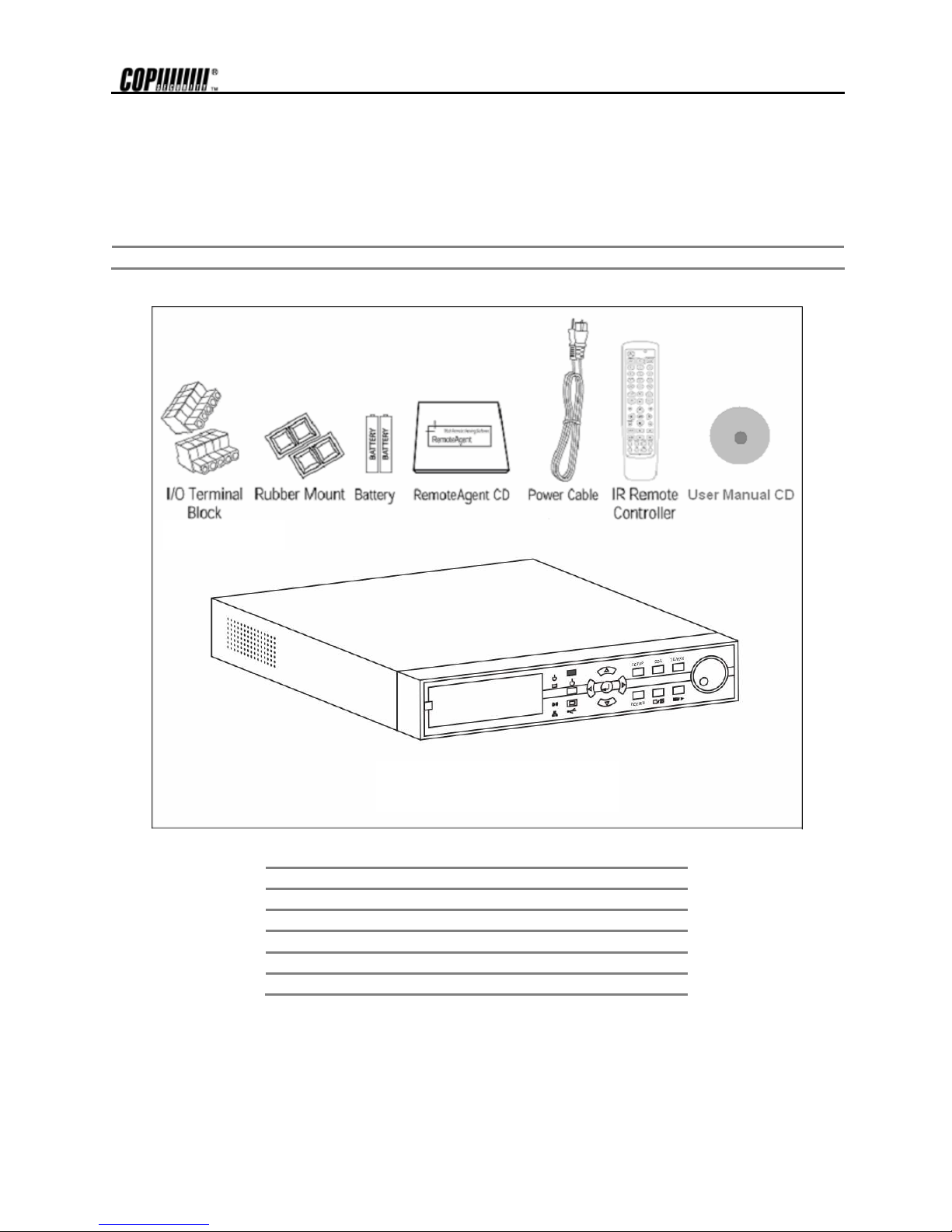
1. System Structure and Installation
The following accessories are supplied with the DVRSHD series digital video recorder. Keep the packing utilities for
moving or storage purposes afterwards.
Note
If any of these items is missing or damaged, notify your vendor immediately.
Qty Accessories
1 User Manual + RemoteAgent CD
1 IR Remote Controller
1 Power cable
4 Rubber Mount
2 I/O Terminal Block
DVRSHD Series
(DVRSHD16)
Page 9
2
2. Explanations for each function
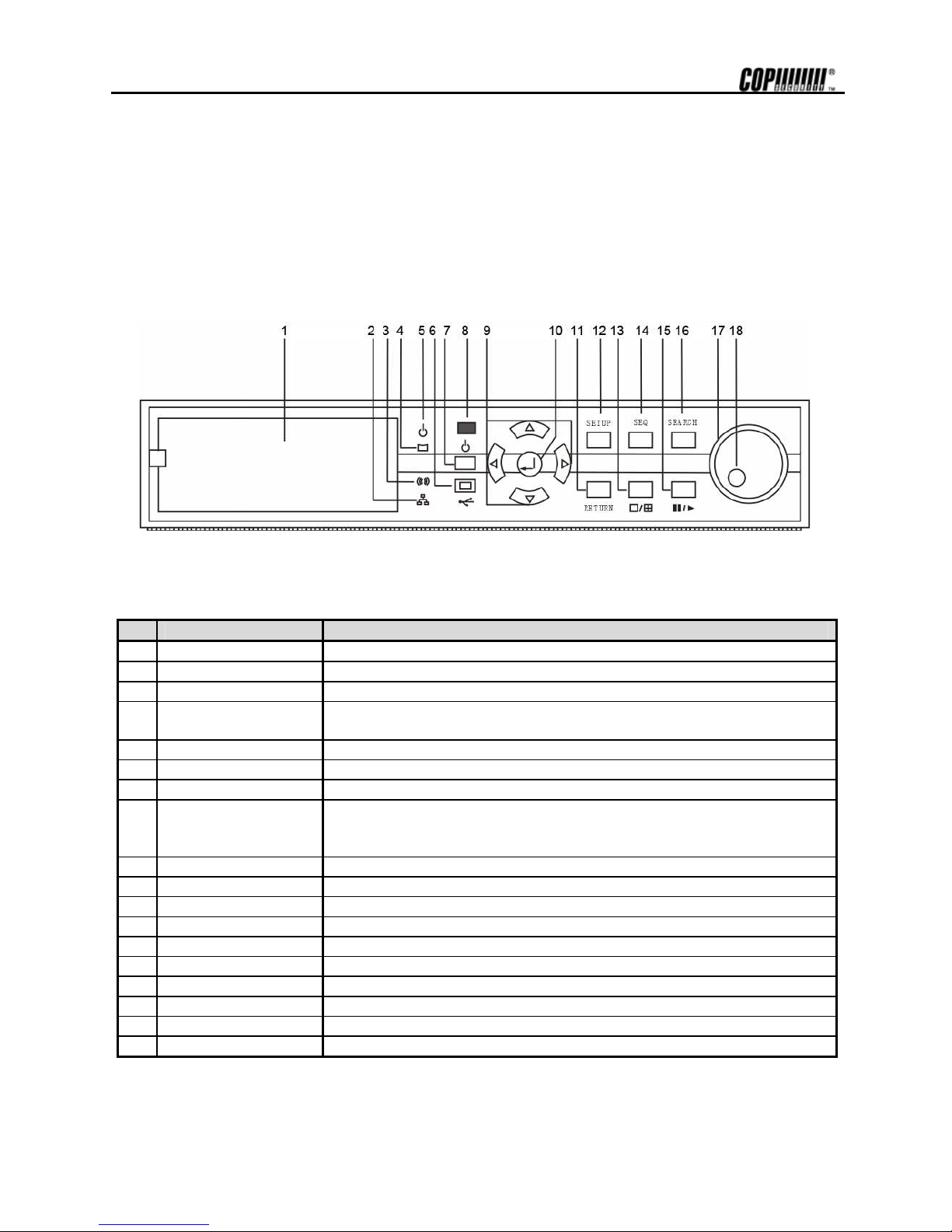
2.1 Front Panel
The buttons on both the front panel of the DVRSHD Series and IR Remote Controller have the same functions. Each
button can activate different functions. The buttons on the front panel of DVRSHD Series may be different in shape with
the remote controller buttons, but the IR Remote Controller can also control most of the functions controlled by the front
panel of the DVRSHD Series.
No. Buttons Functions
1 CD-RW Backup the recording image by internal CD-RW. (Option)
2 Network LED LED is lit while the network client(s) (RemoteAgent) is connected to the system.
3 Alarm LED LED is lit when the sensor signal is inputted to the connected system.
4 HDD LED
Shows if the camera image is being stored into or retrieved from the HDD (Hard
Disk Drive).
5 Power LED Shows Power On/Off status of the system (GREEN: Working, RED: Stand-by).
6 USB Port USB interface Port to connect to external storage equipment.
7 Power Button Receives input signal of the Remote Controller
8
Remote Control
Receiver
The channel image will change when the corresponding up, down, left and right
button is pressed. This is same as using cursor key (direction key) on the main
screen.
9 Select Channel Use to turn the Power On/Off.
10 ENTER Button Use to enter detail menu, go into the next stage, and select or set value.
11 RETURN Button Use to exit from the setting menu or to cancel setting value.
12 SETUP Menu to set user environment of the system.
13 Screen Mode Selection
Select the screen mode from 1, 4, 8 and PIP screen.
14 SEQ Button Automatic time sequencing for monitor images.
15 Playback / Pause Playback recorded images/pause.
16 SEARCH Search recorded images
17 Shuttle Shuttle (outer dial): Speed up the playback speed of the image (2~32X).
18 Jog Jog (inner dial): playback frame by frame.
Page 10

3
2.1.1. CD-RW (Option)
The DVRSHD series system can select the CD-RW as Option. Use the CD-RW to backup the recorded image. Refer to
“Image Backup” for detail explanation.
2.1.2. Network LED
LED is blue when the system is connected to any network client (RemoteAgent). Light is automatically out when all clients
are disconnected.
2.1.3. Alarm LED
LED is lit if the system’s connected Alarm activates.
2.1.4. HDD LED
LED is blue when the camera image is being stored into or retrieved from the HDD. So, even though the system is
continuously recording, the HDD LED is only lit when actual data is recorded in the HDD. Usually, the LED will be flickering,
and this is normal.
2.1.5. Power LED
LED to show the power input and status of the system. The LED is red when the system is in stand-by position, but is
green when the system is working and power is being supplied.
2.1.6. USB Port
Use to backup recorded images of the DVRSHD series by using USB storage device. System software upgrade is
possible with USB storage device.
2.1.7. Power Button
Connect the power cable of the product before pressing this button to turn the power on and off.
2.1.8. Remote Controller Receiver
DVRSHD can be operated conveniently, using the remote controller. Receives input signal from the remote controller
2.1.9. Select Channel
These buttons are used to change the channel images. Left/Right button is used to change the channel on 1- screen
mode or PIP mode and Up/Down button is used to change PIP channel from PIP mode. Also, these buttons are used to
move cursor in “Setting” mode as up, down, left, or right, and also used to increase or decrease the setting value.
2.1.10. ENTER Button
The [Enter] button is used to go to the next stage, select value or settings.
2.1.11. RETURN Button
Use to cancel the password just typed at the setting menu or return to previous menu.
2.1.12. SETUP
Set the environment of the DVRSHD system according to the user requirement. Refer to “Setting” for detailed
explanation.
2.1.13. Screen Mode Selection
Screen mode can be selected from the monitor screen. Whenever the buttons is pressed, it will change in sequence in 1, 4, 8, 16 and
PIP screen.
Page 11

4
2.1.14. SEQ Button
Press SEQ Button and the screen will automatically changes. Refer to “Settings” for automatic sequencing interval.
2.1.15. Playback / Pause
Playback recorded screen. The corresponding channel can be playback in 1 screen mode and all the channels can be playback in 4, 8 or 16
channels at once.
2.1.16. SEARCH
Search the recorded image by date and time. Refer to “Recording Image Playback Mode” for detailed image searching
method.
2.1.17. Shuttle
Jog/Shuttle dial is used to playback recording images. The inner dial is called Jog and the outer dial is called Shuttle. The
Jog/Shuttle dial has two kinds of functions. The Shuttle is used to speed up the playback speed of images by clockwise or
anti-clockwise. Playback speed is indicated as x2, x4, x8, x16, and x32 on the lower end of the screen.
2.1.18. Jog
The Jog is used to find the recording image frame by frame. Turn the Jog dial clockwise or anti-clockwise (only I-Frame is
playback during anti-clockwise) to see the image frame by frame during pause state.
Page 12
5
2.2 IR Remote Controller
The function buttons of the IR Remote Controller are the same functions as function buttons on the front panel as shown
below.
No. Functions
1 Activating LED
2 Power Button
3
SETUP (Use the Preset Button while using the
PTZ )
4 PTZ
5
Screen Mode Selection (1 / 4 / 8 / 16 / PIP screen
sequence button)
6 Number Input Button
7 Digital Zoom Button
8
ZOOM IN (enlarge) /ZOOM OUT (decrease)
9 IRIS+ (Open) / IRIS – (Close)
10 FOCUS NEAR / FAR
11 Direction Key
Page 13
6
12
RETURN
(Use the 4 diagonal direction key button while using
the PTZ)
13 SEARCH Button
14 Playback Backwards Frame by Frame
15 Playback Forward Frame by Frame
16 Playback/ Pause Button
17 Fast Playback Forward Button
18 Fast Playback Backwards Button
19 EVENT Button
20 BACKUP Button
21 F/O/E Button
22 RETURN
23 OSD Button
24 SEQ Button
25 F1 (Use to enter ID)
26 F2 (Use to enter ID)
Note F/O/E Button (use only on remote controller)
The object in the recorded image might show the feathering effect during frame playback because images at
720x480(PAL:720×576) resolution have higher vertical resolution than 720x240(PAL:720×288) or 352×240
(PAL:352×288). The feathering of the image can be solved when only one of two Fields (Odd, Even Field) is
selected. Default is frame playback. When the button is pressed, it will change to Odd Field Playback-> Even
Field Playback-> Frame Playback order.
Note To use the IR Remote Controller, set the initial ID to be as same as the ID in SETUP->SYSTEM->GENERAL->IR
REMOTE CONTROLLER. The user requires setting the ID only once. Refer to the next page for detailed information
about ID input.
Page 14
7
Note Number Button
Change the channel on 1-screen mode. Press the number buttons for 1~4 channels to see the corresponding
channels. It is also use to set the setting value on the “Setup” menu.
Direction Key Button
The direction key activates differently for Real-time Image/Playback Mode, Setup Menu Mode, Search Menu
Mode and Digital Zoom Mode. The Digital Zoom Mode only activates in Real-time Image Mode, Recording
Image Playback Mode and 1-screen mode. Thus change the screen to 1-
screen mode to activate direction key.
On Real-time Image/Playback Mode On Digital Zoom Mode
Right Side Direction Key: Increase the channel on
screen
Up, Down, Left, Right Button: To Move Direction
Left Side Direction Key: Decrease the channel on
screen
Enter ( ) Button: PIP Screen On/Off
Up Side Direction Key Button: Increase PIP channel
on PIP Mode.
Zoom In/Out Button: To Decrease or Enlarge
Screen
Down Side Direction Button: Decrease PIP channel
on PIP Mode
Diagonal Direction Button: Return
Setup Menu, Search Menu Mode PTZ Mode
Up, Down, Left, Right Button: To Move direction Up, Down, Left, Right Button: To Move Direction
Diagonal Direction Button: Return Diagonal Direction Button: To move Direction
2.2.1. Setting IR Remote Controller
As one IR Remote Controller can control several product, ID will have to designated to use each Remote Controller on
each product.
The following below is the method to set the ID of IR Remote Controller. Default ID will be 00.
1. Insert the battery into the IR Remote Controller (AAA Size×2).
2. Press both [F1] Button and [F2] Button at once on the IR Remote Controller for more than 2 seconds.
3. Check whether LED of the IR Remote Controller is lit.
4. By using the IR Remote Controller’s number button, set the ID number from between 00~99. Set the ID
number in 2 digits (ex. 03,55).
5. Set the ID of the system as same as the number set on the IR Remote Controller, by using front panel direction
key.
6. Press [OK] Button on the screen to save the set ID.
Note
All the System had same default value ID when it is out from the factory. Therefore, when the default value is
used, one IR Remote Controller can control several systems at once. To prevent this, it is recommendable to
set each ID for each system. As it is easy to change the ID for IR Remote Controller, several systems can be
controlled separately by changing the ID of the Remote Controller whenever it is used.
Page 15
8
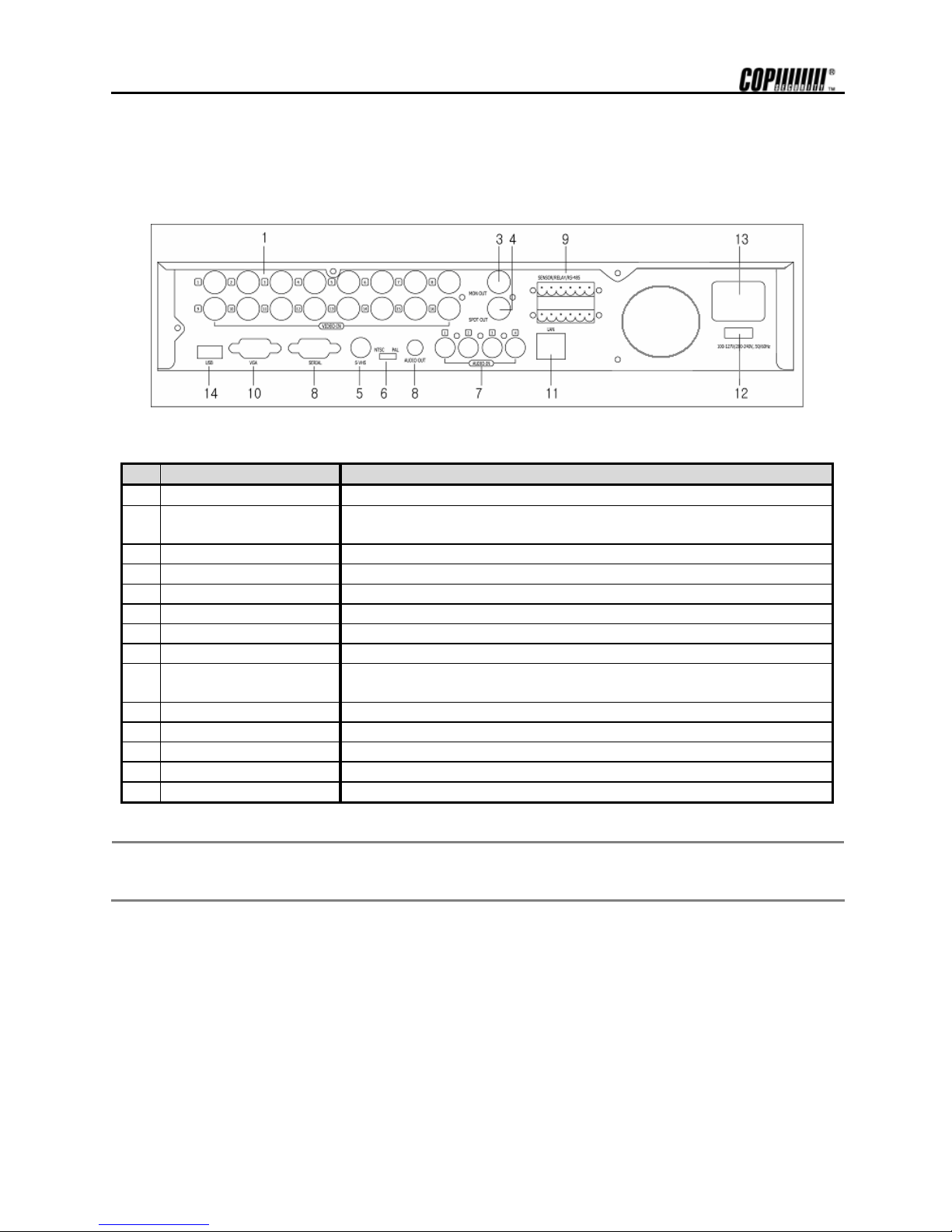
2.3 Rear Panel
The following is the rear panel of the DVRSHD series system.
[DVR16SHA]
No. Name Description
1
VIDEO-IN (BNC) Connect camera. (Supports NTSC/PAL)
2
LOOP-OUT
Camera images of each channel will be outputted as is. Also, used when the
corresponding image is required for other product (8 /16 channel has no LOOP-OUT).
3
MON-OUT Connect to the main monitor for camera image for surveillance/management/playback.
4
SPOT-OUT Use to output the entire surveillance screen one by one, in an interval.
5
S-VIDEO Connect to S-Video input terminal to output image of the main monitor.
6
Select NTSC / PAL Select the signal system. (NTSC / PAL)
7
AUDIO IN Connect Audio Input Device. (with Amp.)
8
AUDIO OUT Connect Audio Output Device. (with Amp.)
9
ALARM/ SENSOR /RS-485 Terminal to connect external input sensor of 1~4 channel. (Supports N/O or N/C)
Connect RS-485 signal output or relay for P/T/Z camera control.
10 VGA Port Connect to PC Monitor.
11 LAN Port 10/100 Ethernet connection terminals for remote connection.
12 Power Input
Power cable connection terminal for connecting to main power.
13 Power Switch
Switch to change input power. (115/230V)
14 USB Port USB interface Port to connect to external storage equipment.
Note
Check whether the specification of the peripheral devices connecting to the DVRSHD series matches with the
specification supported by DVRSHD series system. Enquire from your vendor for detail explanations. For
Audio input/output, use the product with amp attached.
Page 16

9
2.3.1. VIDEO-IN
Connect the BNC plug of the camera cable to the corresponding channel number’s image input BNC plate, which is on
the rear panel.
Note Camera Input voltage level is 1Vp-p±10%.
2.3.2. LOOP OUT
Use to apply the video of camera input to other device. Without using a video distributor, the same image can be connected to the
camera input of other product. (Not applicable for DVR08SHA/16SHA)
2.3.3. MON OUT
Connect the BNC cable of the monitor to MON OUT BNC cable of the rear panel. The monitor is use for surveillance on the image
shown and to manage system or playback recording image. .
2.3.4. SPOT OUT
The spot monitor can only be used to display input images in automatic interval mode. Refer to “Settings” for automatic interval time
setting of spot monitor.
2.3.5. S-Video Output
One additional main monitor can be installed by using the S-Video output. Use the S-Video cable to connect the DVRSHD with the
monitor, which has S-Video Input.
2.3.6. Select NTSC / PAL
Turn off the power of the DVRSHD series and select the NTSC/PAL switch correctly. Then turn on the power again.
2.3.7. Audio In
Connect Audio Input Device.
Note Input voltage of audio input device is line level.
Use of audio output device with amplifier is recommended.
2.3.8. Audio Out
Connect Audio Output Device
Note Use of audio output device with an amplifier is recommended
2.3.9. ALARM/SENSOR/RS-485
Connect sensor (dry contact type). Separate the terminal block and wire all devices to desired pins, before connecting the terminal block
again. Connect each ground (GND) line to “G” pins.
Note Support both N/O (Normal Open) and N/C (Normal Close). If connected sensor is not functioning, ensure wiring is
correct.
Connect various alarm devices controlled by relay output. DVRSHD series supports RS-485 for P/T/Z control.
Page 17
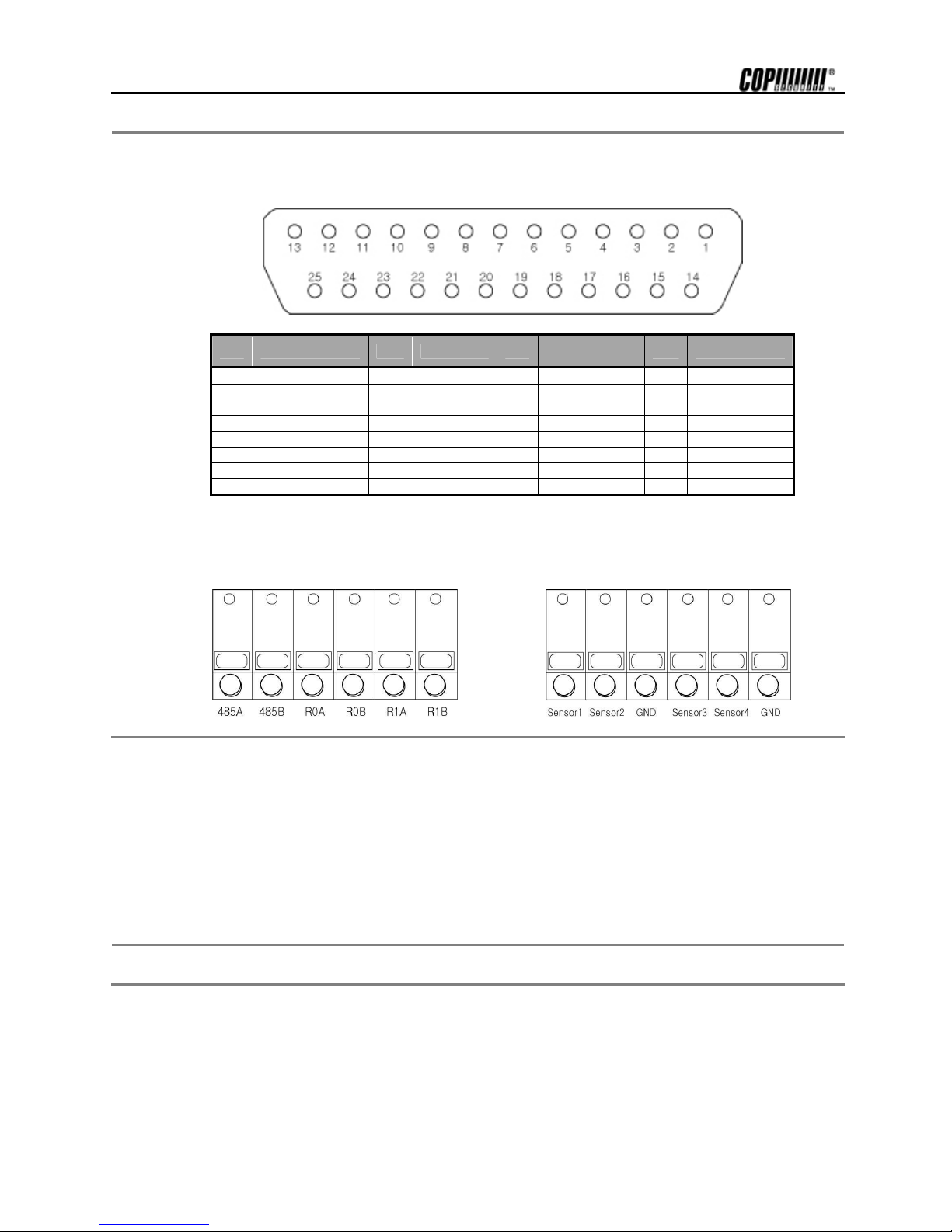
10
Note
The connection method differs according to the type of P/T/Z controller use. Enquire from your vendor incase you
are using other than RS-485.
Refer to picture below for printer port connection of the DVR04SHA & DVR08SHA series rear panel.
NO. SENSOR NO. RELAY NO.
Serial
Communication
NO. NO Connect
1 SENSOR1 5 RELAY1(+)
8 RS485-RX
9 NO Connect
2 SENSOR2 6 RELAY2(+)
20 RS485-TX
10 NO Connect
3 SENSOR3 7 GND
22 RS232-TX
11 NO Connect
4 SENSOR4 13 GND
24 RS232-RX
12 NO Connect
14 SENSOR1-GND 18 RELAY1(-) 23 NO Connect
15 SENSOR2-GND 19 RELAY2(-) 25 NO Connect
16 SENSOR3-GND 21 GND
17 SENSOR4-GND
Refer to the picture below to connect [I/O Terminal Block] to the Alarm/Sensor/RS485 port of the DVR16SHA system’s back
panel.
First connect RS485~R1B to the top and Sensor1~GND to the bottom.
[Top of I/O Terminal Block] [Bottom of I/O Terminal Block]
2.3.10. VGA Port
See the image by connecting with normal PC Monitor.
2.3.11. LAN Port
Connect RJ-45 jack of LAN cable to LAN port. Network has to be TCP/IP base 10/100 Ethernet LAN (Local Area Network), Internet
or exclusive line, and IP address should be fixed one. Consult network administrator for proper network configuration.
2.3.12. Power Input
Connect to main power cord of the system.
Caution Before plugging-in the power cord to the system, check if the power is in accordance with the system specification
(Single Phase AC 115/230V)
2.3.13. Input Power Switch
Input power can be used, by selecting according to the user environment. Check input power before inputting power.
2.3.14. Port
Use the USB device to backup the saved image of the DVRSHD system. S/W upgrade can be also done using USB device.
Page 18
11
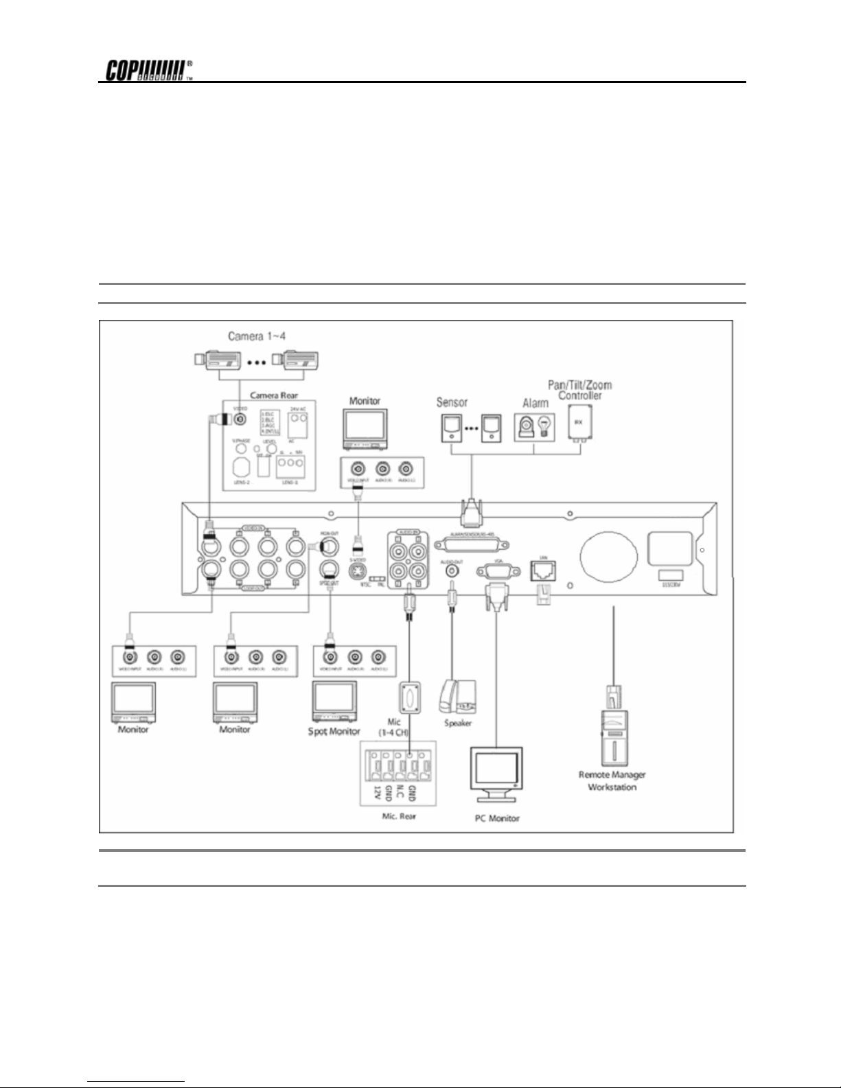
3. Installation
3.1 Connecting Peripheral Device
This section describes how to efficiently hook up peripheral devices using with the DVRSHD series. Below picture shows
connection of the DVRSHD series with the peripheral devices.
Install the DVRSHD series on flat surface. If required, attach a rubber mount for installation. Incase 19-inch rack is used, it is
recommend to install the system on shelve and use 2.5~3U(1U=1.75 inch or 4.45 cm) space for proper ventilation.
Note
Install the system in location with good ventilation to prevent overheating.
Caution Depending on the grounding, the coaxial cable connecting to the camera has danger of electric shock. Shut down
power of the system completely (unplug the power cable) before connecting video cable to BNC port.
Page 19
12
3.2 System Startup and Shutdown
3.2.1. System Startup
After connecting all peripheral devices, connect power cord to DVRSHD series for system startup. The power will turn on
automatically if there was abnormal shutdown, such as power failure.
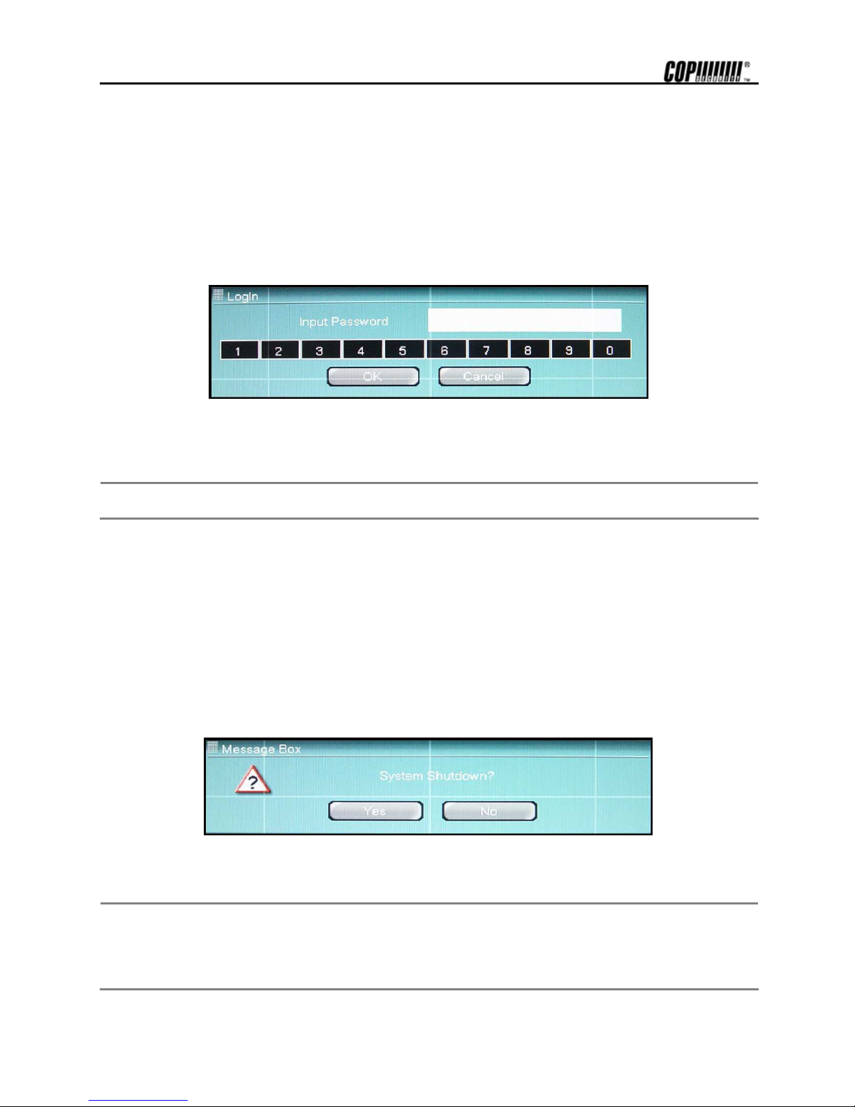
Register admin password after inputting power and turning on the system. This is to prevent others from using. Incase password is not
required, press [OK] without entering password.
Enter the Password and press [OK] button. Next re-enter once again.
Caution
Do not forgetting the administrator’s password, which had been set for the first time. In case, the password
is forgotten, enquire from your vendor.
A screen asking for admin password will appear when the system power is turned on for the first time. Then, Log In
screen will appear. Next step will be proceeding right away without Log In process, in case there is no admin password.
Several users can use one system, using different password. Refer to “System->Password” part for user setting method.
3.2.2. System Shutdown
To turn the power off, press the power button for proper shutdown of the system. Do not pull off the power by pulling the
power plug.
The below message will appear when the [Power] button is pressed to shutdown the system.
Press [Yes] button and confirmation admin password will appear. Enter the proper password and press [OK] button to
shutdown the system safely.
Note Incase the power plug has been plug off to turn off the power while the system is activating, the files will not be closed
properly. Therefore, when the power plug is plug to turn off the power, the index information for efficient search for
corresponding file will not be saved even though recorded image is not damaged (Journaling File System).
The power button had to be used to turn off the power, so that the system can be used right away after booting and to
prevent product defect.
3.2.3. Countermeasures after abnormal shutdown
DVRSHD series have been designed to operate for long period without a problem.
Page 20

13
The operation of the system can be locked up however, when major parts (such as hard disk) function abnormally due to external
electric shock, physical damage, or other various reasons.
The system stops operating during abnormal situations, and the internal watchdog circuit is activated in order to reset the system for
rebooting within 2 minutes. The system will then recover normally. It will also automatically reboot even when there is power failure.
However, if major parts (such as hard disk) are physically damaged, it is impossible to recover normally. This will cause continuous
rebooting by watchdog or deadlock without reset.
Countermeasures for abnormal discontinuation are as follows.
1. In case the power cannot be turned off, turn off by pulling the power cord.
2. Wait for about 10 seconds and reconnect the power. Ensure the system is functioning properly.
3. Consult your dealer if system is not functioning properly after reconnecting power.
Page 21
14
4. Operation
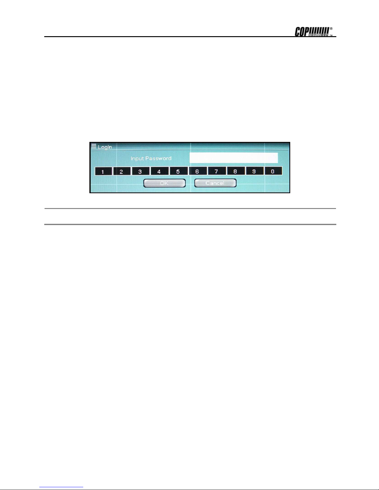
4.1 Log In
Check the power connection. The system can be used after power-on.
DVRSHD series have various setting categories. The administrator can set the system password and <User> to prevent unauthorized
changes to setting values and alteration to record file.
Enter the <Admin> or <User> password which had been set. In case the <Admin> and <User> password is same, it will
recognize as <Admin>.
Note
Do not forgetting the administrator’s password, which had been set for the first time. In case, the password is
forgotten, enquire from your vendor.
Page 22
15
4.2 Real time Live Mode
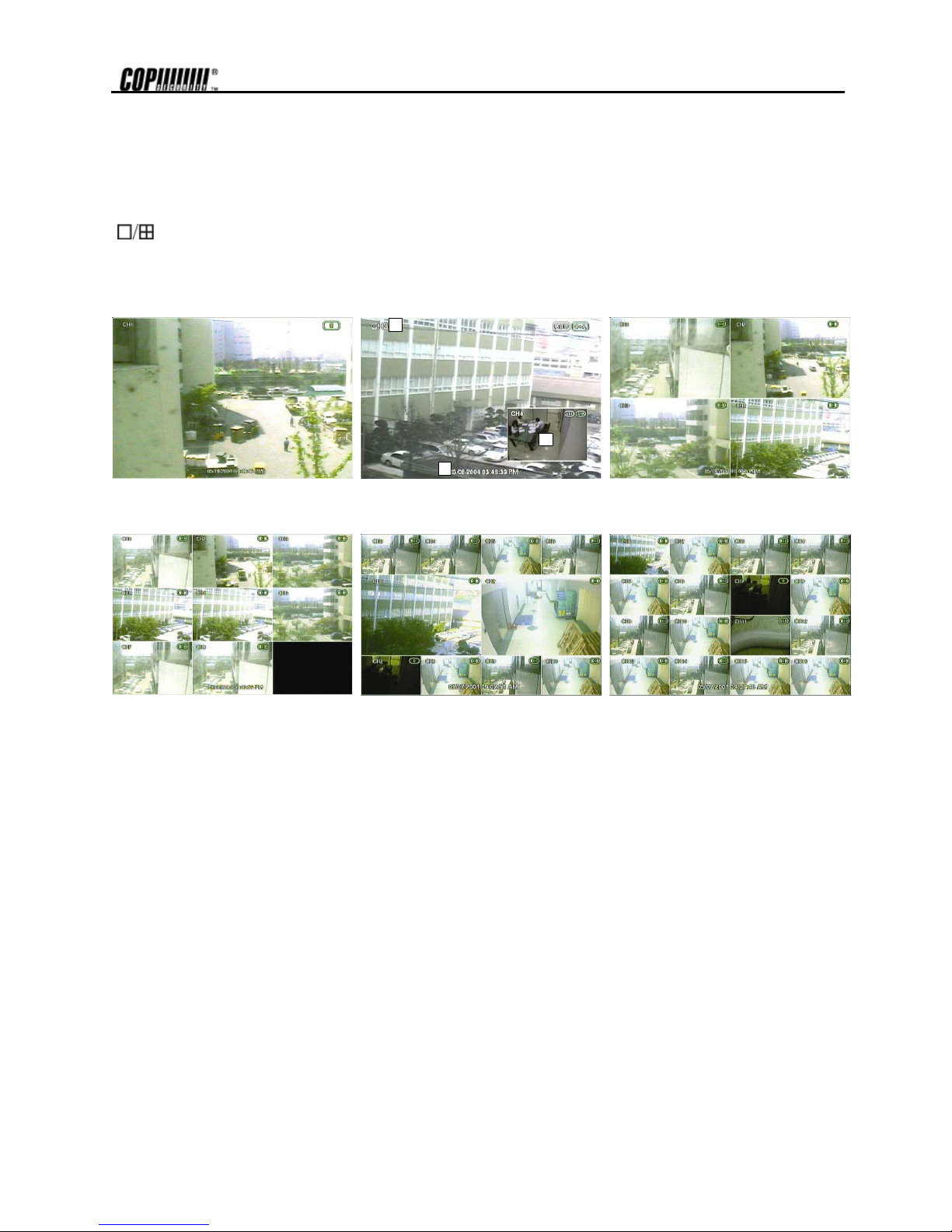
Real time live image can be seen by easy button operation after inputting power.
The images can be seen Real-time by 1, 4, 9, 10, 16 and PIP screen. Whenever the button on the front panel or IR remote controller
[ ] is pressed, the screen will change in 1 -> PIP -> 4 -> 9 -> 10-> 16 channels in sequence. To change the channel from 1
screen mode, press the left/right arrow button on the front panel or IR remote controller.
4.2.1. Screen Configuration
1111
2222
3333
[1 Screen] [PIP Screen] [4 Screen]
Above is typical screen with displayed items. Press [OSD] button on the front panel or IR Remote Controller to control the
display of OSD. Whenever the button is pressed, the display of OSD will toggle between appearance and disappearance.
The following is the explanation of each item displayed on the screen.
1. Channel Name: Shows camera title of the location. Refer to “Setup->Camera->Title&Security” to input camera
location.
2. Date and Time: Indicates present date and time of the system. When the recorded data is playback, it indicates
date and time of the recorded time displayed.
3. PIP : PIP screen will be indicated as one of the multiple screens and it also appears when digital zoom is used
in full screen mode. Digital zoom is used to enlarge or decrease screen image and the digital zoom button of
the remote controller is used.
Page 23
16
4.3 Recording Image Playback Mode
For the user to search recording image of the DVRSHD series, the user will require selecting the date and time to search
recording data easily.
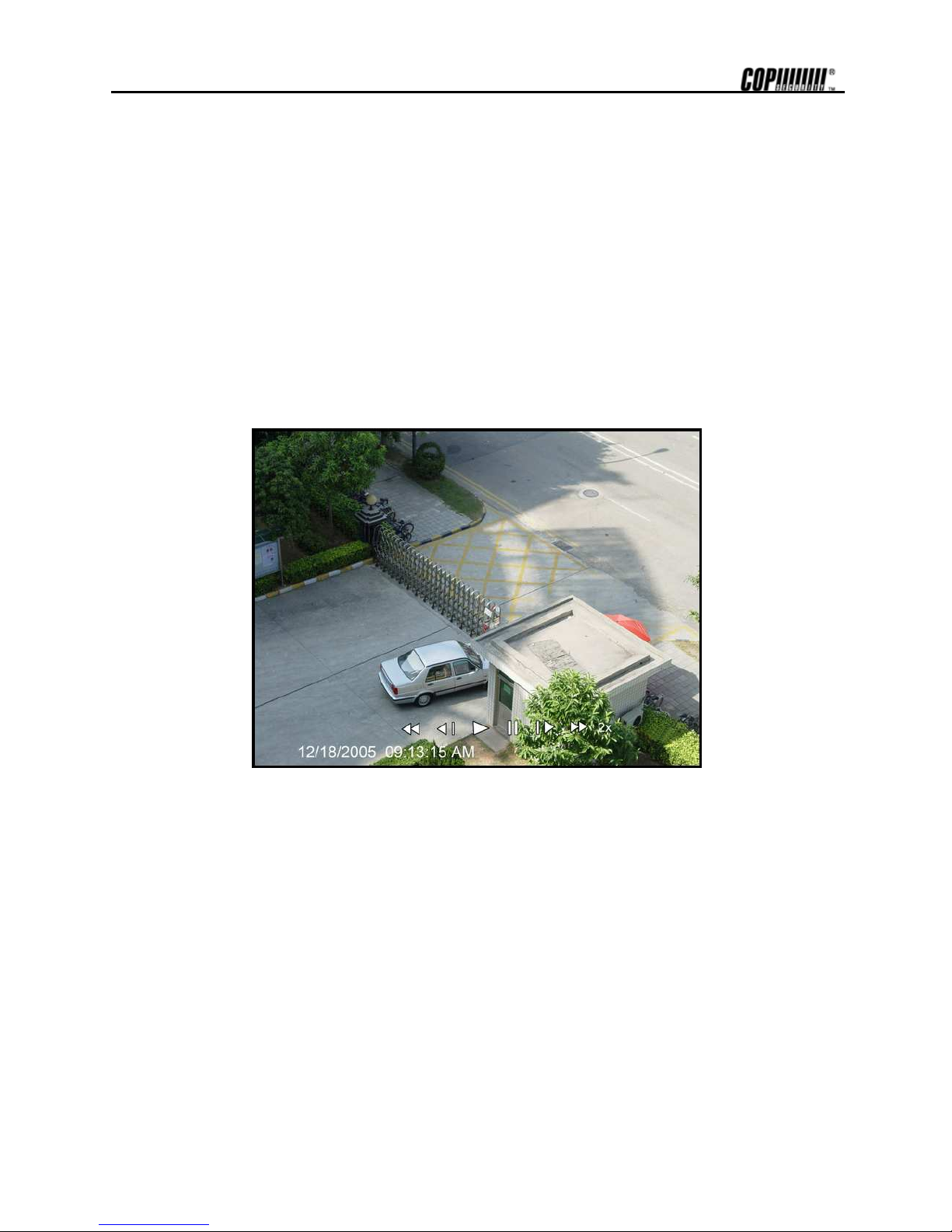
4.3.1. Playback Recording Images
To playback recorded image, press Playback () button from the Front Panel or IR Remote Controller. Press the
Playback button and the latest recording image will be playback.
It is easy to use the Front Panel’s Jog/Shuttle to playback recording files. Turn the Jog and the recorded files can be seen
backwards or forwards frame by frame. Turn the Shuttle and the playback speed can be controlled 2, 4, 8, and 16, 32
times while playback backwards or forwards.
The below picture is when the playback is done 2 times.
Page 24
17
4.4 Search Recording Image
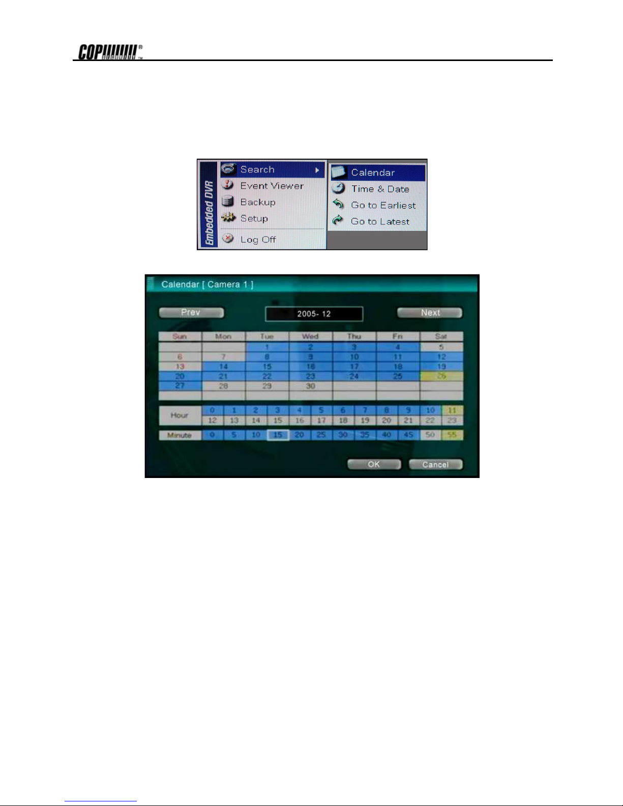
4.4.1. Calendar Search
The user can select date and time to search for a certain file within the recorded image. Press the [Search] button of the
IR Remote Controller and the Search Menu will be indicated on the screen as below picture.
The following below is the sequence to search date and time.
1. Select the date with recorded image by clicking the calendar with the arrow button. The date with recorded
image will be indicated in gray.
2. Move the arrow button to the date desired before pressing [Enter] button of the Front Panel or IR Remote
Controller.
3. Next, move the cursor to the time graph below the calendar to the desired hour range.
4. Then from the min unit graph, select the minute.
5. Move the cursor and press [OK] button and the recorded image for the corresponding time will be recall by
pause state. Press the [Play] button to see the playback of the recorded image.
Page 25
18
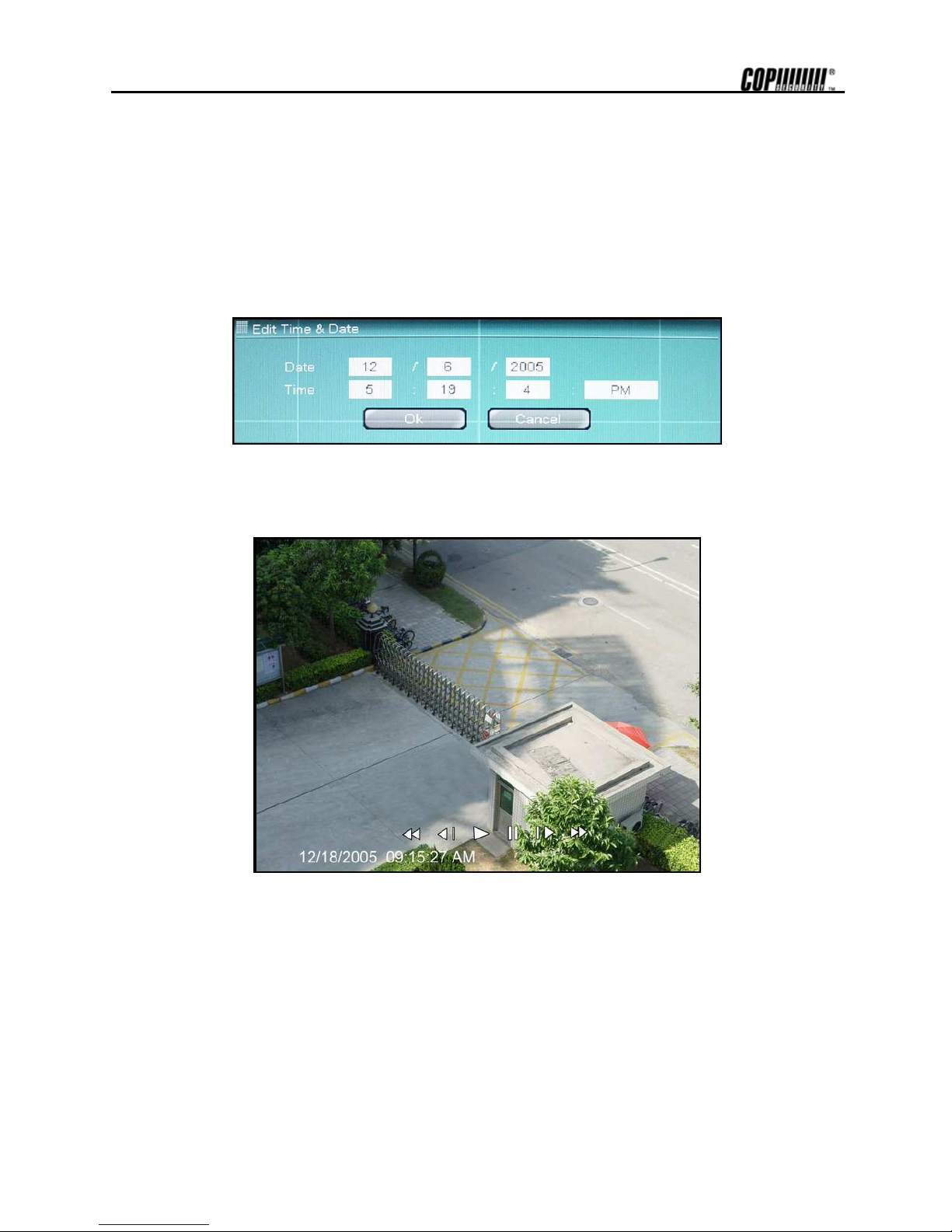
4.4.2. Search Date/ Time
Enter the desired date and time for the user to playback the recorded image.
Select [Search->Date/Time Search] category and the screen as below will appear.
Use the arrow button to move to each day/month/year and time (hour:min:secs AM/PM) category for entering date and
time.
Enter the date and time before pressing [OK] button and the picture as below will appear to show image of the searched
date/time. Image will not appear incase, there is no recorded images. Press [] button to playback the recorded images.
Page 26

19
4.4.3. Event Search
The Event Search function is used to find particular event, quickly and easily.
To see particular event of activated time, move the arrow button of the Front Panel or Remote Controller to the desired
time range.
Following is the category indicated on the Event Viewer.
1. Alarm by Sensor
2. Alarm by Motion
3. Alarm by Video Loss
Select the time and press [Enter] or [] button of the Front Panel or IR Remote Controller, to playback the image of the
time with activating event.
Note
Incase the Alarm does not activate even though the alarm input setting had been done, check the alarm
connection port of the product’s rear panel.
4.4.4. Go to the First
Go to the first screen of the recorded image. This is the oldest image recorded.
4.4.5. Go to the Last
Go to the last screen of the recorded image. This is the latest image recorded.
Page 27

20
5. Setting
To operate DVRSHD series system, appropriate setting values in the setting menu are necessary. Users can either input
or change the settings values listed in the table below.
Main
Classification
Sub Classification Setting Category Default
Resolution 352x240
Sequence Dwell 3
Spot Dwell 3
IR Remote Controller 00
General
Language English
Date and Time
Date Format MM/DD/YYYY
Time Format AM/PM
Date & Time
Daylight Saving US
Admin
Password
User1~5 / Default
Import/Export Setup
Shutdown
System
Close Manu
IPS 30
Quality Standard
Sensitive 80
Area Select All, (Tracking: Off)
Audio 30
Recording
Record ON
Schedule Select Camera
Title & Security
Bright 0
Contrast 0
Color 0
Tint 0
Sharp 0
Color
AGC On
Protocol None
PTZ
Address 0
Audio On/Off Off
Camera
Audio
Two Way Audio Off
On/Off Off
Camera None
Out None
IPS 30
Mode Set
Dwell 5 sec
Pre-Alarm 0 sec
Alarm Alarm In/Out
Type N/O
Page 28

21
Main
Classification
Sub Classification Setting Category Default
On/Off Off
Out None
IPS 30
Dwell 5 sec
Motion Alarm
Pre-Alarm 0 sec
On/Off Off
Alarm Out None
Dwell 5 sec
Video Loss
Pre-Alarm 0 sec
Smart Alarm On
Alarm Out 1
Alarm
Smart Alarm
Dwell Time
Type LAN
IP Address 192.168.000.XXX
Subnet 255.255.255.000
Gateway 192.168.000.001
Mac Address
IP Setting
Band Width Limit
Dynamic IP Server 211.202.003.176
TCP Port 43300
Dynamic IP Server
UDP Port 11000
Notification Server
Email Notify
Email List
Host Name
SMTP Server
SMTP ID
Network
Event Notification
SMTP Password
Signal System NTSC
Software Version
Firmware Version
Disk Usage
IP Address
System Information
MAC Address
Log Number
Log Type
System Log
Date/Time
Backup
Upgrade From CD-RW or USB
Device
Host Address
Current Version
System Upgrade
New Version
Format
Tools
Factory Default
Page 29

22
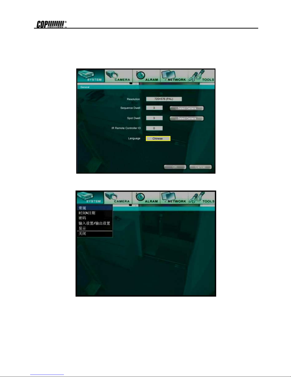
5.1 System - General
Set general user environment of the system.
Use the button of the Front Panel or Remote Controller to select the category and press [Enter] button. Then, detail menu
of each category will appear.
5.1.1. Resolution
Select resolution for the recording image. Here, the resolution means required horizontal and vertical pixel number of a
page. The resolution is indicated as (horizontal) X (vertical) pixel number. Thus, select one setting from 352×240, 720×
240, and 720×480. Default is 352×240. As the resolution number increases, the picture quality is higher. In fact, 352×240
is VHS level and when high quality camera is used, 720×480 show DVD level picture quality. When the picture quality
gets higher, the storage capacity is bigger and the recording period will be shorter. Thus, selecting appropriate resolution
according to the important of the situation.
Page 30

23
Note
The storage capacity for the same image will differ. That is, image per byte is ratio to the image dimensions
(horizontal x vertical) thus 720×240 is twice the size of 352×240 and 720×480 takes about 4 times the storage
capacity.
Therefore when high resolution is selected for the same period, the storage capacity taken up will be larger and
the storage period will be shorter on the same Hard disk capacity.
Note
For the same resolution, frame per byte size will vary according to various reasons such as recording picture
quality setting, movement, complexity of the image and noise. Therefore, total recording period will differ hugely
according to the image particularity.
352×240 : Standard Quality Standard 3~5KB
720×240 : Standard Quality Standard 5~10KB
720×480 : Standard Quality Standard 10~20KB
5.1.2. Sequence Dwell
When Real-time image mode is in automatic sequencing mode, set the time interval between each screen sequence.
Sequence Dwell function is for the user to select certain time interval between each page.
Example, when sequence function is activated on the 1-screen mode, the next screen will be shown in sequence
according to the set time interval. By pressing [SEQ] button of the Front Panel or Remote Controller, activating can be
done. Possible setting limit is 1~60secs and default is 3 seconds.
Press the [Select Camera] button and the following screen below will appear. The user can select automatic channel sequence. Press
[All] to select all the channels. To see the channel sequence, select the camera number and only the camera selected will be
automatically sequencing.
Page 31

24
5.1.3. Spot-out Dwell
Set the screen sequencing of the connected monitor, which had been connected to the product by external output.
Setting can be done by 1~60secs unit. External output cannot use other functions except seeing the image on the screen.
Press [Select Camera] button and the screen as below will appear. Select the camera for the use to see the external output. Tick [All]
and all the channels will be selected. Choose the camera number to see by external output and only the selected camera image can be
outputted.
5.1.4. IR Remote Controller
An IR Remote Controller ID can control several units at once using one remote controller. Thus, ID will be required to be
set to control each unit with one Remote Controller.
Below is the method to set the ID of the IR Remote Controller. Default ID is 00.
1. Insert battery to IR Remote Controller. (AAA Size×2)
2. Press [F1] and [F2] Button of IR Remote Controller together at once for more than 2 seconds.
3. Check if the LED had been lightens up on the IR Remote Controller.
4. Press the ID Number between 00~99 by using the number button of the IR Remote Controller (ex: 03, 55).
5. By using the direction key on the Front Panel, designate the ID number as same as what has been set on the
IR Remote Controller
6. Save the ID setting by pressing the [OK] button on the screen.
Note
All the systems have same ID as default when it is out from the factory. Therefore, if same default value is
used, one IR Remote Controller will control several systems at once. To prevent this, it is advisable to set own
ID for each system. It is easy to change the ID of the IR Remote Controller. The user can change the Remote
Controller ID to control several systems separately.
Page 32
25
5.1.5. Language
DVRSHD series supports several languages. According to the environment, the user can select among English, Chinese, Korean or
Japanese. Select the language and the entire menu will change to the selected language. The following below is the screens when
Chinese had been selected.
[Choose Chinese Menu Screen]
[Chinese Menu Screen]
Page 33
26
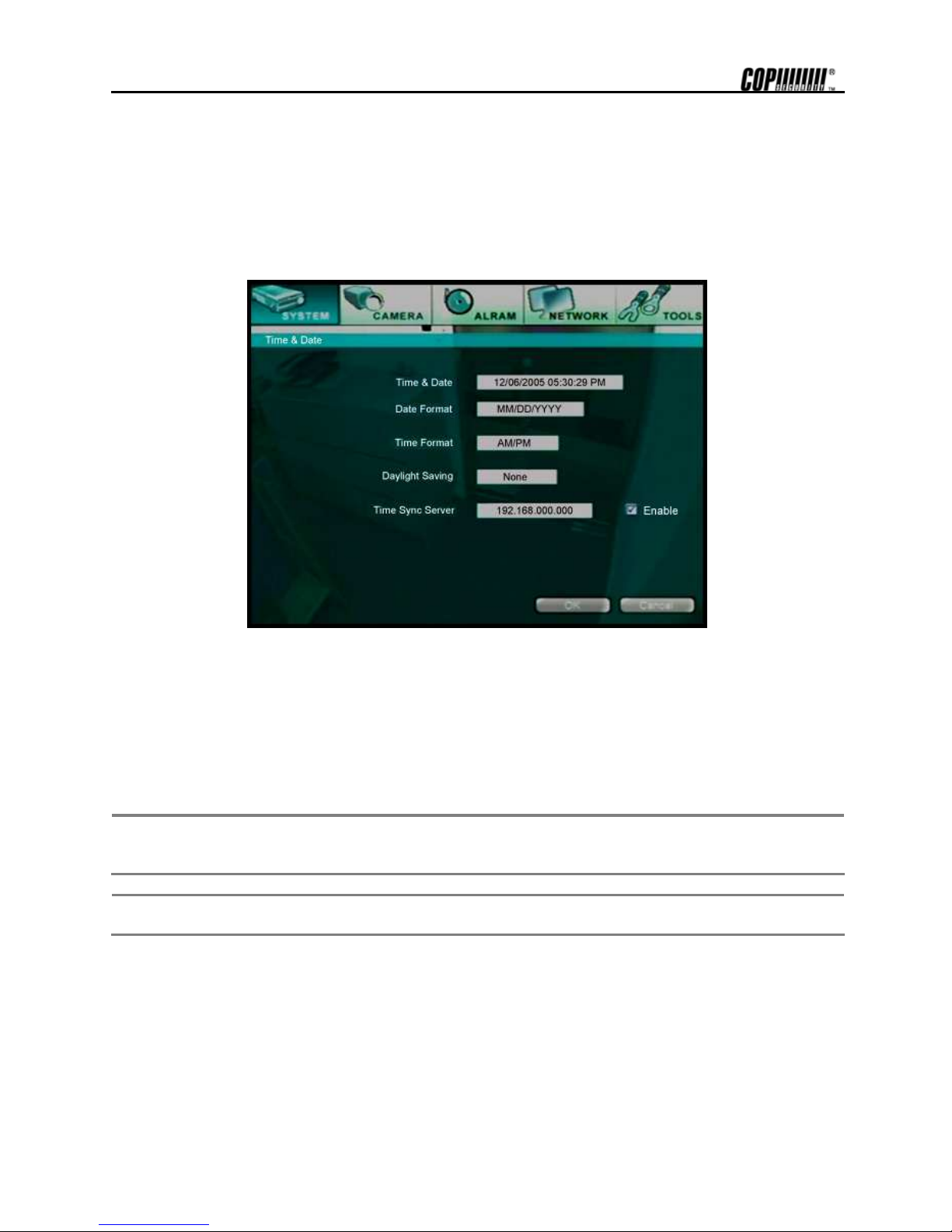
5.2 System - Time & Date
Set the date and time of the system. Below is the setting method to set the date and time.
1. Use the up and down button of the Front Panel or IR Remote Controller to move to the desired category.
2. Press the [Enter] button of the Front Panel or IR Remote Controller to start editing.
3. Allocate the cursor by using the left and right button of the Front Panel or IR Remote Controller for editing and
use the up and down button to change the value.
4. Press the [Enter] button of the Front Panel or IR Remote Controller and the editing will be finished.
5.2.1. Date and Time
Insert exact date and time. Press [Enter] button and the state will change to input date. Input the time and date of the
system accurately as possible as it plays an important role in solving any problem with recorded image or event log.
The current time and date is stored in each recorded images with precision, and they are displayed during playback.
Be cautious that although the time and date stored in recorded images are wrong, they cannot be altered afterwards due
to encryption.
Note
Users can change the time and date to the future without any problem. However difficulty arises when changing
it to the past (the same files might exist in the hard disk). Therefore, under complex recording setting,
unexpected problems might arise in the system.
Note
When a long time has elapsed after setting date/time, it can be distorted. To maintain exact time, date/time
setting should be set once a month.
5.2.2. Date Format
Set the date display format. Use the arrow button to select the desired format in the date display format.
5.2.3. Time Format
Set the time display format. Time format can be selected either by 24-hour or 12-hour base (AM or PM).
Page 34
27
5.2.4. Daylight Saving
Select the daylight saving time for each country. Daylight saving time setting is automatically processed when country is
selected. Supported countries are displayed in the table below.
No. Country Representative Region No. Country Representative Region
1 None GMT 14 Italy Europe/Rome
2 Australia Australia/Melbourne 15 Mexico Mexico/General
3 Austria Europe/Vienna 16 Holland Europe/Amsterdam
4 Belgium Europe/Brussels 17 Norway Europe/Oslo
5 Brazil Brazil/East 18 Poland Europe/Warsaw
6 Canada Canada/Eastern 19 Portugal Portugal
7 Denmark Europe/Copenhagen 20 Russia Moscow
8 Egypt Egypt 21 Slovakia Slovakia
9 Finland Europe/Helsinki 22 Spain Europe/Madrid
10 France Europe/Paris 23 Sweden Europe/Stockholm
11 Germany Europe/Berlin 24 Switzerland Europe/Zurich
12 Greece Europe/Athens 25 UK Europe/London
13 Israel Israel 26 US US/Eastern
5.2.5. Time Sync Server
It is function to synchronize the time of the DVR to the time of the connected sever without adjusting the time of each DVR while
using several DVR.
To use this function, tick on [USE] category and enter the IP address of the connected server.
The time is synchronizing every hour periodically.
Page 35
28
5.3 System - Passwords
Set system passwords for <Admin> and <User>. <Admin> can do the setting for the password only. Each user has to
input designated password to log-on the system. Set the password after selecting [Admin] and [User] by pressing arrow
button.
5.3.1. User
Select user to set the password. The administrator can select the <User> password and the entire category. Maximum
<User> is five (5) and the settings can be done differently for all.
5.3.2. Password
Select the password to change. Max. no. of characters is four (4). The following screen as below will appear when [Enter]
button on [Change] button is pressed. Enter desired password and press [OK] button to save.
Note
To go inside the editing state, use the [Enter] button of the Front Panel or IR Remote Controller and insert the
number by using the number button of the remote controller. After finish editing to enter password, use the
[Enter] button of the Front Panel or IR Remote Controller again.
Page 36
29
Input current password.
Input a new password.
After inputting password, input the same password again.
When the inputted password is completed, message will appear informing that the password had been entered successfully.
5.3.3. Authorization
This is the category to set authorization of <User>. Administer can use the entire category but the settings can be set
differently depending on the <User>. Press [Permission] button and the following screen will be displayed.
Select categories used by each user and press the [Enter] button to check the categories.
The authorization of each category is as following.
1) Power Off : The power of the system can be on and off.
2) Playback : Recording image can be playback.
3) Setup : Each category can be set at the system setup.
4) Camera : Only selected camera image can be seen, depending on <User>.
Page 37
30
5.3.4. Default
The camera image that appears on the screen after login can be selected. Press the [Authorization] button and the following screen as
below will appear. The user can tick the desired camera number. These can be applied on the next login and the selected camera image
can be seen after the login. Press [All] button and all the cameras will be selected.
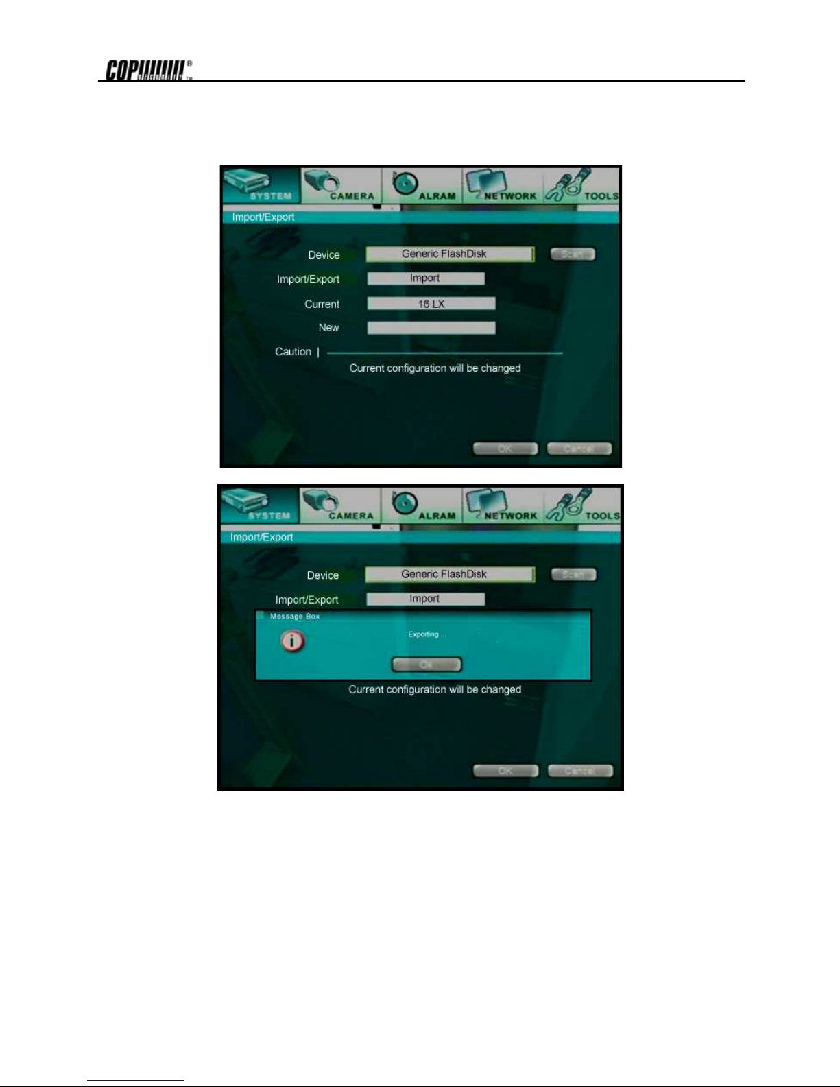
5.4 System – Import/Export Setup
Import setting value from the recorded setting file. Display device list of connected USB and CD-RW when [Scan] button
is pressed. The size of setting file is very small at Import/Export Setup, that only USB disk is supported. Therefore, this
function is not available at the CD-RW. When [OK] button is pressed after selecting USB disk, display version information
and set system.
Page 38
31
Export setting value at the system to the USB disk. Use Import to set value to other DVR.
Page 39

32
5.5 System - Log Off
Log-off <User>, who has been Log-on presently. Log-on by entering <User> or <Admin> authorized password, to activate
system or to go inside the setting menu again. Must Log-off after changing the setting value so that no unauthorized
activation can be done.
Log-off prevents administer and user from using.
Press the [Power] button on the Front Panel or IR Remote Controller to shut down the system.
Page 40

33
5.6 Camera - Recording
Set the desired environment related to camera usage. The screen below shows the setting related to recording.
5.6.1. IPS
Set frame per second for the recording image connected to each camera, which cannot be exceed NTSC: 30fps, PAL: 25fps.
Remaining frame number is indicated at the left bottom of the screen whenever the frame number of each camera is modified.
5.6.2. Quality
Set the recording quality for the corresponding channel according to resolution set. The picture quality can be selected from 4 stages
and they are Highest, High, Standard and Lowest.
The setting value directly influences the byte size per image. For example, the byte size decreases as quality goes lower. In this case,
blocking (mosaic) phenomena tends to appear, which is the artifact caused by high compression. In contrast, blocking phenomena
disappears as quality goes higher. In this case, the required storage space per image increases, which leads to shortening of total
recording period. Therefore, give consideration to the necessary recording period, importance of each camera image, and quality of
analog signal when setting the recording quality. If extending the recording period in high quality, refer to the next explanation
Sensitivity. The byte size decreases when the sensitivity setting decreases.
5.6.3. Sensitivity
Set the motion sensitivity value based on motion detection between 10~100. As the value gets higher, the movement will be saved
without skipping, and as the value gets lower value skips small movements to extend the recording period.
The default is 80, and it is recommended not to change, with the exception of special cases.
Page 41

34
5.6.4. Area
Set motion detection area. Default value is selected as entire area and when the motion detection area is selected, the
movement will be detected according to the area selected. Motion detection will not be done if the area is not set.
.
Set the area by using the direction key of the Front Panel or the IR Remote Controller. The method to set the area is as
below.
1) Use the cursor to move to the area for setting on the screen.
Page 42

35
2) Press [Enter] button and the color of the cursor will change. Then, use the direction key to increase the setting area.
3) Once the setting area is completed, press [Enter] button for confirmation.
4) Press [OK] button to save the content of the settings.
5) Once the area is set, the box will be checked.
6) To set the row and line press the green box of the screen corner.
7) To set the entire area, press the left bottom corner of the screen.
5.6.5. Tracking
It is function to trace and indicate the movement detected on the area set. Yellow box will be indicated on the screen
whenever there is movement on the live display screen. Recording will not be influenced even though [Tracking] function
is not used.
5.6.6. Audio
Select the audio channel to use among the 4 audio input channels.
Note Use amp-equipped device while connecting to the audio input/output device. Although audio is mapped from this menu,
audio recording cannot be done if the audio is not on from Camera-> Audio.
5.6.7. Record
Controls whether to record the channel connected or not. If recording is not required on the selected channels, even when the camera
signal is inputted, set the recording of the corresponding channel as [OFF]. Then, recording of the channel stops without pulling
camera BNC cable off. [ON] or [OFF] can be selected. The default is [ON].
Page 43

36
5.7 Camera - Schedule
Set recording schedule for each camera. First, select the camera to set schedule.
The following picture shows the status of schedule setup for all cameras. Number indicates time.
Recording schedule can be set per hour. Initial indicates the status of recording. The status of recording will be displayed
on the upper right of each channel when the live channel is seen.
The content for each initial is as following.
1) c: Continuous : Continuous recording
2) m: Motion detection : Motion detection recording
3) a: Alarm-activated : Alarm-activated recording
4) ca : Continuous + Alarm-activated recording
5) ma : Motion detection + Alarm-activated recording
6) cm : Continuous recording + Motion detection (Alarm)
Note
Incase the recording is done with ca or ma, the recording will be recorded in continuous or in motion detection.
When alarm activates, concentrated recording will be done according to the set IPS on alarm.
Page 44

37
After pressing [Holiday Setup] button, the below screen is displayed.
Use this function when assigning other holiday other than Saturday and Sunday. The method to assign holiday is as
following.
1. Move cursor to 01/01 (month/day) on the center of bottom.
2. Put cursor in the number section and input month/date by pressing [Up] and [Down] button on the Front Panel
or IR Remote Controller.
3. After inputting desired holiday date, press [Add] button on the right side.
4. Check whether assigned date has been inputted on the screen.
5. To move screen, use [Up] and [Down] button.
6. Close the screen by pressing [Close] button and enter schedule setup screen.
It will be included under Sat in Hol category when it is holiday. Set recording schedule from the category.
Page 45

38
5.8 Camera - Title & Security
5.8.1. Title
Input the camera title of selected camera. Inputted camera title is displayed as OSD (On-Screen Display) and is also displayed on the
recorded files. Therefore when the file is playback on the system or remote site, the camera title will be indicated on the image file
during playback.
Default camera title is “CHn” where n is the channel number. Maximum of 15 characters can be inserted, including capital/small
letters, numbers or spaces.
To move to next group of channels, press [1-8] or [9-16] button that is on the bottom.
Page 46

39
The following screen shows virtual keyboard to input letters.
5.8.2. Security Mode
Set security mode of image screen. When this mode is set up, image cannot be shown on the monitor. Incase the
recording is set; recording will be in progress but will be not shown on the monitor.
5.8.3. Show Title
Select whether to indicate <Security Mode> or <Channel Name> on the monitor screen.
Below picture will explain the setting screens.
1) : [Security Mode : Off], [Show Title : Security]
2) : [Security Mode : On], [Show Title : Security]
3) : [Security Mode : On], [Show Title : Show]
4) : [Security Mode : On], [Show Title : Show]
Page 47

40
5.8.4. Auto Deleting
Set recording periods for each channel. Recording period can be set minimum 1 day to maximum 30 days. Incase the
recording period is set as 30 days, the data after 30 days will be deleted automatically. When 1 day is selected, it will be
applied from the next day. To save the data for longer period, backup the data before automatic backup.
Note
The recorded data will not be deleted until the disk space is full when it is set as None.
Page 48

41
5.9 Camera - Color
Set the brightness, contrast, color and tint of the connected camera. Each setting value can be set – or + value from present value.
5.9.1. Bright
Adjust the brightness (shades) of the channel. If the entire image is dark or bright to a great extent, adjust to the adequate value.
5.9.2. Contrast
Adjust the contrast, which is the ratio of brightness to darkness of the image. Greater the value, brighter the
bright side becomes, and the dark side darker becomes. In case the value is increased to the extent where too much saturation is not
observed in the image, higher contrast can be helpful to display the image vividly.
5.9.3. Color
Adjust the color density. In most cases except for the deterioration of cameras or very low quality cameras, the adjustment of this
value is not required.
Page 49

42
5.9.4. Tint
Set the color hue of connected cameras. In most cases except for the deterioration of cameras or very low quality camera, the
adjustment of this value is not required.
5.9.5. Sharp
Clearness will be higher when the boundary of the image is more distinguished. It is efficient to use when it is hard
to distinguish the object but when the setting value is too high, disadvantage is that picture quality will become
lower.
5.9.6. AGC
It is a function to make the image brighter by increasing the signal automatically on dark places. When the setting value is too high,
image will be brighter but the disadvantage is that the picture quality will be lower.
Page 50
43
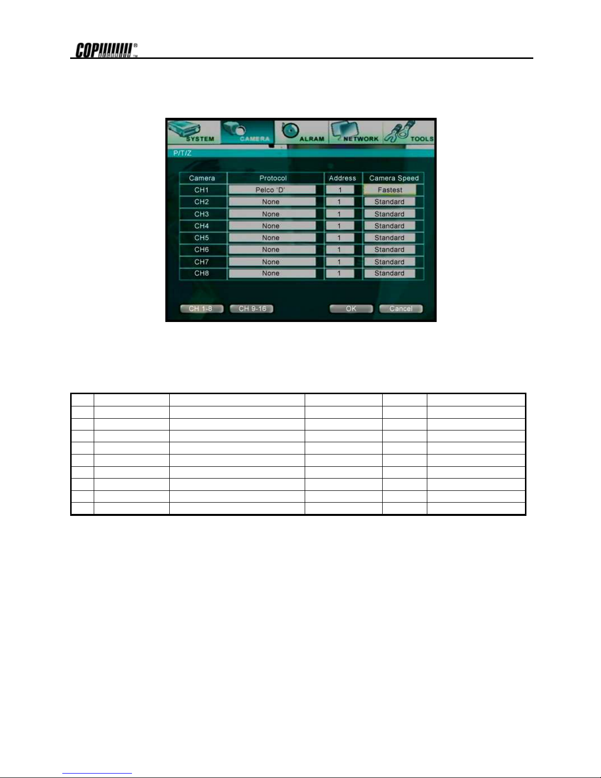
5.10 Camera - PTZ
Set the camera audio and P/T/Z environment.
5.10.1. Protocol
Set the protocol to control the P/T/Z controller connected to P/T/Z port on the back panel. P/T/Z controller is also called receiver or
RX if it becomes separated from camera. Default is NONE, which indicates that the P/T/Z controller protocol is not set. Protocol
currently supported is shown below.
1 Ernitec 2400 baud rate no parity 8bit 1 stop bit
2 Kalatel 9600 baud rate no parity 8bit 1 stop bit
3 Panasonic 19200 baud rate no parity 8bit 1 stop bit
4 Pelco D 2400 baud rate no parity 8bit 1 stop bit
5 Pelco P 4800 baud rate no parity 8bit 1 stop bit
6 Scc-641 9600 baud rate no parity 8bit 1 stop bit
7 Sensormatic 2400 baud rate no parity 8bit 1 stop bit
8 Smart Scan 9600 baud rate even parity 8bit 1 stop bit
9 VC_C4 9600 baud rate no parity 8bit 1 stop bit
10 Vicon 4800 baud rate no parity 8bit 1 stop bit
Set the controller address correctly for each channel after setting the protocol.
5.10.2. Address
Set the P/T/Z driver address of the connected camera.
Check the below items for proper P/T/Z operation.
1. Check if the protocol of all P/T/Z controllers connected to the system is in accordance.
2. Check if the communication setting including baud rate of all P/T/Z controllers is in accordance with the assigned value for that P/T/Z
protocol.
3. Check if the address of all controllers is in accordance with the controller address assigned in the setting menu for that channel.
4. Check if the power of the P/T/Z controller is turned on.
5. Check if wiring to P/T/Z controllers is correct.
Page 51
44
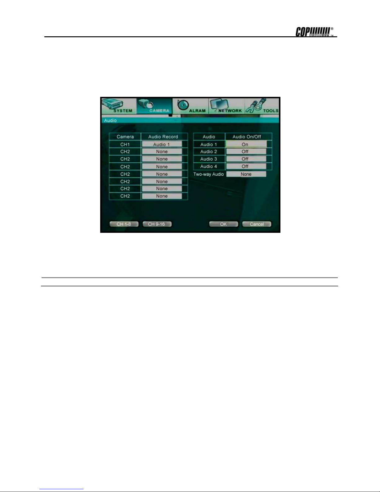
5.11 Camera - Audio
Select whether to use audio recording. Select On/Off in the audio tap for each camera.
To use audio function, connect audio system (speaker and microphone) when setting system.
5.11.1. Two - Way Audio
Two - Way Audio is function to hear voice and talk from both sides of the system and RemoteAgent. Two - Way Audio
function can be used on only one channel from all channels. When the Two Way Audio function is used, the audio will not
be recorded even though a channel’s Audio category has been set to record.
Note
Speaker and microphone should be set up in the connecting system and PC with connected RemoteAgent.
Page 52

45
5.12 Alarm - Alarm In/Out
This is the setting menu screen for alarm-activated recording and camera, connected with DVRSHD series system.
5.12.1. On/Off
Select whether to activate alarm. Press [Enter] button and select On/Off.
5.12.2. Camera
Select camera channel number to connect with the alarm.
When sensor activates, the image of the corresponding camera image will be recorded according to the frame set. Recording time of
the sensor changes according to sensor type and alarm schedule. Change back to previous status if recording is done.
Page 53

46
5.12.3. Out
Select connected number (1,2 or None) to use for activating alarm.
5.12.4. IPS
Set the desired number of frames for the recording of the connected camera. Set no. of frames according to each camera.
When a, ca, ma has been set on the schedule, the recording will be done according to the frames set on the IPS.
5.12.5. Mode
Select either Set or Duration depending on the desired alarm action.
Set:
Once the sensor is detected in this mode, the camera will be recorded according to the frame set during setting time in Dwell tab. That
is, recording will be done during Dwell period from sensor input activation even if the sensor is cut off.
Duration:
In this mode, the alarmed camera will be recorded while sensor is activating.
A channel starts record while other channels in the group stops recording, whenever the sensor is detected. Also when the relay
(output) for the sensor has been set, it will activate together with the sensor.
5.12.6. Dwell
Set the recording period from the start of sensor input activation. During this period, the corresponding camera image will record
according to the frame and alarm (relay) output set. The recording stops and alarm output is turned off when the setting period is
elapsed. Set the alarm-operating period (1~99 seconds).
5.12.7. Pre-Alarm
Set recording time just before perceiving sensor input. Pre-Alarm time is the opposite of Dwell time and it intensively records the
time before alarm activates.
For example, Pre-Alarm is set 20 seconds. If the alarms activates at 14:30:00 on 14th of February, the recording starts from 14:29:40
on 14th of Feb.
5.12.8. Type
Select the sensor type between N/O(Normal Open) and N/C(Normal Close), connecting to alarm input plate. Circuit of N/O type is
usually open, and the activation of the sensor occurs at the time of close, and N/C type works the reverse way.
Note Check the setting of the sensor type (N/O or N/C), if the sensor does not operate properly.
The alarm might not function if the actual connecting sensor type and the sensor type in the system setting are
inconsistent.
Page 54
47
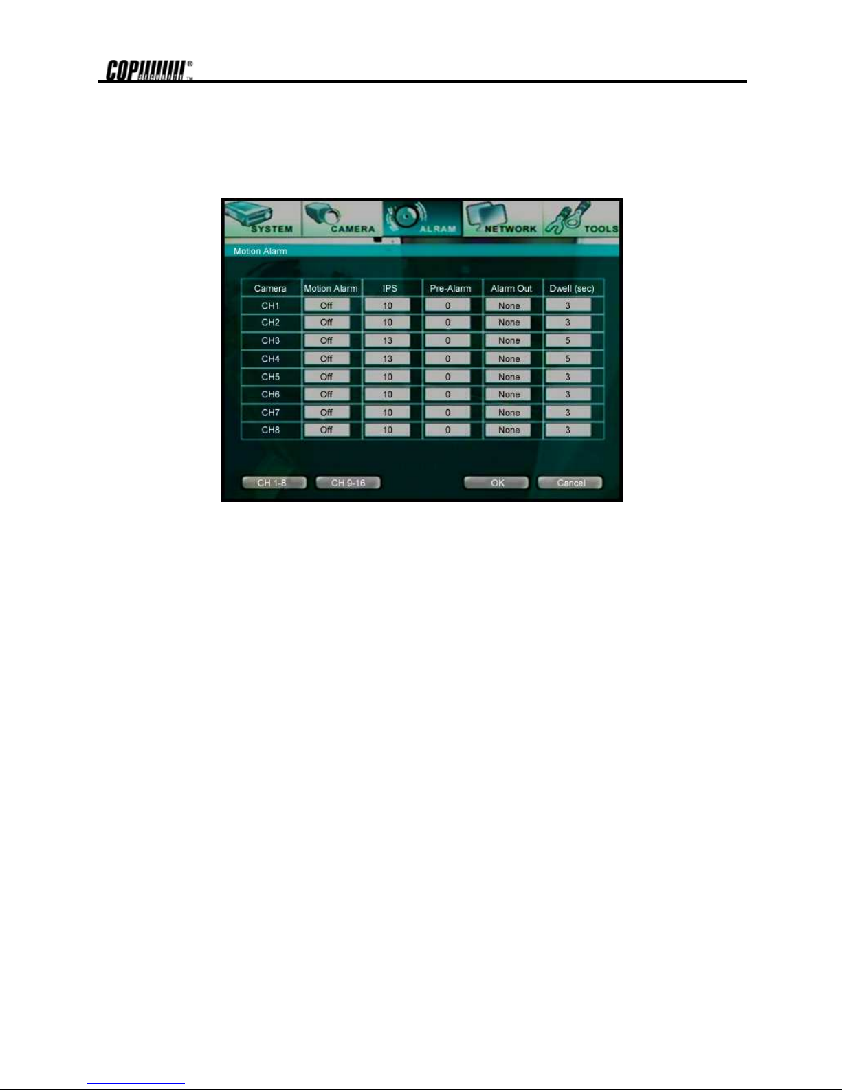
5.13 Alarm - Motion Alarm
Set alarm activating, recording frame and time for motion detected on camera image. Set, while using Motion Alarm. To
use the Motion Alarm, set <m+a> at the Schedule
5.13.1. On/Off
Select whether to use motion detection activated with each channel.
5.13.2. Out
Select connected number (1,2 or none) of output (relay) to use when the alarm activates.
5.13.3. IPS
Set no. of frames for the camera image connected while alarm activating. Each camera can be set in different no. of
frames.
5.13.4. Dwell
Set the period of recording when motion ends after motion activates. This is different from Dwell time in [Alarm In/Out]
category. The Dwell time in [Motion Alarm] category is period of recording from the point when the motion disappears after
motion activation.
5.13.5. Pre-Alarm
Set recording time just before perceiving alarm input. Pre-Alarm time is opposite of Dwell time and it records the time before motion
activates.
For example, Pre-Alarm is set as 20 seconds. If the alarms activates at 14:30:00 on 14th of February, the recording starts from
14:29:40 on 14th of Feb.
Page 55

48
5.14 Alarm - Video Loss
Set to display alarm when the connected camera BNC cable is disconnected or has been pulled off accidentally.
5.14.1. On/Off
Select whether to use Video Loss connected with each channel.
5.14.2. Alarm Out
Select connect number (1,2 or number) to use when activating alarm.
5.14.3. Dwell
Set the period for alarm output while Video Loss is activating.
5.14.4. Pre-Alarm
Set recording time before perceiving Video Loss. Pre-Alarm time is opposite of Dwell time and it records the time before Video Loss
activates.
For example, Pre-Alarm is set as 20 seconds. If the alarm activates at 14:30:00 on 14th of February, the recording starts from 14:29:40
on 14th of Feb.
Page 56
49
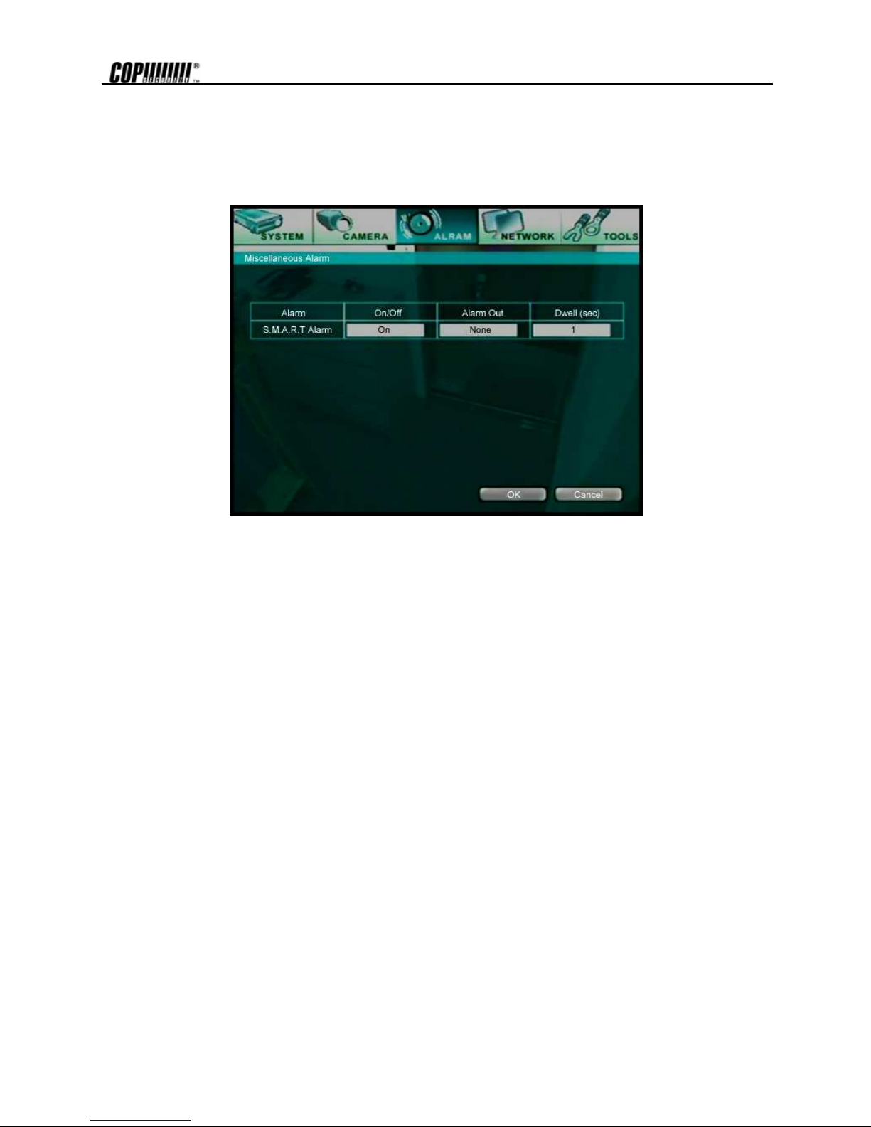
5.15 Alarm – Miscellaneous Alarm
The user can set Smart Alarm indication and alarm dwell time relating to hard disk pre-hand before error or problem occurs on the
hard disk installed.
5.15.1. Smart Alarm
Select whether to use the Smart Alarm function.
5.15.2. Alarm Out
Select connection number (1, 2 or None) of output (relay) used while activating alarm.
5.15.3. Dwell Time
Set the alarm activating time showing on the screen when the error had occurred on the hard disk.
Page 57
50
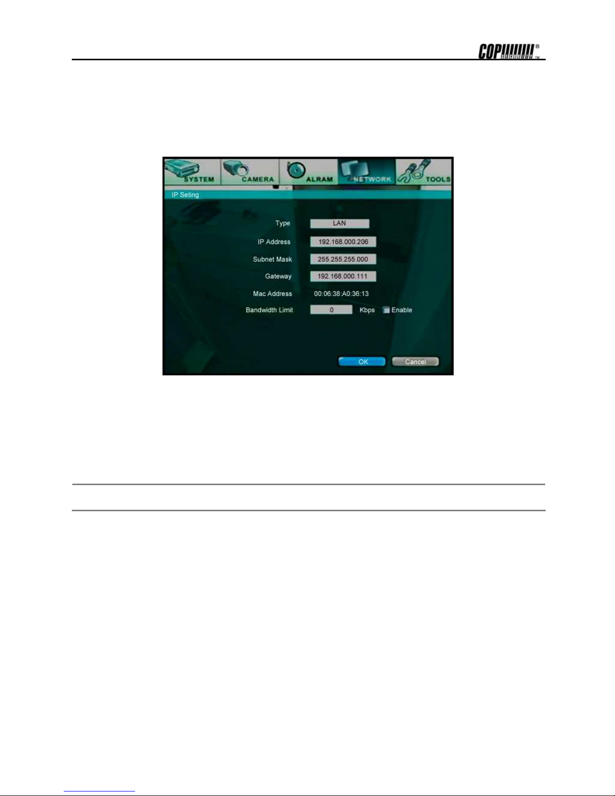
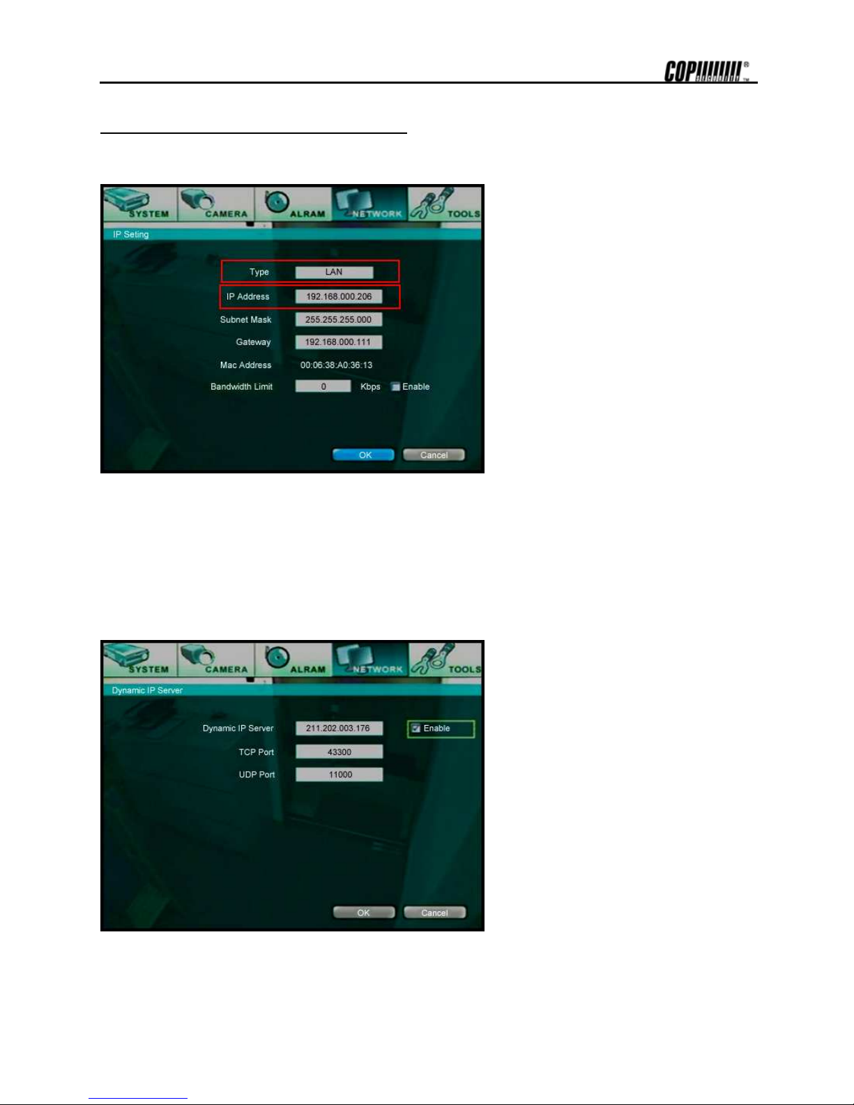
5.16 Network - IP Setting
Set the network environment of the system.
Input the numbers, using direction key or number buttons of remote controller.
5.16.1. Type
Select network connect type. Select either LAN or DHCP.
5.16.2. IP Address
Input the IP address assigned to DVRSHD series system.
Note Use fixed IP for system IP.
For system IP, use the IP that is not used by other PC or DVR.
Page 58

51
5.16.3. Subnet
Subnet Mask address recognizes the subnet to which the system belongs. Default is 255.255.255.0. Consult network administrator for
accurate information.
5.16.4. Gateway
This is the IP address of the network router or gateway. It is required when the user wants to connect through the external router from
the remote. Default is 192.168.0.1.
Note Consult your vendor if network connection configuration is required.
5.16.5. MAC Address
The MAC address assigned to DVRSHD series system is displayed. MAC Address cannot be modified.
5.16.6. Band Width Limit
Set bandwidth when limiting network transmits speed. Check [Use Limit] category and set bandwidth. Below is the screen
when setting bandwidth.
Page 59

52
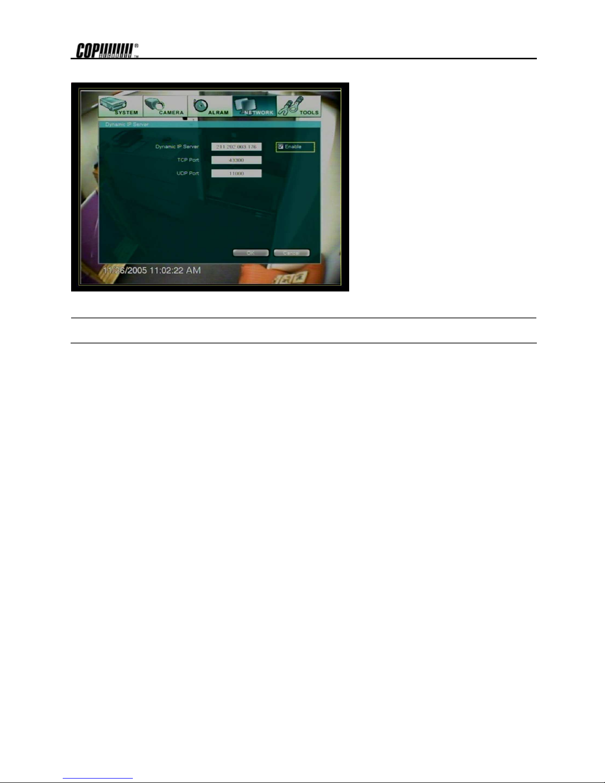
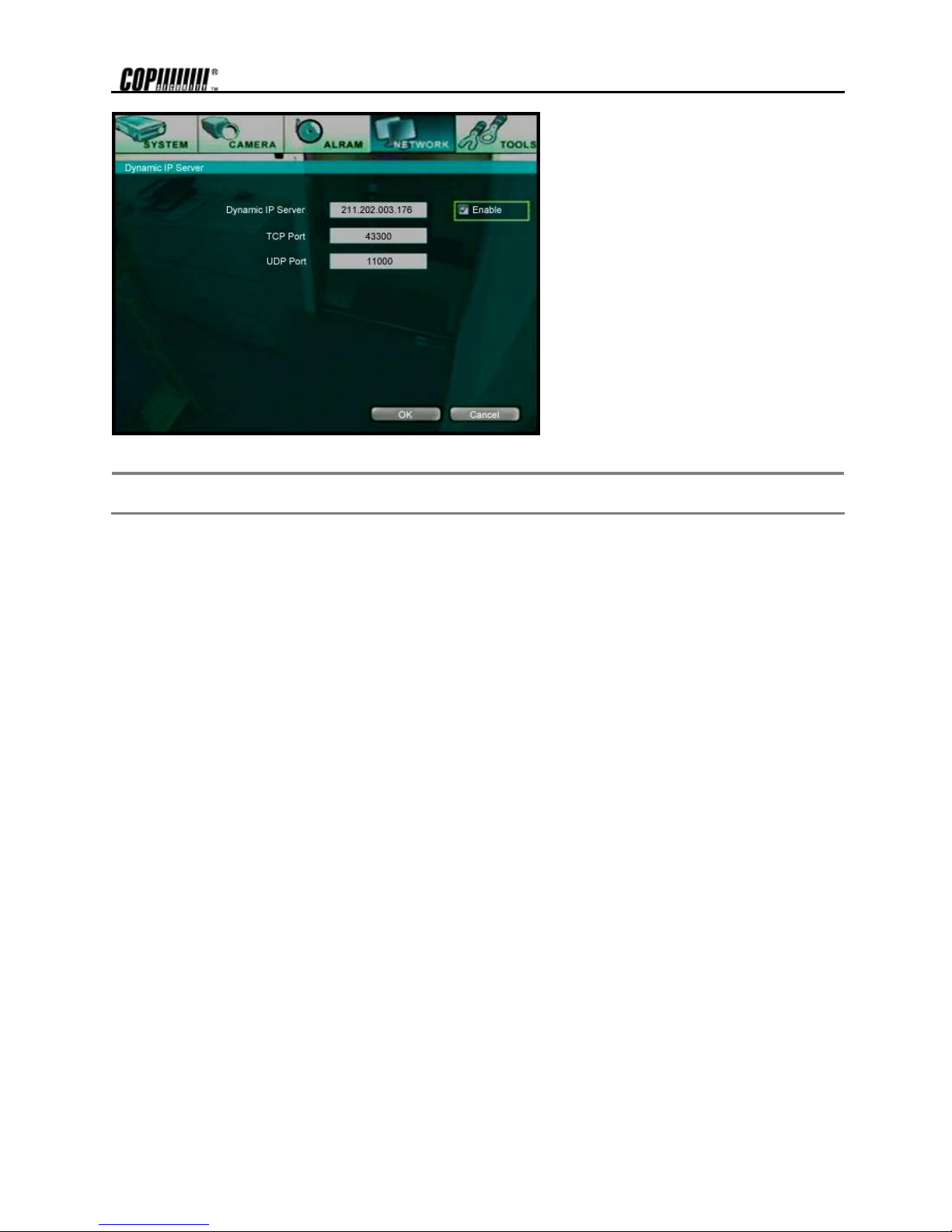
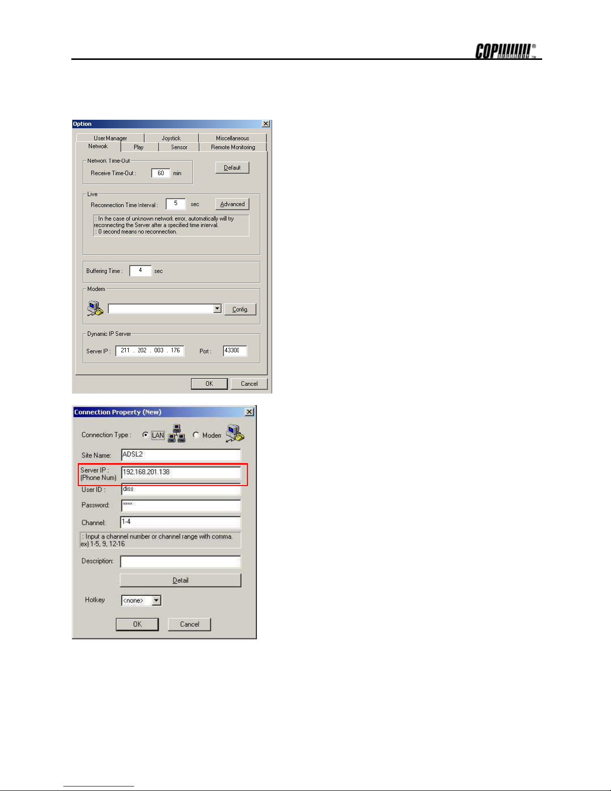
5.17 Network - Dynamic IP Server
Set network environment of system.
The number buttons on the IR Remote Controller can be used as direction keys. First, check [On/Off] category.
5.17.1. Dynamic IP Server
Input IP address of the Dynamic IP Server. (Default: 211.202.003.176)
5.17.2. TCP Port
Input port number to communicate with Dynamic IP Server. (Default: 43300)
5.17.3. UDP Port
Input UDP port number to communicate with Dynamic IP Server. (Default: 11000)
Note
IP address of Dynamic IP Server can be modified. Consult vendor about detail IP address and port number if
abnormal operation happens, despite being set with default.
Page 60

53
Fixed Public IP
1) Set the network [Type] to LAN.
2) Enter the IP Address, provided by the Internet
Company.
3) Tick off [On/Off] category, as the Dynamic IP
Server is not used.
Note
Incase network cannot be connected after completing the settings, try connecting the cable to another PC. This is to check
if the network (internet) connection is working properly.
Page 61

54
Dynamic Public IP
Incase only xDSL modem is used without Router. (Note: Does not support PPPoE modem).
1) Set the network [Type] to DHCP.
2) Tick on [On/Off] category from Dynamic IP Server.
3) Do not change the fixed setting value of the Dynamic IP Server and the ports. If
Page 62

55
the value is changed, the network connection may not be possible.
Dynamic IP Server : 211.202.003.176
TCP Port : 43300
UDP Port : 11000
Note
Incase network cannot be connected after completing the settings, try connecting the cable to another PC. This is to check
if the network (internet) connection is working properly.
Page 63

56
Incase xDSL modem and Router is used
(PPPoE modem can be used if Router that is compatible with the PPPoE function is used).
5.17.4. Incase DMZ function of the Router had been used for connection
1) Set the network [Type] to LAN.
2) Enter the value on IP Address,
Subnet, and Gateway with the value
that had been used to enter while
setting DMZ function of the router.
If you need to open TCP(UDP)/IP port in a
router, then please refer to below list ;
1. Log on: 7000
2. Live Transmission: 8000,8001
3. VOD (Remote Playback)
Transmission: 9000,9001
4. Automatic connection when alarm
activated: 8003
5. Time synchronization: 8900
6. Two-way Audio: 7021
7. Remote configuration (Web Server):
80
8. DYIP Check: 10101, 43300, 11000
(UDP)
Page 64
57
3) Tick on [On/Off] category from
Dynamic IP Server.
Do not change the values of the Dynamic
IP Server and each port that are fixed. The
network connection may not be possible if
the inputted value is modified.
Dynamic IP Server : 211.202.003.176
TCP Port : 43300
UDP Port : 11000
Note
Incase network cannot be connected after completing the settings, try connecting the cable to another PC. This is to check
if the network (internet) connection is working properly.
Page 65

58
Incase Port Forwarding function of the Router had been used for connection
1) Set the network [Type] to LAN.
2) Enter private fixed IP provided by the Router for IP Address, Subnet, and Gateway
value. (Refer to content on 2.2.3 when the Router uses DHCP).
For Port Forwarding, the TCP (UDP) / IP Port as below will have to be opened.
1. Log on: 7000
2. Live transmission: 8000,8001
3. VOD (remote playback) transmission: 9000,9001
4. Automatic connection when alarm activated: 8003
5. Time synchronization: 8900
6. Two-way Audio: 7021
7. Remote configuration (Web Server): 80
8. DYIP Check: 10101, 43300, 11000 (UDP)
3) Tick on [On/Off] category from
Dynamic IP Server.
Do not change the values of the Dynamic
IP Server and each port that are fixed. The
network connection may not be possible if
the inputted value is modified.
Dynamic IP Server: 211.202.003.176
TCP Port: 43300
UDP Port: 11000
Page 66
59
Note
Incase network cannot be connected after completing the settings, try connecting the cable to another PC. This is to check
if the network (internet) connection is working properly.
Page 67
60
Incase DHCP function of the Router is used for connection.
1) Set the network [Type] to LAN.
2) For the IP Address, enter an IP, which must be beyond the DHCP IP range set by
Router.
Ex) DHCP IP range set by Router is between192.168.0.0 ~ 192.168.0.50. Then the IP
that can be entered on the DVR shall be above 192.168.0.51.
3) Tick on [On/Off] category from Dynamic IP Server.
Do not change the values of the Dynamic IP Server and each port that are fixed. The
network connection may not be possible if the inputted value is modified.
Page 68

61
Dynamic IP Server : 211.202.003.176
TCP Port : 43300
UDP Port : 11000
Note
Incase network cannot be connected after completing the settings, try connecting the cable to another PC. This is to check
if the network (internet) connection is working properly.
Page 69
62
RemoteAgent Setting
1) From the RemoteAgent, go to [Option]-> [Network]
folder and enter [Server IP] and [Port].
Server IP: 211.202.003.176
Port: 43300
Incase the IP set on the DVR is Fixed IP, enter the IP of the
corresponding DVR while registering site on the
RemoteAgent.
Ex) 192.168.201.138
Page 70
63
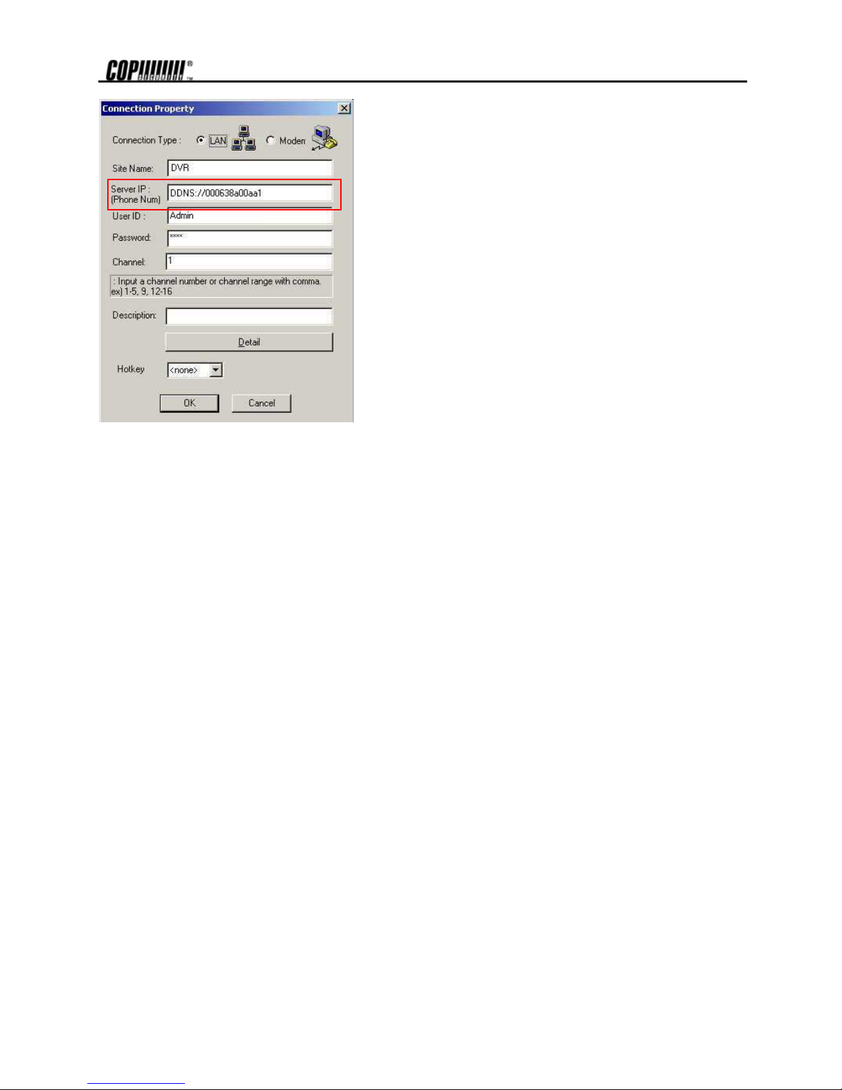
Incase the IP set on the DVR is Dynamic IP, enter the Mac
Address of the corresponding DVR while registering site on
the RemoteAgent.
Ex) DDNS://030638a00aa1
Page 71
64
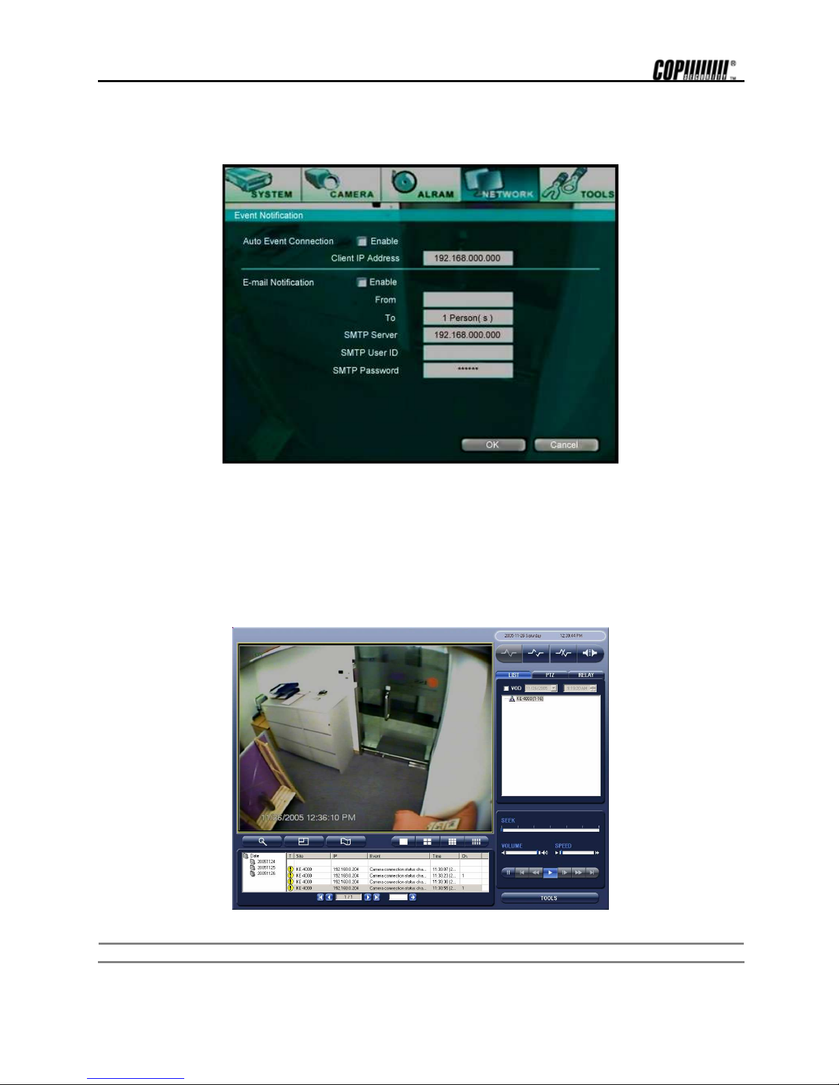
5.18 Network-Event notification
It is a function to send contents of event to the users’ e-mail address when an event activates.
5.18.1. Notification Server
RemoteAgent, installed on the user PC, can get the image transmission of the activated event. Tick on the [Notification Sever] to use
the function.
Enter the IP address of the PC to receive the transmitted image of the activated event. To receive the image of the event, the
RemoteAgent will have to be running on the PC.
When event activates, the image with the event list will be transmitted to the RemoteAgent screen.
Note
Enter all the contents and press the [OK] button to save.
Page 72
65
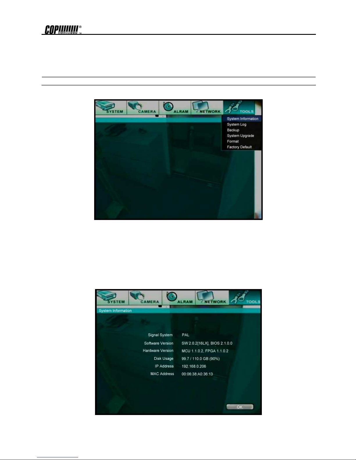
5.19 Tools-System Information
This is the system information screen of DVRSHD series.
Note The details in the information screen can be different, based on the model number and system environment.
5.19.1. Signal System
The type of video signal is displayed: NTSC or PAL.
5.19.2. Software Version
Software version installed in the system is displayed.
5.19.3. Firmware Version
Firmware version of the system is displayed.
Page 73

66
5.19.4. Disk Usage
Hard disk usage is displayed. (Used/Total HDD space (Remaining space%))
5.19.5. IP Address
IP address of the system is displayed.
5.19.6. MAC Address
MAC address of the system is displayed.
Page 74

67
5.20 Tools - System Log
This is use to see information being used in the DVRSHD series system.
To see more information, press the [Enter] button after moving cursor to the [Up/Down] button with direction button.
Display previous or next page.
5.20.1. Log Type
These are the operations that happen in the system. The operations that happen in the system are briefly notified.
Displayed Log Type is displayed.
1. Power On
2. Power Off
3. Record On
4. Record Off
5. Setup Begin
6. Setup End
7. Playback Begin
8. Playback End
9. Disk Full
10. System Time Change
11. Smart Alarm HDD1
12. Log On
13. Log Off
5.20.2. Date/Time
Display Date and time of operations that happen in the system.
Page 75

68
5.21 Tools - Backup
There is two kind of method to backup recorded date in the DVRSHDseries. First method is using the CD-RW Drive
(selected specs) to backup by CD and second method is using the USB external storage device for backup.
Use the CD-RW Drive or USB Device attached to the DVRSHD series to backup the recorded images.
Press the [Backup] button on the IR Remote Controller and the following screen will appear.
Note
The specifications of the CD-RW Drive will be shown differently, according to the model. Refer to the CD-RW
Drive manual for detailed information.
Error message will appear when the CD-RW is not installed or not properly connected.
Note
Consult with your vendor if detailed information of the CD-RW is required.
Note
The following is the list of media supported in the internal CD-RW of the DVRSHD series.
CD-R :
Acer, AMT, CMC, Kodak, LeadData, Maxell, Mitsubishi Chemical, Mitsui, Nan Ya, Philips, Princo, Prodisc,
Ricoh, Ritek, Sony, Taiyo Yuden, TDK, Verbatim, Yamaha
CD-RW :
Acer, AMT, CMC, Digimaster, Maxell, MaxMax, Melody, Mitsubishi Chemical, Philips, Plextor, Prodisc, Ricoh,
Ritek, Sony, TDK, Traxdata, Verbatim, Yamaha
Page 76

69
Enter each item on the screen below to backup recorded images.
1. Select the recording start time for backup.
2. Also, select the recording end time for backup.
3. Select channels to backup. The user can select several channels together, but if the backup data capacity is more than the storage
capacity, backup will not proceed. Select the channel by using the cursor and pressing [Enter] button.
4. After selecting all the items, press [Next] button to proceed to the next screen.
5. Calculate the file for backup.
6. Advise for file size and you have to confirm file copying.
Page 77

70
7. When the backup has been done properly, the message as below will appear.
Incase the operation had been canceled while backup, the error message will be appeared.
Incase the CD-R Media (Blank CD) for backup has not been inserted on the drive, “Unknown system error!” message
will be appeared.
In case the space of the CD-R is too small or the storage capacity is too huge, the “Not enough disk space for backup.”
error message will be appeared. Prepare larger capacity CD-R or decrease the time of the backup image.
Page 78

71
5.22 Tools - System Upgrade
This screen appears during system upgrade. Upgrade can be done through LAN, CD or USB.
5.22.1. Upgrade From
Select media to upgrade when upgrading system. Media is displayed when [Scan] button is pressed.
5.22.2. Device
Display type of selected upgrade media.
The following sequence is how to upgrade using the internal CD-RW.
1. Prepare upgrade image CD.
2. Put the prepared CD inside the CD-RW of the system.
3. Select CD-ROM from Select category of the upgrade menu. Then, select the [Start] button. Copy upgrade file from CD.
4. Upgrade copied file from the system.
5. When the upgrade is completed without any error, no error message will be displayed and the system will automatically reboot
after upgrade.
This screen appears when system could not recognize the upgrade bin file and the error message will be
appeared.
Page 79

72
5.22.3. Host Address
Input the host server address when upgrading through TFTP server
5.22.4. Current Version
Displays the version of the software that is being used in the system.
5.22.5. New Version
Displays the version of the software that you want to set in the system.
5.22.6. Progress
Displays the progress while upgrading.
.
5.23 Tools-Disk Format
Supports the attached HDD format of the system.
Note
HDD format is not supported for the HDD that had been using, as surveillance will be vulnerable.
Select Disk Format category and the following screen will appear.
Select the HDD to format and check the capacity. Press [OK] button and the format will be proceeding.
The HDD cannot be formatted when there is only one. It can be format when the HDD is installed for the first time.
Error message as below will appear while preceding the format. Thus, check the user and installation status.
Page 80
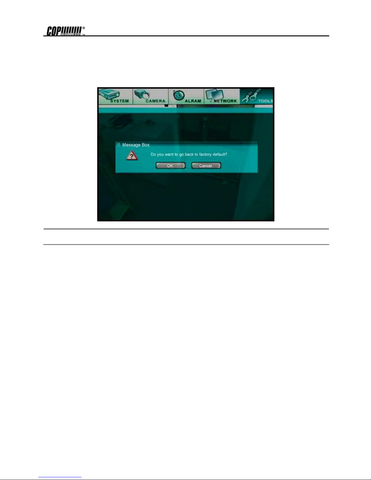
73
5.24 Tools - Factory Default
This screen allows the users to return to the factory default setting. In this case, current setting values will be ignored and all the
settings will return to factory default except the network setting and password.
All setting values, except for the network setting and passwords, return to default value when [Yes] button is pressed.
Note In the Tools Default setting, the entire values will be returned to the default setting, thus desired setting values should be
kept separately for future use.
Page 81

74
6. Remote Setting
6.1 Remote System Setting
Incase the DVRSHD series is connected to the network; the system setting can be changed using the web browser from the remote
site. Login screen will appear when the IP address of the DVRSHDseries is inputted on the web browser’s address.
Below picture is the first screen of remote setup that appears when the system is connected with the web
browser.
According to the user’s window environment, the screen may differ a little.
Note
The <Admin> password of the local system has to be setup, to use the remote setting. The remote setup function does not
activate if the [Setting] menu of the local system is running or when it is upgrading. Note that problem may occur if any
operation on the local system is done while remote setting.
Page 82

75
6.2 Remote Monitoring
By entering the IP address of the system, the system image can be seen from the web browser without running the RemoteAgent.
This function is simply a monitoring function, for viewing image.
Depending on the user’s PC environment, select the image size between from 640x480 / 320x240.
Note
There may be a bit of problem in network transmission, according to the user’s network environment.
 Loading...