

Page 1

-1-
4CH Digital Video Recorder
User’s Manual
Page 2

-2-
Table of Contents
1. System Specification
2. Operation Guide
A. Power UP
i. View Mode
ii. Change Channel
B. Basic Function
i. Record (REC)
Start recording
Stop recording
ii. Playback
Start Playing
Fast Forward
Reverse
Pause/Playback by single frame
Stop Playback
C. DVR Menu
3. DVR installation
A. Connect to your TV set
B. Camera installation
C. Sensor installation
D. Alarm Installation
Appendix
i. Regulatory Information
ii. Reference on HDD capacity’s calculation
iii. Built-in HDD’s installation
Page 3
-3-
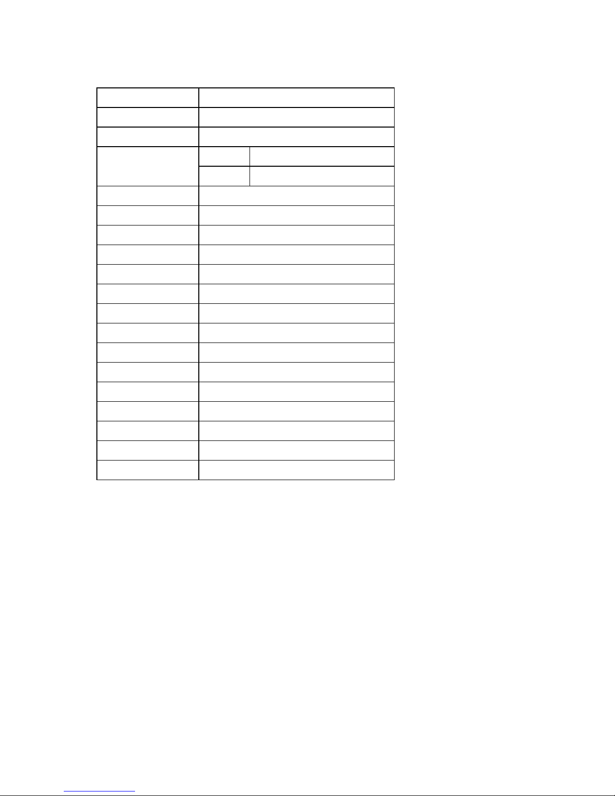
System Specifications
Signal System NTSC/PAL
Display frame rate 100fps(PAL)
Record frame rate 25fps(PAL)
Live 720x576(PAL) Resolution
Play Back 640x272 (PAL)
Compression algorithm MJPEG
HDD 40GB to 200GB
Record mode Manual, Alarm, Timer
Searching for Playback Event List, Timer
Backup VCR (Option)
Alarm In/Out 4 In NO/NC, 1 Out NO/NC relay
Video Input BNC x 4
Video Output BNC x 2
Adapter DC 12V 2A,DC 5V 4A
Operation thermometer 5~40 (41~104)
Operation humidity Less 90%
Operation power 18W
Size 235mm X290mm X 55mm (WDH)
Weight 2.3 kg (no HDD)
Accessories Adapter, Power cord, user manual
Page 4
-4-
Operation Guide
A. Power Up
If the DVR is properly installed (refer to chapter 4 for more detail on DVR installation), The DVR is ready to
record and play digitally processed video stream. Then apply power , the unit will automatically power on.
[NOTE] Please, make sure that the DVR is properly installed
before the power up.
i. View Mode
When the DVR starts up, it enters the default operational state, “View” mode. In this mode, the DVR does not
record, and does not play the recorded video stream. It just shows the current images from each camera
connected to the DVR.
[NOTE] There’s an exception on entering DVR “View” mode.
That is “Power Recovery,” which would be performed when the DVR detects that previously the DVR was shut
down without stopping the recording process.
ii. Change Channel
The default display setting of the DVR is to display all 4 channels at the same time reducing the each channel’s
image size. With this setting, you can see all 4 channels at the same time. However, when you want to see only
one channel on full screen, which means large image, you can simply select a channel and display.
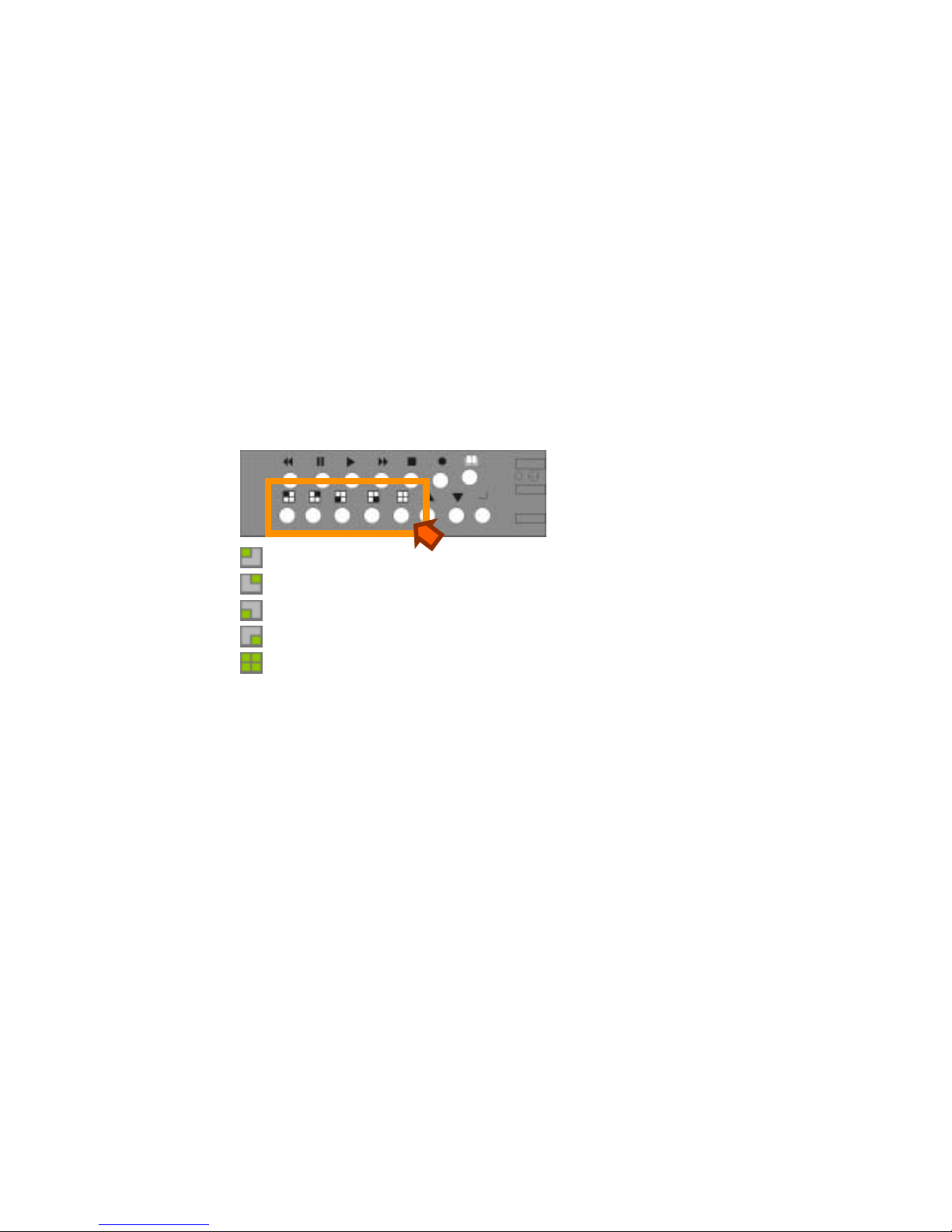
There are 5 display mode selection buttons on the DVR front panel.
: Channel 1 selection button
: Channel 2 selection button.
: Channel 3 selection button.
: Channel 4 selection button.
: All Channel selection button. – displays all 4 channels at the same time.
Basic Function
The basic functions include record (REC), and play (PLAY).
[NOTE] This chapter describes the BASIC DVR functions like recording, playing, fast forw arding, reverse, etc. For
more detailed descriptions on the DVR menu, please refer to the “Section C. DVR Menu” of this chapter.
iv. Record (!)
Start Recording
Press “!” button on the DVR front panel.
Then, you can see ‘"’ mark on channel screen, which means the channel is now recorded.
Stop Recording
Press stop, ‘!’, button, then the authorized password is requested. After the confirmation, the ‘"’ mark would
disappear.
[NOTE]: The password will be set as the default value (111111)
Page 5

-5-
v. Playback
Start Playing
Press “!” button on the DVR front panel.
Then, you can see the playback time selection menu as following:
.
[NOTE]: the unit will stop recording
upon Playback.
However, you can just simply press the “!” button once again to start playing.
Fast Forward (#)
To play the recorded stream faster, press “#” button.
There are three levels of fast forward playback speed.
# 1:(default) play one time faster (x1) than the normal play.
# 2:play two time faster (x2) than the normal play.
#3: play four times faster (x4) than the normal play.
#4: play thirty-two times faster (x32) than the normal play
#5: play sixty-four times faster (x64) than the normal play
To change the fast forward play back speed level, press the “#” again.
Reverse ( $)
To play the recorded stream backward, press “$” button.
[NOTE]: The reverse playback speed depends on the frame rate, the number of channel recorded, and
the record quality.
Pause (%)/Playback by one frame
To pause the video playback, press “%” button. Or to use “%” button to frame advance on
Pause mode.
Stop Playback
Press stop, ‘!’, button.
Note: Please press“!” button to exit to real-time display upon the end of the playback.
DVR Menu
There are four buttons for managing the DVR.
: To display menu option, press “MENU” " button.
: To change menu field or change the DVR configuration values, press up, “&,” or
down, “',” button.
: To select a menu item, change the DVR configuration values, or select a sub
menu, press “!” button.
SEARCH TIME
HARD DRIVE:HDD1
03/07/21 21:34:45 – 03/07/22
23:45:21
v 01 TIME 03/07/21 21:34:45
02 TIME 03/07/21 22:45:56
1. PRESS # key to switch
to searching by time
option.
2. press&' to move the
cursor
3. press! to change the
setting
4. press!to confirm the
selection and to play the
video
Page 6

-6-
T able on following p ages describes the DVR menu
Operating Instructions for the DVR Board
Below is a screen shot of the primary “Menu” page (the
“Camera and Record Control Menu). Press the “Menu”
button to display this menu.
MAIN MENU
>
CAMERA SELECT----
RECORD SELECT----
RECORD MODE EACH
RECORD FRAMERATE 25
VIDEO QUALITY NORMAL
RECORD SCHEDULE
SUB MENU
HARD DRIVE SETUP
SENSOR SETUP
PRESS (< , >) , THEN(! )
PRESS (") TO EXIT
MAIN MENU
Press the “"” key or the “#” key to move up or down the
indicator (V) on the menu.
1. In the main menu, the “>” indicator will be shown on the
screen right next to one of the seven different menu selection
CAMERA
SELECT
There are 4 cameras channels can connect to the DVR. Use
key button on the front panel to select the camera for real-time
viewing on the TV screen.
CH1 (Camera 1)
CH2 (Camera 2)
CH3 (Camera 3)
CH4 (Camera 4)
You can also use “SELECT ” button for different combinations
of camera viewing. For example,
When you choose ( - - - - ), all cameras will be disabled.
When you choose (1 2 3 4), all cameras will be operational.
When you choose ( - - - 4 ), only camera 4 will be operational.
When you choose (1 2 - 4), cameras 1, 2, and 4 will be
operational.
* There are 16 different combinations of channel settings.
RECORD
SELECT
Selecting camera channel on RECORD SELECT menu is as
same as CAMERA SELECT options.
Please remind that only selected camera will record real-time
events during recording period.
Page 7

-7-
RECORD
MODE
There two different record mode: 回 and 田
When you set as “回” mode, you can view each image
displayed in a single full screen by using the key buttons n the
front panel of the DVR box.
When you set as “田” mode, you can see the images from the
cameras in a quad screen, which shows four sections on the
single TV screen.
VIEW
CONTROL
In 回 mode, you can use the following key to see the
images from four different cameras in a full screen.
This View button controls FULL SCREEN display from
CH 1 (Camera 1)
This View button controls FULL SCREEN display from
CH 2 (Camera 2)
This View button controls FULL SCREEN display from
CH 3 (Camera 3)
This View button controls FULL SCREEN display from
CH 4 (Camera 4)
Quad screen: All images from 4 cameras are
displayed in 4 separate sections on a single screen.
RECORD
FRAMERATE
Factory default setting is 30, which means DVR records the
events at the speed of 30 shots of frames per second.
The higher the record frame rate is, the more natural look will
be displayed on the screen, while playback.
The lower the record frame rate is, the more you can save the
space on the hard disk drive.
There are 9 different record frame rate sets that you can
choose. (25fps,12fps,10fps,7fps,5fps,4fps,3f ps,2fps,1fps)
VIDEO
QUALITY
There are three different video quality settings: NORMAL,
LOW, HIGH
The higher the video quality is, the clearer images the unit
plays
The lower the video quality is, the more you can save the
space on the hard disk drive. (High: 50kbytes/frame,
Normal: 35kbytes/frame, Low:20kbytes/frame)
Page 8

-8-
You change a recording schedule during a day (24-hour
period) using this option. If the sensor device is attached to the
DVR, it will add additional function to your recording.
PROGRAMMED RECORD
+T T T T T T T T T T T T T T T T T+
| | | | |
0 3 6 9 12 15 18 21 24
PRESS (< , >) , THEN(SELECT)
PRESS (MENU) TO EXIT
RECORD
SCHEDULE
Number above indicate the time duration during 24-hour
recording period.
( T ) letter indicates non-stop automatic recording.
( A ) letter indicates sensor recording. It means that DVR starts
recording only when sensor device attached to the DVR
received movement signal in front of the camera.
( --) Nothing will be recorded during this period.
Note: $% buttons to move the indicator backward or forward.
! button to select different recording modes( the unit offers
non-stop recording, alarm recording and pause.)
SUB MENU
SUB MENU
> PASSWORD CHANGE
TIME SET
DATE DISPLAY FORMAT
PRESS (< , >) , THEN(SELECT)
PRESS (MENU) TO EXIT
PASSWORD
CHANGE
* Use the
view control
button on
the front
panel to
input the
number.
is “1”
is “2”
is “3”
is “4”
When you select, “PASSWORD CHANGE”, a password input
menu replaces the “Sub Menu”.
(The Factory Default Password is 111111)
You will be asked to input the following 3 pieces of information:
CURRENT PASSWORD : - - - - - NEW P ASSWORD : - - - - - PASSWORD CONFIRM : - - - - - -
When the new password is accepted, the board will flash the
following screen message:
Password changing !!!
The message will blink 5 times. Then the “SUB MENU” will
return.
If the password was not accepted, you will receive a message
that informs you. The “SUB MENU” returns. Y ou may try
again by repeating the same steps.
Page 9

-9-
TIME SET
You can change time/date/hour/year using TIME SET menu.
TIME
V
2003/01/01 01:01:00
PRESS (< , >) , THEN(SELECT)
PRESS (MENU) TO EXIT
[This represents year/month/day and hour/minute/second]
Use the “"” and “#” button on the front panel to move the
“ ^ “ cursor below the number back and forth. Then use the
“SELECT ” button to change the numeric values of date &
time.
DATE
DISPLAY
FORMAT
The unit provides yyyy/mm/dd and dd/mm/yyyy variants
which depend on regional preference
DATE DISPLAY FORMAT
YYYY/MM/DD
PRESS (< , >) , THEN(SELECT)
PRESS (MENU) TO EXIT
RECORD
CONTROL
When the “RECORD” button is pressed, the recording
process starts immediately. The recording channel
indicator ! next to CH1, CH2, CH3, CH4 appeared in the
center of the screen makes the user notified which camera
is running during recording period.
PLAYBACK
CONTROL
Playback Control:
When the “&” (Play) button is pressed, you will be
asked to input the time period for which you are recalling
recorded video.
Press the “&” (Play) button again to view the recorded
video.
You may use the “View” button (during playback) to select
the cameras that you desire to display on the monitor. Full
screen playback is available only when the camera record
selection Is “Each.”
To pause playback, press the “%” key.
To back up a playback 10 seconds, press the “$” key.
To play X3 way, press the “#” key.
Page 10

-10-
HARD DRIVE SETUP
OVERWRITE ENABLED YES
MASTER HDD SIZE 40000 MB
MASTER HDD USED 0 MB 0 %
MASTER HDD FORMAT
SLAVE HDD SIZE Not Used
SLAVE HDD USED 0 MB 0%
SLAVE HDD FORMAT
PRESS (< , >) , THEN(SELECT)
PRESS (MENU) TO EXIT
Note: The unit features one hard disk only!
HARD
DRIVE
SETUP
1. OVERWRITE ENABLED:
If you choose YES, recording continues and overwrites the
previous recording when hard disk drive space is full. If you
choose NO, the recording session stops when all hard disk
drive is full for recording.
2. MASTER HDD SIZE:
It shows the size of the primary hard disk drive installed in
the DVR.
3. MASTER HDD USED:
It shows the space used on the first hard disk drive for
recording.
4. MASTER HDD FORMAT:
If you format the hard drive, it will erase all the data recorded
on the first hard disk drive.
Page 11

-11-
You will be prompted to input a password upon HDD
FORMAT’S option.
HARD
DISK
FORMAT
PASSWORD INPUT (6) : _ _ _ _ _
SENSOR
SETUP
SENSOR SETUP
SENSOR RECORD TIME 15
ALARM OUT TIME 05
CHANNEL-1 NOT INSTALLED
CHANNEL-2 NOT INSTALLED
CHANNEL-3 NOT INSTALLED
CHANNEL-4 NOT INSTALLED
PRESS ( < , >) , THEN(SELECT)
PRESS (MENU) TO EXIT
Note: After alarm installation, please go to
“ RECORD SCHEDULE” to select “A” (alarm record) as
record mode in the specified period of time, so that the
unit will accordingly start recording upon alarming
during the specified time.
Page 12

-12-
1. SENSOR RECORD TIME
Sensor indicates the movements in front of the
camera.
2. ALARM OUT TIME
It controls how long (in seconds) the alarm lasts after it
sets off.
3. There are 3 different mode for sensor setting:
NOT INSTALLED, NORMAL-CLOSE and NORMALOPEN.
CHANNEL-1 TYPE: NORMALCLOSE
CHANNEL-2 TYPE: NORMALOPEN
CHANNEL-3 TYPE: NORMALCLOSE
CHANNEL-4 TYPE: NORMAL-
OPEN
In NORMAL-OPEN mode, if the cable line connected
to the sensor through DVR is cut off by an intruder , the
sensor recording starts. In NORMAL-CLOSE mode,
the cable line connected to the sensor through DVR is
cut off by an intruder , the sensor recording doesn’t
start.
NOTE
1. RESET (Initialization): To make the board to reset.
Press “%” button 5 times in the normal view mode.
Be aware that all the information (including the password)
will be lost. After reset, the password will be set as the
default value (111111)
Page 13

-13-
2. DVR installation
Connect T o Your TV Set
To display the DVR picture, the DVR’s video output signal should be transferred to your TV set. Any TV set
which has video input terminal would be suitable for displaying the picture. The next figure shows the video
signal line connection.
Camera Installation
The DVR can support up to 4 cameras at the same time. The camera installation procedures are as follows.
There’re two simple steps for the installation of the camera(s).
i. Connect the Video Signal Line
Connect the video signal line to the DVR.
ii. Connect the camera power line
Connect the camera adaptor jack to the camera, and plug in the adaptor.
The completed connection for a camera would be as figure shown below.
Page 14

-14-
C. Sensor Installation
The DVR has 4 sensor input for 4 channel. The sensor installation procedures are as follows. There’re two
simple steps for the installation of the camera(s).
# Connect the sensor signal line.
# Connect the sensor power line.
iii. Connect the sensor signal line
Connect the video signal line to the DVR. The sensor signal input terminal is at the DVR back panel.
[NOTE] Two lines are used for one sensor.
iv. Connect the sensor power line
Connect the sensor adaptor jack into the sensor, and plug in the adaptor.
Following figure is the picture of the sensor input terminal after connecting sensor input lines. (In the read
box)
In the picture above, 3 sensors, for the channel 1,2 and 3, are connected to the DVR.
Now the sensor is ready to let DVR know if there’s any movement.
Ch1 ch2 ch3 ch4 alarm out
Page 15

-15-
Alarm Installation
The DVR has 1 internal switch for sounding alarm when the sensor is activated due to the unwanted entrance
of anonymous visitor. The switch is open at normal state, but, when the alarm is activated, the switch is closed
so that the alarm gets the power. The circuitry is as follows.
And the following picture is the alarm switch terminal which is at the DVR back panel.
The alarm installation procedures are as follows. There are two simple steps for the installation of an alarm.
# Prepare the power supply.
# Connect the alarm power line.
v. Prepare the power supply.
As seen in the figure of the alarm circuitry above, the alarm needs a power supply. Normally, the power supply
comes with the alarm.
vi. Connect the alarm power line.
Following figure is the picture of the alarm power lines are connected to the DVR alarm switch terminal. (In the
read box)
Page 16

-16-
Appendix.
I. Regulatory
FCC Certification
This equipment has been tested and found to comply with the limits for a class A digital device,
pursuant to Part 15 of the FCC rules. These limits are designed to provide reasonable protection
against harmful interference when the equipment is operated in a commercial environment. This
equipment generates, uses, and can radiate radio frequency energy and, if not installed and used in
accordance with the instruction manual, may cause harmful interference to radio communications.
Operation of this equipment in a residential area is likely to cause harmful interference in which case
the user will be required to correct the interference at the own expense.
CE Mark
This product is marked with the CE symbol and indicates compliance with all applicable directives.
Appendix
II. Reference on HDD capacity
The table below indicates the recording rates for different image quality with a 80HDD:
Appendix
III. Built-in HDD installation
Please take notice that the flat
cable and power line be correctly
connected to the system
Please place HDD in rack and
fasten each screw exactly.
Note: Please make sure the
exact jumper-setting of HDD
before the installation.
(Please refer to HDD’s master
j
umper-setting.)
In terms of system’s stability,
Maxtor and Segate are kindly
recommended !
1 2 3 4 5 7 10 15 30
High 616hr 308hr 205hr 154hr 123hr 88hr 62hr 41hr 21hr
Normal 812hr 406hr 271hr 203hr 162hr 116hr 81hr 54hr 27hr
MUX
Basic 976hr 488hr 325hr 244hr 195hr 130hr 98hr 65hr 33hr
High 439hr 220hr 146hr 110hr 88hr 63hr 44hr 29hr 15hr
Normal 641hr 321hr 214hr 160hr 128hr 92hr 64hr 43hr 21hr
Quad
Basic 786hr 393hr 262hr 197hr 157hr 112hr 79hr 52hr 26hr
 Loading...