

Page 1
15-WP16-USB
16CH Digital Video Recorder
User’s Manual
May, ‘2005
Version_1.0
PDF created with pdfFactory trial version www.pdffactory.com
Page 2
RISK OF ELECTRIC SHOCK DO NOT OPEN
CAUTION
CAUTION: TO REDUCE THE RISK OF ELECTRIC SHOCK, DO NOT REMOVE COVER (OR BACK)
NO USER-SERVICEABLE PARTS INSIDE. REFER SERVICING TO QUALIFIED SERVICE
PERSONNEL.
SAFETY PRECAUTIONS
This label may appear on the rear of the unit due to space limitations.
The lightning flash with arrow point symbol, within an equilateral triangle, is
intended to alert the userto the presence of uninsulated “dangerous voltage”
within the product’s enclosure that may be of sufficient magnitude to
constitute a risk of electric shock to persons.
The exclamation point within an equilateral triangle is intended to alert the
user to the presence of importance operating and maintenance (servicing)
instructions in the literature accompanying the appliance.
Warning
To reduce the risk of fire or electric shock, Do not expose thisproduct to rain or moisture.
Do not insert any metallic object through ventilation grills.
Power disconnect : Units with or without ON-OFF switches have power
supplied to the unit whenever the power cord is inserted into the main source;
However, the unit is operational only when the ON-OFF switch is in the ON
position. To disconnect it from the main source, you have to disconnect the
Power cord.
PDF created with pdfFactory trial version www.pdffactory.com
Page 3

Table of Contents
I. Introduction
1. Package Contents
2. Features
3. Front Panel and Rear Panel Connection
II. Installation
1. Front Panel
2. Rear Panel
3. Menu Tree
III. Main MENU Programming
1. OverviewMain Menu
2. SYSTEM SETUP
3. DISPLAY SETUP
4. RECORDING SETUP
5. ALARM SETUP
6. MOTION SETUP
7. WEEKLY SETUP
8. NETWORK SETUP
9. ARCHIVING
10. HDD INFORMATION
11. SEARCH LIST
12. DISPLAY Mode
13. RECORDING Mode
14. PLAYBACK Mode
IV. Software Upgrade Procedure
APPENDIX 1. Specification
2. Pin Description of connectors
PDF created with pdfFactory trial version www.pdffactory.com
Page 4
I. Introduction
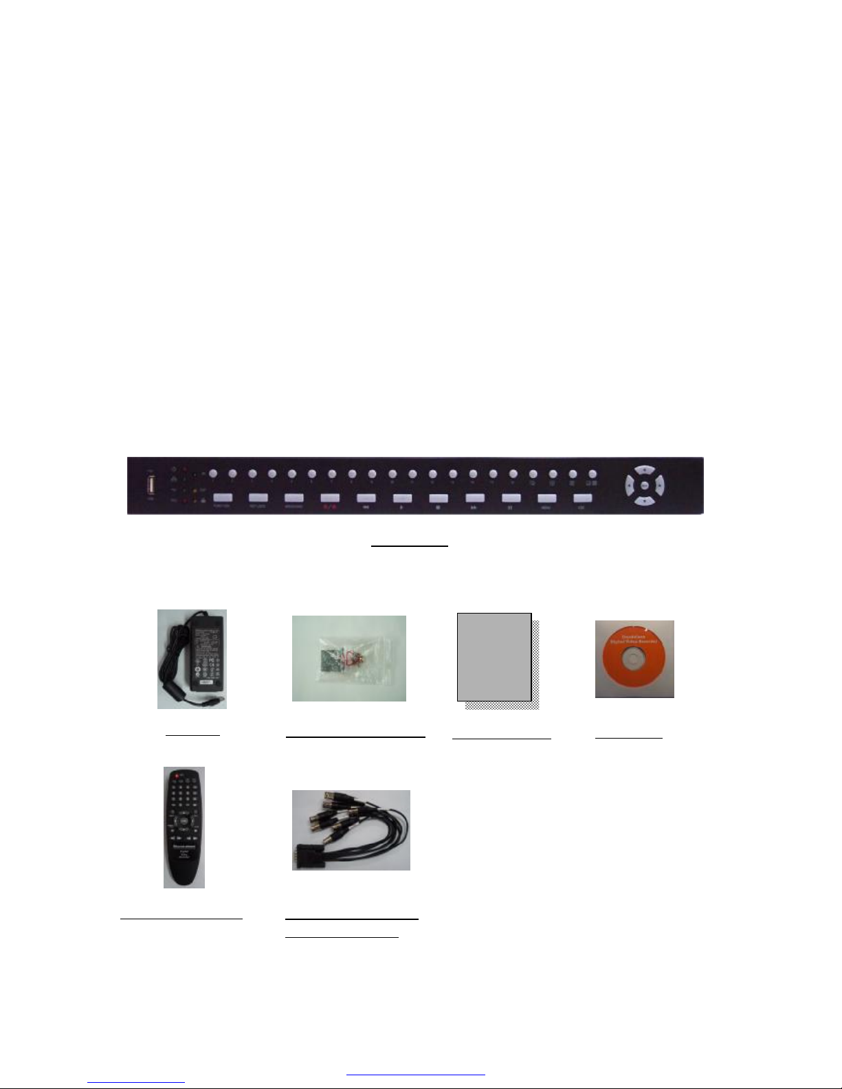
1. Package Content
Verify that the following contents are contained.
l 1 x 16CH DVR
l 1 x Adapter (12V/5A)
l 2 x Rack Mount Bracket
l 1 x User’s manual
l 1 x Remote controller
l 1 x Install CD
l 2 x 8CH BNC cable harness for loop through video output.
l 1 x 250MB Memory Stick
16CH DVR
Adapter
Rack Mount Bracket
Install CD
User’s Manual
BNC cable harness
for loop through
User
Manual
Remote controller
PDF created with pdfFactory trial version www.pdffactory.com
Page 5

2. Features
This DVR provides recording capabilities for 16 camera inputs. It provides playback
or live display and network function while in recording mode. And also it offers the
following features:
u 16 Composite Input Connectors/ 16 Loop-Through Video Connectors
- Compatible with Color ( PAL) and B&W (CCIR) Video
u Display and Record Video Resolution
-Display Resolution: PAL (720x288) real time display
-Display mode: Full, QUAD, 8/9/10/16 picture display mode and Sequential Image
Display
u Compression: M-JPEG
- Standard image, high quality; 16KB / field
u Multiple Search Categories (Date/Time, Event, Manual, Schedule)
u Records up to 50 PAL frames per Second
-Normal Recording: 16CH multiplexing recording with 720x288 at field mode.
-Alarm, Motion recording: 1CH recording at 1 alarm, 1 motion, 16CH multiplexing
recording at other conditions.
u Continuous Recording in Disk Overwrite Mode
u Simultaneously Record, Playback and Network
u Archiving using USB Memory Drive or USB HDD
-USB 1.1 Storage Class support
u User-friendly Graphical User Interface (GUI)
u Manual/ Schedule and alarm/ motion recording Modes (Time and Event)
u 16 Alarm input Connections, 4 relay output connection
u Network Function
- Dynamic IP or Static IP, DHCP, Floating IP support
-Live or Recorded Video Access via Ethernet
-DDNS client support
u Audio Recording and Playback
-1ch audio support
PDF created with pdfFactory trial version www.pdffactory.com
Page 6
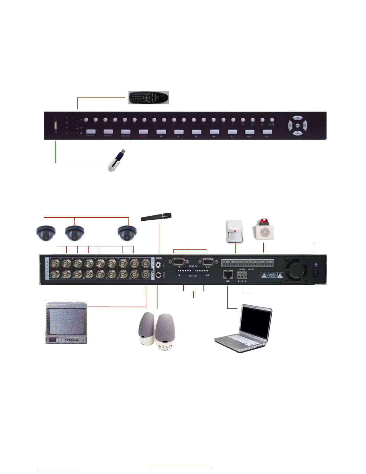
3. Front Panel and Rear Panel Connection
USB Memory
Drive
Monitor & Spot
Speaker
Microphone
Alarm
Output
Sensor
Input
Ethernet
Cameras
Pan / Tilt / Zoom
Adaptor
(12V/ 5A)
••••• Video Out (16CH)
for Loop Through
75 Ohm
Terminator
Remote
controller
PDF created with pdfFactory trial version www.pdffactory.com
Page 7
II. INSTALLATION
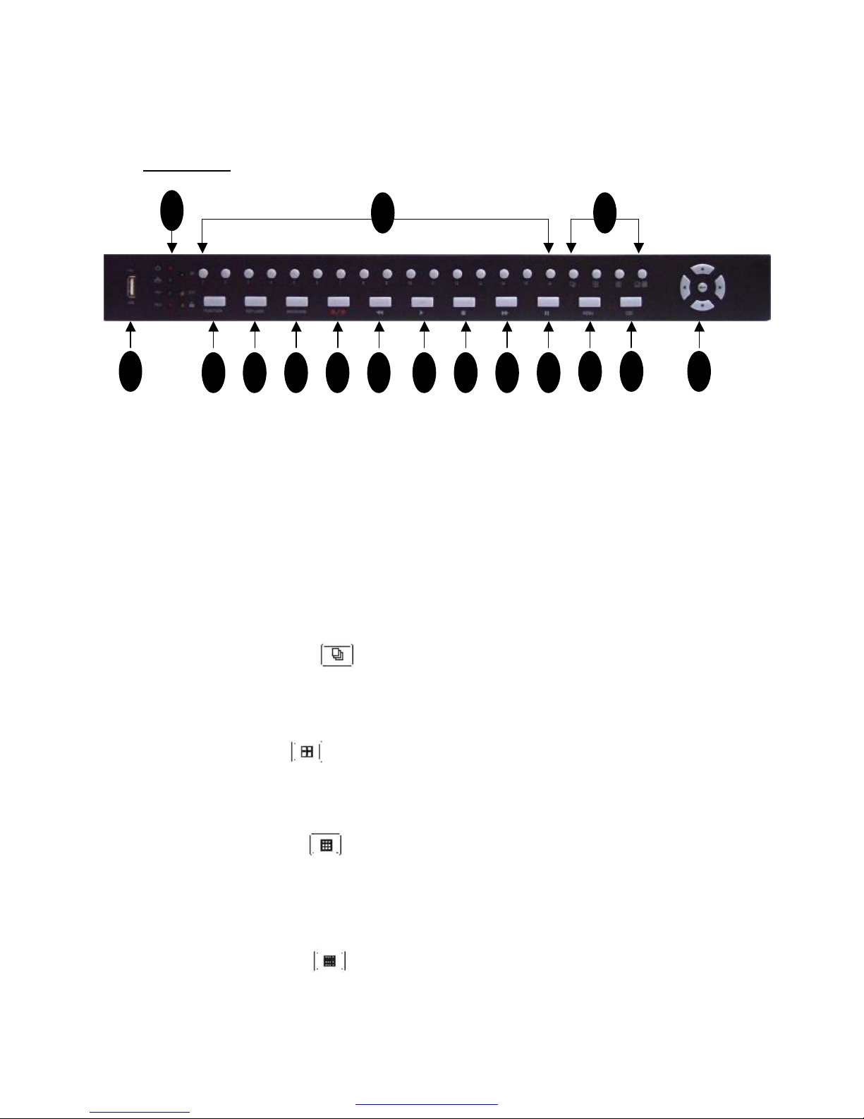
Front Panel
1. USB port
A USB port is provided to connect external USB memory drive for archiving video.
2. Video Display Channel Selection buttons
Channel button from CH1 to CH16 is to select video channel displayed on monitor.
3. Video Display mode selection buttons
There are four kinds of video display modes which consists of sequential display,
QUAD, 9CH, 16CH display mode.
Full Picture Display mode: Full picture can be selected by channel selection button
from CH1 to CH16.
Sequential Display mode:
If this button is pressed under given video display mode, each video display mode
is switched sequentially. For example, if this button is pressedin QUAD mode,
QUAD picture is switched sequentially from CH1-4, CH5-8 to CH13-16.
QUAD Display mode:
If QUAD button is pressed, QUAD picture will be displayed. Whenever this button
is pressed, QUAD picture including CH1 to CH4, CH5 to CH8, CH9 to CH12 and
CH13 to Ch16 will be changed in turn.
9 Picture Display mode:
If 9 picture display button is pressed initially, 9 picture with CH1 to CH9 will be
displayed. The coming 9 picture with CH8 to CH16 will be displayed by pressing
this button one more. Whenever this button is pressed, 9 pictureis switched in turn
from (to) CH1 –CH9 to (from) CH8 -CH16.
16 Picture Display mode:
Whenever 16 picture display button is pressed, picture display mode will be
changed from 16 picture display to 1+7 display mode, 2+8 displaymode.
1
2 3
4 5 6 7 8 9 1110 12
1413 15
16
PDF created with pdfFactory trial version www.pdffactory.com
Page 8

4. FUNCTION
The main picture in 1+7, 2+8 display of 16 picture display mode can be changed by the
combination of FUNCTION and channel selection button. Main picture can be changed
by channel selection button from CH1 to CH16 after pressing FUNCTION button.
5. KEY LOCK
In order for only authorized person to operate buttons in frontpanel, this LOCK button
can be utilized. If this button is pressed, all of buttons in front panel are not operated with
yellow LOCK LED. To release buttons LOCK, password will be requested just after
pressing LOCK button. If correct password is input, button LOCK will be released.
6. Archiving button
Whenever ARCHIVE button is pressed, archiving will be started.
7. REC/ STOP button
Press REC (Red circle) to begin record. Press REC to stop recording again.
This is toggle button.
8. REW (◀◀)
Press REW to perform high speed backward playback. It support 2 to 16 times
playback speed.
9. PLAY button (▶) and 10. STOP button
If PLAY (▶) is pressed, search lists will be displayed on monitor. After selecting one
recorded file among lists, playback will be started by PLAY button. To stop playback,
STOP button is used. While DVR is in high speed playback mode like FF or REW, it
return to playback by PLAY button.
11. FF (▶▶)
Press FF to perform high speed forward playback. It support2 to 32 times playback
speed.
12. PAUSE
Press PAUSE to pause playback. This PAUSE button can be used forbackward or
forward movement by one field. The direction of field movement is decided by
pressing FF or REW previously.
13. MENU
Press MENU button to enter menu system.
14. ESC
ESC button is used to return upper menu and to save set-up parameter at the same
time .
PDF created with pdfFactory trial version www.pdffactory.com
Page 9
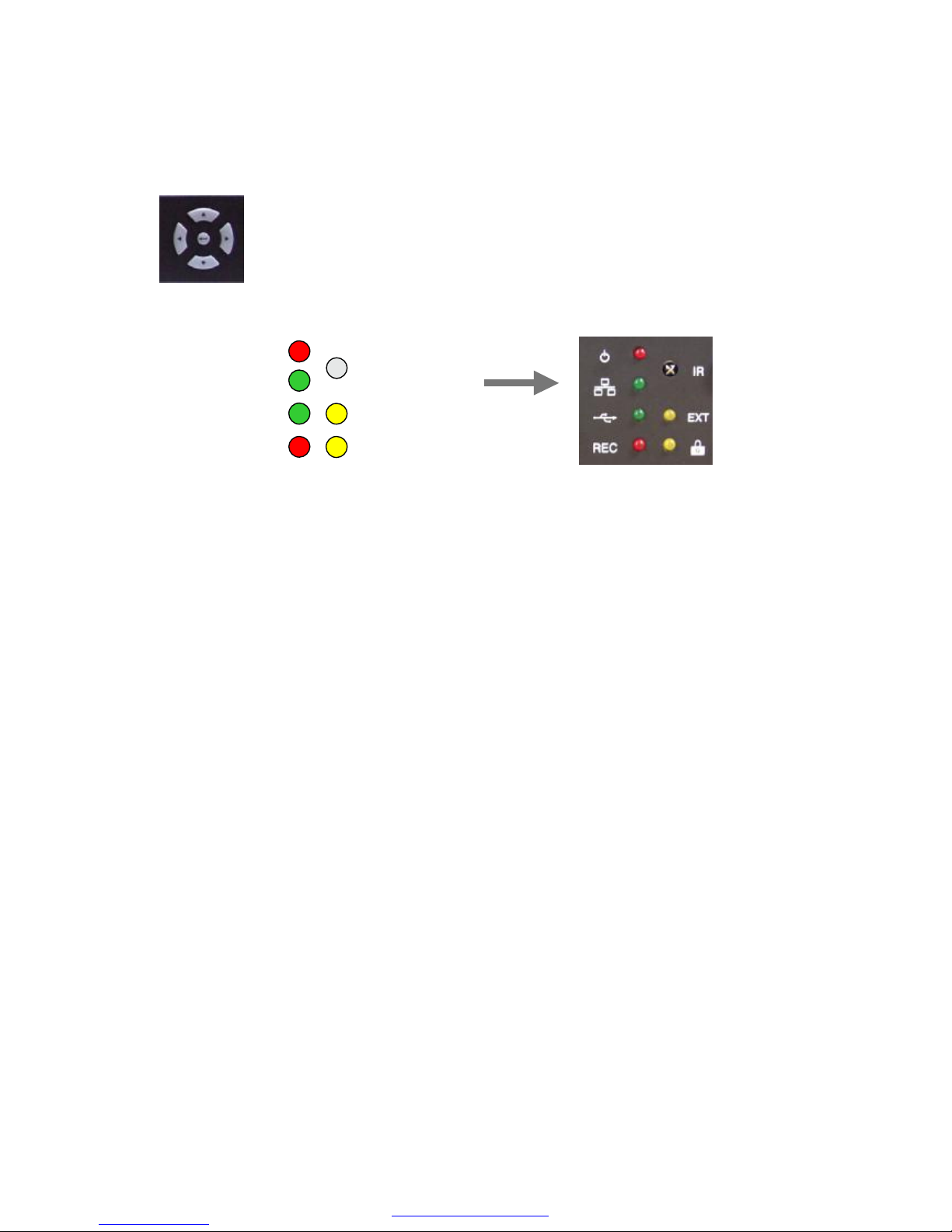
15. Direction button and Enter Button
Direction buttons are used to move LEFT, RIGHT, UP and DOWN in menu. They also
can be used to input password. ENTER button is used to save parameter,
to select parameter in the menu. And also in playback it is used to select
one of listed file for playback after searching recorded files by all, time,
alarm, motion, manual and so on.
16 LED Indicators
1) POWER LED
This red LED turns “ON”when Power is “ON”.
2) NETWORK indication LED
This green LED will turn “ON”, while data communication is working through
network.
3) Archiving LED
This green LED will turn “ON”, while data archiving is working through USB
Memory driver.
4) REC
This red LED will turn “ON”during recording.
5) EXT:
This yellow LED will turn “ON”, when external alarms are triggered or motions are
detected.
6) LOCK
This yellow LED will turn “ON”while LOCK button is working.
7) Remote Controller receiver.
Remote controller sensor input window
POWER
NETWORK
USB Archiving
REC
EXT
LOCK
REMOCON
PDF created with pdfFactory trial version www.pdffactory.com
Page 10
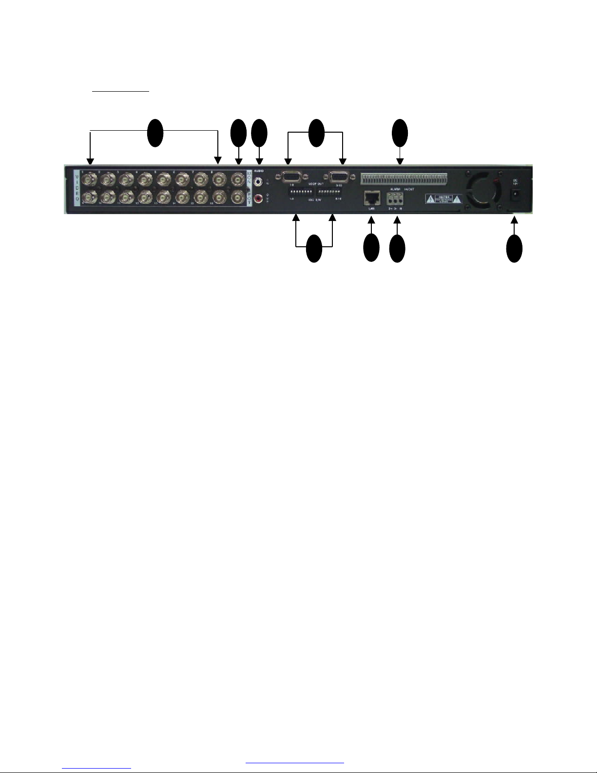
1. 16CH Video Input: 16 channel composite video inputs with BNC connectors
Since this DVR automatically detects video format (NTSC or PAL) as soon as power is
ON, NTSC or PAL video sources can be connected in DVR. But NTSC and PAL video
sources for 16CH video inputs can not be mixed. If they are mixed, DVR can’not be
operated properly.
2. 2CH Video Output
One video output (Upper BNC) is used to monitor live, playback pictures. The other
(lower BNC) is used to monitor SPOT monitoring which displays all of connected video
channels sequentially.
3. Audio input (upper RCA) and Output (Lower RCA)
Unbalanced audio signal input and output with RCA jack. Connectthe audio source to
audio input, audio output to your amplifier because the DVR does not have amplified
audio output. A speaker with an amplifier will be needed foraudio playback.. The audio
input can be from an amplified source or directly from a microphone.
4. 16CH Loop through outputs: 16 channel composite video outputs with D-SUB
connectors. If the connection of loop-through video outputs into another video
equipments is requested, 16CH Loop-Through outputs can be utilized for it. If loopthrough video outputs will be connected to another video equipments, 75 Ohm
termination switch should be “OFF”. Then, another video equipments should be 75 ohm
terminated.
5. 75 Ohm Termination Switch
If you want to connect loop-through video outputs into another video equipments,
75 Ohm termination switch should be “OFF”. Then, another video equipments should
be 75 ohm terminated. If loop through video outputs are not connected to another
video equipments, it should be “ON”.
If 75 Ohm termination switch “ON”or “OFF”is changed, it will cause poor video quality.
Rear Panel
1 2 3
5
6
7
8 9
4
PDF created with pdfFactory trial version www.pdffactory.com
Page 11

6. Alarm input and relay output: (16 alarm inputs and 4 relay output with NO, NC)
To make secure connections on the Alarm Connector Strip, press and hold the button
and insert the wire in the hole below of connector pin. After releasing the pin, pull
gently on the wire to make certain it is connected. To disconnect a wire, press and
hold the connector pin above the wire and pull out the wire.
16 Alarm Inputs: 1,2,3,4,…, 16,G(Ground)
You can use external devices to signal the DVR responding toevents. Mechanical or
electrical switches can be wired to the Alarm Inputs and GND(Ground) connectors.
The threshold voltage is 4.3V and should be stable at least 0.5 seconds to be detected.
G (Ground), COM (common): G is same as common.
Connect the ground side of the Alarm input to G (Ground). Connect the ground side of
relay output to COM connector.
4 Relay output:
4 relay output with NO or NC can be sent to external device.You can select NO or NC
, according to characteristic of mechanical or electrical switch.
7. Ethernet Port: RJ45 jack
Connect a Cat5 cable with an RJ-45 jack to the DVR connector. Remote PC viewer
software via network enable you to live viewing or searching.
8. RS485 serial port
An RS485 port is provided to connect to speed domes.
9. Power Input (from Adapter)
Connect the adaptor to the DVR for DC power supply. (DC 12V/5A).
PDF created with pdfFactory trial version www.pdffactory.com
Page 12
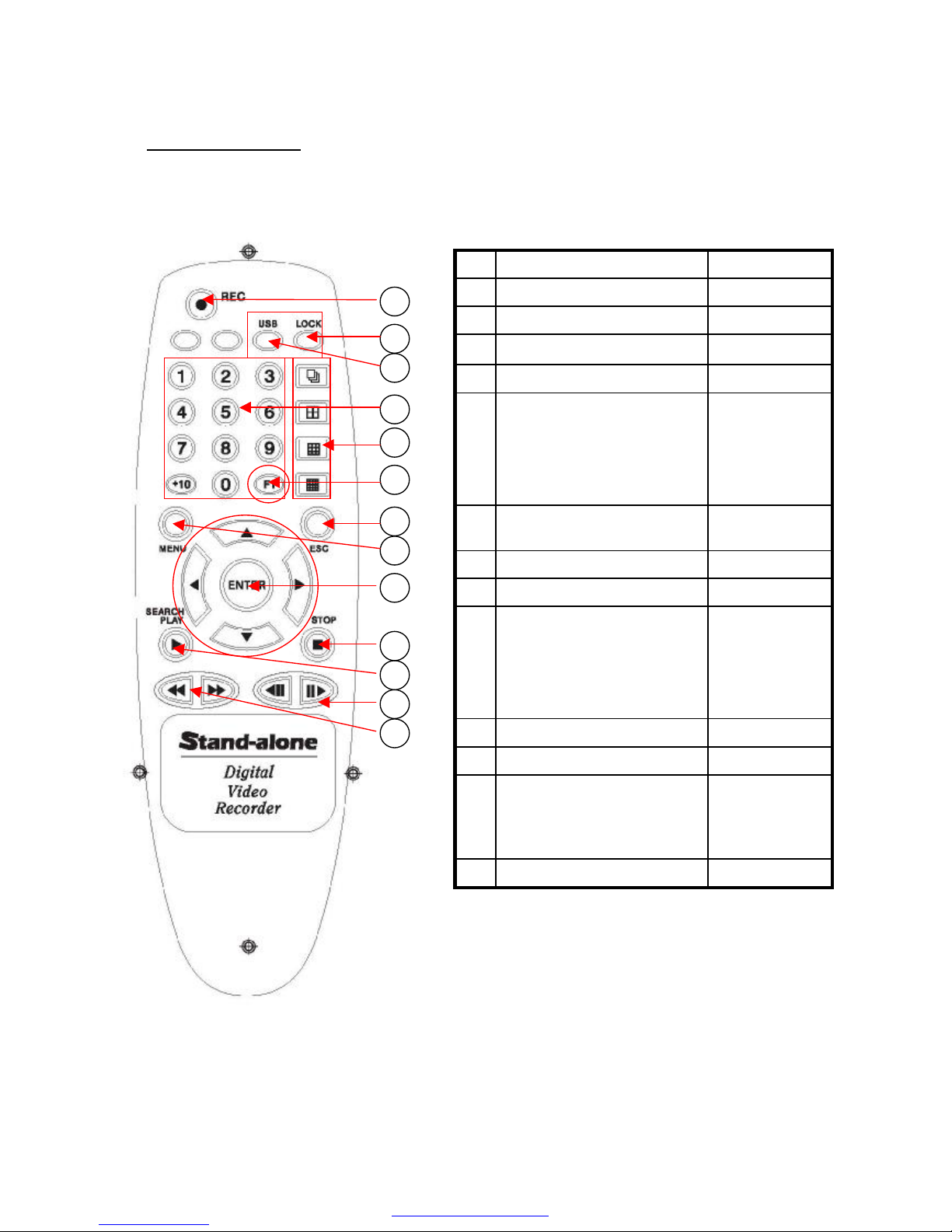
USBArchiving Start button3
FF, REWFast Playback buttons13
Movement
forward or
backward
by 1 Field.
PAUSE/ 1 field movement
backward.
PAUSE/ 1 field movement
forward.
12
Search/ PLAYPlayback Start button11
STOPPlayback Stop button10
Direction
(Password
Number Input)
and
ENTER buttons
1) UP (▲)
2) DOWN (▼)
3) LEFT (◀)
4) RIGHT (▶)
5) ENTER
9
MENUMovement to menu mode8
ESCMovement to upper menu7
FunctionMain picture selection button
in 8. 10 picture display mode
6
Video Picture
Display mode
1) Sequential display button
2) QUAD display button
3) 9 picture display button
4) 16/ 8/ 10 picture display
button
5
1,2,3,…,0, +10Video CH selection buttons4
LOCKButton LOCK Enable/Disable2
RECRecording Start/ Stop button1
Button NameDescriptionNo
Remote Controller
1
2
3
4
7
8
10
5
11
9
12
13
6
< Button Description >
< Remote Controller buttons >
PDF created with pdfFactory trial version www.pdffactory.com
Page 13

Menu Tree
ALARM SETUP4
SYSTEM SETUP1
HDD INFORMATION9
ARCHIVING8
NETWORK SETUP7
WEEKLY SCHEDULE6
MOTION SETUP5
RECORDING SETUP3
DISPLAY SETUP2
MAIN MENU
VIDEO FORMAT
PASSWORD
ADMIN LOCK
TIME FORMAT
DATE FORMAT
DATE/TIME SET
DEFAULT
REV STATUS
2
3
4
5
6
7
8
9
LANGUAGE 1
SYSTEM SETUP
QUALITY 1
FRAME RATE
AUDIO
STOP KEY
CAMERA NUM
RECORD
2
3
4
5
RECORDING SETUP
SENSITIVITY 1
FRAME RATE
DURATION
CAM NUM
AREA SETTING
TRIGGER OUT
BUZZER ALERT
2
3
4
5
MOTION SETUP
00: 00
00: 00
00: 00
00: 00
00: 00
00: 00
NONE
00: 00
WEEK START DURATION
00: 00SUN
00: 00
00: 00
00: 00
00: 00
00: 00
00: 00
NONE
MON
TUE
WED
THU
FRI
SAT
HOLIDAY
WEEKLY SCHEDULE
CONNECT 1
IP ADD
SUB NET
GATE WAY
DNS
PORT
NTP TIME
TIME ZONE
DDNS STATUS
2
3
4
5
6
7
8
9
NETWORK SETUP
ARCHIVING TYPE 1
ARCHIVING TIME
ARCHIVE INFO
NAME: / TOTAL:
ARCHIVE LOG
2
3
4
ARCHIVING
HARD DISK 1
TOTAL
FREE
FORMAT HDD
OVERWRITE
2
3
HDD INFORMATION
BRIGHTNESS
CONTRAST
PTZ TYPE
SEQ DWELL TIME
SPOT DWELL
TIME/DATE OSD
CAM NUMBER OSD
VIDEO LOSS OSD
POP-UP DISPLAY
POSITION
2
3
4
5
6
7
8
ADJUST CHANNEL1
DISPLAY SETUP
FRAME RATE 1
DURATION
SENSOR TYPE
ALARM INPUT
TRIGGER OUT
BUZZER ALERT
2
3
4
5
ALARM SETUP
PDF created with pdfFactory trial version www.pdffactory.com
Page 14

NOTE:
To access the DVR Main Menu, press MENU. To escape MENU, ESC button is also
used. Buttons for movement in Menu are ◀ or ▶. Button for selection is ENTER, Buttons
for increasing or decreasing parameter are ▲ or ▼. Press ESC to return to the previous
MENU after setting and to save the values of setup.
ç ◀(LEFT), ▶(RIGHT), ▲(UP), ▼(DOWN) and ENTER buttons.
III. Main Menu Programming
1. Overview Main Menu
Before using your DVR for the first time, you will want to establish the initial settings.
This includes items such as time and date, password, display, record mode, network
and so on.
In order to program Main Menu, first press MENU button of front panel in DVR.
If ADMIN LOCK is set as YES (factory default is YES), below figure will be appeared.
PASSWORD
*
****
PASSWORD LOGIN
▲▼◀▶ EXIT
ENTER
Then input password number using 1, 2, 3,
4 Channel Buttons (Factory default is to
press “1”button 4 times), and press
ENTER button. MAIN MENU will be
appeared.
< MAIN MENU >
MOTION SETUP5
SYSTEM SETUP1
HDD INFORMATION9
ARCHIVING8
NETWORK SETUP7
WEEKLY SCHEDULE6
ALARM SETUP4
RECORDING SETUP3
DISPLAY SETUP2
MAIN MENU
▲▼◀▶ EXIT
ENTER
PDF created with pdfFactory trial version www.pdffactory.com
Page 15

2. SYSTEM SETUP
To access SYSTEM SETUP, press ENTER button after moving highlight bar to
SYSTEM SETUP in MAIN MENU. Below menu will appear on monitor.
1) LANG : Language Selection
The languages supported are English, Chinese, Japanese.
2) VIDEO FORMAT: NTSC/ PAL
Video format is automatically detected after power ON. The detected video information
will be displayed on VIDEO FORMAT. User don’t need to change video format.
3) PASSWORD:
Move Highlight bar to PASSWORD in the SYSTEM Menu using DOWN or UP button .
And then press ENTER to change password. For four digit password input, “1”, “2”, “3”
and “4”buttons can be used.
NOTE: Factory Default is “Pressing 1 channel button four times”.
REV STATUS : VERSION
1 : 1 : 2
9
: NTSCVIDEO FORMAT 2
DEFAULT : YES / NO8
:
: MM-DD-YY
: 24HOURS
: YES
: ****
: ENG/CHNLANGUAGE1
05: 20: 2005 10:50:11
DATE/TIME SET7
DATE FORMAT6
TIME FORMAT5
ADMIN LOCK4
PASSWORD3
SYSTEM SETUP
1
▲▼◀▶ EXIT
ENTER
PDF created with pdfFactory trial version www.pdffactory.com
Page 16

OLD**** PASSWORD2
SYSTEM SETUP
NEW**** PASSWORD2
SYSTEM SETUP
AGN**** PASSWORD2
SYSTEM SETUP
Input old password. (Factory Default is
“Pressing “1”button four times”.)
Input new password. Enter the password by
pressing the appropriate combination of four
number, “1”, “2”, “3”, “4”buttons.
Input new password again to confirm new
password.
4) ADMIN LOCK: YES/ NO
Move Highlight bar to ADMIN LOCK in the SYSTEM Menu using DOWN or UP button .
If ADMIN LOCK is selected as YES by LEFT or RIGHT, password is requested
whenever entering menu. If NO, password isn’t requested.
5) TIME FORMAT: 24/ 12 HOURS
Move Highlight bar to TIME FORMAT in the SYSTEM Menu using DOWN or UP button
and press the LEFT or RIGHT button to select 24 HOURS (military time) or 12 HOURS
(AM/PM). Whenever Time Format is changed, clock information on monitor and file
information in search list will be changed together.
6) DATE FORMAT: MM-DD-YY/ DD-MM-YY/ MM-DD-YY
Move Highlight bar to DATE FORMAT in the SYSTEM Menu using DOWN or UP
button. Date format can be changed using LEFT or RIGHT button.
7) DATE/ TIME SET:
Move Highlight bar to DATE/TIME SET in the SYSTEM Menu using DOWN or UP
button. And then press ENTER to set the time.
NOTE:
1. If you set a date and time that is older than some of yourrecorded
images, it is not easy to manage recorded files.
2. Before starting your DVR, DATE/ TIME should be setting properly.
PDF created with pdfFactory trial version www.pdffactory.com
Page 17

2004:01:11 10:50:11
DATE/TIME SET6
SYSTEM SETUP
2004:01:11 10:50:11
DATE/TIME SET6
SYSTEM SETUP
2004:01:11 10:50:11
DATE/TIME SET6
SYSTEM SETUP
2004:01:11 10:50:11
DATE/TIME SET6
SYSTEM SETUP
…
Year is changed by DOWN or UP button.
By LEFT or RIGHT button.
Month is changed by DOWN or UP button.
LEFT or RIGHT button.
Date is changed by DOWN or UP button.
LEFT or RIGHT button.
Time is changed by DOWN or UP button.
To confirm DATE/TIME setting, ENTER
button should be pressed.
After setting DATE/ TIME, ESC or ENTER button can be used in order to return upper
Menu.
8) DEFAULT: Return to factory default mode.
9)REVISION STATUS
It shows DVR software version. Whenever upgrading software, upgraded version will
be displayed.
PDF created with pdfFactory trial version www.pdffactory.com
Page 18

3. DISPLAY SETUP
To access DISPLAY SETUP, press ENTER button after moving highlight bar to
DISPLAY SETUP in MAIN MENU. Above menu will appear on monitor.
1) ADJUST CHANNEL: CH1, CH2, CH3, CH4
The camera channel to adjust brightness, contrast can be selected by ADJUST
CHANNEL using LEFT or RIGHT button.
BRIGHTNESS: 1 to 99 %
BRIGHTNESS can be changed using LEFT or RIGHT button.
-NOTE: Minimum value is 1 (very dark), maximum value is 99 (verybright).
CONTRAST: 1 to 99 %
CONTRAST can be changed using LEFT or RIGHT button.
PTZ TYPE (Pan, Tilt and zooming protocol selection)
The high end camera(s) with panning, tilting and zooming function would be
connected with some of video inputs. The camera(s) has(have) its own control
protocol to control panning, tilting and zooming, accordingto PTZ camera
manufacturer.
1-60 SECSPOT DWELL3
ON/ OFFPOP-UP DISPLAY7
ON/ OFFVIDEO LOSS OSD6
ON/ OFFCAM NUMBER OSD5
ON/ OFFTIME/ DATE OSD4
NONE, 1-60 SECSEQ DWELL TIME2
1-99 %BRIGHTNESS
1-99 %
CH1, CH2, …, CH16ADJUST CHANNEL1
POSITION8
PTZ TYPE
CONTRAST
DISPLAY SETUP
▲▼◀▶ EXIT
ENTER
2
PDF created with pdfFactory trial version www.pdffactory.com
Page 19

In order to control PTZ of the camera from remote area by network viewer software,
proper PTZ TYPE should be selected in here. Your DVR supportsover ten PTZ
cameras. According to customer requirements, PTZ control will be added in it.
* NOTE: PTZ stands for pan, tilt and zooming.
* PTZ protocols: Panasonic/ Pelco-D/ PelcoP/ Techwin/ Niko/ DRX502A_DSC230s
/KRE_301_302/GC_755_NP/ TOA_CC554/ RAS716LSand so on.
2) SEQ DEWLL TIME:NONE/ 1 to 60 seconds.
SEQ DWELL TIME can be changed using LEFT or RIGHT button.
-NOTE: It is just reflected in sequential display mode.
3) SPOT DWELL: 1 to 60 seconds.
SPOT DWELL TIME can be changed using LEFT or RIGHT button. All of video channels
connected with video inputs of DVR are sequentially switched for video output for
SPOT monitoring.
4) TIME/DATE OSD: ON/ OFF
When it is set as OFF, characters which indicates time/ date will be disappeared on
monitor. But time and date information still are added intorecording files.
5) CAM NUMBER OSD: ON/ OFF
When it is set as OFF, characters which indicates camera number will be disappeared
on monitor.
6) VIDEO LOSS OSD: ON/ OFF
When it is set as OFF, black pictures will be displayed in the cameo with video loss.
When it is set as ON, “VIDEO LOSS”character with white color will be displayed in blue
screen.
7) POP-UP DISPLAY: ON/ OFF
When it is set as OFF, pop-up image of camera which motion detection or alarm triggering
is occurred will not displayed. When it is set as ON, the channel (s) which motion is (are)
detected or external alarm is (are) triggered will be POP-UP in monitor during maximum 30
seconds. In case that motion detection or alarm event is occurred more than two channels,
POP-UP picture will be appeared in monitor turn by turn during 3 seconds for each
channels. Total period of POP-UP display is 30 seconds.
8) POSITION: According to monitor, even same Video signal can be displayed on different
position of monitor by the deflection characteristic of it. In this case, vertical and horizontal
display position can be adjusted by “VERTICAL”and
“HORIZONTAL”of POSITION.
: 205HORIZONTAL 2
: NO
: 52VERTICAL1
DEFAULT3
POSITION
PDF created with pdfFactory trial version www.pdffactory.com
Page 20

To access RECORDING SETUP, press ENTER when RECORDING SETUP in MAIN
MENU using DOWN or UP is highlighted with blue color. The menu above will
appear on monitor.
1) QUALITY: LOW, STANDARD, STANDARD PLUS, HIGH
Your DVR support four recording quality from low to high. It can be selected using
LEFT or RIGHT button.
2) FRAME RATE: 60, 30, 15, 10, 5, 1, 0.5 IPS.(NTSC)
Your DVR support several frame rates from 0.5 to 60 Image per seconds for NTSC
from 0.5 to 50 IPS for PAL. It can be selected using LEFT or RIGHT button.
NOTE: when your DVR is in recording mode, some of parameters related to
RECORDING can’t be changed.
3) AUDIO: ON/ OFF
Your DVR can select whether to record audio signal with videosignal together or not.
It can be selected using LEFT or RIGHT button.
4) STOP KEY: DISABLE/ ENABLE
In case of manual recording, manual recording is started and stop by the REC/ STOP
button . This STOP KEY ENABLE can protect the “recording stop” which is not
intended.
NOTE: While your DVR is on recording mode, it doesn’t support the setup
related to the recording including recording quality, frame rate, audio
ON/ OFF and date/ time setup in SYSTEM SETUP.
5) CAMERA NUM: CH01-16
RECORD: ENABLE/ DISABLE
Recording channel from CH1 to CH16 can be selected separately. The video channel
which don’t need to record can be set “DISABLE” after selecting channel in CAMERA
NUM.
4. RECORDING SETUP
: CH01-16
: ENABLE
CAMERA NUM
RECORD
5
: DISABLESTOP KEY4
: OFF
: 60/ IPS
: HIGHQUALITY 1
AUDIO3
FRAME RATE2
RECORDING SETUP
▲▼◀▶ EXIT
ENTER
3
PDF created with pdfFactory trial version www.pdffactory.com
Page 21

To access ALARM SETUP, press ENTER when ALARM SETUP in MAIN MENU using
DOWN or UP is highlighted with blue color. The menu above will appear on monitor.
1) FRAME RATE: 60, 30, 15, 10, 5, 1, 0.5 IPS.(NTSC)
Your DVR support several frame rates from 0.5 to 60 Image per seconds for NTSC
from 0.5 to 50 IPS for PAL. It can be selected using LEFT or RIGHT button.
2) DURATION:
It define recording duration after motion is detected. This DVR support 10 sec, 30 sec,
1,2,3,4,5,6,7,8,9,10,20,30,40,50,60 minutes. It can be selected using LEFT or RIGHT
button.
3) SENSOR TYPE: NONE/ N.O/ N.C
Your DVR can select the input type for external alarm inputs which usually has normal
open or normal close using LEFT or RIGHT button.
4) ALARM INPUT (Relay TRIGGER Out):
Your DVR support both dry open and dry contact through relay output port 1 to port 4.
It can be selected using LEFT or RIGHT button. Trigger Output 1 to 4 corresponding to
alarm input from 01 to 16 can separately be designated. For example, trigger output
for alarm input 01 can be designated as “DISABLE”(whentrigger output isn’t needed).
Trigger output for alarm input 02 can be designated as “trigger output 1”. Trigger output
for alarm input 10 can be designated as “trigger output 3”. Trigger output for alarm
input 16 can be designated as “trigger output 4”.
5) BUZZER ALERT: DISABLE/ ENABLE
If external alarm sensor(s) be triggered, beep sound from buzzer by BUZZER ALERT
with ENABLE would be occurred during two seconds.
5. ALARM SETUP
: DISABLEBUZZER ALERT5
: 01 to 16
: DISABLE, 1 to 4
ALARM INPUT
TRIGGER OUT
4
: NONE/ N.O/ N.C
: 3 MIN
: 60/ IPSFRAME RATE 1
SENSOR TYPE3
DURATION2
ALARM SETUP
▲▼◀▶ EXIT
ENTER
4
PDF created with pdfFactory trial version www.pdffactory.com
Page 22

6. MOTION SETUP
Your DVR has built-in video motion detection function. Motion detection Enable/ Disable,
motion area can be selected separately for each camera. When your DVR detects
motion, it begin to record multiplexed video signals from thecamera or cameras which
motion is detected and display only the camera with motion during 30 seconds.
Recoding duration can be selected in MOTION SETUP menu. To access MOTION
SETUP, press ENTER when MOTION SETUP in MAIN MENU using DOWN or UP
button is highlighted with blue color. The menu above will appear on monitor.
1) SENSITIVITY: 5 steps (very low, low , normal, high, very high)
Your DVR support 5 sensitivity levels. It can be selected using LEFT or RIGHT button.
2) FRAME RATE:
Your DVR support 60, 30, 15, 10, 5, 1, 0.5 IPS for NTSC. 50, 25,16, 10, 5, 1, 0.5 IPS
for PAL. It can be selected using LEFT or RIGHT button.
3) DURATION:
It define recording duration after motion is detected. This DVR support 10 sec, 30sec,
1,2,3,4,5,6,7,8,9,10,20,30,40,50,60 minutes. It can be selected using LEFT or RIGHT
button.
: DISABLEBUZZER ALERT5
: DISABLE, ALL, SETUP
: DISABLE, 1 to 4
: CH1 –CH16
: 1 MIN
: 60/ IPS
: NormalSENSITIVITY 1
AREA SETTING
TRIGGER OUT
CAM NUM4
DURATION3
FRAME RATE2
MOTION SETUP
▲▼◀▶ EXIT
ENTER
5
PDF created with pdfFactory trial version www.pdffactory.com
Page 23

4) CAM NUM: CH1 –CH16
AREA SETTING : DISABLE/ ALL/ SETUP
Motion Enable/Disable, Motion zone can be selected separately for each of sixteen
cameras using LEFT or RIGHT button.
DISABLE means that function of motion detection isn’t utilized.
ALL means that entire image area is selected for motion detection.
SETUP can be selected in order to select given image area which want to monitor
motion detection. Total motion area consists of 14x10 blocks. To select arbitrary motion
zone, select SETUP using LEFT or RIGHT button. And then press ENTER button to
designate motion areas in 14x10 blocks. You can use LEFT or RIGHT button for
horizontal movement UP or DOWN button for vertical movement, ENTER button for
selection. You can define the area of the image where you don’t want to detect motion.
Selected blocks in 14x10 blocks will be blinking. To remove previously defined image
block for motion detection, press ENTER button again at that block. After defining
motion zone, press ESC button to return upper Menu. Motion detection zone is
the area which edge of the motion blocks is not flickering.
< The example of motion area setup >
TRIGGER OUT: DISABLE/ 1 to 4
It is supported to output alarm output (relay output) when motion is detected.
In case that relay output isn’t requested, it can be set “DISABLE”. When motion is
detected in some of video channels, relay output 1 to 4 can beselected to support relay
output. Trigger output for motion detection in CH02 can be designated as “trigger
output 1”. Trigger output for motion detection in CH10 can be designated as “trigger
output 3”.
5) BUZZER ALERT: DISABLE/ ENABLE
If motion be detected in motion area, beep sound from buzzer by BUZZER ALERT
with ENABLE would be occurred during two seconds.
PDF created with pdfFactory trial version www.pdffactory.com
Page 24

7. WEEKLY SCHEDULE
OFFNONENONEHOLIDAY
OFF
OFF
OFF
OFF
OFF
OFF
OFF
00: 00
00: 00
00: 00
00: 00
00: 00
00: 00
00: 00
WEEK START DURATION
00: 00SUN
00: 00SAT
00: 00FRI
00: 00THU
00: 00WED
00: 00TUE
00: 00MON
WEEKLY SCHEDULE
▲▼◀▶ EXIT
ENTER
To setup WEEKLY SCHEDULE, press ENTER when WEEKLY SCHEDULE in MAIN
MENU using DOWN or UP button is highlighted with blue color. The menu above will
appear on monitor.
OFFNONENONEWEEK
OFF
OFF
00: 00
00: 00
WEEK START DURATION
00: 00SUN
00: 00MON
WEEKLY SCHEDULE
▲▼◀▶ EXIT
ENTER
When blue bar is on SUN, blue bar movement from SUN to SAT and HOLIDAY can be
selected by DOWN or UP button. To return Main Menu, ESC button is used.
To move START, DURATION and OFF/ ON, LEFT or RIGHT Button is used. To decide
the time for START time, DURATION and OFF/ ON, time with bold character or OFF/ ON
at that position can be changed by DOWN or UP button .
6
PDF created with pdfFactory trial version www.pdffactory.com
Page 25

OFF00: 00
START DURATION
00: 00SUN
WEEKLY SCHEDULE
OFF00: 00
START DURATION
00: 00SUN
WEEKLY SCHEDULE
OFF00: 00
START DURATION
00: 00SUN
WEEKLY SCHEDULE
OFF00: 00
START DURATION
00: 00SUN
WEEKLY SCHEDULE
OFF00: 00
START DURATION
00: 00SUN
WEEKLY SCHEDULE
When blue bar is placed on START, DURATION and OFF/ ON, you canchange
value like time or ON/ OFF. When there is no bold character, blue bar can move from SUN
to SAT and HOLIDAY. START means recording starting time. It canbe changed from
00:00 to 23:59. DURATION means total recording time duration. HOLIDAY is for holiday
recording setup. It can be adjusted from SUN to SAT.
For example, the blue bar movement by LEFT or RIGHT Button like this;
PDF created with pdfFactory trial version www.pdffactory.com
Page 26

8. NETWORK SETUP
To access NETWORK SETUP, press ENTER when NETWORK SETUP in MAIN
MENU using DOWN or UP is highlighted with blue color. The menu above will
appear on monitor.
1) CONNECT: STATIC or DHCP
You DVR can select STATIC IP or DHCP using LEFT or RIGHT Button.
2) IP ADDRESS, 3) SUB NET MASK, 4) GATE WAY:
If static IP be selected, IP address, SUB NET, and GATEWAY should be written
on it manually, according to network environment. LEFT or RIGHT button is used for
movement, DOWN or UP button is used for changing the value of parameter.
If DHCP be selected, your DVR would read network parameters automatically from
network equipment, display them on IP ADD, SUB NET and GATEWAY.
5) DNS:
DNS : Server IP setting to change Domain Name into IP address.
Default value is KT’sDomain Name Server IP.
▲▼◀▶ EXIT
ENTER
: 192. 168. 123. 171
: 255. 255. 255. 000
: 192. 168. 123. 254
: 168.126.063.001
: 5000
: OFF/ON
: GMT + 08:00
: NONE/OK/ERR
: STATIC/ DHCPCONNECT 1
IP ADD
SUB NET
GATE WAY
DNS
PORT
NTP TIME
TIME ZONE
DDNS STATUS
2
3
4
5
6
7
8
9
NETWORK SETUP
7
PDF created with pdfFactory trial version www.pdffactory.com
Page 27

6) PORT : Port number for TCP/IP connection in DVR
Net-Viewer should have same port Number to access remote DVR throughnetwork.
(Ex. 80 TCP www-http World Wide Web HTTP)
(Ex 123 UDP NTP Network Time Protocol)
Default Port No. is 5000. If Port is set as 5000, port number of from 5000 to 5002 is
used in DVR. Therefore, If DVR is used in network environmentwith firewall, port
number of from 5000 to 5002 should be opened for DVR’sexternal access.
If IP sharing machine is used with DVR, “port forwarding”should be done.
7) NTP TIME: OFF/ON
DVR can synchronize “standard time”with Time Server using Network Time Protocol.
NOTE: If DNS server is not set properly in fixed IP address,this function will not be
operated.
8) TIME ZONE : GMT + 08:00
Time information can be synchronized with time server. For example to synchronize
time, GMT + 8 for Taiwan.
9) DDNS STATUS: Dynamic DNS status display (This DDNS status is just readable.)
It is recommended not to use this DDNS service for fixed IP orIP sharing machine.
NONE –It indicate that DDNS is not used.
ERR-DDNS IP update failure
OK -Normal operation
< How to use DDNS service >
1. Create User ID, password and domain Name in the company whichsupport DDNS
service with free of charge.
(Ex. www.dyndns.org )
2. Access to your DVR using any PC installed Net-Viewer.
3. Input User ID, password, site and “DDNS enable”received from company which
support DDNS service in DDNS setting of remote setup of Net-Viewer.
DVR will be upgraded as soon as DDNS setting by remote setup of Net-Viewer
is finished.
4. Check the status of 8. DDNS STATUS of NETWORK SEYUP.
PDF created with pdfFactory trial version www.pdffactory.com
Page 28

9. ARCHIVING
▲▼◀▶ EXIT
ENTER
: NONEARCHIVE LOG4
: 1 to 60 SEC
: SINGLE/ MOTIONARCHIVING TYPE 1
ARCHIVE INFO
NAME:
TOTAL:
FREE:
3
ARCHIVING TIME2
ARCHIVING
1) ARCHIVE TYPE: SINGLE or MOTION
For archiving data via USB port, first set-up ARCHIVING TYPE and ARCHIVING
TIME which you want to have using LEFT or RIGHT Button. And then insert USB
memory drive in USB port of DVR front panel.
Press ARCHIVE button in playback or live mode.
SINGLE in ARCHIVE TYPE means that field by field image can be captured in USB
memory drive. MOTION means that it can be captured during the time duration
when you set in ARCHIVE TIME.
Note: Archiving operation through USB Memory Drive can be executed only in
live mode or playback mode.
2) ARCHIVE TIME: 1 to 60 seconds and 30 minutes.
ARCHIVE TIME is time duration which you want to archive in MOTION.
3) ARCHIVE INFO:
First, connect USB memory drive in USB port of DVR front panel. And then enter
menu mode. You can see the information of USB Memory Drive inserted in DVR
like USB memory drive manufacturer, total memory size, available memory size.
8
PDF created with pdfFactory trial version www.pdffactory.com
Page 29

4) ARCHIVE LOG: NONE or ENTER
All of log information including DVR power ON/ OFF, recording time, event time
and so on can be backup through USB Memory drive. After backuplog file, you
can see backup log information using WORD-PAD of PC. For ARCHIVE LOG, first
select ENTER using LEFT or RIGHT Button. And the press ENTER button.
NOTE: Don’t keep to connect USB Memory drive in USB port of DVR after finishing
DVR power up. And don’t plug out USB Memory drive when it is working.
Please plug out USB memory drive after “Archive LED”turn off. When
playback pictures is archived, archived speed is followed by playback speed.
5) The archived image playback
To play archived image, it needs NetViewerprogram. For the installation of NetViewer
program in PC, Setup.exein NetViewerS/W CD can be executed.
To playback archived image file in USB memory driver, First connect USB memory
drive to PC, then execute Netviewerprogram.
NOTE: For more detail information about NetViewerprogram, confer the user’s manual
of NetViewerprogram.
< The procedure of archived file playback using NetViewerprogram >
A) Install NetViewerprogram as executing Setup.exein NetViewerS/W CD.
After finishing installation, next icon will be appeared in PC.
B) Double-click the icon to execute NetViewerProgram. Main Window of NetViewer
program will be appeared. (Confer next page figure.)
C) Connect USB Memory drive to USB port of PC.
D) Search archived files using searching icon of NetViewerprogram.
E) Playback the archived file as double-clicking the file.
NOTE: USB Memory driver usually will be recognized as removable disk in most of PC.
Confer example of recognizing USB Memory drive in PC.
PDF created with pdfFactory trial version www.pdffactory.com
Page 30

< NetViewerProgram >
NOTE: On the viewer program buttons in Viewer GUI
1. Search Button:
This Search Button can be used to find archived image in USB Memory drive. After
searching the image files, double-click the file. And then it will be playbacked.
2. Slide bar;
In order to move much faster the archived image where you want to see, just drag
this slice bar forward or backward.
3. Move to beginning of archived images
4. Move single framebackward
5. Playback button
6. Stop/ PAUSE button
7. Move single frame forward
8. Move to end of archived images
1
2
3
4 5 6 7 8
PDF created with pdfFactory trial version www.pdffactory.com
Page 31

10. HDD INFORMATION
1) HARD DISK:
This machine automatically detects HDD, display HDD information in menu like
total HDD capacity and available memory space.
2) FORMAT HDD:
This support quick HDD format function. To format HDD in FORMAT HDD, first select
YES using LEFT or RIGHT Button, and then press ENTER button. Press ENTER
button again after MASTER is displayed. Then quick format is implemented with
CONFIRM.
3) OVERWRITE: Your DVR can be enable or disable HDD overwrite, when HDD is full.
▲▼◀▶ EXIT
ENTER
< Example; USB Memory Drive will usually be recognized as removable Disk in PC >
Removable Disk
: OFFOVERWRITE3
: NO
: 111GB
: 111GB
: WDC WD1200HARD DISK 1
FORMAT HDD2
FREE
TOTAL
HDD INFORMATION
9
PDF created with pdfFactory trial version www.pdffactory.com
Page 32

Search list can be sorted all the recorded file as ALL/ TIME/ MANUAL/ ALARM/
MOTION/ SCHEDULE using DOWN or UP button for fast file searching.
10-15-2004 23:1010-15-2004 22:0010
10-15-2004 21:5010-15-2004 21:209
10-15-2004 20:2510-15-2004 20:208
10-15-2004 19:2510-15-2004 19:207
10-15-2004 18:50
10-15-2004 17:20
10-15-2004 15:20
10-15-2004 14:20
10-15-2004 13:20
10-15-2004 11:20
ALL
ALL 10-15-2004LIST TYPE
10-15-2004 18:206
10-15-2004 16:205
10-15-2004 14:204
10-15-2004 13:203
10-15-2004 12:202
10-15-2004 10:201
SEARCH LIST 10/ 10
11. Search List
▲▼◀▶ EXIT
ENTER
The number of recorded files
Latest recorded file
10-15-2004 23:1010-15-2004 22:0010
10-15-2004 11:20
ALL
ALL 10-15-2004LIST TYPE
10-15-2004 10:201
SEARCH LIST 10/ 10
10-15-2004 23:1010-15-2004 22:0010
10-15-2004 11:20
ALL
ALL 10-15-2004LIST TYPE
10-15-2004 10:201
SEARCH LIST 10/ 10
To select recorded file for playback,
DOWN or UP button is used after
pressing ENTER button. .
Playback will be started by pressing
PLAY button (▶) button.
10-15-2004 11:20
ALL
ALL 10-15-2004LIST TYPE
10-15-2004 10:201
SEARCH LIST 10/ 10
10-15-2004 11:20
ALL 10-15-2004LIST TYPE
10-15-2004 10:201
SEARCH LIST 10/ 10
Change the numbers by highlighting them and using the DOWN or UP button to
increase or decrease the number for year/ month/ date after moving from ALL to
2004-10-** using LEFT or RIGHT Button.
PDF created with pdfFactory trial version www.pdffactory.com
Page 33

12. DISPLAY Mode
There are three kind of display modes such as single (as full),QUAD, sequential mode
regardless recording mode. When there are motion detection or alarm triggering, the
video channel which motion is detected or alarm is triggered would be display on monitor
during 30 Seconds. After it pass 30 Seconds, your DVR would display previous display
mode such as full, QUAD or sequential picture.
11-20-2004 23:1011-20-2004 22:002
11-20-2004 11:20
TIME
TIME 11-20-2004 10:33LIST TYPE
11-20-2004 10:331
SEARCH LIST 2/ 2
NOTE:
1. If PLAY button be pressed two times successively, latest recorded file could be
playbacked soon.
2. The example for searching recorded files by TIME.
Search list by TIME can be selected from ALL/ TIME/ MANUAL/ ALARM/ MOTION/
SCHEDULE using DOWN or UP button.
After moving 11-20-2004 date area using LEFT or RIGHT Button (and then related date
character would be turned into bold character), the date which want to search can be
selected by using DOWN or UP button. Then recorded files just after selected date,
time (ex, 11-20-2004 10:33) would be listed as bellows. To playback a recorded file
from listed files, press ENTER button to move listed files. And then press PLAY button
(▶) for playback after selecting the recorded file using DOWN or UP button.
When your DVR is in recording, playback and network mode, are displayed
on left top corner of monitor. But it is on MENU Mode, are temporarily
disappeared as upper figure.
▶
▶
ALARM SETUP4
SYSTEM SETUP1
HDD INFORMATION9
ARCHIVING8
NETWORK SETUP7
WEEKLY SCHEDULE6
MOTION SETUP5
RECORDING SETUP3
DISPLAY SETUP2
MAIN MENU
12: 03: 2004 06: 26: 23 PM
PDF created with pdfFactory trial version www.pdffactory.com
Page 34

A) Full Picture
If each video channel selection is pressed, the channel will be
displayed as full screen. The video channel from CH11 to CH16
in remote controller can be selected with “10 digit”button and “1
digit”button together.
Ex) For selecting CH15, press “10 digit”(10+) and then press
No.5 for “1 digit”number.
E) Sequential Picture Display Mode:
All of video channels connected with video inputs of DVR are sequentially displayed on
monitor.
< 10 picture Display > < 8 picture Display >
B) QUAD picture
If QUAD picture button is pressed first time, QUAD picture
with CH1 to CH4 will be displayed on monitor. Whenever it is
pressed, QUAD picture displayed on monitor will be changed
from CH1-CH4, CH5-CH8, CH9-CH12 to CH13-CH16 on and
on. The QUAD picture mode for monitoring can be selected
by pressing this button repeatedly.
< 16 picture Display >
12-1. Picture Display Mode
C) 9 picture Display
If 9 picture button is pressed first time, 9 picture with CH1 to
CH9 will be displayed on monitor. Whenever it is pressed, 9
picture displayed on monitor will be changed from CH1-CH9
to CH8-CH16 on and on. The 9 picture mode for monitoring
can be selected by pressing this button repeatedly.
D) 16/ 8/ 10 picture Display
If 16 picture button is pressed first time, 4x4 (16) picture will be displayed on monitor.
Whenever it is pressed, two 8 (1+7) picture with CH1-CH8 and CH9-CH16 and two 10
(2+8) picture with CH1-CH10 and CH7-CH16 will be displayed on monitor repeatedly.
If changing main picture (bigger picture) is requested in 8(1+7)picture mode and 10
(2+8) picture mode, it can be done by pressing channel selectionbutton, just after
pressing FUNCTION button.
PDF created with pdfFactory trial version www.pdffactory.com
Page 35

13. RECORDING Mode
There are several kinds of recording modes such as Manual, Schedule, Alarm event,
Motion. Recording quality including high, standard plus, standard, low for all of recording is
decided by the QUALITY setting in RECORDING SETUP Menu. Frame rate, recording
time can be separately selected in each of RECORDINGSETUP Menu.
It is recorded on HDD that 16CH video input signals are multiplexed with field by
field.
1) Manual recording is started by REC/STOPbutton of front panel.
2) WEEKLY RECORDING can be started by setting in WEEKLY SETUP.
3) Motion Recording can be started when any motions in image are detected.
4) Alarm recording is started by external alarm trigger input.
14. PLAYBACK Mode
Normal playback can be started PLAY button (▶) after recorded file selection in search
list. While your DVR is in playback mode, the camera channel which want to
watch could be selected by UP, RIGHT, DOWN, LEFT button. Fast forward
(FF, ▶) or fast backward playback (REW ◀◀) can be done by FF (▶▶) and REW
(◀◀) button. In order to freeze picture in playback, PAUSE button is used. The
movement of single field in still picture mode can be fulfilled by PAUSE button.
For selecting the forward or backward playback of single field, FF (▶▶) and REW (◀◀)
button would be needed to press before using PAUSE button.
Your DVR supports x2,x4,x8,x16,x32 playback for Fast Forward, x2,x4,x8,x16 play back
for Fast Backward.
Note: When motion in image is detected or external alarm is triggered, there is pop-up
image display of the channel during 30 seconds. But your DVR doesn’t display pop-up
image display of the channel when your DVR is in playback mode or search list Menu
to minimize user’s inconvenience.
Recording Mode
12: 03: 2004 06: 26: 23 PM
12: 03: 2004 06: 26: 23 PM
Playback Mode
12: 03: 2004 06: 26: 23 PM
12: 03: 2004 06: 26: 23 PM
PDF created with pdfFactory trial version www.pdffactory.com
Page 36

15. PTZ Control Procedure
a) Select the camera (which PTZ camera is connected) to control PTZ using UP(▲),
RIGHT(▶), DOWN(▼), LEFT(◀)buttons of front panel in your DVR.
b) Press ENTER button to select PTZ mode. PTZ MODE OSD will be displayed on upper
right corner of monitor.
c) Use UP(1), DOWN(3) button for up and down movement of PTZ camera, LEFT(4),
RIGHT(2) for left and right movement and FF (▶▶), REW (◀◀) buttons for zoom IN
and OUT.
d) To escape PTZ control mode, press ENTER button or any button. Then the PTZ MODE
OSD on upper right corner of monitor will be disappeared.
NOTE:
Before using PTZ control mode, please check that correct selection of PTZ protocol in
PTZ TYPE of DISPLAY SETUP is done.
PDF created with pdfFactory trial version www.pdffactory.com
Page 37

APPENDIX 1. Specification (1/2)
Front Panel Password Protection
Permits those allowed to access the system
Password Protection
Record / Playback / Network at the same timeTriplex
1/60 Sec for 720x240(NTSC), 1/50 Sec for 720x288(PAL)Unit processing Speed
Power, Network, Archive, Record, EXT, Key Lock Status Indicator (LED)
Full-time recording, Holiday Recording option
Choose recording section at 1min time intervals during days of weekSchedule Recording
Real TimeDisplay
16CH video real time multiplexing recording
Total number of Images/sec:
50 FPS (720x288:PAL)
50/25/12/6/5/1/0.5 (PAL) / Manual, Schedule, Motion, Event
Frame Rate : Recording (IPS)
Embedded LinuxOS
M-JPEG (modified)Compression Algorithm
Full Mode, 16Ch Multiplexing Recording,(PAL: 720x576 )Recording Resolution
Single, QUAD, Octal, Hex and Sequential imageDisplay Mode
Normal image: 13~17KB/Image (NTSC) 15~19KB/Image (PAL)
Complex image: 20~25KB/Image (NTSC), 22~27KB/Image (PAL)
Compression Rate (KB/ image)
(NTSC: 720x240, PAL: 720x288)
Display Resolution (PAL: 720x576 )Display Resolution
1CH for Monitor, 1CH for Spot, 16Ch loop-through OutputVideo Output
1 Ch Input/ 1 Ch Output Audio Input/ Output
16 Ch, NTSC/PAL, 1V peak-to-peak, 75 Ohm, BNCVideo Input
Selectable recording CH, Pop up DisplayAlarm (Event, Motion)
Duration: 30sec/1,2,3,4,5,6,7,8,9,10,20,30,40,50,60 min
NONE/ NO or NC selectable. Both NO and NC support in rear panel for
Relay Out
Alarm In(4)/ Relay Out(1)
Fast Forward: x2,x4,x8,
Fast Backward: x2,x4,x8
Normal: x1 speedPlayback
Search list sorting support : All, Event, Schedule and Time
Single frame movement by Left or Right button.
Protocol: TCP/IP, PPP, and DHCP
GUI or Internet Explorer viewing and configuration support.
Network (GUI or Internet
Explorer)
PDF created with pdfFactory trial version www.pdffactory.com
Page 38

APPENDIX 1. Specification (1/2)
40° to 104 °F(5 ° to 40 °)Ambient Temperature
FCC Class A, CE and MICApproval
12V DC/ 5A AdaptorPower
Unit dimension
44(W) x31.5(D) x4.4(H) (17.3 in. x12.4In. x 1.73 In.)(19" rack mountable, 1U)
Mechanical
Unit Weight
11lb (5kg)
Firmware upgrade, System log fileUSB
RS485 (Controlled by button, Viewer S/W)Pan/Tilt/Zoom
One or Two (EIDE, ATA-6, 3.5 inch, 7200rpm)HDD Management
Archiving : USB Storage Class Key for data backupBack-up
PDF created with pdfFactory trial version www.pdffactory.com
Page 39

No connected 8
No connected 7
RXD-6
No connected 5
No connected 4
RXD+3
TXD-2
TXD+1
Pin description Pin NO.
SHIELD5
GND4
D+(TX+)3
D-(TX-)2
VCC1
Pin descriptionPin NO.
1. USB Pin Descriptions 2. LAN port (RJ-45) Pin Descriptions
APPENDIX 2. Pin Description of connectors
GND3
RS485 D-(TX -)2
RS485 D+ (TX +)1
Pin description Pin NO.
3. RS485 Pin Descriptions
RS485 D-(RX -)?
RS485 D+ (RX +)?
Pin description Pin NO.
DVR
Slave Unit like PTZ Camera
1 8
1 3
1
5
PDF created with pdfFactory trial version www.pdffactory.com
Page 40

4. Alarm Input & Outputs Pin Descriptions
1 32
Sensor input 057
Sensor input 046
Sensor input 035
Sensor input 024
Sensor input 013
Ground (Common)2
Ground (Common)1
Sensor input 1214
Sensor input 1113
Sensor input 1012
Sensor input 0911
Sensor input 0810
Sensor input 079
Sensor input 068
Ground (Common)19
Ground (Common)20
Sensor input 1618
Sensor input 1517
Sensor input 1416
Sensor input 1315
Pin descriptionPin NO.
Ground (Common)26
Relay output NC225
Relay output NO224
Ground (Common)23
Relay output NC122
Relay output NO121
Relay output NC431
Ground (Common)32
Relay output NO430
Ground (Common)29
Relay output NC328
Relay output NO327
Pin descriptionPin NO.
< Alarm Input Pin > < Alarm Output Pin >
PDF created with pdfFactory trial version www.pdffactory.com
 Loading...