

Page 1

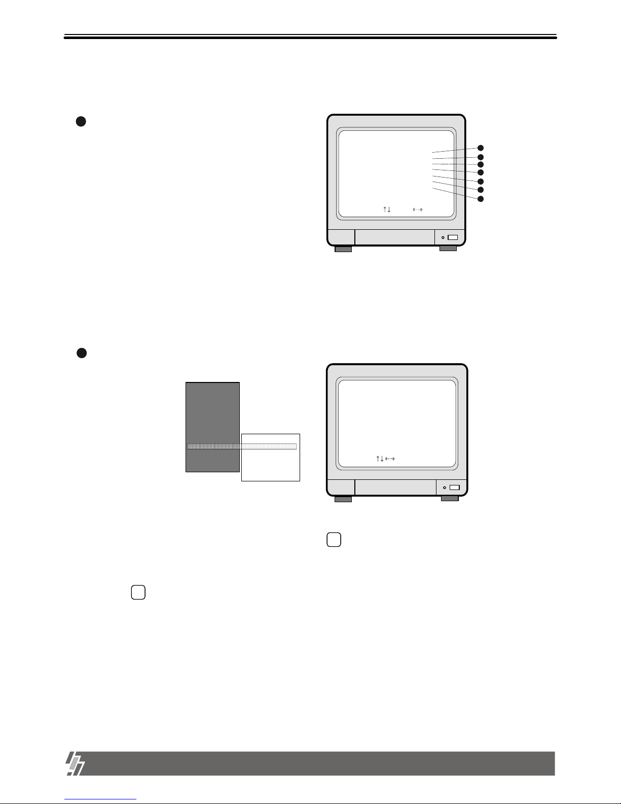
15-VP04-HDD2
&
15-VP04-CDRW
VER 5.53
04 Channel Video Processor
Safety & Security
Page 2

1
Table of Contents
Chapter 1 . Product package
Chapter 2. Installation procedure
1-1. The contents of package
3
1-2. Name and function of each button (front panel)
4
1-3. Name and function of each button (Rear panel)
5
2-1. Camera connection
6
2-2. Monitor connection (Composite monitor)
6
2-3. Monitor connection (S-VHS)
6
2-4. Sensor connection
7
2-5. Network connection
7
2-6. HDD connection
8
2-7. Power connection
8
Chapter 3. Operation
3-1. Basic Display
9
3-2. Playback
12
14
3-3. SYSTEM Log-in
15
3-4. System Set-up
15
16
17
18
19
22
22
23
Chap 4. Specification and Configuration
4-1. Specifications 25
4-2. Configuration 26
3-1-1. MODE
3-1-2. FRZ
3-1-3. SEQ
3-1-4. ZOOM
3-1-5. PIP
3-1-6. P/T
9
9
10
10
11
11
3-4-1. BASIC OPERATION
3-4-3. CAMERA SETUP
3-4-5. ALARM / MOTION SETUP
3-4-4. TIME/DATE Setup
3-4-6. RECORD SETUP
3-4-8. MISCELLANEOUS SETUP
3-4-7. TCP/IP SETUP
3-4-2. DISPLAY SETUP
Page 3

2
1. This document is intended for both the administrator and users of Video Processor model.
2. This manual contains information for configuring, managing and using Vid eo Processor model.
4. To prevent fire or electrical shock, do not expose the product to heat or moisture.
3. Be sure to read through this manual before using this Video Processor model.
5. Check electricity at the place you want to install the unit if it is stable and meets our electricity requirements. Unstable
electricity will cause malfunction of the unit or give critical damage to the unit.
6. Several chips on the main board of the unit and hard disk drive inside the unit generate heat, and it must be
properly discharged.
Do not put any objects just beside exhaust port(fan) on the left side of the unit and do not close up an opening
(fresh air in-take) on the right side of the unit.
7. Put the unit at well-ventilated place and do not put heat-generating objects on the unit.
When it is installed inside 19 inch mounting rack together with other devices, please check built- in ventilation fan of
the rack is properly running.
Before installing Video Processor, be sure to thoroughly review and follow the instructions in this User’s Manual.
Pay particular attention to the parts those are marked NOTICE.
Also, when connecting with external application, first turn the power OFF and follow manual instruction for appropriate installation.
8. For questions and technical assistance of this product, contact your local dealer.
About this manual
Before reading this manual
Install hard disk drive
1) HDD should be up to 7200rpm. Capacity of HDD is Max. 300GB. (Tested with maxtor HDD)
We recommend Maxtor HDD.
2) Please make sure that jumper setting of HDD must be MASTER.
3) After install HDD, start . First, set the date and time.
Set at Factory Default
in SETUP Menu and please clear HDD.
4) Go into Menu HDD Management HDD information and Verify that the second drive detected CD-Recorder.
15-VP04-HDD2 & 15-VP04-CDRW
Page 4
3
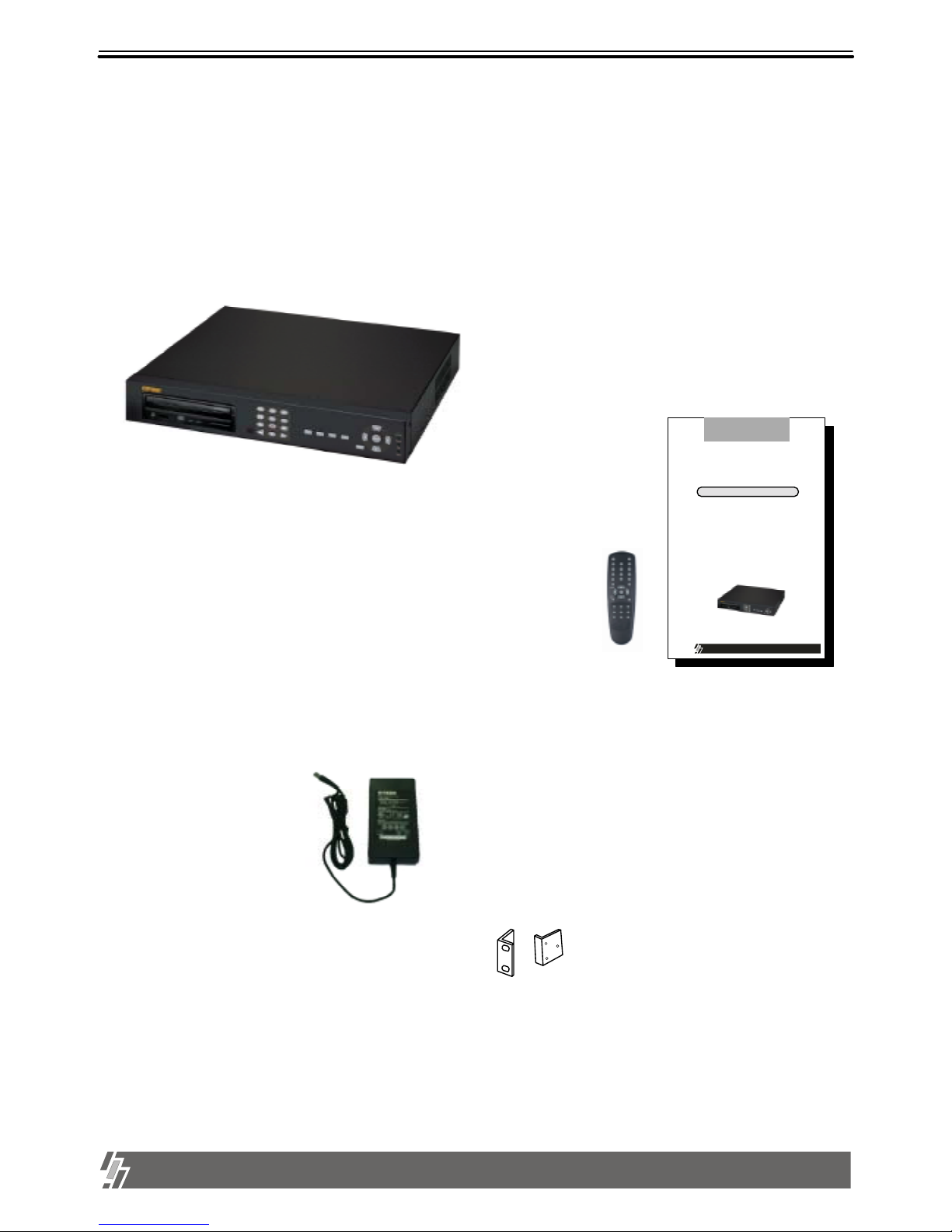
Chapter 1 . Product Package
1. Product package
15-VP04-HDD2 & 15-VP04-CDRW
1-1. The contents of package
1. 4 ch stand-alone unit
5. Accessories (Rack mount brackets, tapes and bolts )
Mounting bracket and bolts necessary for fixing unit into 19 inch rack, and batteries for remote controller.
4. DC power adapter and power cable
Converts AC 110V or AC 220V into DC 12V to supply unit.
3. Remote controller
IR remote controller enables full operation unit.
2. User manual
15-VP04-HDD2
&
15-VP04-CDRW
The most stable and relia ble real stand-alone Digita l Video Recorder
User Manual
VER 2.0
Safety & Security
04 Channel Digital Video Recorder
Page 5

ALL ABOUT IMAGE RECOGNITION & PROCESSING
4
1. Product package
15-VP04-HDD2 & 15-VP04-CDRW
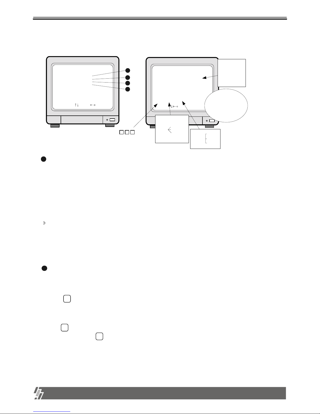
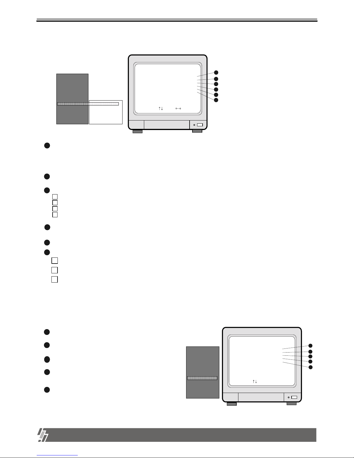
8. MODE : Changes to quarterly split screen or Full display screen.
4. MENU : Used to change menu in SYSTEM SETUP
2. ENTER : Used as selection key in SYSTEM SETUP mode or changes contents displayed in live display mode.
9. P/T : Enter into or exit from PAN/TILT CONTROL mode
5. Camera No : Represents camera numbers. Used with MODE button or to enter numbers.
10. PIP (MARK) : In full screen, this button assigns PIP( Picture In Picture ) .
7. FRZ : On-off switch to freeze pictures in live mode
6. SEQ : In full screen, this button shows pictures in rotation.
11. ZOOM : In full screen, this button enlarges pictures two times ( Possible to fix area to be enlarged using direction buttons.)
18. IR receiver : If blocked up by any object, remote controller does not work.
3. Direction key : Used to move in SETUP menu(Up/Down/Right/Left), or to change values
Notice : If several keys are pressed at the same time, or improper sequence in pressing buttons may cause
malfunction of unit.
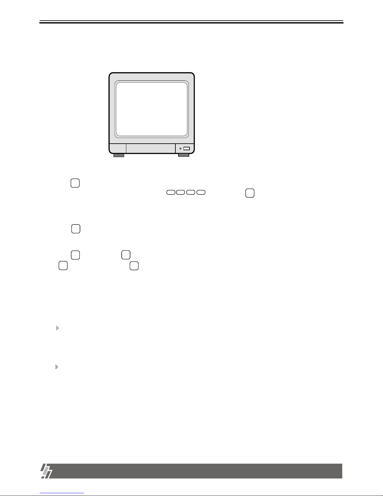
1. LED : Indicates the status of system (OVERWRITE / RECORD / PLAY / SETUP)
19. CD-RW or Mobile Rack : Back-up / Recording device
1-2. Name and function of buttons
[ Front Panel ]
13. Record ( ): Records picture data on hard disk drive
14. Stop ( ): Stops recording or playback
17. Fast backward ( ) : High speed playback in reverse direction in playback mode, or moving to the start of recorded data
when it is in stop mode
16. Playback ( ) : Start or exit playback.
15. Fast Forward ( ): High speed playback in forward direction in playback mode, or moving to the last of recorded
data when it is in stop mode.
12. Pause ( ): Pauses when it is in palyback mode
21
3
4
Enter
Menu
MODE
ZOOM
SEQ
P/T
FRZ
PIP
Se tu p
Play
Record
Overwr ite
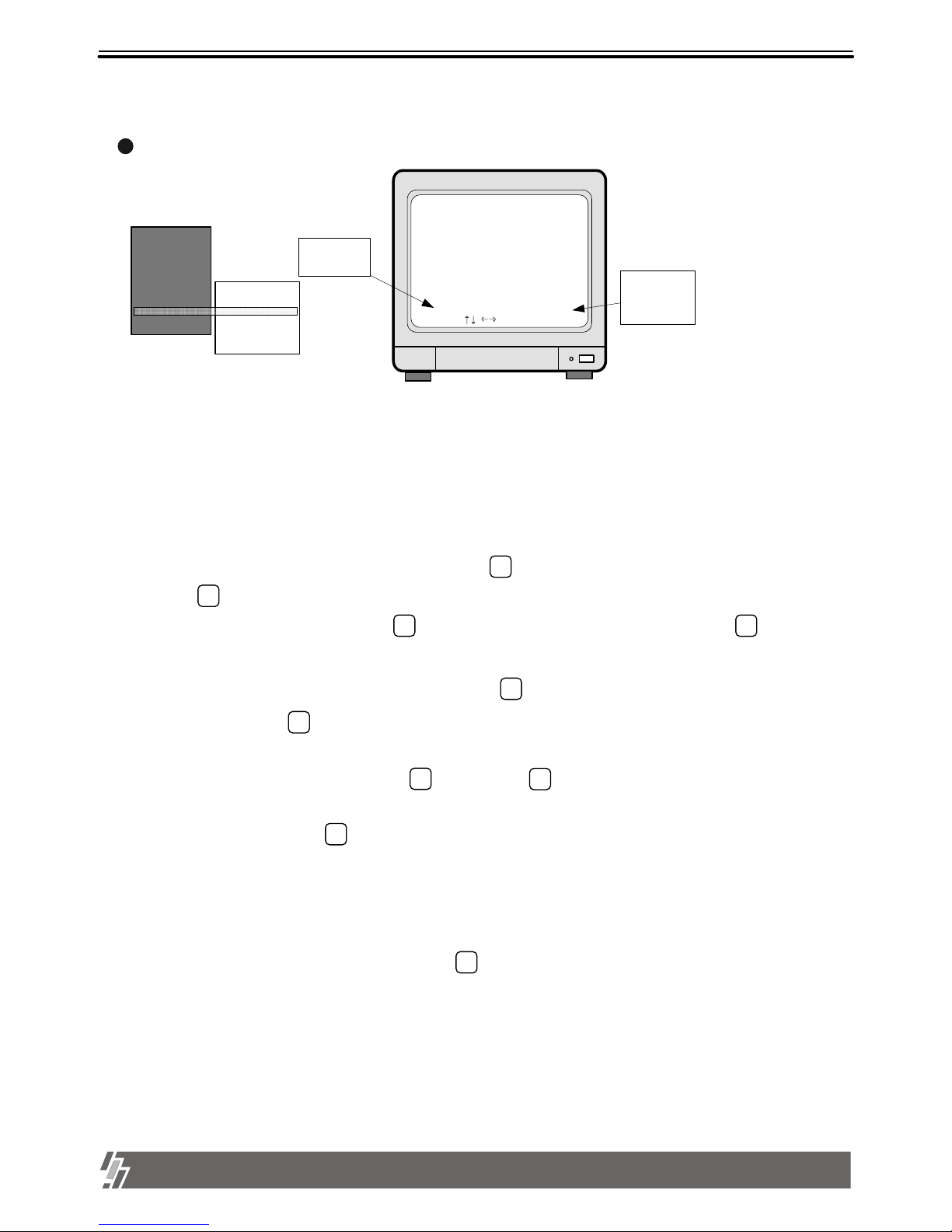
Page 6
5
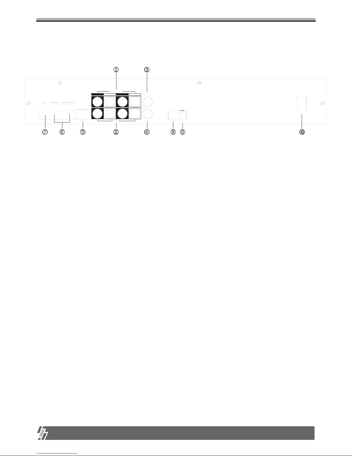
15-VP04-HDD2 & 15-VP04-CDRW
1. VIDEO INPUT : Connect cameras up to 4
2. VIDEO LOOP : Loop out from each camera from 1 to 4
NOTICE : When connecting with other applications, be sure to turn off the system.
3. MONITOR 1 : First Connect to co mposite monitor
4. MONITOR 2 : Additional Monitor output
8. S-VHS : Connect to S-VHS monitor for better quality of display
6. ALARM / RELAY : Connect to alarm input and relay output
7. RS-485 : Connect to external device of RS-485 protoc ol (PTZ camera control)
5. ETHERNET : Connect to Ethernet port for TCP/IP
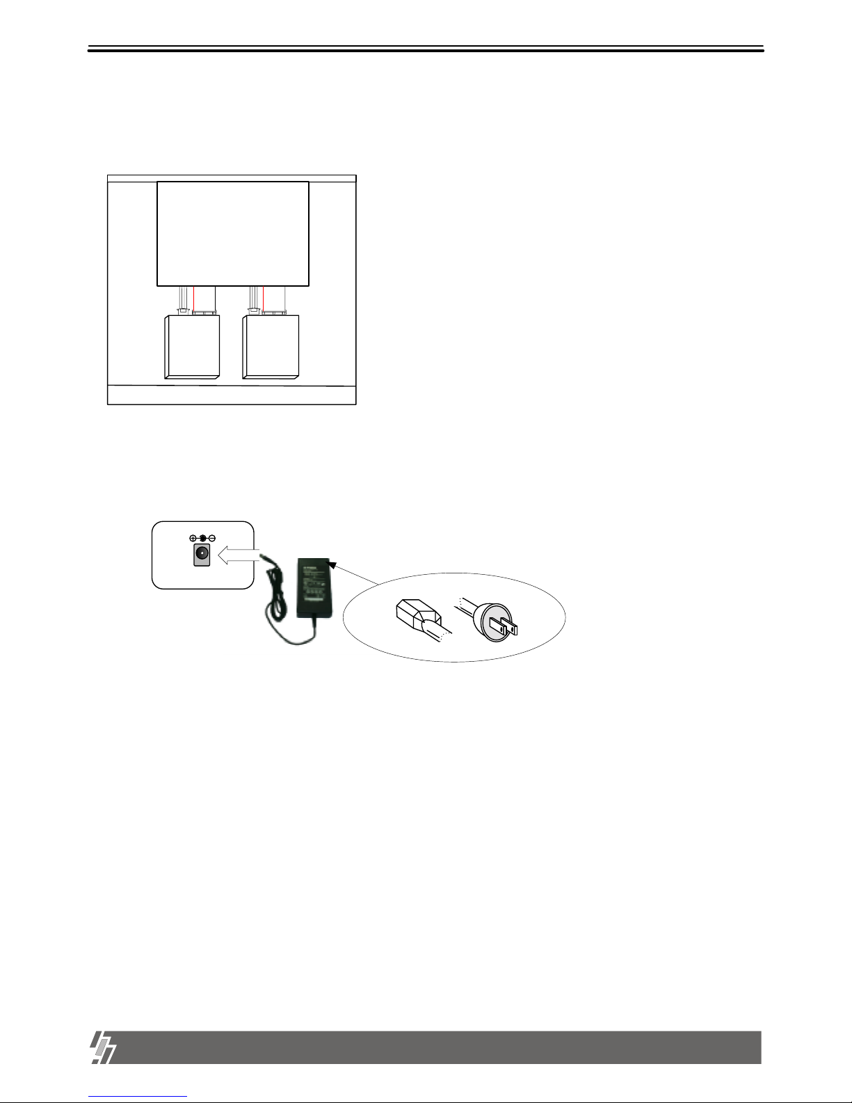
9. D/C 12V : Port for DC 12V, 5A.
10. POWER SWITCH WITH LED : DC Power Switch With LED
Generally speaking, cutting power to system may cause trouble in system or damage to HDD when
HDD is in writing process, and we ask you to press [MENU] button first to protect HDD from being
damaged or system failure before you press DC power switch off in practical operation.
[ Rear Panel ]
1-2. Name and function of each button
D
1
C
O
MD+
D
-
N
C
D2D4D
3
N
O
G
N
D
RELAYRS-485 ALARM
ETHERNET
LOOP
CH1
CH2
CH3
CH4
VIDEO INPUT
MONITOR 1
MONITOR 2
DC 12V
S-VHS
POWER
1. Product package
Page 7
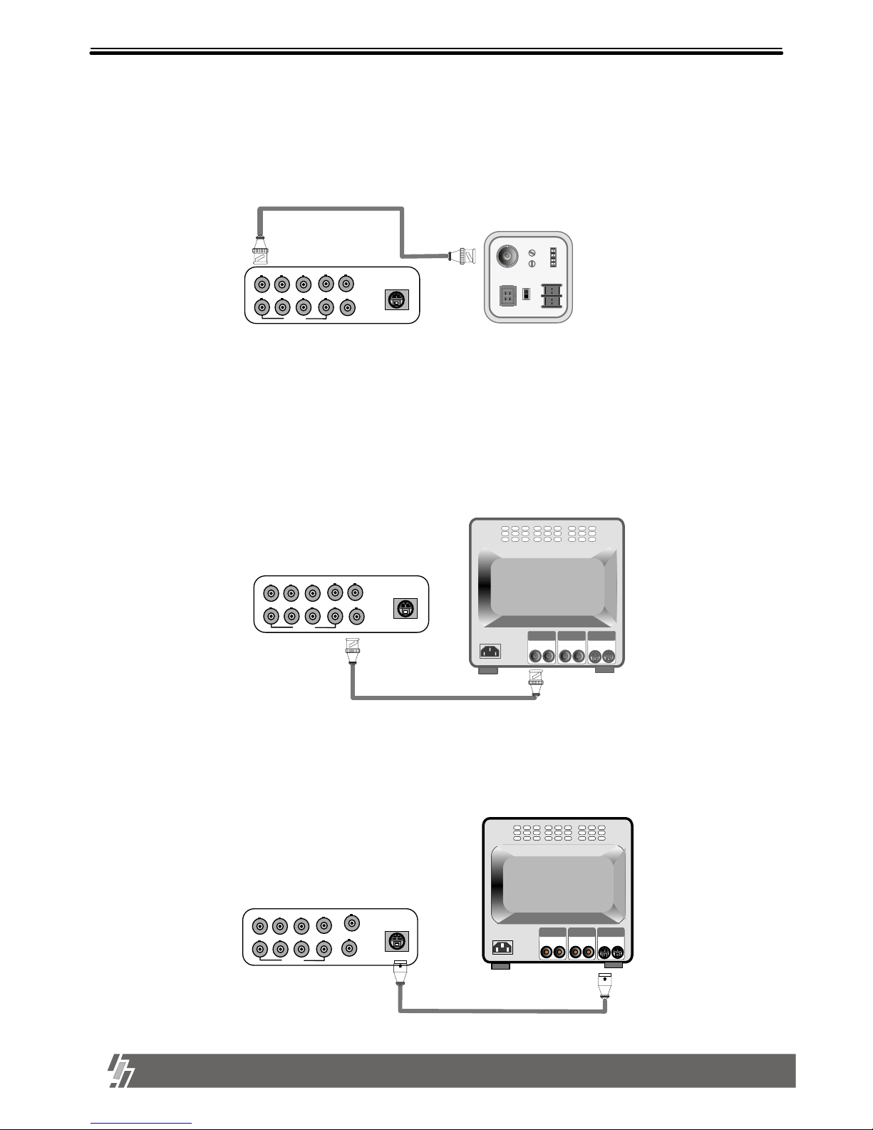
6
2. Installation
15-VP04-HDD2 & 15-VP04-CDRW
1) Camera Connection
Connect the camera to the CAMERA INPUT on the Rear Panel of the system.
2) Monitor Connection (Composite Connection Method)
Connect the monitor to the MONITOR OUT on the Rear Panel of the system
VIDEO
LENS
VIDEO
DC
AC24V/DC12
V.P
DC
LEVEL
Rear part of CAMERA
VIDEO A
IN OUT
VIDEO C
IN OUT
VIDEO B
IN OUT
CH1 CH2 CH3 CH4
LOOP
MONITOR 1
MONITOR 2
S-VHS
Notice : This system accepts camera with both PAL system or NTSC system automatically.
Connect camera and monitor while DC power switch on the front panel is off.
CH1 CH2 CH3 CH4
LOOP
MONITOR 1
MONITOR 2
S-VHS
CH1 CH2 CH3 CH4
LOOP
3) Monitor (S-VHS) Connection
Connect S-VIDEO Monitor to MONITOR OUT(S-VHS) on the Rear Panel of the system.
VIDEO
A
IN OUT
VIDEO
C
IN OUT
VIDEO
B
IN OUT
MONITOR 1
MONITOR 2
S-VHS
Chapter 2 . Installation Procedure
Page 8
7
2. Installation
15-VP04-HDD2 & 15-VP04-CDRW
ETHERNET
G
N
D
D
4
D3D
2
C
O
M
N
C
N
O
D
1
ALARM
RELAY
D
--
D
+
RS485
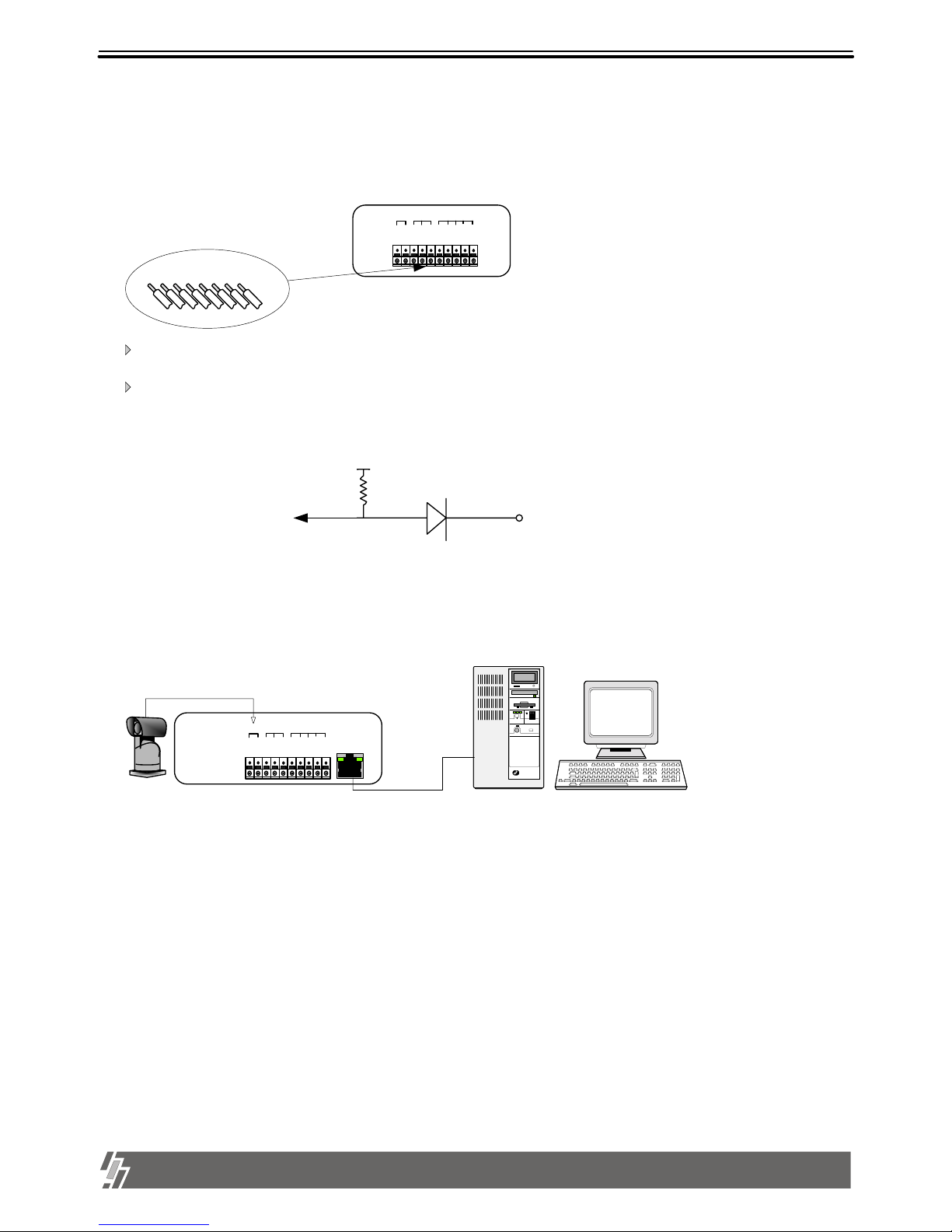
4) Sensor Connection
Connect the Sensor to the SENSOR INPUT/OUTPUT on the Rear Panel of the system
5) Network Connection
NOTICE : Sensor input is RECOGNIZED as LOW when alarm signal is on a level with GND,
and it is recognized as HIGH when alarm signal is FLOATING or 5V. Following is internal circuit.
Internal Circuit
D1
5
V
Thus, there is a danger of damage, when the sensor input goes to a Negative level or
voltage higher than 5V.
Terminal block
Pin 1 Alarm1
Pin 2 Alarm2
Pin 3 Alarm3
Pin 4 Alarm4
Pin 5 GND
Pin 6 NO( Normal Open )
Pin 7 NC( Normal Close)
Pin 8 COM
Relay output : COM+NC, COM+NO OR COM+NC+NO
Alarm input : Short-circuit between Alarm1, Alarm2, Alarm3 or Alarm4 and GND is recognized as alarm.
RS 485 : Connect to PTZ camera
RJ-45 (ETHERNET) : Connect to LAN, WAN or Internet
PTZ
CAMERA
G
N
D
D
4
D3D
2
C
O
M
N
C
N
O
D
1
ALARM
RELAY
D
--
D
+
COM NC NO GND D4 D3 D2 D1
RS-485
Page 9
8
15-VP04-HDD2 & 15-VP04-CDRW
7) Power Connection
Connect the power to the POWER CONNECTION on the Rear Panel of the system, and turn on the switch.
DC 12V
6) HDD connection
MAIN BOARD
HDD
Mobile
Rack
or
CD-RW
Connect main board and HDD using IDE HDD cable and power cable
included in the package.The jumper setting of HDD must be on Mater,
as specified by HDD manufacturer. The jumper setting must be done
properly as specified by HDD manufacturer. Fix HDD on the bottom of
case using screws included in the package. Screws must be inserted
from outside of the bottom.
And jumper setting of CD-RW DRIVE must be on Slave.
Mobile Rack must be on MASTER, the other HDD on Slave.
Notice : To turn off DC power switch on the Rear panel of case, be sure to press [MENU] button first.
If you press [MENU] button, system stops recording, and you can cut power to unit while HDD head is not in
writing mode. It is necessary to press [MENU] button first and turn DC power switch off to protect HDD head from being
damaged and eliminate possibility of mal-function of unit.
2. Installation
Page 10

9
15-VP04-HDD2 & 15-VP04-CDRW
3. Operation
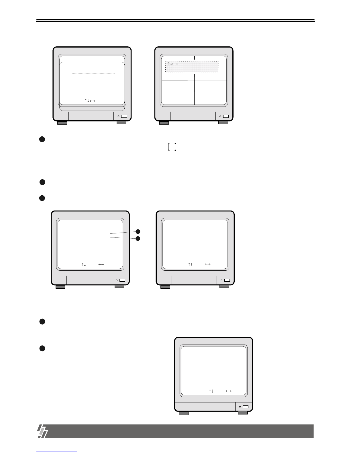
1. MODE
When button is pressed, the full screen
of each channel and quarterly split screen is played
MODE
With button, select
full screen of each camera.
1
2
3
4
2002 / APR / 01 PM 01:00:00
50FPS REC
CAM1 CAM2
CAM3 CAM4
Display of Recording Mode
by turns.
Indicates recording speed
50FPS : 50 Fields/sec
MOTION : records when motion
is detected
Indicates recording mode
REC : represents recording in
Field Switch Mode
Nothing displayed in Quad Mode
Indicates recording conditions
ALARM : records when alarm
condition is detected
Indicates
camera channel
1.
2. FRZ
1. Live full screen pauses when button is pressed.
2. To pause quarterly split screen,
FRZ
FRZ
1
2
3
4
press button, and with button
select channel. On the right of the camera name, “FRZ”
message appears and the LIVE screen of that channel
will pause. When pressed once more, it will come back to
NOTICE : When selected,
button or button do not work.
FRZ
1
2
3
4
MODE
To move to full screen of each camera, press button once more to end Freeze mode.
FRZ
LIVE screen.
CAM1
FRZ
CAM2
CAM3 CAM4
2002 / APR / 01 PM 01:00:00
60FPS REC FRZ
Indicates if “FRZ”
button selection.
When #1 camera is
paused in QUAD screen
Pause Screen
Chapter 3 . Operation
Basic Display
Page 11

10
3. Operation
15-VP04-HDD2 & 15-VP04-CDRW
3. SEQ
1.In LIVE full screen, press button to make picture from each channel rotate.
SEQ
CAM1
CAM2
CAM3 CAM4
2002 / APR / 01 PM 01:00:00
60FPS REC
Display of 4-split (Quad) screen
2. It does not operate in quarterly split screen.
3. During automatic rotation, press button to stop automatic rotation.
SEQ
MODE
2002 / APR / 01 PM 01:00:00
60FPS REC SEQ
Automatic rotation of the Full Screen
AB
CD
D
C
B
A
Full screen
automatically rotates
by the value of
SEQUENCE
INTERVAL in
A/B/C/D/A/B/C..
4.During automatic rotation, press button to stop automatic rotation and move to quarterly split screen.
PAGE.16. It is possible to select between 1 second to 99 seconds.
To change the time interval of the automatic rotation, change the value of SEQUENCE INTERVAL as per procedure
4. ZOOM
2004/NOV/15
REC
ZOOM in live view
L
R
T
B
PM03:36:08
ZOOM
1.In full screen in live mode or in playback mode, press [ZOOM] button to see 2 times enlarged picture.
2. Vertical bar and horizontal bar on the bottom and on the right respectively show which are of picture is enlarged, and you can change
area to be enlarged by pressing [LEFT], [RIGHT], [UP], and [DOWN] button.
3. Because it is enlarged 2 times digitally, picture quality is a little poor than picture you see in normal playback mode.
4. To exit ZOOM mode, just press [ZOOM] button again.
Page 12

11
3. Operation
15-VP04-HDD2 & 15-VP04-CDRW
6. P/T
1. Press button.
P/T
ENTER
P/T
3. Use [LEFT]/[RIGHT] button to select the command
2.Use [UP]/[DOWN] button to choose the ADDRESS
of the P/T camera.
4. With button, select ON/OFF.
5. Press button to come back to recording
for P/T camera you want to transmit.
2002 / APR / 01 PM 01:00:00
60FPS REC
CAM1 CAM2
CAM3 CAM4
P/T CH1 FOCUS FAR
EXIT : PRESS [P/T]
1. Indicates address of camera
0~255
2. Select
Command
FOCUS FAR
FOCUS NEAR
FOCUS AUTO
PAN RIGHT
PAN LEFT
TILT UP
TILT DOWN
ZOOM IN
ZOOM OUT
AUTO PAN
LIGHT CMD
WIPER CMD
PUMP CMD
POWER CMD
FUNTION 1
FUNTION 2
FUNTION3
3. Set ON/OFF
for selected
command
Display of PAN/TILT Control
screen
In most of cases, while you press button, it
is ON, and OFF while not pressed.
ENTER
5. PICTURE IN PICTURE (PIP)
1
2
3
4
PIP
SEQ
1. Use button to select a camera
and set a full screen.
2. Press button.
3. With [UP]/[DOWN] or button, select the
NOTICE : PIP is not available in quarterly split screen.
camera channel in full screen, and with [LEFT]/[RIGHT]
button select the channel of smaller screen.
4. Press button to make the image in smaller
screen rotate.
To change the location of smaller screen, press button and use direction button to move to desired
FRZ
location.
1
2
3
4
2002/APR/1 PM 09:22:06
60FPS REC PIP FL
PIP WINDOWS MOVE : OFF
MOVE ON/OFF : PRESS PRZ
CAM1
Indicates if “SEQ” button
selection.
Indicates “FRZ”
key selection.
Display of PICTURE IN PICTURE
7. NOTICE
1) Recording is stopped during SYSTEM SETUP.
2) Recording is stopped during playback, or search in playback mode.
3) Recording is not possible if no camera is connected.
Page 13

12
3. Operation
15-VP04-HDD2 & 15-VP04-CDRW
2) After pressing , press or and button and use [LEFT]/[RIGHT] button to advance single frame to the right
1. Playback setup
1) Press button to begin playback.
PLAY
2) Display screen as shown on the right will appear
3) Press button again to start playback from
START picture.
ENTER
2. GOTO time setting
1) At , use [LEFT]/[RIGHT] button to choose the date or time of GO TO.
2) Use [UP]/[DOWN] button, set desired time.
(To start from a specific time, first set the
GO TO time before press button.)
3) Press button to replay from the GO TO time.
NOTICE : During playback or setting GO TO time, recording is stopped
3. Pausing and single frame advanced
1) During playback, press button to pause. (Will replay when pressed once more)
SEQ
NOTICE : When value that is out of the range of start and end is entered, it starts from START time
4) To come back to recording mode.
press or button.
NOTICE : When value is in the range of START and END, but there is no recorded pictures at the set time,
it moves to the closest time of the recorded pictures.
START : 2002/APR/12 AM 07:40:38
END : 2002/APR/20 PM 02:11:56
GOTO : 2002/APR/15 AM 00:00:00
Time recording
started.
Time recording
ended.
Indicate time to be
played.
Display of Search(GOTO) mode
2
3
3
1
Playback
2.
or left.
ENTER
ENTER
Playback
Page 14

13
3. Operation
15-VP04-HDD2 & 15-VP04-CDRW
6. MARK IMAGE (Internal backup) SETUP
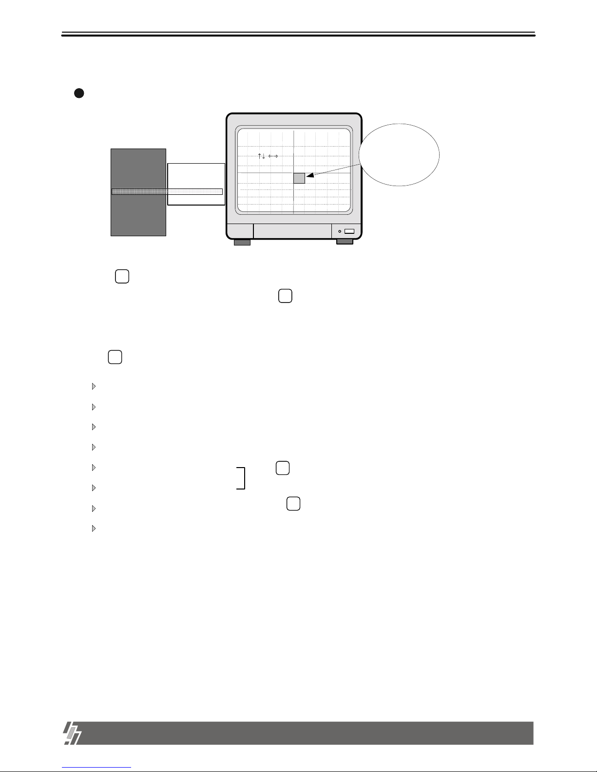
5. Display Enlargement.
2) Press button, during Playback or PAUSE mode.
ZOOM
3) The display will enlarge by 200%
4) Use direction button to move the area enlarged.
5) Press to go back to Playback or FRZ mode.
ZOOM
1) Choose camera by pressing button.
1
2
3
4
4. Playback Speed Setup
1) During playback , press or and button.
SEQ
2) Display screen will appear as on the right.
3) On SEQ mode, use [LEFT]/[RIGHT] button to move forward (FF) or
4) Use [UP]/[DOWN] button to select the speed rate.
(High speed up to x60 and slow speed up to 1field/60sec is possible.)
Refer to MISCELLANEOUS SETUP : MARK IMAGE SETUP in PAGE.28 for details.
During Playback, press button and choose pictures using [LEFT]/[RIGHT] button to protect selected
PIP
2002/APR/12 AM 07:40:38
1X PLAY SPEED
CAM1 CAM2
CAM3 CAM4
We recommend you to install 7200rpm EIDE hard disk drive.
5400rpm EIDE hard disk drive is not good enough to retrieve recorded data
in high speed and slow speed playback mode.
ZOOM
Press(X2 Enlargement)
Press
Chosen
1X PLAY SPEED
2X PLAY SPEED
4X PLAY SPEED
8X PLAY SPEED
16X PLAY SPEED
32X PLAY SPEED
60X PLAY SPEED
Chosen
1X PLAY SPEED
1/2 PLAYSPEED
1/4 PLAYSPEED
1/8 PLAYSPEED
1/16 PLAYSPEED
1/32 PLAYSPEED
1/60 PLAYSPEED
Playback speed
Display of PLAYBACK SPEED SETUP
backward (REW).
pictures from being overwritten when hard disk is full
During playback at 60x speed, blue screen comes into view instantaneously
once in a while and you could not see some pictures at that moment even
though all they were recorded correctly, due to limitation in speed of reading
data on a hard drive, and it is not a critical error in operation of unit.
To see pictures you could not see, just go back for some seconds and
replay at a little lower speed than before.
Page 15

14
3. Operation
15-VP04-HDD2 & 15-VP04-CDRW
NOTICE : We recommend you to enter your own password as per procedure in page.23 to change the password.
5) After entering the password, press button to go back to the system menu.
MENU
If password entered matches previously set number, “ADMIN GRADE LOGIN OK” message appears.
If password entered does not match previously set number “CURENT PW INPUT ERROR” message
appears.
LOGIN SYSTEM
PASSWORD ( )
1,2,3,4 : INPUT PASSWOR
PIP(MARK) : ERASE PASSWORD
MENU : ENTER OR EXIT
Enter the password
default P/W : 1
NOTICE : Be sure to memorize the changed password.
Display of Login SYSTEM
Log-in
Log-in
3.
NOTICE : To protect hard drive from damaged, turn off the power switch of unit after you first press [MENU] button.
If you press [MENU] button, unit stops recording, and HDD head is not in the process of writing.
Factory default password is 1.
Page 16
15
3. Operation
15-VP04-HDD2 & 15-VP04-CDRW
1. Basic Operation
1) Press button.
MENU
2) Use [UP]/[DOWN] button to select setup item.
3) Press button to enter sub-menu of selected SETUP.
4) Press sub-menu item with [UP]/[DOWN] button, and change the value with [LEFT]/[RIGHT] button.
5) Press button to forward button to go backward.
MENU
6) To go back to the very first SETUP condition recommended by manufacturer, set at FACTORY DEFAULT.
SYSTEM SETUP
DISPLAY SETUP
TCP/IP SETUP
RECORD SETUP
ALARM/MOTION SETUP
CAMERA TITLE
TIME/DATE SETUP
MISCELLANEOUS
FACTORY DEFAULT
SELECT UP/DOWN , ENTER
Display of SYSTEM SETUP
2) Log into the system by entering the password with button and press button
Items remain unchanged when FACTORY DEFAULT is selected.
1. value of TIME/DATE SETUP 2. Date stored on HDD
3. Marked image (Internal backup) 4. ADMIN password
5. ALARM LIST SETUP
1
2
3
4
MENU
to enter SETUP MENU.
button enables to enter and button to go back.
MENU
We recommend users to set at FACTORY DEFAULT in the first operation, or after you replaced HDD.
System Setup
System Setup
4.
You can set at FACTORY DEFAULT all in one (as a whole) or group by group. When cursor is at ALL SETUP, you can set at ON
or OFF by pressing [ENTER] button. If you set ALL SETUP at ON, all groups of settings are SET as per FACTORY DEFAULT
recommended by manufacturer. If you set ALL SETUP at OFF, then you are requested to set each group of settings separately
one by one, ON or OFF, and groups of settings set at ON shall be reset whenever you set at FACTORY DEFAULT.
To reset, you have to select ALL SET or each group of settings (ON or OFF), and then move to RESET NOW and press [ENTER].
ENTER
ENTER
ENTER
Page 17
16
3. Operation
15-VP04-HDD2 & 15-VP04-CDRW
2. DISPLAY SETUP
PB TIME/DATE : On Playback screen, Date and Time is indicated.
DISPLAY SETUP
TIME/DATE
CAMERA TITLE
PB TIME/DATE
PB CAMERA TITLE
DVR STATUS
BORDER SET
SEQUENCE INTERVAL
DISPLAY TYPE
SELECT , PRESS
: ON
: ON
: ON
: ON
: ON
: WHITE
: 01
: COMPO
1
2
3
4
5
6
7
This is about the contents displayed on the display screen.
2002/ARP12 AM 07:40:38
60FPS REC
CAM1 CAM2
CAM3 CAM4
1
2
TIME/DATE : Date and time is indicated on LIVE screen.
CAMERA TITLE : Camera TITLE is indicated on LIVE screen.
PB CAMERA TITLE : Camera TITLE is indicated on the Replay SCREEN.
DVR STATUS : indicates status of operation, such as REC/REPLAY.
BORDER SET : Changes the color of the border - WHITE/ BLACK
SEQUENCE INTERVAL : Sets rotating time interval of pictures . In full screen in live mode or playback mode, pictures are rotating in a
certain time interval, when you press button, and SEQUENCE INTERVAL is for it.
( Time interval from 1 second to 99 seconds)
7
6
5
4
3
A
B
C
D
E
F
Display of DISPLAY SETUP
A C
E
B
D
F
SEQ
8
Page 18

17
3. Operation
15-VP04-HDD2 & 15-VP04-CDRW
3. CAMERA SETUP
1
2
COLOR SETUP : Adjust Camera Image
TITLE SETUP : Input TITLE of each camera
CH NUMBER
BRIGHTNESS
CONTRAST
SATURATION
HUE
GAIN
(-31~ +32)
(-31~ +32)
(-20~ +32)
(-31~ +32)
(-31~ +32)
: Select camera
: Adjust screen brightness
: Adjust color contrast
: Adjust color saturation
: Adjust color hue
: Adjust image signal level
1) Use [LEFT]/[RIGHT] button to select CHANNEL and press button
2) Go into CHANNEL content and use [LEFT]/[RIGHT] button to move to item to be
changed and use [UP]/[DOWN] button to change the letters.
MENU
CAMERA SETUP
COLOR SETUP
TITLE SETUP
ACTIVE CH SETUP
SCREEN POSITION SETUP
COLOR BAR TEST
SELECT , PRESS
1
2
3
4
Display of Camera Setup
5
CAMERA COLOR SETUP
CH NUMBER
BRIGHTNESS
CONTRAST
SATURATION
HUE
GAIN
SELECT , PRESS
Display of CAMERA COLOR SETUP
1
+2
-2
-8
+0
+0
When modification is finished, press button to come back to the MAIN MENU.
Display of CAMERA TITLE SETUP
CAMERA TITLE SETUP
SELECT , PRESS ENTER
0 1 2 3 4 5 6 7 8 9 . , < > ( ) - = A B C D
E F G H I J K L M N O P Q R S T U V W X Y Z a b
c d e f g h I j k l m n o p q r s t u v w x y z
CH1
CH2
CH3
CH4
(CAM 1 )
(CAM 2 )
(CAM 3 )
(CAM 4 )
Right adjustment of each element in COLOR setup will increase picture quarterly displayed.
We recommend you to adjust each element of COLOR SETUP for cameras and monitor to be connected
to the unit, for better appearance.
▶
▲
ENTER
3. CAMERA SETUP
Page 19
18
3. Operation
15-VP04-HDD2 & 15-VP04-CDRW
1
2
SET TIME/DATE : Can set year/month/time/minute/second.
SET the notation of TIME/DATE :
Use [UP]/[DOWN] button to assign Year/Month/Time/Minute/Second and use [LEFT]/[RIGHT] button to change the value.
1. HOUR DISPLAY :
2. DATE DISPLAY :
3. MONTH DISPLAY :
SET TIME/DATE
YEAR
MONTH
DAY
HOUR
MINUTE
SECOND
SELECT , PRESS
2002/APR/15
PM 09:23:17
TIME/DATE SETUP
SET TIME/DATE
SET TIME/DATE TYPE
SELECT , PRESS
1
2
Changes to AM/PM or 24hour time indication
Converts into Asian type/American type/European type
Month indication is changed to English or Numeric
TIME/DATE TYPE SETUP
HOUR DISPLAY
DATE DISPLAY
MONTH DISPLAY
SELECT , PRESS
: AM/PM
: ASIAN
: ENGLISH
Display of Time/Date TYPE
Display of TIME/DATE SETUP
ACTIVE CH SETUP :
COLOR BAR TEST : COLOR BAR CHART is generated.
5
3
Used for adjusting the monitor
CAMERA ACTIVE SETUP
CHs
CH1
CH2
CH3
CH4
SELECT , PRESS ENTER
Display of CAMERA ACTIVE Setup
LIVE
ON
ON
ON
ON
STATUS
ACTIVE
ACTIVE
ACTIVE
ACTIVE
REC
ON
ON
ON
ON
: SCREEN POSITION
ADJUSTMENT
ENTER : DEFAULT POSITION
CAM1 CAM2
CAM3 CAM4
Display of Screen Position Adjustment
2. LIVE : Decides whether to show LIVE screen image or not.
With direction button, move to item to be changed, and press button to select ON/OFF.
1. STATUS : In normal cable condition it is indicated as ACTIVE, and when the cable is disconnected or has problem, it is indicated as LOSS.
3. REC : Decides whether to record relevant channel or not.
SCREEN POSITION SETUP
4
Use direction button to move the full screen according to the user’s needs.
ENTER
4. TIME/DATE SETUP
Page 20
19
3. Operation
15-VP04-HDD2 & 15-VP04-CDRW
5. ALARM/MOTION SETUP
1
ALARM SETUP : Sets type of alarm sensors connected to unit.
OFF : No alarm sensor is connected.
NC : Normal Closed alarm sensor. When an event happens, Contact is opened.
NO : Normal Open alarm sensor. When an event happens, Contact is closed.
ALARM DURATION : Duration of recording, when an ALARM is activated.
ALARM/MOTION SETUP
ALARM SETUP
ALARM LIST SETUP
MOTION SETUP
MOTION MASK SETUP
SELECT , PRESS
1
2
3
4
2
ALARM LIST SETUP : Shows list of alarms up to 400. If total alarm exceeds 400, it overwrites from the beginning.
Alarm list is very helpful to manage system.
1. With [LEFT]/[RIGHT] button, select SORT, DELETE or GO TO.
ALARM LIST SETUP
NO DATE TIME TYPE
CALM
………………………………………………………
001 02/04/01 21 : 14 : 11 3_H_
. . . .
. . . .
. . . .
. . . .
. . . .
SORT : TIME DELETE GOTO
SELECT , ENTER OR MODE
Move to play screen of relate
appropriate time.
1 2 3
Sort
method
CH
SORT TIME
TYPE
DELETE MARK
PAGE
ALL
2. SORT
Press button to select submenu of SORT ,that are CH ,TIME and TYPE.
1) CH : Sort by CHANNEL 2) TIME : Sort by TIME 3) TYPE : Sort by TYPE
3. DELETE
Press button when DELETE is highlighted, and select MARK, PAGE or ALL using [LEFT]/
[RIGHT] button and press button.
1) MARK : Deletes marked item in the list.
C: CAMERA
A : ALARM
L : LOSS
M :MOTION
ALARM POP-UP : When an alarm is activated, display screen is switch to full screen of image from relevant
channel, and a color of camera number is changed to red.
If an alarm is activated from 2 channels, display screen is changed to quarterly split screen
(Quad screen), and a color of camera number of relevant channel is change to red.
Display of ALARM/MOTION SETUP
SELECT LIST TYPE : Select type of event to be enlisted in the event list. “A” indicates Alarm, “L” indicates Loss,
and “M” indicates Motion. You can select NONE if you do not want to have event list, an d
ALM if you want all of Alarm, Loss and Motion are enlisted in event list, by pressing
[LEFT] and [RIGHT] button.
ENTER
ENTER
ENTER
Page 21
20
3. Operation
15-VP04-HDD2 & 15-VP04-CDRW
3
MOTION SETUP :
CHANNEL NUM : Selected camera number
SENSITIVITY : Adjusts motion Detection Sensitivity. (Not Sensitive Sensitive)
DETECT WINDOW NUM : Detects moving objects bigger than DETECT WINDOW NUM.
Can choose from 1 to 20. If DETECT WINDOW NUM value is 5, motion detections
is activated only in case 5 cells are simultaneously detected.
AUTO FREEZE TIME : When MOTION is detected, the screen freezes for set time automatically.
Not to use this functionality, set at OFF.
Setup Time : 1,2,3,5,10 SEC
3) ALL : Deletes ALL.
4. GOTO : Starts playback from the marked item in the list.
2) PAGE : Deletes current PAGE.
Move to alarm number in the list using [UP]/[DOWN] button, and press button to mark
“*”.
MODE
Move to an item in the list using [UP]/[DOWN] button, and press button to mark.
MODE
SYSTEM SETUP
DISPLAY SETUP
CAMERA TITLE
TIME/DATE SETUP
ALARM/MOTION SETUP
RECORD SETUP
TCP/IP SETUP
MISCELLANEOUS
FACTORY DEFAULT
ALARM SETUP
ALARM LIST SETUP
MOTION SETUP
MOTION MASK SETUP
MOTION SETUP
CHANNEL NUM : 1
SENSITIVITY GRADE
LOW [------------------------ ] HIGH
DETECT WINDOW NUM : 01
AUTO FREEZE TIME : OFF
SELECT , PRESS
Adjust to Left/Right
When motion detected,
pause screen for set time
Camera selected
MOTION REC DURATION : 1 SEC
MOTION REC DURATION : Sets duration of recording when a motion is detected.
Set value from 1 sec to 3 minutes according to frequency of motion,
and FACTORY DEFAULT value is 5 sec.
Size of object in motion.
If you set the Detect Window
Number at high like 10 or 15,
motion of small objects are
not deteted.
Page 22
21
3. Operation
15-VP04-HDD2 & 15-VP04-CDRW
MOTION MASK SETUP : Set detection area.
4
SELECT VER LINE : Select all in a vertical line.
CLEAR VER LINE : Clear all in a vertical line.
SELECT HOR LINE : Select all in a horizontal line.
CLEAR HOR LINE : Clear all in a horizontal line.
SELECT BLOCK : Select by BLOCK.
CLEAR BLOCK : Clear the BLOCK.
SELECT ALL CELLS : Select all.
CLEAR ALL CELLS : Clear all.
1. Press button to choose desired EDIT mode.
2. Use [LEFT]/[RIGHT] button to assign BLOCK, and press button to set.
3. MASK area in green color is detection area, and the rest is no detection area.
P/T
5. With button, select channel (1,2,3,4,quad) to set for each camera.
MODE
4. Detected area is indicated in Green, and not detected area is indicated as colorless.
Setup is possible only on the Full screen.
When button is pressed, [START] is displayed.
Then select blocks using direction button.
EDIT MODE : SELECT EACH CELL
P/T : CHANGE EDIT MODE
MODE : CHANGE CHANNEL
ENTER : MASK ON/OFF
: CURSOR MOVE
With the direction butt on,
choose MASK area.
SYSTEM SETUP
DISPLAY SETUP
CAMERA TITLE
TIME/DATE SETUP
ALARM/MOTION SETUP
RECORD SETUP
TCP/IP SETUP
MISCELLANEOUS
FACTORY DEFAULT
ALARM SETUP
ALARM LIST SETUP
MOTION SETUP
MOTION MASK SETUP
And press button to set.
Display of MOTION MASK SETUP
ENTER
ENTER
ENTER
Page 23
22
3. Operation
15-VP04-HDD2 & 15-VP04-CDRW
6. RECORD SETUP
RECORD SETUP
HDD CLEAR
HDD FULL
RECORD MODE
RECORD TYPE
RECORD SPEED
PRIORITY MODE
SELECT , PRESS
: NO
: OVERWRITE
: TIMER
: FIELD
: 60FPS
: NONE
1
2
3
4
5
6
1
2
HDD CLEAR : If YES is selected, it deletes content of the HDD.
RECORD MODE
3
1
TIMER : Records by time.
TIMER+ALARM : Records by time or when the ALARM comes in. (POST-ALARM Functionality)
2
MOTION+ALARM : Records by MOTION or when the ALARM comes in.
MOTION : Records only when MOTION is detected.
4
3
RECORD TYPE
RECORD SPEED : Adjusts recording frame rate : 0.1 indicates 1 field per 10 seconds. (60/30/15/10/5/2/1/0.5/0.2/0.1 FPS)
PRIORITY MODE : Assigns recording priority of a specific channel.
6
5
4
FIELD : Records images from each camera in rotation. 60 fields/sec at 720X240 resolution.
NONE : Each of 1,2,3,4 does not have priority.
1 : Gives priority to #1 camera, and records in the sequence of 1-2-1-3-1-4-1-2….
1
2
3 1,2 : Gives priority to #1 and #2 cameras, and records in the sequence of 1-2-3-1-2-4-1-2-3.
HDD FULL : Select OVERWRITE or STOP RECORD. If OVERWRITE is selected, it delete previous contents on HDD to overwrite
when HDD is full.
SYSTEM SETUP
DISPLAY SETUP
CAMERA TITLE
TIME/DATE SETUP
ALARM/MOTION
SETUP
RECORD SETUP
TCP/IP SETUP
MISCELLANEOUS
FACTORY DEFAULT
HDD CLEAR
HDD FULL
RECORD MODE
RECORD TYPE
RECORD SPEED
PRIORITY MODE
Notice : All contents of the HDD is deleted and cannot be restored.
As times go by, HDDs in a unit will have bad sectors one after the other.
Pictures to be recorded in bad sectors shall be damaged, and you will see incomplete pictures whenever you replay.
However, our unit operates normally even though there is some bad sectors in hard disk drives.
Display of RECORD SETUP
7. TCP/IP SETUP
TCP/IP SETUP
IP ADDRESS
GATEWAY
SUBNET MASK
MAC ADDRESS
DHCP SETUP
SELECT , PRESS ENTER
1
2
3
4
4
3
MAC ADDRESS : It is unique ID number provided by the
manufacturer, and the user should not change under any
condition.
TCP/IP option of this system enables user to see live pictures and recorded pictures via internet line, far apart from unit. To see live pictures
or recorded pictures of , users must input IP address, Gateway, and Subnet mask in TCP/IP SETUP in first, and then input IP, PORT number
and PASSWOR(ADMIN password in unit) in Remote Viewer Program installed on client PC.
For detail procedure for installing Remote Viewer Program and setting up, refer to manual for Remote Viewer program included in the package.
SUBNET MASK : Enter numbers using direction buttons and
press [MENU] button.
SYSTEM SETUP
DISPLAY SETUP
CAMERA TITLE
TIME/DATE SETUP
ALARM/MOTION SETUP
RECORD SETUP
TCP/IP SETUP
MISCELLANEOUS
FACTORY DEFAULT
5
DHCP SETUP : In case you connect unit to LAN network
under router/Gateway/IP sharer which has DHCP serve r function,
set DHCP SETUP at DHCP, and unit automatically gets IP
data automatically during the process of booting. In case you connect
unit to leased line with static IP or Router/Gateway connected
(A)DSL line (with static IP or dynamic IP), you are requested to set DHCP at MANUAL and input IP data manually. For details,
refer to Remote Viewer manual.
5
TCP/IP SETUP
IP ADDRESS : Enter numbers using direction buttons and press
[MENU] button.
GATEWAY : Enter numbers using direction buttons and press
[MENU] button.
1
2
Page 24
23
3. Operation
15-VP04-HDD2 & 15-VP04-CDRW
8. MISCELLANEOUS SETUP
1
2
BUZZER SETUP : Sets different kinds of BUZZER ON/OFF.
ID/PW SETUP : Sets User ID and PASSWORD.
Notice : In the very first setup stage, the ADMIN PASSWORD is “1”, and USER PASSWORD is “2”.
Change PASSWORD as soon as this product is purchased.
1) With [UP]/[DOWN] button, select item to be changed, and press button to edit.
2) With [LEFT]/[RIGHT] button, move to wanted location and use [UP]/[DOWN] button to
make Selection.
4) After entering current password, enter new password and enter new password on ce more to verify.
3) Press button after every SETUP and to be ready for next SETUP item.
MISCELLANEOUS SETUP
BUZZER SETUP
ID/PW SETUP
SCHEDULE REC SETUP
PANTILT CMD SETUP
HDD INFORMATION
MARK IMAGE SETUP
PRODUCT ID
SELECT , PRESS
1
2
3
4
5
SYSTEM SETUP
DISPLAY SETUP
CAMERA TITLE
TIME/DATE SETUP
ALARM/MOTION SETUP
RECORD SETUP
TCP/IP SETUP
MISCELLANEOUS
FACTORY DEFAULT
BUZZER SETUP
ID/PW SETUP
SCHEDULE REC SETUP
PANTILT CMD SETUP
HDD INFORMATION
MARK IMAGE SETUP
PRODUCT ID
6
7
ID/PW SETUP
SELECT , PRESS ENTER
ID
CURRENT
NEW
CONFIRM
< USER >
< >
< >
< >
PW
PW
PW
1,2,3,4 : INPUT PASSWORD
MARK : ERASE PASSWORD
Display of MISCELLANEOUS SETUP
Display of ID/PW SETUP
BUZZER SETUP is available for each group as follows.
SYSTEM BUZZER
BUTTON BUZZER
ALARM BUZZER
MOTION BUZZER
LOSS BUZZER
You can set each group of BUZZER independently and
BUZZER is activated just in case you set at ON in
corresponding group of BUZZER SETUP.
ENTER
ENTER
Page 25
24
3. Operation
15-VP04-HDD2 & 15-VP04-CDRW
SCHEDULE REC SETUP :
3
Records according to schedule by day or a day of the week. Two recording time spans can be set for a day and a day of the
week respectively. In total, 4 recording time spans can be set in a day.
system records just as you set if you set SCHEDULE REC SETUP, and system records 24 hours a day if you do not set
SCHEDULE REC SETUP.
1. Scheduled Recording for a day:
button is pressed.
3) Set recording time for START and END with button. Recording time increases by 30 minutes whenever
4) After set START and END time for a day and set ON/OFF using button.
MODE
5) After set all data, press button once more to memorize settings you set in the system.
6) RESET is used to delete previously set recording schedule.
(NONE : Does not reset DATE : deletes only selected date ALL : deletes all)
MENU
2. Scheduled recording by a day of the week :
WEEK in MODE of SCHEDULE REC SETUP by pressing button.
7) When all input is ended, press button to come back to SCHEDULE REC SETUP.
Set recording time for each day of the week as the procedure for Scheduled Recording for a day.
MODE
Select DATE, and move to the date by pressing button, and press to delete. ALL deletes all recording schedule.
MODE
SCHEDULE REC SETUP
NONE : No reset
DATE : Reset selcted
date only
All : Reset all.
DATE : Set by day
WEEK : Set by a day
of the week
Display of SCHEDULE REC SETUP
SYSTEM SETUP
DISPLAY SETUP
CAMERA TITLE
TIME/DATE SETUP
ALARM/MOTION
SETUP
RECORD SETUP
TCP/IP SETUP
MISCELLANEOUS
FACTORY DEFAULT
BUZZER SETUP
ID/PW SETUP
SCHEDULE REC SETUP
PANTILT CMD SETUP
HDD INFORMATION
MARK IMAGE SETUP
PRODUCT ID
YY-MM-DD
02-07-06
SAT
02-07-07
SUN
02-07-08
MON
02-07-09
TUE
START
00:00
00:00
00:00
00:00
00:00
00:00
00:00
00:00
-
-
-
-
-
-
-
-
-
END
24:00
24:00
24:00
24:00
24:00
24:00
24:00
24:00
ON/OFF
ON
ON
ON
ON
ON
ON
ON
ON
SELECT , ENTER OR MODE
MODE : DATE RESET : NONE
ENTER ENTER
ENTER
ENTER
2) Press button to be ready for editing. Then move to the location for change using direction button.
1) Press ENTER button to enter into SCHEDULE REC SETUP menu. In the sub-menu, you are requested to select MODE
or RESET. To first set up, select DATE or WEEK by pressing button.
Recording is activated on a day of the week at the time set in advance. To set schedule for a day of the week, first select
NOTICE : To move the cursor in SCHEDULE RECORD SETUP menu , RESET should be set at NONE.
ENTER
ENTER
Page 26

25
3. Operation
15-VP04-HDD2 & 15-VP04-CDRW
PANTILT COMMAND SETUP : When PTZ camera whose protocol is already incorporated into this DVR system (Default
PTZ camera) is connected to this DVR, just select model of PTZ camera in PANTILT
COMMAND SETUP.
HDD INFORMATION
5
4
HDD DATA LIST : Shows general information of HDD.
HDD AUTO DETECT : Allows to detect HDD just in case first HDD search failed.
1
2
3. NOTE for scheduled recording :
When scheduled recording is set, DVR unit does not record before the set time. It only starts recording at START time
01:00-03:00 ON
04:00-05:00 ON
1
2
3
Just record from 1 to 3 and from 4 to 5, and does not record for the rest hours.
01:00-03:00 OFF
04:00-05:00 OFF
Not record from 1 to 3 and from 4 to 5, and records for the rest hours.
01:00-03:00 ON
04:00-05:00 OFF
Just record from 1 to 3 (When both ON and OFF are set, priority is on ON.)
and ends at END time.
PANTILT COMMAND SETUP
SELECT , PRESS ENTER
COMMAND LIST : PELCOD TYPE
485 RAUDRATE : 2400BPS
Display of PANTILT COMMAND
1. DRX-502A[DEFAULT]
2.AECD-2000
3.HID-2404
HMC-250
PELCOD SCC-641
SYSTEM SETUP
DISPLAY SETUP
CAMERA TITLE
TIME/DATE SETUP
ALARM/MOTION SETUP
RECORD SETUP
TCP/IP SETUP
MISCELLANEOUS
FACTORY DEFAULT
BUZZER SETUP
ID/PW SETUP
SCHEDULE REC
SETUP
PANTILT CMD SETUP
HDD INFORMATION
MARK IMAGE SETUP
PRODUCT ID
Procedure to control PTZ camera while you see live picture
Default PTZ camera : First select PTZ camera model connected to DVR unit in the PANTILT COMMAND SETUP menu. In
live view mode, press [P/T] button and set CAM (Starts from 000) at camera ID which is set on PTZ camera (DIP switch on
PTZ camera) before you connect it to DVR unit. Then select command you want to execute using [LEFT] and [RIGHT]
buttons. While you press [PLAY] button, command you selected is executed.
3
You can backup the recorder data by using CD-R media.
1) Search the data what you want to back up and check the start date and time.
2) Insert CD-R media into CD-RW drive.
3) Go into Setup Menu HDD Management CD-R Backup.
4) Set the start date and time in CD-R section.
5) Select the size of data. Then, end of the date and time will be changed as the size of data you choose.
6) Burn CD-R media.
If the burning is completed, CD-R media will come out automatically.
7) Please install AJP Player in your PC and execute AJP player. Insert CD into your PC and open CD data to Play it.
Page 27

Page 28

25
15-VP04-HDD2 & 15-VP04-CDRW
1. Specifications
INPUT
OUTPUT
S/N RATIO
HORIZONTAL RESOLUTION
COLOR
DIGITAL ZOOM
PIP
SEQUENCE
SCREEN QUALITY
RECORDING FRAME RATE
STORAGE MATERIAL
COMPRESSED FORMAT
RECORDING MODE
PLAYBACK
SPLIT SCREEN
WEB INTERFACE
BACK-UP
CAMERA CONTROL
ALARM I/O
4 CH INPUT 1.0 VP-P, 75 OHM UNBALANCED (BNC TYPE)
3 OUTPUT (BNC MONITOR 1 / BNC MONITOR 2 / S-VHS )
MORE THAN 46dB
480TV LINES
16.7 MILLION
LIVE & PLAYBACK
YES
YES
FULL : 720(H)X480(V) ACTIVE PIXELS
1/4 SCREEN : 360(H)X240(V) ACTIVE PIXELS
30 FRAME/SEC
E-IDE HDD
JPEG
REAL-TIME/ TIME-LAPSE / EVENT
SEARCH, STILL
SINGLE-FULL, QUAD DISPLAY
15-VP04-HDD2 & 15-VP04-CDRW
TCP/IP with client software
CD-R & REMOTE BACK-UP USING TCP/IP
PAN/TILT/ZOOM AND FOCUS
4 ALARM INPUT, 1 RELAY OUTPUT
VIDEO
MONITORING
RECORDING
/
PLAY BACK
FUNCTION
OTHERS
MODEL NO
OPERATION TEMPERATURE
OPERATION HUMIDITY
IR REMOTE CONTROLLER
DIMENSION
WEIGHT
POWER SUPPLY
41F~ 104F (5C~ +40C)
LESS THAN 90%
BUILT-IN
19" RACK SIZE 1.5U , 66X434X360 mm
5.1kg (Without accessory)
DC ADAPTER (12V DC 5A)
MECHANICAL
4. Configuration
Chapter 4 . Specification and Configuration
Page 29

26
15-VP04-HDD2 & 15-VP04-CDRW
4. Configuration
2. Configuration
 Loading...