

Page 1

MPEG 4 STANDALONE DVR
15-DVR04/09/16SHF-W
USER’S MANUAL
COP SECURITY SYSTEM CORP.
Page 2

2
RISK OF ELECTRONIC SHOCK
DO NOT OPEN
CAUTION
CAUTION: TO REDUCE THE RISK OF ELECTRONIC SHOCK,
DO NOT REMOVE COVER (OR BACK). NO USER
SERVICEABLE PARTS INSIDE. REFER SERVICING TO
QUALIFIED SERVICE PERSONNEL.
Graphic Symbol Explanation
This symbol is intended to alert the user to the presence
of important operating and maintenance (servicing)
instructions in the literature accompanying the product.
This symbol is intended to alert the user to the presence of
uninsulated “dangerous voltage” within the product’s
enclosure that may be of sufficient magnitude to constitute a
risk of electric shock to persons.
Page 3

3
IMPORTANT SAFEGUARDS AND WARNINGS
10. Lightning
For added protection for this product during a
lightning storm, or when it is left unattended
and unused for long periods of time, unplug it
from the wall outlet and disconnect the cable
system. This will prevent damage to the
product due to lightning and power-line
surges.
11. Overloading
Do not overload wall outlets and extension cords as
this can result in a risk of fire or electric
shock.
12. Object and Liquid Entry
Never push objects of any kind into this product
through openings as they may touch
dangerous voltage points or short-out parts
that could result in a fire or electric shock.
Never spill liquid of any kind on the product.
13. Servicing
Do not attempt to service this product yourself as
opening or removing covers may expose you
to dangerous voltage or other hazards. Refer
all servicing to qualified service personnel.
14. Damage Requiring Service
Unplug this product from the wall outlet and refer
servicing to qualified service personnel under
the following conditions.
▶When the power-supply cord or plug is damaged.
▶If liquid has been spilled, or objects have fallen
into the product.
▶If the product has been exposed to rain or water.
▶If the product dose not operate normally by
following the operating instruction. Adjust
only those controls that are covered by the
operating instructions, as an improper
adjustment of other controls may result in
damage and will often require extensive work
by a qualified technician to restore the
product to its normal operation.
▶If the product has been dropped or the cabinet has
been damaged.
▶When the product exhibits a distinct change in
performance this indicates a need for
service.
15. Replacement Parts
When replacement parts are required, be sure the
service technician has used replacement
parts specified by the manufacturer or have
the same characteristics as the original part.
Unauthorized substitutions may result in fire,
electric shock or other hazards.
16. Safety Check
Upon completion of any service or repairs to this
product, asks the service technician to
perform safety checks to determine that the
product is in proper operating condition.
1. Read Owner’s Manual
All the safety and operating instructions should be
read before this product is operated.
2. Follow Instructions
All operating and use instructions should be followed.
3. Power Sources
This product should be operated only from the type
of power source indicated on the marking
label. If you are not sure of the type of power
supply to your home or business, consult
your product dealer or local power company.
4. Power Cord Protection
Power-supply cords should be routed so that they
are not likely to be walked on or pinched by
items placed upon or against them, paying
particular attention to cords at plugs,
convenience receptacles, and the point
where they exit from the product.
5. Cleaning
Unplug this product from the wall outlet before
cleaning. Do not use liquid cleaners or
aerosol cleaners. Use a damp cloth for
cleaning.
6. Water and Moisture
Do not use this product near water.
7. Attachments
Do not use attachments not recommended by this
product manufacturer as they may cause
hazards.
8. Accessories
Do not place this product on an unstable cart, stand,
tripod, bracket, or table. The product may
fall, causing serious injury to a child or an
adult, and serious damage to the product.
Use only with a cart, stand, tripod, bracket, or
table recommended by the manufacturer, or
solid with the product. Any mounting of the
product should follow the manufacturer’s
instructions and should use a mounting
accessory recommended by the
manufacturer. The product and cart
combination should be moved carefully.
Quick stop, excessive force, and uneven
surfaces may cause the product and cart
combination to overturn.
9. Ventilation
Slots and openings in the cabinet are provided for
ventilation and to ensure reliable operation of
the product and to protect it from
overheating, and these openings must not be
blocked or covered. This product should not
be placed near or over a radiator or heat
register. This product should not be placed in
a built-in installation such as a bookcase or
rack unless proper ventilation is provided or
the manufacturer’s instructions have been
adhered to.
IMPORTANT SAFEGUARDS AND WARNINGS
06062902
Page 4

4
PRODUCT CONTENTS LIST
★ Please Confirm the Contents When open Package.
Basic Contents
15-DVR16SHF-W
Option Contents
User's Manual
Remote Client
Software CD
Power Cable
Remote Controller
( Battery included )
Rack braket ( 2pcs )
Screws
HDD
CD-RW
Octopus Cable( Loop Out )
(15-DVR16SHF-W)
12V Adaptor
(FOR 15-DVR04SHF-W ONLY)
PRODUCT CONTENTS LIST
Page 5

5
9
1-2 REAR PANEL
12
FUNCTIONS2-1 REMOTE CONTROLLER
65
4915.BACKUP VIEWER
5116.DVR CMS
5117. WEB CMS
5518. E-MAP EDITOR/VIEWER
63
4814.SCREEN SPLIT
67
4813.SEQ(Sequence)
163. SETUP
15
2-3 SURVEILLENCE MODE
13
SYSTEM OPERATION2-2 FUNCTION KEYS FOR DVR
6KEYS1. USAGE OF FUNCTION
152. Start system
445. STATUS
43
42
4-3 FILE SEARCH
4-2 EVENT SEARCH
4712.POP(Picture on Picture)
41
4-1 TIME SEARCH
414. SEARCH
38
3-6 SETUP – SENSOR/ALARM
33
3-5 SETUP – NETWORK
32
3-4 SETUP – STORAGE
25
3-3 SETUP - REC
20
3-2 SETUP – LIVE
446. AUDIO
457. BACKUP
458.PTZF(Pan/Tilt/Zoom/Focus)
469. LOG
4710.SPOT
4711.PIP(Picture in Picture)
6
FUNCTIONS1-1 FRONT PANEL
15
2-1 POWER ON
15
2-2 PASSWORD
16
3-1 SETUP – SYSTEM
5CONTENTS
CONTENTS
CONTENTS
Page 6

6
1. USAGE OF FUNCTION KEYS
1) Numeric buttons
Applies setup details and select channel
2) Rec. button
Records images
3) Function button
Setup Status, Audio, Backup, P/T/Z, SEQ, Log list
4) Menu button
Shows the menu, moves to upper menus and complete
setup
5) Move button
Moves to setup and menu. Operates PTZ camera.
6) Enter button
Moves to lower menus and changes the setup.
7) Log button
Shows DVR system logs
8) Search button
Searches saved data
9) Play backward button
Max. x 128 play backward .
frame by frame play backward on data playback
10) Pause button
Pause and playback the image
11) Stop button
Stops playback and converts to surveillance mode
12) Play forward button
Max. x 128 play forward.
Frame by frame play forward on playback
13) SPOT button
Setup SPOT monitor
14) PIP button
15) POP button
16) Division rotating surveillance button
1 division or 4 division rotating surveillance
17) 1ch division button
18) 4ch division button
19) 9ch division button
20) 16ch division button
21) Led Indicator
Indicate present system status information
(PWR: System On/Off, REC: Record On/Off,
BAK: Backup On/Off )
22) Remote Controller Input
23) USB Port
USB port for use the USB memory backup
and USB update.
1-1. FRONT PANEL
1. USAGE OF FUNCTION KEYS
1-1-1. 15-DVR16SHF-W (16ch)
23
1
2
3
4
5
6
7
89 10
11
12
13 14
15 16
17 18
19
20
21
22
Page 7

7
1) Numeric buttons
Applies setup details and select channel
2) Rec. button
Records images
3) Function button
Setup Status, Audio, Backup, P/T/Z, SEQ, Log list
4) Menu button
Shows the menu, moves to upper menus and complete
setup
5) Move button
Moves to setup and menu. Operates PTZ camera.
6) Enter button
Moves to lower menus and changes the setup.
7) Log button
Shows DVR system logs
8) Search button
Searches saved data
9) Play backward button
Max. x 128 play backward .
frame by frame play backward on data playback
10) Pause button
Pause and playback the image
11) Stop button
Stops playback and converts to surveillance mode
12) Play forward button
Max. x 128 play forward.
Frame by frame play forward on playback
13) SPOT button
Setup SPOT monitor
14) PIP button
15) POP button
16) Division rotating surveillance button
1 division or 4 division rotating surveillance
17) 1ch division button
18) 4ch division button
19) 9ch division button
20) Led Indicator
Indicate present system status information
(PWR: System On/Off, REC: Record On/Off,
BAK: Backup On/Off )
21) Remote Controller Input
22) USB Port
USB port for use the USB memory backup
and USB update.
1-1-2. 15-DVR09SHF-W (9ch)
22
1
2
3
4
5
6
7
8
9
10
11
12
13 14
15 16
17
18
19
20
21
Page 8

8
1) Numeric buttons
Applies setup details
2) Function button
Setup Status, Audio, Backup, P/T/Z, SEQ, Log list
3) Search button
Searches saved data
4) Log button
Shows DVR system logs
5) PIP button
6) Division rotating surveillance button
1 division or 4 division rotating surveillance
7) Rec. button
Records images
8) Play backward button
Max. x 128 play backward .
frame by frame play backward on data playback
9) Pause button
Pause and playback the image
10) Stop button
Stops playback and converts to surveillance mode
11) Play forward button
Max. x 128 play forward.
Frame by frame play forward on playback
12) 1ch division button
13) 4ch division button
14) Menu button
Shows the menu, moves to upper menus and complete
setup
15) Move button
Moves to setup and menu. Operates PTZ camera.
16) Enter button
Moves to lower menus and changes the setup
17) Led Indicator
Indicate present system status information
(PWR: System On/Off, REC: Record On/Off,
BAK: Backup On/Off )
18) Remote Controller Input
19) USB Port
USB port for use the USB memory backup
and USB update.
1-1-3. 15-DVR04SHF-W (4ch)
1
2 3
4 5 6
7
8
9
10 11
12 13
14
15
16
17
18
19
Page 9

9
1-2. REAR PANEL
1
2
3
4
5 6
7
8
9
10
11 12
13
1. USAGE OF FUNCTION KEYS
1) VIDEO IN
Input video by BNC 16PORT
2) LOOP OUT
Output video by Cable 16Port (75Ω ON/OFF switch)
3) AUDIO IN
Input audio by 4PORT
4) ALARM/SENS O R/RS - 485
Connect Port for Sensor (16Port), Alarm (4Port)
& PTZ (4Port)
5) SPOT OUT
Sequence video display through AV monitor
6) VIDEO OUT
Output video through AV Monitor
7) S-VIDEO
Output video through S-VIDEO comport
8) AUDIO OUT
Out put audio by 1 port
9) ETHERNET:
Port for Cross cable.( Possible to Remote Surveillance.)
10) USB
USB port for use the USB memory backup
and USB update.
11) VGA
Output Video to a Computer Monitor by Connected
VGA.
12) RS-232
Connect Prot for Program Debug.
13) POWER
System Power On/Off
1-2-1. 15-DVR16SHF-W (16ch)
Page 10

10
1
2
3
4
5 6
7
8
9
10
11 12
13
1. USAGE OF FUNCTION KEYS
1) VIDEO IN
Input video by BNC 9PORT
2) LOOP OUT
Output video by BNC 9Port (75Ω AUTO)
3) AUDIO IN
Input audio by 4PORT
4) ALARM/SENS O R/RS - 485
Connect Port for Sensor (9Port), Alarm (4Port)
& PTZ (4Port)
5) SPOT OUT
Sequence video display through AV monitor
6) VIDEO OUT
Output video through AV Monitor
7) S-VIDEO
Output video through S-VIDEO comport
8) AUDIO OUT
Out put audio by 1 port
9) ETHERNET:
Port for Cross cable.( Possible to Remote Surveillance.)
10) USB
USB port for use the USB memory backup
and USB update.
11) VGA
Output Video to a Computer Monitor by Connected
VGA.
12) RS-232
Connect Prot for Program Debug.
13) POWER
System Power On/Off
1-2-2. 15-DVR09SHF-W (9ch)
Page 11

11
1
2
6
10
3
5
4
7
9
8
11
1. USAGE OF FUNCTION KEYS
1) VIDEO IN
Input video by BNC 4PORT
2) LOOP OUT
Output video by 15-DVR04SHF-W : BNC 4Port (75Ω AUTO)
3) VIDEO OUT
Output video through AV Monitor
4) AUDIO OUT
Output audio by 1 Port
5) S-VIDEO
Output video through S-VIDEO comport
6) AUDIO IN
Input audio by 4 Port
7) ETHERNET:
Port for Cross cable.( Possible to Remote Surveillance.)
8) RS-232
Connect Prot for Program Debug.
9) VGA
Output Video to a Computer Monitor by Connected
VGA.
10) ALARM/SENSOR/RS-485
Connect Port for Sensor (4Port), Alarm (4Port)
& PTZ (4Port) 11) POWER
System Power On/Off
12) DC POWER Input
Power Supply by DC12V Adaptor
1-2-3. 15-DVR04SHF-W (4ch)
12
Page 12

12
1) Numeric buttons
Applies setup details and select channel
2) Status button
Shows the current status of DVR system
3) Audio button
Generates audio through speaker
4) Backup button
Backup saved images to backup media
5) P/T button
Operates Pan/Tilt camera
6) Z/F button
Operates Zoom/Focus camera
7) Rec. button
Records images
8) Rec. stop button
Stops recording images
9) Menu button
Shows the menu. Moves to upper menus and complete setup
10) Move button
Moves to setup and menu. Operates PTZ camera.
11) Setup button
Moves to lower menus and changes the setup.
12) Search button
Searches saved data
13) Log button
Shows DVR system logs
14) Play backward button
Max. x 128 play backward .
frame by frame play backward on data playback
15) Pause button
Pause / playback the image
16) Play forward button
Max. x 128 play forward.
Frame by frame play forward on playback
17) Stop button
Stops playback and converts to surveillance mode
18) SPOT button
SPOT monitor setup
19) PIP button
20) POP button
21) Division rotating surveillance button
1 division or 4 division rotating surveillance
22) 1ch division button
23) 4ch division button
24) 9ch division button
25) 16ch division button
2-1. Remote controller
1. USAGE OF FUNCTION KEYS
1
2
3
4
5
6
7 8
9
10
11
12
13
14 15 1617
18 19 20 21
22 23 24
25
Page 13

13
2-2. FUNCTIONAL KEYS FOR DVR OPERATION
12) Search button
- Searching saved images
11) Setup button
- Selects items in SETUP window and saves the changed setup datails.
10) Move button
- Moves to items in SETUP window and ooperates PAN/TILT/ZOOM/FOCUS
9) Menu button
- Menu for DVR system setup
- Applies the changed setup and moves to upper menus
8) Rec. stop button
- Stops image recording
- Once the button is pressed, image recording will stop and
REC
REC
will disappear
will disappear
7) Rec. button
- Records images
- Once the button is pressed, image recording will start and
REC
REC
will appear on the top of the right side on
will appear on the top of the right side on
the monitor
the monitor
6) Z/F button
- ZOOM/FOCUS camera operation
5) P/T button
- PAN/TILT camera operation
4) Backup button
- Backup the saved data in HDD to CD/DVD/USB
3) Audio button
- Operation in LIVE : Generates audio through speaker in real-time
- Operation in PLAYBACK : Generates saved audio through speaker
2) Status button
- Shows the current status of DVR system (Refer to the page)
- Contents : S/W version, HDD capacity, network status, resolution, image quality and saving frames for
channel
1) Numeric button
- ①~⑨ : Select channel 1~9. As for 10 or upper channel selection, use ⑩+ (ex. 15 channel selection :
press ⑩ button and ⑤ button in sequence)
- Applies and changes setup details
Page
Page
Buttons and related functions
Buttons and related functions
1. USAGE OF FUNCTION KEYS
Page 14

14
13) Log button
- Shows DVR system logs
22)~25) Division button
- Select each screen division mode for monit ori ng
21) Rotating surveillance button
- 1 division mode: each camera from 1 to 16 will be displayed in order
- 4 division every 4 camera 1~4/5~8/9~12,/13~16 will be displayed in order
20) POP button
- Picture on Picture button. Specific camera images is overlapped on another on 8ch division mode
19) PIP button
- Picture in Picture button. Certain camera image is overlapped on another in case of 1 division mode
18) SPOT button
- SPOT monitor setup
17) Stop button
- Stops search and converts to surveillance mode
16) Play Forward button
- Max. x 128 play forward. Frame by frame play forward on playback
15) Pause button
- Pause / playback image.
14) Play backward button
- Max. x 128 play backward. Frame by frame play backward on playback
Page
Page
Buttons and related functions
Buttons and related functions
1. USAGE OF FUNCTION KEYS
Page 15

15
2. START SYSTEM
1) Connect power cable to the real panel of DVR system and turn on the power button.
1) System will start loading (loading time 30 sec.)
2) User will be asked to input password after loading is completed. Default password is 0000. .
3) Refer to 3-1-1 (page 7) for password change.
1) Live images, date and time will appear on surveillance mode.
2) [A:00%]/[B:00% or NONE] on the bottom of left side shows HDD usage and presence.
2-3. Surveillance
2-2. Password
2-1. POWER ON
LOADING . . .
ENTER PASSWORD
: _ _ _ _
2. START SYSTEM
Page 16

16
3. SETUP
1) User can change setup or apply new setup for DVR system.
2) Press [MENU] button and input password to start setup. (Default PASSWORD : 0000)
3-1-1. SETUP-SYSTEM-ADMIN PASSWORD
1) Initial setup page appears after password input.
2) Select a item by using (▲)(▼) buttons and press [ENTER] button to move to the
detailed setup.
3) Input new ADMIN PASSWORD and re-input it on the confirmation window.
4) Change the USER PASSWORD in the same way as the above.
- ADMIN PASSWORD : Used for system start and setup change
- USER PASSWORD : Used only for system start
3-1. SETUP - SYSTEM
ENTER ADMIN
PASSWORD
: _ _ _ _
[SETUP-SYSTEM-ADMIN]
ENTER NEW ADMIN
PASSWORD
: _ _ _ _
[SETUP-SYSTEM-ADMIN]
CONFIRM NEW ADMIN
PASSWORD
: _ _ _ _
[SETUP-SYSTEM]
-<ADMIN PASSWORD>
-USER PASSWORD
- PASSWORD CHECK
- TIME SETUP
- TIME FORMAT
- TIME OSD FORMAT
- TIME STAMP FORMAT
- DEFAULT SETUP
[SETUP]
-<SYSTEM>
-LIVE
-REC
-STORAGE
-NETWORK
- SENSOR /
ALARM
3. SETUP
Page 17

17
3-1-2. SETUP-SYSTEM-PASSWORD CHECK
1) Select a item by using (▲)(▼) buttons and press [ENTER] button to get into the selected item.
2) Password check can be asked for system start and setup change.
★ Note : If [OFF] is setup for password check, anybody can access to setup
3-1-3. SETUP-SYSTEM-TIME SETUP
1) Select a item by using (▲)(▼) buttons and press [ENTER] button to get into the selected item.
2) Year/Month/Date/Time can be changed by using numeric buttons.
3) Warning message appears after user inputs changes and presses [ENTER] button.
4) If the time is setup in the past time, the previ ous data file sav ed aft er th e pa st time will be
automatically removed like below picture.
[SETUP-SYSTEM]
-ADMIN PASSWORD
-USER PASSWORD
-<PASSWORD CHECK>
- TIME SETUP
- TIME FORMAT
- TIME OSD FORMAT
- TIME STAMP FORMAT
- DEFAULT SETUP
[SETUP-SYSTEM-PASSWORD
CHECK]
ADMIN : <-ON>
CHECK
PASSWORD
-OFF
-ON
- OFF
[SETUP-SYSTEM-TIME
SETUP]
YEAR : 2005
MONTH : 06
DAY : 20
TIME : 12 : 30
[WARNING!!!]
TIME WILL BE CHANGED
THE FILES AFTER CHANGED
TIME
WILL BE DELETE
ARE YOU SURE?
[ENTER] -> YES [MENU] ->
NO
[SETUP-SYSTEM]
-ADMIN PASSWORD
-USER PASSWORD
- PASSWORD CHECK
-<TIME SETUP>
- TIME FORMAT
- TIME OSD FORMAT
- TIME STAMP FORMAT
- DEFAULT SETUP
3. SETUP
Page 18

18
3-1-4. SETUP-SYSTEM-TIME FORMAT
1) Display format ‘Year/Month/Date’ can be changed. (Refer to the table 1)
2) Select a display format by using (▲)(▼) button and press [ENTER] button to apply.
3) Press [MENU] after the setup is completed.
3-1-5. SETUP-SYSTEM-TIME OSD FORMAT
1) Time OSD format can be changed.
2) Select a display format by using (▲)(▼) button and press [ENTER] button to apply.
3) Each TIME OSD location and color is as the below.
4) Press [MENU] button after the setup is completed.
[SETUP-SYSTEM]
-ADMIN PASSWORD
-USER PASSWORD
- PASSWORD CHECK
- TIME SETUP
-<TIME FORMAT>
- TIME OSD FORMAT
- TIME STAMP FORMAT
- DEFAULT SETUP
[SETUP-SYSTEM-TIME
FORMAT]
- YY / MM / DD
TIME FORMAT
- YY / MM / DD
- DD / MM / YY
- MM/DD/YY
- DD/MM/YY
12/30/2005
30/12/2005
2005/12/30
DISPLAY
MM/DD/YY
DD/MM/YY
YY/MM/DD
FORMAT
EX. CURRENT DATE 2005- 2- 30
[SETUP-SYSTEM]
-ADMIN PASSWORD
-USER PASSWORD
- PASSWORD CHECK
- TIME SETUP
- TIME FORMAT
- <TIME OS D FORMAT>
- TIME STAMP FORMAT
- DEFAULT SETUP
[SETUP-SYSTEM-TIME OSD FORMAT]
- <TOP-WHITE>
TIME OSD FORMAT
-TOP-WHITE
-TOP-BLACK
- BOTTOM-WHITE
- BOTTOM-BLACK
-OFF
- BOTTOM-WHITE
2005/06/20 12:30:05
TOP-WHITE
BOTTOM-BLACK
TOP-BLACK
BOTTOM-WHITE
OFF
2005/06/20 12:30:05
2005/06/20 12:30:05
2005/06/20 12:30:05
3. SETUP
Page 19

19
3-1-6. SETUP-SYSTEM-TIME STAMP FORMAT
1) Recording times appears on playback image. The location and color of time display can be changed.
2) Select a display format by using (▲)(▼) button and press [ENTER] button to apply.
3) Each TIME STAMP location and color is as the below.
4) Press [ENTER] button after the setup is completed.
3-1-7. SETUP-SYSTEM-DEFAULT SETUP
1) User can initialize the setup to default setu p.
2) Press [ENTER] button to initialize setup. Press [MENU] button to move to upper menu.
[SETUP-SYSTEM]
-ADMIN PASSWORD
-USER PASSWORD
- PASSWORD CHECK
- TIME SETUP
- TIME FORMAT
- TIME OSD FORMAT
-<TIME STAMP FORMAT>
- DEFAULT SETUP
[SETUP-SYSTEM-TIME STAMP FORMAT]
- <TOP-WHITE>
TIME STAMP FORMAT
-TOP-WHITE
-TOP-BLACK
- BOTTOM-WHITE
- BOTTOM-BLACK
-OFF
- BOTTOM-WHITE
[SETUP-SYSTEM]
-ADMIN PASSWORD
-USER PASSWORD
- PASSWORD CHECK
- TIME SETUP
- TIME FORMAT
- TIME OSD FORMAT
- TIME STAMP FORMAT
-<DEFAULT SETUP>
[SETUP-SYSTEM-DEFAULT
SETUP]
WARNING
Are You Sure?
[ENTER] ->YES , [MENU]->NO
2005/06/20 12:30:05
TOP-WHITE
BOTTOM-BLACK
TOP-BLACK
BOTTOM-WHITE
OFF
2005/06/20 12:30:05 2005/06/20 12:30:05
2005/06/20 12:30:05
3. SETUP
Page 20

20
3-2. SETUP-LIVE
3-2-1. SETUP-LIVE-SEQUENCE DWELL(FULL)
1) Select a item by using (▲)(▼) buttons and press [ENTER] button to get into the selected item.
2) When sequence dwell is setup, the camera image from 1ch to 16ch will be shown in full screen in
order and the interval between sequence can be setup.
3) Interval (1~9 sec.) can be setup by numeric buttons.
4) (▲)(▼)(◀)(▶) buttons are used to move onto another
channel. Press [ENTER] button to complete setup.
3-2-2. SETUP-LIVE-SEQUENCE DWELL(QUAD)
1) Select a item by using (▲)(▼) buttons and press [ENTER] button to get into the selected item.
2) When sequence dwell is setup, quad camera images 1~4/5~8/9~12,/13~16 will be shown in quad
screen in order and the interval between sequence can be setup.
3) Interval (1~9 sec.) can be setup by numeric buttons. Press [ENTER] button to complete setup
[SETUP]
- SYSTEM
-<LIVE>
-REC
-STORAGE
-NETWORK
- SENSOR /
ALARM
[SETUP-LIVE]
-<SEQUENCE DWELL(FULL)>
- SEQUENCE DWELL(QUAD)
- CAMERA NAME
- CAMERA STATUS
- CAMERA COLOR
- PTZF PROTOCOL
- PTZF ID
- SPOT DWELL
- SPOT QUAD DWELL
[SETUP-LIVE S.DWELL(FULL)]
NO SEC NO SEC
CH 01 <2> CH 09 2
CH 02 2 CH 10 2
CH 03 2 CH 11 2
CH 04 2 CH 12 2
CH 05 2 CH 13 2
CH 06 2 CH 14 2
CH 07 2 CH 15 2
CH 08 2 CH 16 2
[SETUP-LIVE]
- SEQUENCE DWELL(FULL)
-<SEQUENCE DWELL(QUAD)>
- CAMERA NAME
- CAMERA STATUS
- CAMERA COLOR
- PTZF PROTOCOL
- PTZF ID
- SPOT DWELL
- SPOT QUAD DWELL
[SETUP-LIVE
S.DWELL(QUAD)]
QUAD NO SEC
QUAD 01 <3>
QUAD 02 3
QUAD 03 3
QUAD 04 3
QUAD NO 01 : 01~04 camer a / QUAD NO 0 2 0 5 ~0 8 ca m e r a
QUAD NO 03 : 09~12 camer a / QUAD NO 0 4 1 3 ~1 6 ca m e r a
3. SETUP
Page 21

21
3-2-3. SETUP-LIVE-CAMERA NAME
1) Select a item by using (▲)(▼) buttons and press [[ENTER] button to get into the selected item.
2) User can name each camera (Max. 8 letters)
3) Once [ENTER] button is pressed on ‘NAME’ item, TEXT INPUT DIALOG will appear. Move
(▲)(▼)(◀)(▶) buttons and select letters and press [ENTER] button to input. Press [MENU]
button to complete the naming.
★Camera names will only appear when the screen is on 1ch division mode.
3-2-4. SETUP-LIVE-CAMERA STATUS
1) Select a item by using (▲)(▼) buttons and press [[ENTER] button to get into the selected item.
2) Displaying camera can be hidden but it will not affect recording images.
3) Once [ENTER] button is pressed on ‘STATUS’ item, setup window will show up. Select the
options (SHOW/HIDE) by using (▲)(▼) buttons. Press [ENTER] button to apply.
4) Press [MENU] button to complete the setup.
Ex) 1, 3, 10, 16 cameras are setup as HIDE
[SETUP-LIVE]
- SEQUENCE DWELL(FULL)
- SEQUENCE DWELL(QUAD)
-<CAMERA NAME>
- CAMERA STATUS
- CAMERA COLOR
- PTZF PROTOCOL
- PTZF ID
- SPOT DWELL
- SPOT QUAD DWELL
[SETUP-LIVE-CAMERA NAME]
NO NAME NO NAME
CAM 01 <CAM 01> CAM 09 CAM 09
CAM 02 CAM 02 CAM 10 CAM 10
CAM 03 CAM 03 CAM 11 CAM 11
CAM 04 CAM 04 CAM 12 CAM 12
CAM 05 CAM 05 CAM 13 CAM 13
CAM 06 CAM 06 CAM 14 CAM 14
CAM 07 CAM 07 CAM 15 CAM 15
CAM 08 CAM 08 CAM 16 CAM 16
[TEXT INPUT
DIALOG]
A B C D E F G H I J
K L M N O P Q R S T
U V W X Y Z ←
a b c d e f g h I j
k l m n o p q r s t
u v w x y z . ~ / :
0 1 2 3 4 5 6 7 8 9
_ - SPACE
--------
[SETUP-LIVE]
- SEQUENCE DWELL(FULL)
- SEQUENCE DWELL(QUAD)
- CAMERA NAME
-<CAMERA STATUS>
- CAMERA COLOR
- PTZF PROTOCOL
- PTZF ID
- SPOT DWELL
- SPOT QUAD DWELL
[SETUP-LIVE-CAMERA STATUS]
NO STATUS NO STATUS
CAM 01 <- SHOW> CAM 09 -SHOW
CAM 02 - SHOW CAM 10 - SHOW
CAM 03 - SHOW CAM 11 - SHOW
CAM 04 - SHOW CAM 12 - SHOW
CAM 05 - SHOW CAM 13 - SHOW
CAM 06 - SHOW CAM 14 - SHOW
CAM 07 - SHOW CAM 15 - SHOW
CAM 08 - SHOW CAM 16 - SHOW
STATUS
-SHOW
-HIDE
-SHOW
<BEFORE HIDE IS APPLIED> <AFTER HIDE IS APPLIED>
3. SETUP
Page 22

22
3-2-5. SETUP-LIVE-CAMERA COLOR
1) Select a item by using (▲)(▼) buttons and press [[ENTER] button to get into the selected item.
2) This is the setup for brightness, color, contrast, Tilt and Sharp of the image.
3) Press [ENTER] button on ‘COLOR’ item. Then the below window will appear. Change value by
(◀)(▶) buttons..
4) Press [MENU] button after setup.
3-2-6. SETUP-LIVE-PTZ PROTOCOL
1) Select a item by using (▲)(▼) buttons and press [[ENTER] button to get into the selected item.
2) Pan/Tilt camera can be operated if the protocol of the camera is already in DVR system.
3) Press [ENTER] button on ‘PTZF’ item. Then the below window will appear.
4) Select a protocol by using (▲)(▼) buttons and press [ENTER] button.
5) Press [MENU] button to complete setup.
[SETUP-LIVE]
- SEQUENCE DWELL(FULL)
- SEQUENCE DWELL(QUAD)
- CAMERA NAME
- CAMERA STATUS
-<CAMERA COLOR>
- PTZF PROTOCOL
- PTZF ID
- SPOT DWELL
- SPOT QUAD DWELL
[SETUP-LIVE-CAMERA COLOR]
NO COLOR NO COLOR
CAM 01 <DEFAULT> CAM 09 DEFAULT
CAM 02 DEFAULT CAM 10 DEFAULT
CAM 03 DEFAULT CAM 11 DEFAULT
CAM 04 DEFAULT CAM 12 DEFAULT
CAM 05 DEFAULT CAM 13 DEFAULT
CAM 06 DEFAULT CAM 14 DEFAULT
CAM 07 DEFAULT CAM 15 DEFAULT
CAM 08 DEFAULT CAM 16 DEFAULT
CH : 01
BRIGHT : 0
CONTRAST : 0
COLOR : 0
DEFAULT
- : < + : >
MAX. ±125 adjustableCONTRAST
MAX. ±125 adjustableCOLOR
Back to the default valueDEFAULT
MAX. ±125 adjustableBRIGHT
[SETUP-LIVE]
- SEQUENCE DWELL(FULL)
- SEQUENCE DWELL(QUAD)
- CAMERA NAME
- CAMERA STATUS
- CAMERA COLOR
-<PTZF PROTOCOL>
- PTZF ID
- SPOT DWELL
- SPOT QUAD DWELL
[SETUP-LIVE-PTZF PROTOCOL]
NO PTZF NO PTZF
CAM 01<-PELCO_D> CAM 09 -PELCO_D
CAM 02 -PELCO_D CAM 10 -PELCO_D
CAM 03 -PELCO_D CAM 11 -PELCO_D
CAM 04 -PELCO_D CAM 12 -PELCO_D
CAM 05 -PELCO_D CAM 13 -PELCO_D
CAM 06 -PELCO_D CAM 14 -PELCO_D
CAM 07 -PELCO_D CAM 15 -PELCO_D
CAM 08 -PELCO_D CAM 16 -PELCO_D
PROTOCOL
- PELCO_D
- CNB_102
- SK2171
- CNB_102
3. SETUP
Page 23

23
3-2-7. SETUP-LIVE-PTZ ID
1) Select a item by using (▲)(▼)button, and press [ENTER] to get into the selected item.
2) Set ID for Pan/Tilt camera.
3) On the PTZF ID list, Input ID max. 255 by numeric buttons.
4) Press [ENTER] button to complete setup.
<PAN/TILT camera connection & ID setup>
3-2-8. SETUP-LIVE-SPOT DWELL
1) Select a item by using (▲)(▼) button, and press [ENTER] button to get into the selected item.
2) Setup displaying time of each camera on spot monitor.
3) Input the time by numeric buttons from (1~9seconds). Press [ENTER] button to complete setup.
※Refer to the page36 / 10.SPOT for the detailed setup of SPOT monitor
[SETUP-LIVE]
- SEQUENCE DWELL(FULL)
- SEQUENCE DWELL(QUAD)
- CAMERA NAME
- CAMERA STATUS
- CAMERA COLOR
- PTZF PROTOCOL
-<PTZF ID>
- SPOT DWELL
- SPOT QUAD DWELL
[SETUP-LIVE-PTZF ID]
NO PTZF ID NO PTZF ID
CAM 01 < 000 > CAM 09 000
CAM 02 000 CAM 10 000
CAM 03 000 CAM 11 000
CAM 04 000 CAM 12 000
CAM 05 000 CAM 13 000
CAM 06 000 CAM 14 000
CAM 07 000 CAM 15 000
CAM 08 000 CAM 16 000
[SETUP-LIVE]
- SEQUENCE DWELL(FULL)
- SEQUENCE DWELL(QUAD)
- CAMERA NAME
- CAMERA STATUS
- CAMERA COLOR
- PTZF PROTOCOL
- PTZF ID
-<SPOT DWELL>
- SPOT QUAD DWELL
[SETUP-LIVE-SPOT DWELL]
NO SEC NO SEC
CH 01 <2> CH 09 2
CH 02 2 CH 10 2
CH 03 2 CH 11 2
CH 04 2 CH 12 2
CH 05 2 CH 13 2
CH 06 2 CH 14 2
CH 07 2 CH 15 2
CH 08 2 CH 16 2
+ -
RS 485
PTZ 001 PTZ 002 PTZ 003 PTZ 004 PTZ 255
……..
3. SETUP
Page 24

24
3-2-8. SETUP-LIVE-SPOT QUAD DWELL
1) Select a item by using (▲)(▼)button, and press [ENTER] button to get into the selected item.
2) Setup displaying time of quad dwell on spot monitor.
3) Input the time by numeric buttons from 1~9seconds. Press [ENTER] button to complete setup.
※Refer to the page36 / 10.SPOT for the detailed setup of SPOT monitor
[SETUP-LIVE]
- SEQUENCE DWELL(FULL)
- SEQUENCE DWELL(QUAD)
- CAMERA NAME
- CAMERA STATUS
- CAMERA COLOR
- PTZF PROTOCOL
- PTZF ID
- SPOT DWELL
-<SPOT QUAD DWELL>
[SETUP-LIVE-SPOT
DWELL(QUAD)]
QUAD NO SEC
QUAD 01 <3>
QUAD 02 3
QUAD 03 3
QUAD 04 3
3. SETUP
Page 25

25
3-3. SETUP-REC
3-3-1. SETUP-REC-REC PROPERTY
1) Select a item by using (▲)(▼)buttons, and press [ENTER] button to get in to the selected item.
2) Setup image resolution/ image quality/ frame per second for recording.
*Resolution setting
1) Press [ENTER] button on [REC RESOLUTION], and
then resolution setup window shows up.
2) Select resolution by using (▲)(▼)buttons and press
[ENTER] button.
*Image quality setting
1) Press [ENTER] button on [QUALITY], and then image
quality setup window shows up.
2) Select recording quality by using (▲)(▼)buttons, and
press [ENTER] button.
*Frame setting
1) Press [ENTER] button on [RATE], and then frame rate
setup window shows up.
2) Select recording frame by (▲)(▼)button buttons, and
press [ENTER] button.
3) Press [MENU] button to complete setup.
[SETUP]
- SYSTEM
-LIVE
-<REC>
-STORAGE
-NETWORK
- SENSOR /
ALARM
[SETUP-REC]
-<REC PROPERTY>
- REC OPTION
- EVENT REC
- SCHEDULE REC
- DELETE REC
- LOCK / UNLOCK REC
- DELETE ALL REC
[SETUP-REC-PROPERTY]
REC RESOLUTION : <-360X240>
CH QUALITY RATE CH QUALITY RATE
01 - NORMAL -7.5 09 - NORMAL -7.5
02 - NORMAL -7.5 10 - NORMAL -7.5
03 - NORMAL -7.5 11 - NORMAL -7.5
04 - NORMAL -7.5 12 - NORMAL -7.5
05 - NORMAL -7.5 13 - NORMAL -7.5
06 - NORMAL -7.5 14 - NORMAL -7.5
07 - NORMAL -7.5 15 - NORMAL -7.5
08 - NORMAL -7.5 16 - NORMAL -7.5
RESOLUTIO
N
- 720 X 480
- CNB_102
- 320 X 240
- 720 X 240
[SETUP-REC-PROPERTY]
REC RESOLUTION : <-360X240>
CH QUALITY RATE CH QUALITY RATE
01 - NORMAL -7.5 09 - NORMAL -7.5
02 - NORMAL -7.5 10 - NORMAL -7.5
03 - NORMAL -7.5 11 - NORMAL -7.5
04 - NORMAL -7.5 12 - NORMAL -7.5
05 - NORMAL -7.5 13 - NORMAL -7.5
06 - NORMAL -7.5 14 - NORMAL -7.5
07 - NORMAL -7.5 15 - NORMAL -7.5
08 - NORMAL -7.5 16 - NORMAL -7.5
QUALTY
- BEST
-
-NORMAL
-BASIC
- HIGH
[FRAME RATE]
0 0.93 1.87 3.75 7.5 15
30
AVAILABLE FRAME : 0.00
TOTAL FRAME : 30.00
1.87
3. SETUP
Page 26

26
3-3-2. SETUP-REC-REC OPTION
1) Select a item by using (▲)(▼)buttons, and press [ENTER] button to get into the selected item.
2) Setup Continuous recording, and de-interlace for analog image output.
* RECORD CONTINUOUS
1) Continuously recording without any specific recording
setup.
2) Select [on]/[off] by using (▲)(▼)buttons, and press
[ENTER] button to apply.
3) Recording setup will be followed to 3-3-1 REC
PROPERTY.
* PLAY DEINTERLACE
1) Image interlace is possibly generated on 720*480
resolution image when it is play backed on analog
CCTV monitor.
2) Select [on]/[off] by using (▲)(▼)button, and press
[ENTER] button to apply.
3) Press [OFF] for VGA PC monitors which image
interlace will not be generated.
4) Press [MENU] button to complete setup.
[SETUP-REC]
- REC PROPERTY
-<REC OPTION>
- EVENT REC
- SCHEDULE REC
- DELETE REC
- LOCK / UNLOCK REC
- DELETE ALL REC
[SETUP-REC-REC OPTION]
- RECORD CONTINUOUS : <-OFF>
- PLAY DEINTERLACE : -OFF
[SETUP-REC-REC OPTION]
- RECORD CONTINUOUS : <-OFF>
- PLAY DEINTERLACE : -OFF
REC CONTINUOUS
-ON
-OFF
-ON
[SETUP-REC-REC OPTION]
- RECORD CONTINUOUS : <-OFF>
- PLAY DEINTERLACE : -OFF
PLAY DEINTERLACE
-ON
-OFF
-ON
3. SETUP
Page 27

27
3-3-3. SETUP-REC-EVENT REC
1) Select a item by using (▲)(▼)buttons, and press [ENTER] button to get into the selected item.
2) Setup motion detection & sensor detection recording.
* MOTION DETECTION
1) Setup motion detection sensitivity and detection area.
2) Select sensitivity on [SEN] by using numeric buttons (0~9) / (Default : 5)
3) Press [ENTER] button on [AREA] to show up motion area setup window.
4) Press [ALL] to select all area for detection.
5) Select [PART] to show up setup window of
motion detection area.
6) Select detection area by using (▲)(▼)(◀)(▶)
buttons, and press [ENTER] button to apply.
7) Press [MENU] button to complete setup.
[SETUP-REC]
- REC PROPERTY
- REC OPTION
-<EVENT REC>
- SCHEDULE REC
- DELETE REC
- LOCK / UNLOCK REC
- DELETE ALL REC
[SETUP-REC-EVENT]
- MOTION DETECTION
- SENSOR DETECTION
-OPTIONS
[SETUP-REC-EVENT REC(M/D)]
NO SEN AREA NO SEN AREA
CH 01 0 <-OFF> CH 09 0 -OFF
CH 02 0 -OFF CH 10 0 -OFF
CH 03 0 -OFF CH 11 0 -OFF
CH 04 0 -OFF CH 12 0 -OFF
CH 05 0 -OFF CH 13 0 -OFF
CH 06 0 -OFF CH 14 0 -OFF
CH 07 0 -OFF CH 15 0 -OFF
CH 08 0 -OFF CH 16 0 -OFF
CH1
1 2 3 4 5 6 7 8
1
2
3
4
5
6
7
8
[SETUP-REC-EVENT REC(M/D)]
NO SEN AREA NO SEN AREA
CH 01 0 <-OFF> CH 09 0 -OFF
CH 02 0 -OFF CH 10 0 -OFF
CH 03 0 -OFF CH 11 0 -OFF
CH 04 0 -OFF CH 12 0 -OFF
CH 05 0 -OFF CH 13 0 -OFF
CH 06 0 -OFF CH 14 0 -OFF
CH 07 0 -OFF CH 15 0 -OFF
CH 08 0 -OFF CH 16 0 -OFF
AREA
-ALL
- PART
-OFF
- PART
3. SETUP
Page 28

28
* SENSOR DETECTION
1) Setup sensor detection.
2) Select a camera for sensor detection by using (▲)(▼)(◀)(▶)buttons, and press [ENTER]
button. The selected area will be marked with (V).
Ex) Mark (V) on horizontal line S4 and vertical line
8 by [ENTER], and it means when No. 4 sensor
detected, the image on No.8 camera recording.
3) Press [ENTER] on horizontal line S1~S16 to select
all channels.
4) Press [MENU] button to complete setup.
* OPTIONS
1) The detected image by sensor or motion will be continuously recorded maximum 10 minutes
from the time the detection is completed. .
2) Press [ENTER] button on POST-RECORD TIME list for time setup.
3) Select recording time by using (▲)(▼)(◀)(▶)buttons and press [ENTER] to apply.
4) Press [MENU] button to complete setup.
[SETUP-REC-EVENT REC(S/D)]
CH 1
1 2 3 4 5 6 7 8 9 0 1 2 3 4 5 6 ↑
S 1
S 2
S 3
S 4 V
S 5
S 6
S 7
S 8
S 9
S10 ↓
[SETUP-REC-EVENT-OPTIONS]
POST-RECORD TIME : <-10SEC>
POST REC TIME
- 10SEC
- 30SEC
-1 MIN
-5 MIN
- 10MIN
-1 MIN
3. SETUP
Page 29

29
3-3-4. SETUP-REC-SCHEDULE REC
1) Select a item by using (▲)(▼)buttons, and press [ENTER] button to get into the selected item.
2) Setup recording schedule with Date/Time.
3) Press [ENTER] button on [CH NO], then time schedule will show up. (CHANNEL ALL : setup the
same setup for all channels)
4) Select the time and data by using (▲)(▼)(◀)(▶) buttons and mark (V) by pressing [ENTER] button.
Ex) Recording setup on Monday (3~5 AM)
and Saturday (5~10 PM)
5) Press [ENTER] button on SU~SA to select 24hours at once, Mark (V) on ‘AL DAY’ to select time
by week.
6) Press [MENU] button to complete setup.
[SETUP-REC]
- REC PROPERTY
- REC OPTION
- EVENT REC
-<SCHEDULE REC>
- DELETE REC
- LOCK / UNLOCK REC
- DELETE ALL REC
[SCHEDULE REC-CH 1]
1 2
0 1 2 3 4 5 6 7 8 9 0 1 2 3 4 5 6 7 8 9 0 1 2 3
SU
MO V V V
TU
WE
TH
FR
SA VVV VVV
ALL DAY
AL
[SETUP-REC-SCHEDULE REC]
CH NO CH NO
<CH 01> CH 09
CH 02 CH 10
CH 03 CH 11
CH 04 CH 12
CH 05 CH 13
CH 06 CH 14
CH 07 CH 15
CH 08 CH 16
CHANNEL ALL
3. SETUP
Page 30

30
3-3-5. SETUP-REC-DELETE REC
1) Select a item by using (▲)(▼)buttons, and press [ENTER] button to get into the selected item.
2) You can delete the saved data on the save list.
3) Select a file by using (▲)(▼)buttons and press
[ENTER] button.
3-3-6. SETUP-REC-LOCK/UNLOCK REC
1) Select a item by using (▲)(▼) buttons, and press [ENTER] button to get into the selected item..
2) When HDD is fully recorded, new data is overwritten on the previous data from the beginning.
3) If users lock the special data, it is never deleted during HDD overwriting.
4) Select data by (▲)(▼)buttons and press [ENTER] button to select L (Lock) or U (Unlock).
5) Press [MENU] button to complete setup.
[SETUP-REC]
- REC PROPERTY
- REC OPTION
- EVENT REC
- SCHEDULE REC
-<DELETE REC>
- LOCK / UNLOCK REC
- DELETE ALL REC
[WARNING!!!]
DELETE FILE
0338 20050806_125000 600s D U
ARE YOU SURE?
[ENTER] -> YES [MENU] -> NO
DELETE FILE LIST
0338 20050806_125000 600s D U
0338 20050806_125000 600s D U
0338 20050806_125000 600s D U
0338 20050806_125000 600s D U
0338 20050806_125000 600s D U
0338 20050806_125000 600s D U
0338 20050806_125000 600s D U
0338 20050806_125000 600s D U
0338 20050806_125000 600s D U
0338 20050806_125000 600s D UPAGE 1/34 PGUP:< PGDN : >
LOCK/UNLOCK FILE LIST
0338 20050806_125000 600s D U
0338 20050806_125000 600s D U
0338 20050806_125000 600s D U
0338 20050806_125000 600s D U
0338 20050806_125000 600s D U
0338 20050806_125000 600s D U
0338 20050806_125000 600s D U
0338 20050806_125000 600s D U
0338 20050806_125000 600s D U
0338 20050806_125000 600s D UPAGE 1/34 PGUP:< PGDN : >
[SETUP-REC]
- REC PROPERTY
- REC OPTION
- EVENT REC
- SCHEDULE REC
- DELETE REC
-<LOCK / UNLOCK REC>
- DELETE ALL REC
3. SETUP
Page 31

31
3-3-7. SETUP-REC-DELETE ALL REC
1) Select a item by using (▲)(▼)buttons, and press [ENTER] button.
2) All saved data can be deleted.
3) Press [ENTER] button to delete data. Press [MENU] button to move to upper menu.
* Note : Deleting data not avail able on [REC] which is on the top of the right corner.
Stop recording first in order to delete data.
[SETUP-REC]
- REC PROPERTY
- REC OPTION
- EVENT REC
- SCHEDULE REC
- DELETE REC
- LOCK / UNLOCK REC
-<DELETE ALL REC>
[WARNING!!!]
ALL RECORDED FILE
WILL BE DELETED
ARE YOU SURE?
[ENTER] -> YES [MENU] -> NO
3. SETUP
Page 32

32
3-4. SETUP-STORAGE
1) Select a item by using (▲)(▼) buttons, and press [ENTER] button to get in to the selected item.
2) Move to OVER WRITE and press [ENTER] button to show up setup window.
NO : Stop saving when storage is fully used.
YES : Once the storage i s fully used, it overwrites the previous data to continue data save.
3) HDD-A : FORMAT
HDD-B : FORMAT
Select each HDD and press [ENTER] to format.
[SETUP]
- SYSTEM
-LIVE
-REC
-<STORAGE>
-NETWORK
- SENSOR / ALARM
[SETUP-STORAGE]
OVER WRITE: ▶ YES
HDD - A : FORMAT
HDD - B : NONE
HDD - C : CD-ROM
HDD - D : NONE
OVER WRITE
-NO
-YES
-NO
[WARNING!!!]
DISK HDD-A
MOUNTED
ARE YOUR SURE?
[ENTER] ->YES , [MENU]->NO
*2 HDD can be installed and the system supports max. 1 TB.
3. SETUP
Page 33

33
[SETUP]
- SYSTEM
-LIVE
-REC
-STORAGE
-<NETWORK>
- SENSOR / ALARM
[SETUP-NETWORK]
TYPE : ▶ <STATIC>
DDNS
NET PASSWORD
NET CLIENT PORT
NET CLIENT ID
NET DVR ID
NET CLIENT ADDR
<EVENT SERVER>
[SETUP-NETWORK-STATIC IP]
IP ADDRESS
XXX.XXX.XXX.XXX
GATEWAY
XXX.XXX.XXX.XXX
SUB-NETMASK
XXX.XXX.XXX.XXX
NETWORK TYPE
•STATIC
•DYNAMIC
•PPPOE
3-5. SETUP-NETWORK
3-5-1. STATIC IP
1) Select a item by using (▲)(▼) buttons, and press [ENTER] button to get into the selected item.
2) Select [STATIC IP] on TYPE list by pressing [ENTER] button.
3) Enter IP ADDRESS / GATEWAY / SUB-NETMASK provided by internet service providers.
4) Press [Menu] button to compete setup.
3-5-2. DAYNAMIC IP
1) Press [ENTER] button to select [DYNAMIC IP] on TYPE item, DVR will automatically try to acquire
IP address through the connected network.
2) In case of failing to acquire IP address, please check your network line or inquire your internet
service provider.
3-5-3. PPPOE
1) Select [PPPOE] on TYPE list by using [ENTER] button.
2) Enter ID and password registered in the internet service provider. [
3. SETUP
Page 34

34
3-5-3. DDNS
If you subscribe DDNS service, you can access to the system even with dynamic IP with IP
confirmation before connection.
1) Select a item by using (▲)(▼) buttons, and press [ENTER] button to get into the selected item.
2) Press [ENTER] button on DDNS item to show up setup network information of DDNS connection.
3) Press [ENTER] button on each item to show up ‘text input dialog’.
4) Select the position by using (▲)(▼)(◀)(▶) buttons and press [ENTER] button to select.
5) Select YES on ACTIVATE item.
6) Press [MENU] button to complete setup.
[SETUP-NETWORK-DDNS]
DOMAIN :
USER ID :
GROUP ID :
AUTH KEY :
ACTIVATE : NO
[TEXT INPUT DIALOG]
A B C D E F G H I J
K L M N O P Q R S<T>
U V W X Y Z ←
a b c d e f g h I j
k l m n o p q r s t
u v w x y z . ~ / :
0 1 2 3 4 5 6 7 8 9
_ - SPACE
PETER
[SETUP-NETWORK]
TYPE : ▶ <STATIC>
DDNS
NET PASSWORD
NET CLIENT PORT
NET CLIENT ID
NET DVR ID
NET CLIENT ADDR
<EVENT SERVER>
3. SETUP
Page 35

35
3-5-4. NETWORK PASSWORD
1) Select a item by using (▲)(▼) buttons, and press [ENTER] button to get into the selected item.
2) Setup the password for network connection with client program.
3) Enter the new password by numeric buttons, and enter it again to confirm it.
3-5-5. NET CLIENT PORT
1) Select a item by using (▲)(▼) buttons, and press [ENTER] button to get into the selected item.
2) If DVR system is connected by router for network, you should put port number for client connection.
3) Port number can be setup by user. Press [ENTER] button to apply the same port to all on PORT
AREA.
4) Press [MENU] to complete setup.
[SETUP-NETWORK-NETWORK PASSWORD]
ENTER NEW NETWORK PASSWORD
: _ _ _ _
[SETUP-NETWORK-NETWORK PASSWORD]
CONFIRM NEW NETWORK PASSWORD
: _ _ _ _
[SETUP-NETWORK-CLIENT PORT]
PORT AREA : <-7620-7624>
PORT1(LOGON) : 07620
PORT2(CONTROL) : 07621
PORT3(LIVE) : 07622
PORT4(PLAY) : 07623
POR51(BACKUP) : 07624
PORT AREA
-7620-7624
-7630-7634
-7640-7644
-7650-7654
-7660-7664
[SETUP-NETWORK]
TYPE : ▶ <STATIC>
DDNS
NET PASSWORD
NET CLIENT PORT
NET CLIENT ID
NET DVR ID
NET CLIENT ADDR
<EVENT SERVER>
[SETUP-NETWORK]
TYPE : ▶ <STATIC>
DDNS
NET PASSWORD
NET CLIENT PORT
NET CLIENT ID
NET DVR ID
NET CLIENT ADDR
<EVENT SERVER>
3. SETUP
Page 36

36
3-5-6. NET CLIENT ID
1) Select a item by using (▲)(▼) buttons, and press [ENTER] button to get into the selected item.
2) Press [ENTER] on NET CLIENT ID.
3) Put ID and password for network connection.
[SETUP-NETWORK]
TYPE : ▶ <STATIC>
DDNS
NET PASSWORD
NET CLIENT PORT
NET CLIENT ID
NET DVR ID
NET CLIENT ADDR
<EVENT SERVER>
[SETUP-NETWORK-NET CLIENT]
LOGIN-ID : PASSWORD
1 :
2 :
3 :
4 :
[SETUP-NETWORK-DVR ID]
ID :<>
[SETUP-NETWORK]
TYPE : ▶ <STATIC>
DDNS
NET PASSWORD
NET CLIENT PORT
NET CLIENT ID
NET DVR ID
NET CLIENT ADDR
<EVENT SERVER>
3-5-7. NET DVR ID
1) Select a item by using (▲)(▼) buttons, and press [ENTER] button to get into the selected item.
2) Press [ENTER] on NET DVR ID.
3) Put DVR ID for client connection. (for CMS connection, it should be the same SITE NAME of CMS)
3. SETUP
Page 37

37
3-5-8. NET CLIENT ADDR
1) Select a item by using (▲)(▼) buttons, and press [ENTER] button to get into the selected item.
2) Press [ENTER] on NET CLIENT ADDR.
3) Put the allowed CMS IP for connection. Only the listed IP can be connected to the system.
[SETUP-NETWORK]
TYPE : ▶ <STATIC>
DDNS
NET PASSWORD
NET CLIENT PORT
NET CLIENT ID
NET DVR ID
NET CLIENT ADDR
<EVENT SERVER>
[SETUP-NETWORK]
TYPE : ▶ <STATIC>
DDNS
NET PASSWORD
NET CLIENT PORT
NET CLIENT ID
NET DVR ID
NET CLIENT ADDR
<EVENT SERVER>
[SETUP-NETWORK-NET CLIENT IP]
CLIENT 01 IP: 000 . 000 . 000 . 000
CLIENT 02 IP: 000 . 000 . 000 . 000
CLIENT 03 IP: 000 . 000 . 000 . 000
CLIENT 04 IP: 000 . 000 . 000 . 000
CLIENT 05 IP: 000 . 000 . 000 . 000
CLIENT 06 IP: 000 . 000 . 000 . 000
CLIENT 07 IP: 000 . 000 . 000 . 000
CLIENT 08 IP: 000 . 000 . 000 . 000
CLIENT 09 IP: 000 . 000 . 000 . 000
CLIENT 10 IP: 000 . 000 . 000 . 000
[SETUP-NETWORK-EVENT SERVER]
CC(SYSTEM SERVER)
CMM(CHANNEL SERVER)
3-5-9. EVENT SERVER
1) Select a item by using (▲)(▼) buttons, and press [ENTER] button to get into the selected item.
2) Press [ENTER] on EVENT SERVER.
3) When you use CAMS, put the ID and port number of CC or CMM.
3. SETUP
Page 38

38
3-6. SETUP-SENSOR/ALARM
3-6-1. SETUP-SENSOR/ALARM-SENSOR TYPE
1) Select the item using (▲)(▼)button, and press [ENTER].
2) Setup the type of each sensor.
3) Press [ENTER] on [SENSOR] for setup.
4) Select the type of each sensor by (▲)(▼)
button and press [ENTER].
5) Exit by [MENU] button after setup completed.
3-6-2. SETUP-SENSOR/ALARM-ALARM MOTION MANAGER
1) Select a item by using (▲)(▼)buttons, and press [ENTER] button to get into the selected item.
2) Alarm outputs available when motion detected on each camera.
3) Select by using (▲)(▼)(◀)(▶) buttons and mark (V) by pressing [ENTER] button.
Ex) Mark (X) on horizontal line 11 and vertical line 4 by pre ssing [ENTER] button, which
means when motion is detected on No.11, No4. alarm output is activated.
4) Press [MENU] button to complete setup.
[SETUP]
- SYSTEM
-LIVE
-REC
-STORAGE
-NETWORK
-<SENSOR /
ALARM>
[SETUP-SENSOR / ALARM]
-<SENSOR TYPE>
- ALARM MOTION MANAGER
- ALARM SENSOR MANAGER
- ALARM BUZZER
- ALARM OUTPUT
- ALARM OUT PERIOD
[SETUP-SENSOR/ALARM-SENSOR TYPE]
SENSOR 01 <- NO> SENSOR 09 - NO
SENSOR 02 - NO SENSOR 10 - NO
SENSOR 03 - NO SENSOR 11 - NO
SENSOR 04 - NO SENSOR 12 - NO
SENSOR 05 - NO SENSOR 13 - NO
SENSOR 06 - NO SENSOR 14 - NO
SENSOR 07 - NO SENSOR 15 - NO
SENSOR 08 - NO SENSOR 16 - NO
TYPE
-NC
-NO
-NO
[SETUP-SENSOR / ALARM]
- SENSOR TYPE
-<ALARM MOTION MANAGER>
- ALARM SENSOR MANAGER
- ALARM BUZZER
- ALARM OUTPUT
- ALARM OUT PERIOD
[SETUP-SENSOR/ALARM MOTION MANAGER]
CHANNEL 1
NO 1 2 3 4 5 6 7 8 9 0 1 2 3 4 5 6
ALARM 1
ALARM 2
ALARM 3
ALARM 4 X
3. SETUP
Page 39

39
3-6-3. SETUP-SENSOR/ALARM-ALARM SENSOR MANAGER
1) Select a item by using (▲)(▼)buttons, and press [ENTER] button to get into the selected item.
2) When sensor is detected, the designated alarm is activated.
3) Select the item by using (▲)(▼)buttons and mark [V] by pressing [ENTER] button.
Mark (X) on horizontal line 11 and vertical line 4 by [ENTER], which mea ns when motion
is detected on No.11, No4. alarm output is activated.
4) Press [ENTER] button to compete setup.
3-6-4. SETUP-SENSOR/ALARM-ALARM BUZZER
1) Select a item by using (▲)(▼)buttons, and press [ENTER] button to get into the selected item.
2) Setup BUZZER built in DVR, select on/off on motion or sensor detection.
3) Press [ENTER] button to complete setup.
[SETUP-SENSOR / ALARM]
- SENSOR TYPE
- ALARM MOTION MANAGER
-<ALARM SENSOR MANAGER>
- ALARM BUZZER
- ALARM OUTPUT
- ALARM OUT PERIOD
[SETUP-SENSOR/ALARM SENSOR MANAGER]
]SENSOR 1
NO 1 2 3 4 5 6 7 8 9 0 1 2 3 4 5 6
ALARM 1
ALARM 2
ALARM 3
ALARM 4 X
[SETUP-SENSOR/ALARM BUZZER OUTPUT]
-ON
ALARM BUZZER
-ON
-OFF
-ON
[SETUP-SENSOR / ALARM]
- SENSOR TYPE
- ALARM MOTION MANAGER
- ALARM SENSOR MANAGER
-<ALARM BUZZER>
- ALARM OUTPUT
- ALARM OUT PERIOD
3. SETUP
Page 40

40
3-6-5. SETUP-SENSOR/ALARM-ALARM OUTPUT
1) Select a menu by using (▲)(▼) buttons, and press [ENTER] button to get into the selected item.
2) Setup alarm sensor activation which is connected with DVR.
3) On the ALARM menu, press [ENTER] button to show up the alarm setup window.
4) Select alarm activation (on/off) by using (▲)(▼) buttons, and press [ENTER] button to apply.
5) Press [MENU] to complete setup.
3-6-6. SETUP-SENSOR/ALARM-ALARM OUT PERIOD
1) Select a item by using (▲)(▼) buttons, and press [ENTER] button to get into the selected item.
2) Setup duration of alarm output activation.
3) Change the duration by using (▲)(▼) buttons, and press [ENTER] button to apply.
4) Press [MENU] button to complete setup.
[SETUP-SENSOR / ALARM]
- SENSOR TYPE
- ALARM MOTION MANAGER
- ALARM SENSOR MANAGER
- ALARM BUZZER
-<ALARM OUTPUT>
- ALARM OUT PERIOD
[SETUP-SENSOR/ALARM-ALARM SENSOR OUTPUT]
ALARM 01 <- OFF> ALARM 03 - OFF
ALARM 02 - OFF ALARM 04 - OFF
TYPE
-ON
-OFF
-OFF
[SETUP-SENSOR / ALARM]
- SENSOR TYPE
- ALARM MOTION MANAGER
- ALARM SENSOR MANAGER
- ALARM BUZZER
- ALARM OUTPUT
-<ALARM OUT PERIOD>
[SETUP-SENSOR/ALARM-ALARM OUT PERIOD]
- CONTINUOUS
OUT PERIOD
- 30 SEC
- 01 MIN
- 03 MIN
- 10 MIN
- CONTINUOUS
- 03 MIN
3. SETUP
Page 41

41
4-1. SEARCH - TIME SEARCH
4. SEARCH
1) Press [SEARCH] button to search the data with various condition.
1) Select a item by using (▲)(▼) buttons and press [ENTER] button to move on to the calendar.
2) The date which has save data is marked with green color. (The date which has no save data is
marked with white color)
3) Select the date by using (▲)(▼)(◀)(▶) buttons, and press [ENTER] button to show the search
time table.
4) On the HOUR table, select the Hour by using (◀)(▶) buttons, select Minutes by using (▼)
button.
5) Press [ENTER] to search the data.
[SEARCH]
- <TIME SEARCH>
- EVENT SEARCH
- FILE SEARCH
[CALENDAR TIME]
<< 2005-07 >>
SUN MON TUE WED THU FRI SAT
1 2
3 4 5 6 7 8 9
10 11 12 13 14 15 16
17 18 19 20 21 22 23
24 25 26 27 28 29 30
31
4 < 5 >
[SEARCH TIME]
HOUR :
MIN:
TIME : 02:00:00
Select Month by REW(◀◀) FF(▶▶) buttons
4. SEARCH
Page 42

42
4-2. SEARCH - EVENT SEARCH
1) Select a item by using (▲)(▼) buttons, and press [ENTER] button to get into the selected item.
2) The date with save data will be displayed in green color. ( The date without save data will be
displayed in white color.)
3) Select the date by using (▲)(▼)(◀)(▶) buttons, press [ENTER] button to show up the event data list.
4) Select the data list by (▲)(▼) buttons, and press [ENTER] button to playback the data.
[SEARCH]
- TIME SEARCH
-<EVENT SEARCH>
- FILE SEARCH
[SEARCH-CALENDAR]
<< 2005-07 >>
SUN MON TUE WED THU FRI SAT
1 2
3 4 5 6 7 8 9
10 11 12 13 14 15 16
17 18 19 20 21 22 23
24 25 26 27 28 29 30
31
4 < 5 >
Select Month by REW(◀◀) FF(▶▶) buttons
EVENT SEARCH
082 20050705_121000 004 MD 01 05 09 16
082 20050705_121000 004 MD 01 05 09 16
082 20050705_121000 004 MD 01 05 09 16L
082 20050705_121000 004 MD 01 05 09 16L
082 20050705_121000 004 MD 01 05 09 16L
082 20050705_121000 004 MD 01 05 09 16L
082 20050705_121000 004 MD 01 05 09 16L
082 20050705_121000 004 MD 01 05 09 16L
082 20050705_121000 004 MD 01 05 09 16L
PAGE 1/7 PGUP:< PGDN:>
4. SEARCH
Page 43

43
4-3. SEARCH - FILE SEARCH
1) Select a item by using (▲)(▼) buttons, and press [ENTER] button to get into the selected item.
2) The data which has the data is marked with green color. (The data which has no data is marked with
white color.)
3) Select the date by using (▲)(▼)(◀)(▶) button, press [ENTER] button to show up the date list.
4) Select the list by using (▲)(▼) button, and press [ENTER] button to playback the data.
[SEARCH]
- TIME SEARCH
- EVENT SEARCH
-< FILE SEARCH>
[SEARCH-CALENDAR]
<< 2005-07 >>
SUN MON TUE WED THU FRI SAT
1 2
3 4 5 6 7 8 9
10 11 12 13 14 15 16
17 18 19 20 21 22 23
24 25 26 27 28 29 30
31
4 < 5 >
Select Month by REW(◀◀) FF(▶▶) buttons
NUM PLAY FILE LIST
082 20050705_121000 170S CU
081 20050705_120000 600S CU
080 20050705_115000 600S CU
079 20050705_114000 600S CU
078 20050705_113000 600S CU
077 20050705_112000 600S CU
076 20050705_111000 600S CU
075 20050705_105000 600S CU
074 20050705_104000 600S CU
073 20050705_103000 600S CU
PAGE 1/13 PGUP:< PGDN:>
4. SEARCH
Page 44

44
5. STATUS
1) Press [STATUS] button to show up the details of DVR system status.
6. AUDIO
1) Setup audio output of DVR.
2) Press [AUDIO] button to show up select window.
3) Press [ENTER] button and select audio channel by using (▲)(▼) buttons. Press [ENTER] button
to apply the setup.
4) Press [MENU] button to complete setup.
[STATUS]
S/W VERSION : VO.9.0-BY-16 (07/11/05 20:40)
HDD-A : 75G ( 10.57%)
HDD-B : <NOT MOUNTED>
NETWORK : STATIC 192.168.1.200
MAC : 0.e.b5.0.5.ea
DDNS : DDNS OFF
[REC] SIZE : 720X480
CH RT QUAL CH RT QUAL CH RT QUAL CH RT QUAL
1 8 STD 5 8 STD 9 8 STD 13 8 STD
2 8 STD 6 8 STD 10 8 STD 14 8 STD
3 8 STD 7 8 STD 11 8 STD 15 8 STD
4 8 STD 8 8 STD 12 8 STD 16 8 STD
Economic
al quality
Standard
quality
High
quality
Best
quality
STD
HIGH
ECN
BEST
Recording image
quality.
QUAL
Recording frame rate for each camera. RT
Camera number CH
Recording image resolution SIZE
[REC]
DDNS service status for dynamic IP user.DDNS
DVR MAC ADDRESSMAC
Fixed or dynamic IP addressNETWORK
SLAVE HDD size and usage.HDD-B
MASTER HDD size and usage. HDD-A
DVR program version ( the date of program
update)
S/W VERSION
AUDIO IN
A B
C D
AUDIO O UT
DVR SYSTEM
AUDIO 1
AUDIO 2
AUDIO 3
AUDIO 4
SPEAKER
*AUDIO input/output connection.
[AUDIO]
MUTE
AUDIO
- AUDIO A
- AUDIO B
- AUDIO C
- AUDIO D
-MUTE
- AUDIO A
5. STATUS / 6. AUDIO
Page 45

45
7. BACKUP
1) You can backup the data to CD / DVD / USB devices.
2) Backup data can be played back by its own viewer program.
3) Press [BACKUP] button to show up backup window.
* Press [ENTER] button to move to the
detailed menu.
8. PTZF(Pan/Tilt/Zoom/Focus)
1) You can control PTZ camera of DVR system.
2) Press [P/T] or [Z/F] button to show up PTZF camera control window.
3) Enter the camera number that you want to control.
4) Control PAN/TILT by (▲)(▼)(◀)(▶) buttons, ZOOM/FOCUS by (▲)(▼) buttons, IRIS by
(◀)(▶)
buttons.
[BACKUP]
MEDIA TYPE : <-CD-R>
FILE FORMAT : - NATIVE
BACKUP BASE : - FILE
CHANNEL : - ALL
[.] 1 [.] 5 [.] 9 [.] 13
[.] 2 [.] 6 [.] 10 [.] 14
[.] 3 [.] 7 [.] 11 [.] 15
[.] 4 [.] 8 [.] 12 [.] 16
START :
END :
TOTAL SIZE :
BACKUP CANCEL
Select single or multiple
channel backup
Select backup type
Select backup file
Select backup media.
REMARK
CD-R
CD-RW
DVD-R
DVD-RW
USB MEMORY
MEDIA TYPE
Total size of backup dataTOTAL SIZE
Ending time of backupEND
Starting time of backupSTART
ALL
[.]1~[.]16
CHANNEL
FILE
TIME
BACKUP BASE
NATIVEFILE FORMAT
DETAILSMENU
PAN / TILT
∧
< >
∨
CH : 00
SWING :
ENTER
ZOOM / FOCUS
Z+
∧
F-< >F+
∨
Z-
CH : 00
7. BACKUP / 8. PTZ (Pan/Tilt/Zoom/Focus)
Page 46

46
Database status
HDD status
DVR is connected by
network
Power On/Off
Generate or delete file
System setup is changed
Video connection is lost
Sensor is detected
Motion is detected
Data BaseDB
Hard DiskHD
NetworkNT
PowerPW
FileFL
System SY
Video LossVL
Sensor DetectionSD
Motion DetectionMD
Event type and details
1234 051229:095436 MD OOOOOOOOOOOO
Number Time Event type Details
9. LOG
1) It shows DVR system log file, and you can backup with CD / DVD / USB devices.
2) Press [LOG] button to show up log window.
3) The details of EVENT LOG VIEW is as follow.
[EVENT LOG VIEW]
LOG VIEW : <-ALL>
MOTION : [.] SENSOR: [.]
ALARM : [.] V-LOSS : [.]
SENSOR: [.] HDD : [.]
FILE : [.] DB : [.]
POWER : [.] NET : [.]
FROM: 2005-11-05 00:00
TO: 2005-11-05 23:59
OK CANCEL
Print out the selected log
file.
PART
Print out all log file list. ALL
LOG VIEW
Put the ending time. TO
Put the starting time. FROM
The PART marked with [.] is printed out.
DETAILSMENU
9. LOG
Page 47

47
10. SPOT
1) You can setup SPOT Monitor display.
2) Press [SPOT] button to show up SPOT Monitor setup
window.
3) On the TYPE menu, press [ENTER] button to show up sub-
setup window.
- CHANNEL : select a camera to display.
- SEQ SINGLE : sequence display of single camer a.
- SEQ QUAD : sequence display of every 4 cameras.
- SEQ STOP : stop sequence display
4) On the TYPE menu, select CHANNEL to display and press [ENTER] button to confirm the
selection. You can select 1challen for this function. Press [MENU] button to complete the
setup. .
* Setup duration of Spot Monitor should be referred to S P OT DWEL/SPOT QUAD DWELL
on 14, 15page.
11. PIP(Picture in Picture)
1) Press [PIP] button to show up 1ch small screen
in main screen.
2) Select the camera number of small screen, and press
[PIP] button again to change main screen and small screen.
3) Move to the location of the small screen by using (▲)(▼)
(◀)(▶) buttons.
4) Press Division button to close PIP.
12. POP(Picture on Picture)
1) Press [POP] button to display 1 main screen with 7 small
screen.
2) Select camera number of the main screen by controller
and other small screen numbers will be changed in order
automatically.
Example ) if you change main screen 13. other 7 small
screen will be changed to 14,15,16,1,2,3,4.
3) Press Division button to close POP.
TYPE : <-CHANNEL>
CHANNEL : -01
ACTION TYPE
- CHANNEL
- SEQ SINGLE
-SEQ QUAD
- SEQ STOP
10. SPOT / 11. PIP(Picture in Picture) / 12. POP(Picture on Picture)
Page 48

48
13. SEQ(Sequence)
1) You can display sequence monitor as per 11 page setup.
2) On the LIVE mode, press [SEQ] button on the 1ch screen division, and it will be moved to 1ch
sequence monitor mode.
3) On the LIVE mode of more than 4ch screen division, press [SEQ] button to move to 4ch
sequence monitor mode.
* 1ch sequence monitor ( press 1ch screen division and press [SEQ] button)
1, 2, 3, 4, 5…16 camera will be displayed in order
* 4ch sequence monitor ( press 4ch screen division and press [SEQ] button )
1-2-3-4, 5-6-7-8, 9-10-11-12, 13-14-15-16 camera will be displayed in order with every 4 cameras
14. SCREEN SPLIT
1) You can select screen division(1/4/9ch) by division button on the controller.
- 1ch screen division : press 1ch screen division button every time to change the next
screen division1,2,3,4….16ch
- 4ch screen division : press 4ch screen division button every time to change the next
screen division 1-2-3-4, 5-6-7-8, 9-10-11-12, 13-14-15-16ch.
- 9ch screen division : press 9ch screen division button every time to change the next
screen division 1-2-3-4-5-6-7-8-9, 8-9-10-11-12-13-14-1 5-1 6ch.
13. SEQ(Sequence) / 14. SCREEN SPLIT
Page 49

49
1
2
3
4
Open File : Select wanted backup file for playback.
Save : Save image with bmp. file during playback
Play : Play button (play , stop , fast , step)
Division : Screen division (4 division, 1 division , 9 division , 16division)
15. BACKUP VIEWER
15. BACKUP VIEWER
Page 50

50
1) Select Open file button on main display.
2) Choose file for playback
3) Loading selected file.
4) Playback and screen division functions can be operated, and bmp. file can be also
created after loading file
15. BACKUP VIEWER
Page 51

51
Display Screen
Display Screen
Screen Division
Screen Division
Main System Utility
Main System Utility
Sub System Utility
Sub System Utility
¾ Display Screen : displays transmitted image or save image by remote search.
¾ Screen Division : select the various screen division to display.
¾ Main System Utility buttons : click to access to the main functions. ‘setup display’, ‘search’,
‘setup’, ‘network connection’, ‘remote search’.
¾ Sub System Utility buttons : click to access to the detailed functions, ‘network status’, ‘zoom’,
‘sensor/control’, ‘e-Map, ‘audio data playback’, ‘message board’, ‘digi-clock’.
Display Mode
16. DVR CMS
Page 52

52
Display screen
z SITE-100 #5: site code, and camera number of that site.
z (Camera 15) : camera number or name.
z 2005-06-28 16:10:54 : the time of connected site system
(DVR Guard).
Screen Division buttons
z Various screen mode, Auto conversion, 4A, 4B, 4C, 4D, 9, 16. Auto conversion
Main System Utility buttons
z SETUP DISPLAY : select the camera on the screen, and click ‘SETUP DISPLAY’ button. A camera
select box will show up, and select one to display. You can monitor any camera on any screen.
Page 53

53
z Snap Shot : When you find out any emergent event while monitoring, select a screen and click this
button to save the image as JPEG format.
- Click the camera that event happening. The selected camera will be shown in red rectangle.
- Click Snap Shot button, then the image is immediately saved in JPEG format.
- The image is saved under ‘CMS Install Folder(C:\CMS_2)’.
z SETUP, SERACH, REMOTE SEARCH : refer to the next chapter with more detailed information.
z REMOTE : click this button for network connection if you’ve done all connecting setup. When you
disconnect, click this button as well.
Sub System Utility Buttons
z Network status button : displays the current data amount which transmitted to CMS.
Page 54

54
z Zoom : zoom in the image up to x 5. Select the screen and click ‘ZOOM’ button. one time
zoomed in screen will come up. Put the mouse on the screen, click left mouse button. You can
apply it for single screen.
z Sensor & Control : you can control sensor & control at the remote site. The details for sensor &
control detection shows on the message board in real time.
z Message board : the details of sensor and control detection shows on on the message box in real
time. Click the icon to show, and click again to remove it.
Page 55

55
z Site Map & CMS Map : you can view site and CMS map on the system. Refer to e-Map viewer/editor
for more information.
z Screen Switch on Display mode : put the mouse on the screen, and click right mouse button and drag
to the desired screen to display.
z Audio data Transmission : click the screen to play the audio, and click ‘PLAY’ button. The color will
be turned in red when it is enabled.
Note : for this function, DVR Guard should be under audio recording.
Page 56

56
Setup
z USER : make the user group with different privilege. Default is ‘ADMINISTRATOR’.
¾ Register new user : click this button to add new user, and click ‘Apply’.
¾ Privilege : you can assign different privilege to each user.
¾ My image : change the image with that you prefer such as company logo.
Page 57
57
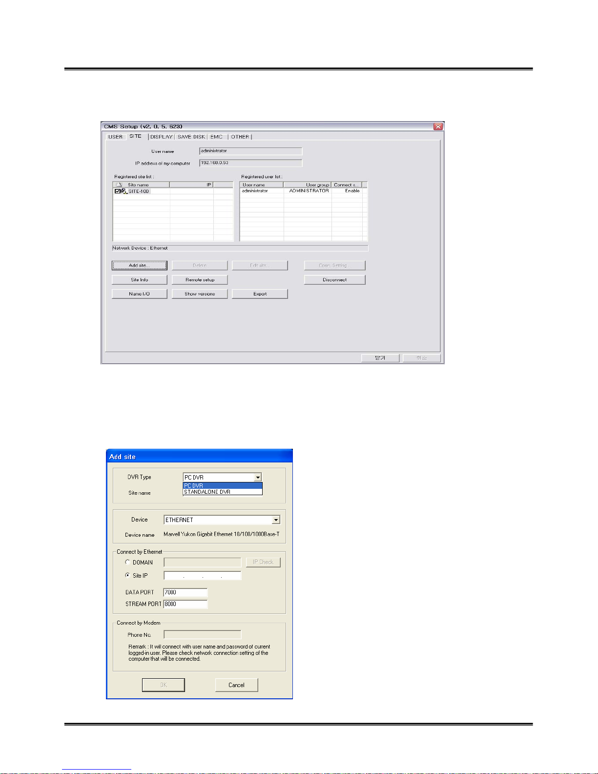
z SITE : setup the network connection.
¾ Uer name & IP address of my computer : displays user name and IP address of CMS user.
¾ Registered site list : displays the site which network setup is made.
¾ Registered user list : displays registered user with other information, user name, user group,
connecting device.
¾Add site : click to add network setup. Put
the user name, data port and stream port,
IP address, select device, and click OK. The
site will show up on ‘Registered site list’.
You can add the site maximum 255, and
you can select maximum 16sites for
simultaneous connection.
¾DVR Type : On the CMS, you can connect
PC DVR and Standalone DVR at the same
time. Select DVR type that you connect.
Page 58
58
¾ Delete : click it to remove the registered site.
¾ Edit site : edit setup information.
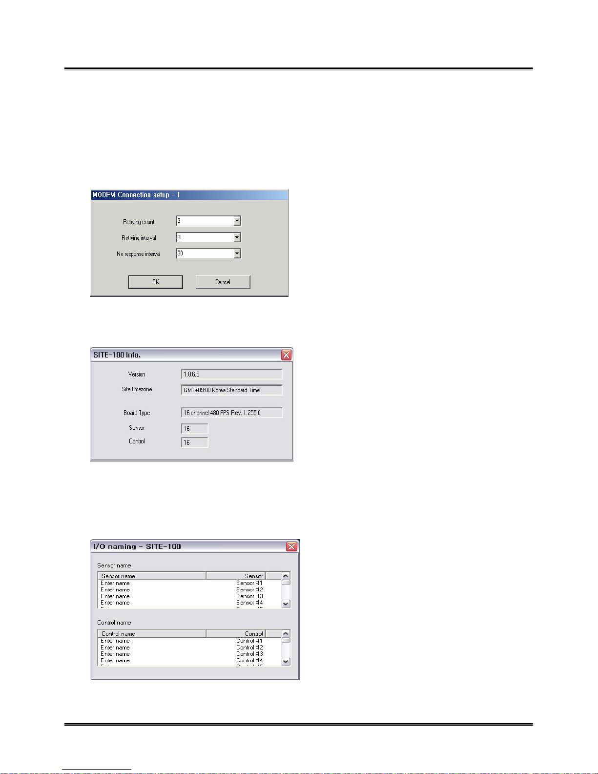
¾ Conn. Setting : it is for modem connection setup. You should setup Modem on OS, and this button
will be enabled. Adjust the time for retrying connection. If there is no response from the site system, the
system will retry connection as you set up.
¾ Site Info.: shows the information of connecting site, program version, time, capture card type, the
number of sensor and control.
¾ Remote setup : when the site is connected, you can setup the connected site as same as you do on the
site system.
¾ Name I/O : you can change the name of sensor and control. Double click ‘Enter name’, and it will be
enabled to put the name.
Page 59

59
¾ Show versions : shows the version of CMS currently using, click ‘Send site version’ to show the
information of site version.
¾ Pre-connect : when you compete the setup, click it to get the setup information from the site. It will
decrease connecting time with site.
¾ Export : export log of CMS to C\CMS_2\LOG.
Page 60

60
z DISPLAY
¾ Select a site and camera to display : maximum 255 sites can be registered, so select the site on
‘Site name’ and select one camera to display. The selected camera will be turned in red. If you
don’t select a camera, image can’t not be shown.
¾ Setup Pre-Memorize : it is very special function that you can make up maximum 255 different
setup in advance, so you can select any of setup and monitor. It means that you don’t need to
setup every time. Just select a setup and view the images. After you complete a setup, click’ +’ to
add, and this setup will show up on the box. Double click the name of setup, and it will be
enabled to change the name. Click ‘ ’ button to sort up the name in order of number or
alphabet character.
¾ PTZ info. : if the selected camera is PTZ, click it to check the camera inforamtion.
Page 61

61
z SAVE DISK
¾ Site name : select the save disk for each site.
¾ Frame rate : in order to manage save disk space, you can adjust frame rate from fifth to full.
¾ Site name : select the save disk for each site.
¾Save drive : select save drive.
Page 62

62
z EMC (Emergency Management Center)
¾ EMC mode : when the emergency event happen on the site, the event image is sent to CMS system
automatically with multiple or single screen.
¾ Enable EMC : checkmark to enable EMC. Select the event mode either by motion or by sensor or
control.
¾ Enable alarm sound : checkmark to enable alarm sound when EMC is activated. Open the folder and
select wave file.
¾ Auto pop-up : when EMC is activated by motion or sensor/control, the event will come up with
monitoring screen or single screen.
¾ EMC activation : after setup is completed, go to monitoring mode. Click ‘log out’ button, and you can
see ‘EMC standby’ button. Select it, it will go to EMC mode. EMC icon( ) will be generated on the
right corner of the bottom. When EMC mode is activated by motion or sensor/control, the event screen
will automatically pop-up, and the icon will be turn in red.
Page 63

63
¾ EMC single screen pop-up : automatically pop up with site name and camera number.
Page 64

64
¾ PTZ controller option : if you check ‘multiple controller’ that you have each controller for each
PTZ camera. ‘Single controller’ is one controller to manage all PTZ cameras.
¾ Tool tip : shows function explanation if you put the mouse on the function key.
¾ Digi-clock display format : select display format of digi-clock.
¾ Division 1 x 1 image size : the selected camera by mouse double click on the display screen, the
single camera will show up as 1 x 1 image size. Checkmark ‘Show full screen’, and then, it will
show up as full screen.
¾ Restore setting value from the latest registry backup file : if you need to restore the latest setting
value, you can apply it. In case you install new CMS on the same system, apply the latest setting
value, so you don’t need to setup again.
¾ Send list-message board to recycle bin : send the all message on ‘Message board’ to recycle bin.
¾ A time of auto-conversion : adjust time interval for auto-conversion.
¾ Auto reconnection : if network is unstable and disconnect for a period of time, CMS retry
connection with site system. Adjust waiting time and retrial count.
z OTHER
Page 65

65
Search
z On display mode, click ‘search’ button, and then the search screen will come up as below.
¾ Open folder : click the folder to select save drive. Select save drive, and click data folder.
¾ Calendar : click the date to search which is shown in blue bold line.
¾ Playback control buttons & screen division buttons : playback the data with various screen
divisions.
¾ Time table : it is a special time table to show data location with camera number and time zone. it
consists of ‘Hour zone’ and ‘camera zone’. Each hour zone consists of two balls. Left ball indicates
00~29, and right ball indicates 30~59 minutes. Designate data zone with or scroll bar. And
select the hour zone, the data zone will turn in pink. Playback the data with control buttons.
Page 66

66
¾ SAVE : it is the same as that of DVR Guard, please refer to it.
¾ Day Search : you can search data for an individual camera in more detail. Select date on the
calendar, and click ‘Day search’ button. It displays the data by 90 minutes. Double click one of them,
it displays the data by 10 minutes. Playback the data with control buttons. Click ‘Day search’ button
again to finish.
¾ Special search : it is an advanced search tool, you can search by single camera, event mode. Click
‘Special search’ button, ‘Advanced Search’ box will show up. Select search tool.
¾ Play Speed tool : adjust playback speed.
¾ Event search tool : search data by event. Checkmark the event mode.
Page 67

67
¾ Single –Camera search : select a camera, event mode, and hour. The data is showed by 1 minute. .
Remote Search
z You can search the data of the remote site, it is the same way as search function. Select a date on
the calendar. Select the camera and time zone on the time table, and playback with control buttons.
‘Special search’ is available on the bottom of the left hand side.
- Event search tool : Search by event type
- Single camera search : Data search in each camera
- Real time player : This is similar to Single camera search but audio playback is available only in
this function. Click the list marked with [s] and apply button for recorded
audio playback.
Page 68

68
17. Web CMS
¾ Web cms : Before you connect to the DVR, it will show ‘Security Warning’ message to ask you to
install Active X control.
Click ‘Install’ and download the file, and then it will allow to connect the system.
Page 69

69
z Connect Config : After you install Active X Control, this setup page will come out.
z Connect : Input all connection information DVR type, DVR side code, User ID & Password,
Network IP address Port number, and click ‘Connect. You can control PTZ with those PTZ icons.
¾ As soon as you put IP address on IE, it will ask you to execute Direct X. Click ‘Yes’.
¾ Put connection information, site code, IP address, user name and password.
z You can monitor DVR Guard on Internet Explore without installation of CMS. For security
reason, setup, search or more detailed functions are limited.
Page 70

70
18. e-Map Editor / Viewer
z It is a special tool to make single or multiple e-Map single, in addition, you can view it at remote
site. You can monitor the current activation of camera, sensor and control on the map. There is a
shortcut for e-Map editor/viewer on DVR Guard, click it to open it. It shows e-Map viewer
with e-Map of the system if it has already. Click ‘EDITOR’ button to execute it.
e-Map Editor
Page 71

71
¾ New : click it to make new e-Map. There are site and CMS
bmp file. Select either of them.
¾ Open : you can select e-map file to edit.
¾ Save : save e-map you made.
¾ Save as : save e-map with different name or location.
¾ Close : close e-map.
¾Exit : exit the program.
¾ Map Mode : select map mode either Site map or CMS map.
¾ View : you can check the state of each item. For example,
select camera state, and then all cameras on the map will light
up. Camera, sensor, and control state are enabled to check only
on site e-map editor. ‘Site state’ is enabled to check only on
CMS.
¾ About : shows the version of e-map editor.
Page 72

72
¾ camera, control, sensor icons : items to make map.
¾ virtual sensor : you can put virtual sensor, so when a real
sensor is activated, this virtual sensor is activated at the same
time. It helps to attract attention of the operator when the
event is detected.
¾ Site : you can use this icon for CMS e-map editor mode.
Select ‘CMS mode’ on map mode, and then this icon will be
enabled. Get CMS e-map and put this icon to show the location
of the site.
¾ Site info : put the site information such as site name, IP
address, memo.
¾ recycle bin : remove items from the map, click the item and
drag into recycle bin. Or click all item to remove, and click
‘Del’ key.
¾ Site icon : on ‘CMS map mode’, get the e-map from the browse, and put the site icon
on the location of the site.
Page 73

73
¾ Site info : put the site information.
¾ Property : put simple memo of each item if you need. Double click the item to show the
box. You can put maximum 19 characters.
Page 74

74
e-Map Viewer
¾ Viewing List : displays the list of listed camera, sensor and control with its ID. The selected
camera will be turned in red color on the list and e-Map. The selected camera will show up on
the display screen.
¾Site info. : shows site information with name, IP address, memo if it has.
¾ Sensor/ control : displays the status of activation in real time on the list. You can control
them on the e-Map as well. Click the item on the e-Map or list to activate.
¾ e-Map : put the mouse on the each item to see item information as tool tip.
z Site viewer
Page 75

75
z CMS viewer
¾ Viewing List : all sites listed on CMS are shown on the list. You can check the connection
status of them in real time. When the site item is detected, the site will light up. Click the site
item and then you can open the e-map of the site. Therefore you can check the status all items
on the e-Map.
 Loading...