

Page 1

Installation and Operation Manual
for
Speed Dome Camera
15-CD53/53W
VER:1.1
Please read the operation manual carefully
before installing and using this unit
Page 2

15-CD53 Packing List
No. Name QTY/ Unit Remark
1 Speed Dome Camera 1
2 AC24V power supply adapter 1
3 English Operation Manual 1
2
Page 3

15-CD53W Packing List
No. Name QTY/ Unit Remark
1 Speed Dome Camera 1
2 AC24V power supply adapter 1
3 English Operation Manual 1
4
5
6
7
8 5mm Hexagon socket wrench 1
Wall Mount Bracket
M6×14 stainless steel hexagon socket
screw
Φ
6 spring washer 4
Φ
6 flat washer 4
1
4
9 3mm Hexagon socket wrench 1
3
Page 4

SPECIFICATION
Items
Zoom Camera CZ55HM CZ55HCM
Image Sensor
Pixels
Horizontal resolution 480TVL
Video Output 1Vp-p Composite Video(75Ω)
SYNC System
Lens
Zoom
S/N Ratio
15-CD53 15-CD53W
1/4” Super HAD CCD
NTSC:768(H)x494(V)/PAL:752x582(V)
Internal/External (V-Lock)
3.9mm(Wide)~85.8mm(Tele)
220X (22X Optical,10X Digital)
48dB
Mini.Illumination
Picture Effect
White Balance
Gain
AE Control
Pan
Tilt
Preset
Auto Cruise
Power Source
0.05Lux 0.03Lux
Posi./Nega/Freeze/Cross Line/Mask Motion Detect/H/V Reverse
Auto(ATW Or AWB)
Auto(24dB)
Auto/Fix
Pan Range 360 Degree,Speed 0.5~240 Degree/s
Tilt Range 0~100 Degree, Speed 0.5~120 Degree/s
128 Preset Positions (Max)
1 Auto Cruising Tracks (Max)
AC24V / 2A
Operating Temp.
Weight Approx 1.4Kg Approx 4.5Kg
Dimensions Φ133.2×178mm (H) Φ200×336mm (H)
0℃~+50℃ -30℃~+50℃
4
Page 5

CONTENTS
1. PRECAUTIONS-------------------------------------------------------- 7
2. OPERATION---------------------------------------------------------------8
2.3 PRESET FUNCTION ---------------------------------------------------------------9
2.4 TOUR FUNCTION ------------------------------------------------------------------9
3. ID SETTING-------------------------------------------------------------13
3.1 120Ω TERMINATION SETTING ------------------------------------------------14
4. PROTOCOL SETTING----------------------------------------------- 14
5. CONSTRUCTION----------------------------------------------------- 14
5.1 INDOOR SPEED DOME CAMERA-------------------------------------------- 14
5.2OUTDOOR SPEED DOME CAMERA----------------------------------------- 15
6. TROUBLESHOTING------------------------------------------------- 16
7. CABLING AND CONNECTION OF RS 485 DATA BUS--- 17
8. INSTALLATION-------------------------------------------------------- 18
8.1 INDOOR SPEED DOME CAMERA-------------------------------------------- 18
8.2OUTDOOR SPEED DOME CAMERA-----------------------------------------19
9. CAMERA OSD MENU-------------------------------------------- 23
5
Page 6
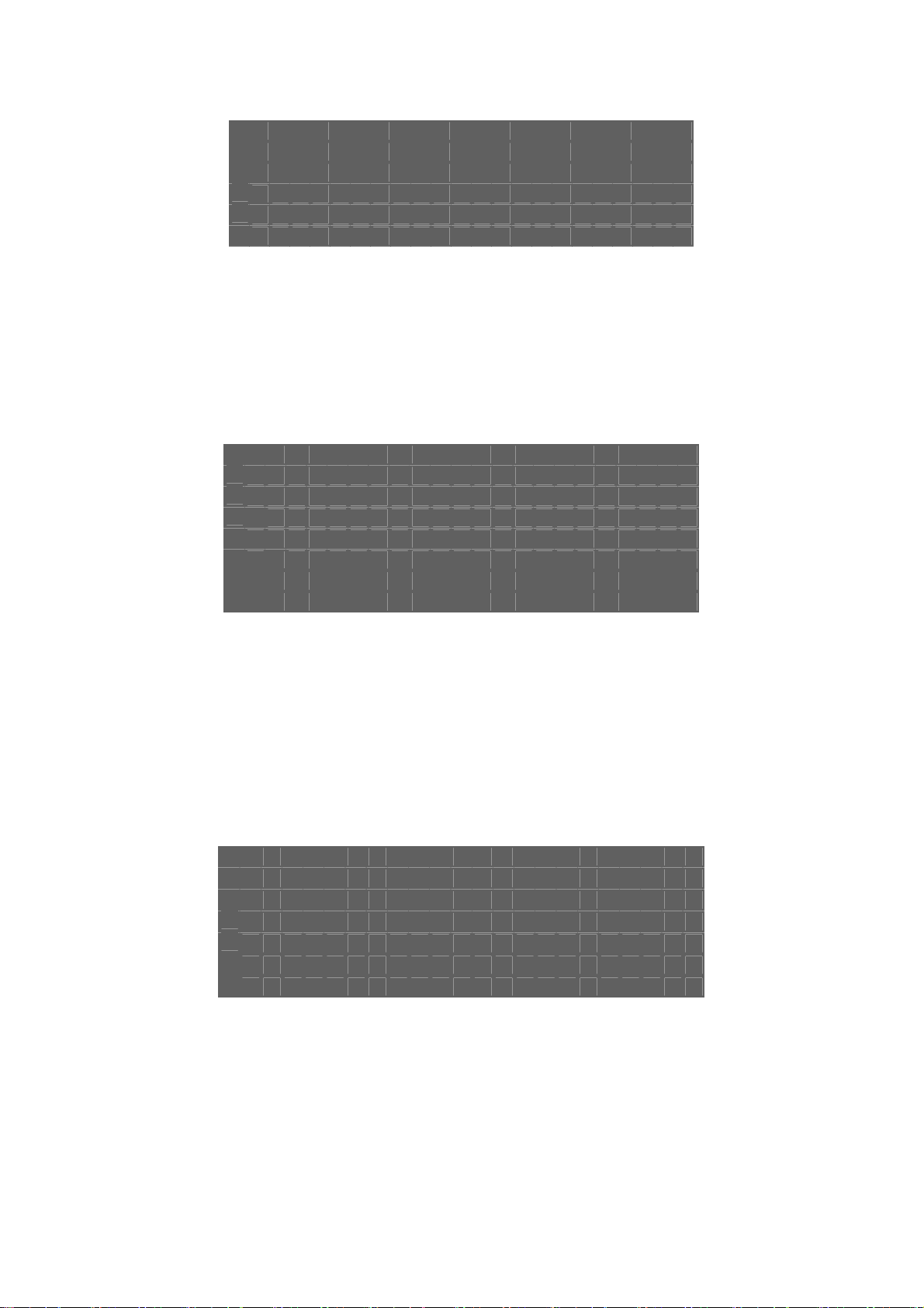
Table of 24VAC Cable Diameter and Maximum Power Transmission distance
The following table shows the cross sectional area of cable required to transmit power over the longest cable run allowed
before the maximum permitted volt drop is exceeded. (When using AC powered equipment the maximum allowed
voltage drop is 10%). For example: Equipment with a power rating of 80VA installed 10m away from the transformer
demands the minimum cable diameter of 0.8mm (square meter).
Warnings!
● Lightning proof equipment must be installed when the speed
dome camera is installed in open area.
● Make sure the input voltage and normal rated power before
powered up.
Cable Diameter (mm) Square Meter
Feet(m)
VA(W)
10 283(86) 451(137) 716(218) 1811(511)
20 141(42) 225(68) 358(109) 905(275)
30 94(28) 150(45) 238(109) 905(275)
40 70(21) 112 (34) 179(54) 452(137)
50 56(17) 90(27) 143(43) 362(110 )
60 47(14) 75(22) 119 (36) 301(91)
70 40(12) 64(19) 102(31) 258(78)
80 35(10) 56(17) 89(27) 226(68)
90 31(9) 50(15) 79(24) 201(61)
100 28(8) 45(13) 71(21) 181(55)
110 25(7) 41(12) 65(19) 164(49)
120 23(7) 37(11) 59(17) 150(45)
130 21(6) 34(10) 55(16) 139(42)
140 20(6) 32(9) 51(15) 129(39)
0.8000 1.000 1.250 2.000
150 18(5) 30(9) 47(14) 120(36)
160 17(5) 28(8) 44(13) 113 (34)
170 16(4) 26(7) 42(12) 106(32)
180 15(4) 25(7) 39(11) 100(30)
190 14(4) 23(7) 37(11) 95(28)
200 14(4) 22(6) 35(10) 90(27)
6
Page 7

1. PRECAUTIONS
1 Do not attempt to disassemble the camera.
To prevent electric shock, do not remove screws or covers.
There are no user-serviceable parts inside.
Ask qualified service personnel for servicing.
2 Handle the camera with care.
Do not abuse the camera. Avoid striking, shaking, etc. The camera could be damaged by improper handling or storage.
3 Do not use strong or abrasive detergents when cleaning the camera body.
Use a dry cloth to clean the camera. If dirt is hard to remove, use a mild detergent and wipe gently. Care should be taken
not to scratch the dome when wiping it. Afterwards, wipe off any excess detergent with a dry cloth.
4 Never face the camera towards the sun.
Do not aim the camera at bright objects. Whether the camera is in use or not, never aim it at the sun or other extremely
bright objects. Otherwise, blooming or smear maybe caused.
5 Never face the camera towards a place exposed to strong light sources for a long time.
Strong light sources such as spot lights can cause burn-in on the display screen, part of the image may discolour when
changing the view of the camera etc. due to deterioration of colour filter in CCD
6 Do not install this camera upside down.
This camera is designed for mounting on the ceiling or wall. Using this camera installed upside down, for example,
mounted on the floor, may cause malfunction.
7 Do not operate the camera beyond the specified temperature, humidity or power source ratings.
Do not use the camera in an extreme environment where high temperature or high humidity exists. Do not place near
heat sources such as radiators, stoves or other units that produce heat.
Use the Indoor Speed Dome camera under conditions where temperature is between -10°C - +40°C, and humidity is
below 90 %. The input power source is AC24V.
8 Do not install the camera near the air out-let of an air conditioner.
The lens may become cloudy due to condensation if the camera is used under the following conditions:
• Rapid temperature fluctuations by switching the air conditioner on and off
• Rapid temperature fluctuations due to frequent door opening and closing
• An environment where warm humid air may fog up the dome cover
• In a room filled with cigarette smoke or dust.
If the lens becomes cloudy due to condensation, remove the dome cover and wipe all moist surfaces with a soft
cloth.
9 Consumables
Components having moving parts such as the lens-drive motors, cooling fan motor and slip-rings built inside the camera
are subject to wear with time. Please ask the nearest service center about replacement and maintenance of such parts
10 Do not aim the camera at the same object for a long time.
Burn-in of an image may be caused on the fluorescent screen of a CRT monitor.
7
Page 8

2.OPERATION
Normal Operation:
2.0 Initial Power-up.
On initial power up the speed dome camera will conduct a power-on-self-test, at the end of the self-test the monitor will
momentarily display the following:
“P:P_D,ID:001,V:2a1”.
The Protocol and ID code will be displayed according to the installer’s preference.
2.1 Camera Function
2.1.1 Pan/Tilt Function
The camera is capable of moving vertically through 0-100°and horizontally endlessly through 360°. The Pan/Tilt speed
is variable depending upon the given amount of joystick deflection when using a proportional joystick controller.
2.1.2 Colour/Mono
When a Day/Night module is fitted it is possible to switch between the cameras colour and mono settings manually
To manually switch to Mono press [PRESET] + [67] + [ENTER]
To switch back to colour press [CALL] + [67] + [ENTER]
2.1.3 Digital Zoom
To enable the digital zoom function press [CALL] + [58] + [ENTER], To disable the digital zoom function press [PRESET]
+ [58] + [ENTER],
For full list of operation commands see section 2.9
2.2 Lens Function:
2.2.1 Zoom Lens Function
To adjust the focal length (viewing angle of the camera - zoom in / zoom out) – press [TELE] or [WIDE].
2.2.2 Focus Function
The camera will automatically focus but in some special circumstance, operators need focus manually, press [NEAR] or
[FAR] to manually the focus and press [CALL] + 59 + [ENTER] or operate the joystick to return to the auto mode.
2.2.3 Iris Function
In normal operation the iris will adjust automatically. If operators need to change the iris level manually, they can press
[OPEN] or [CLOSE] to adjust. Press [CALL] + 60 + [ENTER] or operate the joystick, to return to the auto mode.
2.3 Preset Function:
The speed dome camera is capable of storing and calling up to 128 preset positions. Each preset has its own P/T/Z and
focus settings. Note: Preset positions 50-66 are reserved for auxiliary function commands (see section 2.9).
Programming Note: To program preset positions the following commands are carried out based on using a COP
15-AU40E or 15-AU40H joystick/keyboard controller. If you are not using COP control equipment for the PTZ
operation of the CD53 speed dome please refer to the manufactures instruction manual for the equipment you
are using for the equivalent commands.
2.3.1 To set a preset position
Press [PRESET] + nnn + [ENTER], the onscreen display shows: SET PRESET :nnn
nnn = the number of the preset position: 1~128
2.3.2 To call a preset position
When preset camera positions have been programmed, you can enter the preset number to manually view the position.
8
Page 9

Press [CALL] + nnn + [ENTER], the onscreen display shows: CALL PRESET:nnn
nnn = the number of the preset position: 1~128
2.3.3 To delete a preset position: (Only be effective to Protocol COP-2. Some special keyboards no function)
Press [CLEAR] + nnn + [ENTER], the onscreen display shows:CLEAR PRESET :nnn
nnn = the number of the preset position which will be deleted.
2.4 Tour Functions:
2.4.1 To perform a preset sequence tour:
Press [CALL] + 53 + [ENTER], will scan automatically from No. 1 preset in order through to No. 16 preset position. The
cruise will not scan positions that are un-preset or deleted. The dwell time for each preset position is fixed at 3 seconds.
2.4.2 To perform a Horizontal Point to Point scan function (Auto Pan):
Move camera to view start position - Press [AUTO] + [ON] To select the start position of the horizontal scan
Move camera to view the end position - Press [AUTO] + [OFF] To select the stop position.
Press [AUTO] + [ENTER] To start the scan function.
The camera will scan automatically between two designated positions, namely “starting point” (left) and “end point” (right).
The dwell time at “starting point” and “end point” is 3 seconds; states of dome camera are shown below. The dome
camera will stop scan and implement new action when receiving qualified command.
Note: The dome camera may result in accumulative deviation in parameters after operating the scan for a long period.
The starting point and end point of scan shall be reset on a regular basis or as part of a planned maintenance program.
2.5 Auto Resume
2.5.1 Auto Resume Tour (Auto Home)
To enable the camera to resume it’s preset tour after a period of 5 minutes inactivity on the joystick keyboard controller
press [CALL] + [90] + [ENTER] to disable the feature press [PRESET] + 53 + [ENTER]
2.6 Title Display:
2.6.1 Zoom status confirmation display
This on screen display shows the current position of the Zoom lens i.e “ZOOM X 18”. To remove “ZOOM x nn” from the
display – Press [CALL] + [64] + [ENTER] to enter the Hitachi camera module OSD menu set-up (page 29).
2.7 Special Function:
2.7.1 Power-off Protection
When the camera is operating a scan or cruise track and a power failure occurs, the camera will store the operation it
was functioning before the power-off. When power is reapplied, the camera will continue to perform the scan or cruise
track automatically under the same state before power-off. Should scan or cruise track not be operating before power-off,
the camera will move to the first preset position automatically after power on self test routine.
Note: This is a fixed function and cannot be disabled.
2.8 Camera Reset
Press [PRESET] + [54] + [ENTER] to reset camera titles and settings.
9
Page 10

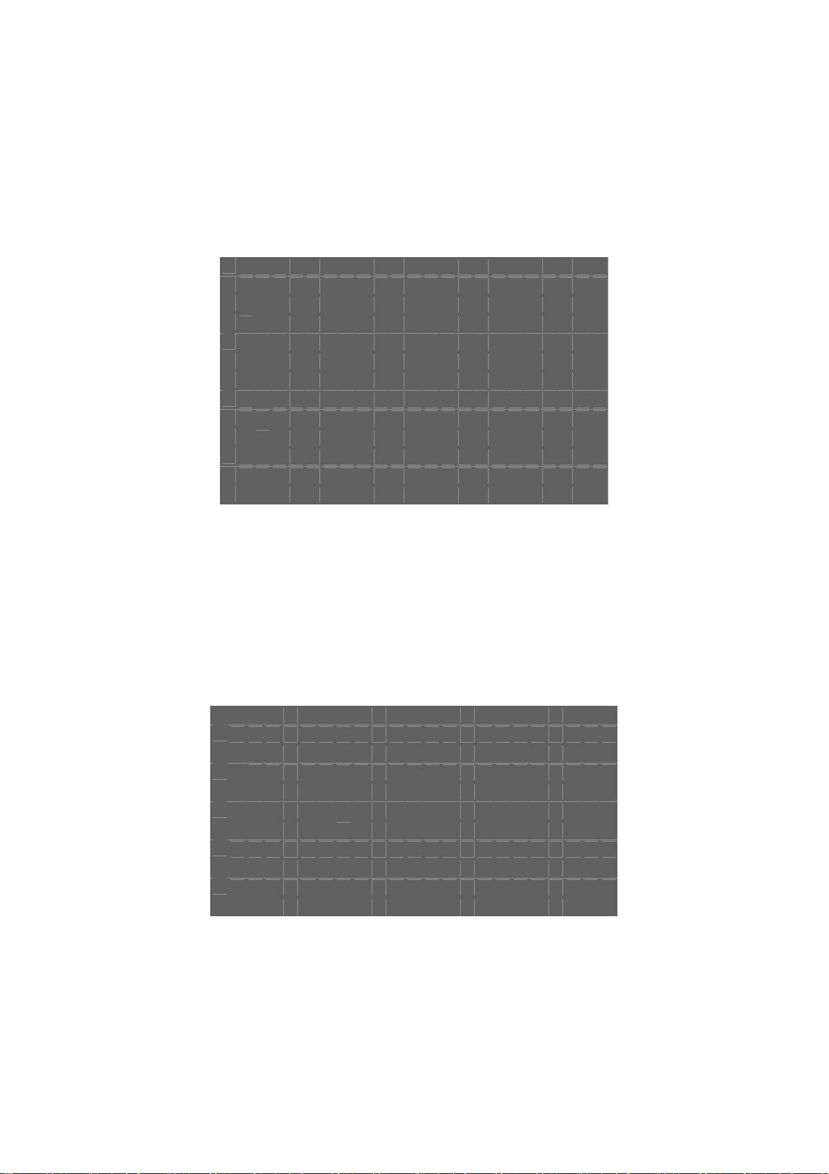
2.9 Auxiliary Functions List –
The commands shown are based on 15-AU40E and 15-AU40H Joystick/Keyboard controllers. Note: “F1” key =
“Menu” on 15-AU40ES keyboards.
Operation Function
F1 + 0 + Off Camera reset
F1 + 1 + On Backlight compensation ON
F1 + 1 + Off Backlight compensation OFF
F1 + 2 + On LOW illumination ON
F1 + 2 + Off Auto LOW illumination
F1 + 3 + On Menu/Display ON
F1 + 3 + Off Menu/Display OFF
F1 + 4 + On Digital zoom ON
F1 + 4 + Off Digital zoom OFF
F1 + 5 + On Keyboard LCD display Back Light ON
F1 + 5 + Off Keyboard LCD display Back Light OFF
F1 + 6 + On Auto FOCUS
F1 + 6+ Off Manual FOCUS
F1 + 7 + On Auto IRIS
F1 + 7+ Off Manual IRIS
F1 + 8 + On Auto White balance (AWB)
F1 + 10 + On White balance Auto follow model (ATW)
F1 + 11 + On Color picture
F1 + 11+ Off B/W picture
10
Page 11

Operation Function
Call + 33 + Enter Pan 180°
Call + 51+ Enter Scan start
Preset + 51+ Enter Set the start position of scan
Call + 52+ Enter Scan stop
Preset + 52+ Enter Set the end position of scan
Call + 53 + Enter Auto cruise from No.1 preset position to NO.16 preset position
Preset + 53+ Enter Carry out self-test
Preset + 54+ Enter Camera reset
Call + 55+ Enter Backlight compensation ON
Preset + 55+ Enter Backlight compensation OFF
Call + 58+ Enter Digital zoom ON
Preset + 58+ Enter Digital zoom OFF
Call + 59+ Enter Auto FOCUS
Preset + 59+ Enter Manual FOCUS
Call + 60+ Enter Auto IRIS
Preset + 60+ Enter Manual IRIS
Call + 61+ Enter
Preset + 61+ Enter
Auto White balance (AWB)
White balance Auto follow model (ATW)
Call + 63+ Enter Image Mirror ON
Preset + 63+ Enter Image Mirror OFF
Call + 64+ Enter Enable camera on screen menu function
Preset + 64+ Enter Disable camera on screen menu function
Call + 67+ Enter Color video
Preset + 67+ Enter B/W video
Call + 90+ Enter Enable Running SEQ after five minutes
Preset + 90+ Enter Disable Running SEQ after five minutes
Call + 95+ Enter Camera menu ON
Preset + 95+ Enter Camera menu OFF
11
Page 12

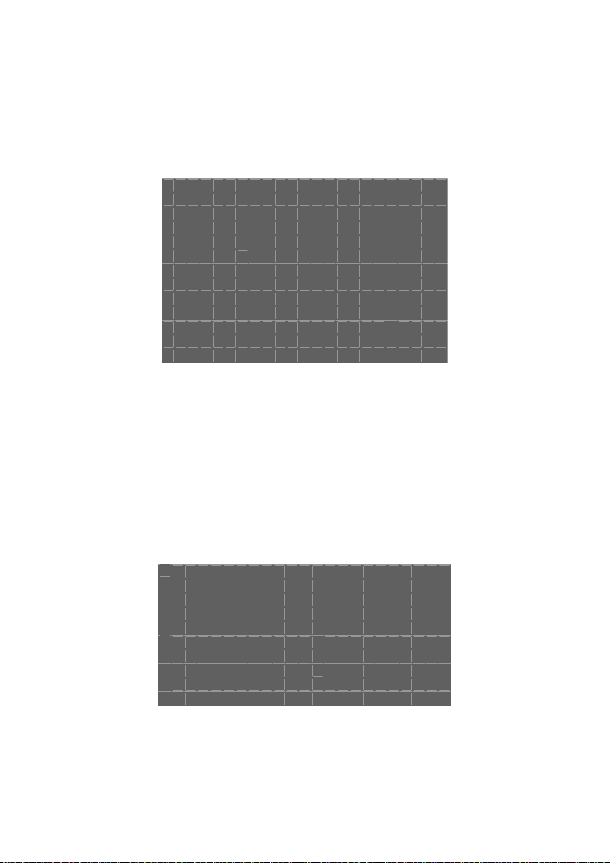
Operation Function
Call + n + Enter To call the number N preset position
Preset + n + Enter To set the number N preset position
Preset + n + Off Delete the number N preset position
Cam + n + Enter Select the speed dome address “n” to be controlled from keyboard
Shot + n + Enter N=1:Auto the cruise track
Shot + n + Off N=1:Stop the cruise tracks
Auto + On
Set the start position of auto pan
Set the end position of auto pan
Auto + Off
Auto + Enter
The camera will move from the auto pan start position to the auto
pan end position
Wide ZOOM wide
Tele ZOOM tele
Far FOCUS far
Near FOCUS near
Open IRIS open
Close IRIS close
12
Page 13

3.ID SETTING
The ID of this speed dome is set by the binary coded 10-way switch. Below is the detail of setting ID code:
¯¯¯¯¯¯¯¯¯¯¯¯¯
13
Page 14

3.1 RS485 TERMINATION SETTING
Note:It is possible to connect multiple speed dome cameras in parallel provided that No. 10 switch ID code of the
farthest camera is set to “ON”. The switch will apply a 120Ω impedance offset resistance. The operation is also required
for a single camera especially when the installation has long cable runs.
The No. 10 ID code should be set to “ON” for the last camera connected to the daisy chain to set at 120 Ω.
4.PROTOCOL SETTING
Protocol of this speed dome is set through a 3 segment DIL switch.
Below is the detail of setting protocol code:
NOTE: THE BLACK SEGMENT REPRESENTS THE SWITCH (NOT THE WHITE SEGMENT).
Power off before changing settings - DO NOT Power on until setting change is completed!
Protocol setting
5. CONSTRUCTION
5.1 Indoor Speed Dome Camera
Dome Camera mounting base
AC24VInput
Video Output
RS485data
Dome Housing (twists off
anti-clockwise to access fixing
positions.
Camera
14
Page 15
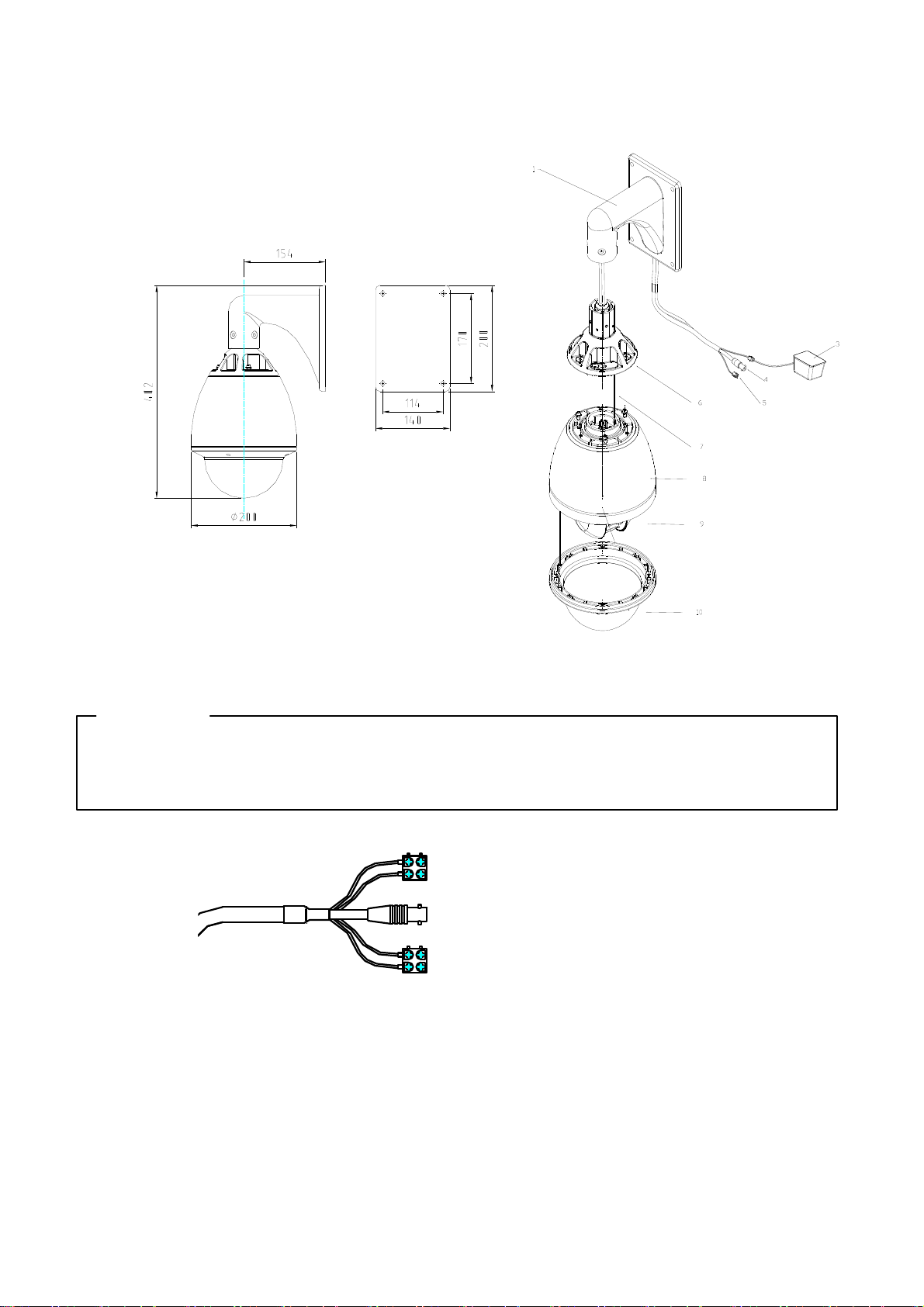
5.2 Outdoor Speed Dome Camera
1 W all Mount
3 AC24V Input
4 Video Output
5 RS485 data
6 Outdoor Dome Flange
7 Safety Lanyard
8 Aluminum Die Cast Housing
9 Camera
10 Acylic dome
◆ CONNECTIONS
PRECAUTIONS
※ The following connections should be made by qualified service personnel or system installers in
accordance with all local codes.
Red L AC24V
Black N AC24V
Video Output
Orange RS485+
Note: When powered up, the camera performs a self-check for about 2 minutes (including one panning, tilting, zooming
and focusing operation). During the period, control operations are not executed.
Yellow RS485-
15
RS485 Signal
Page 16
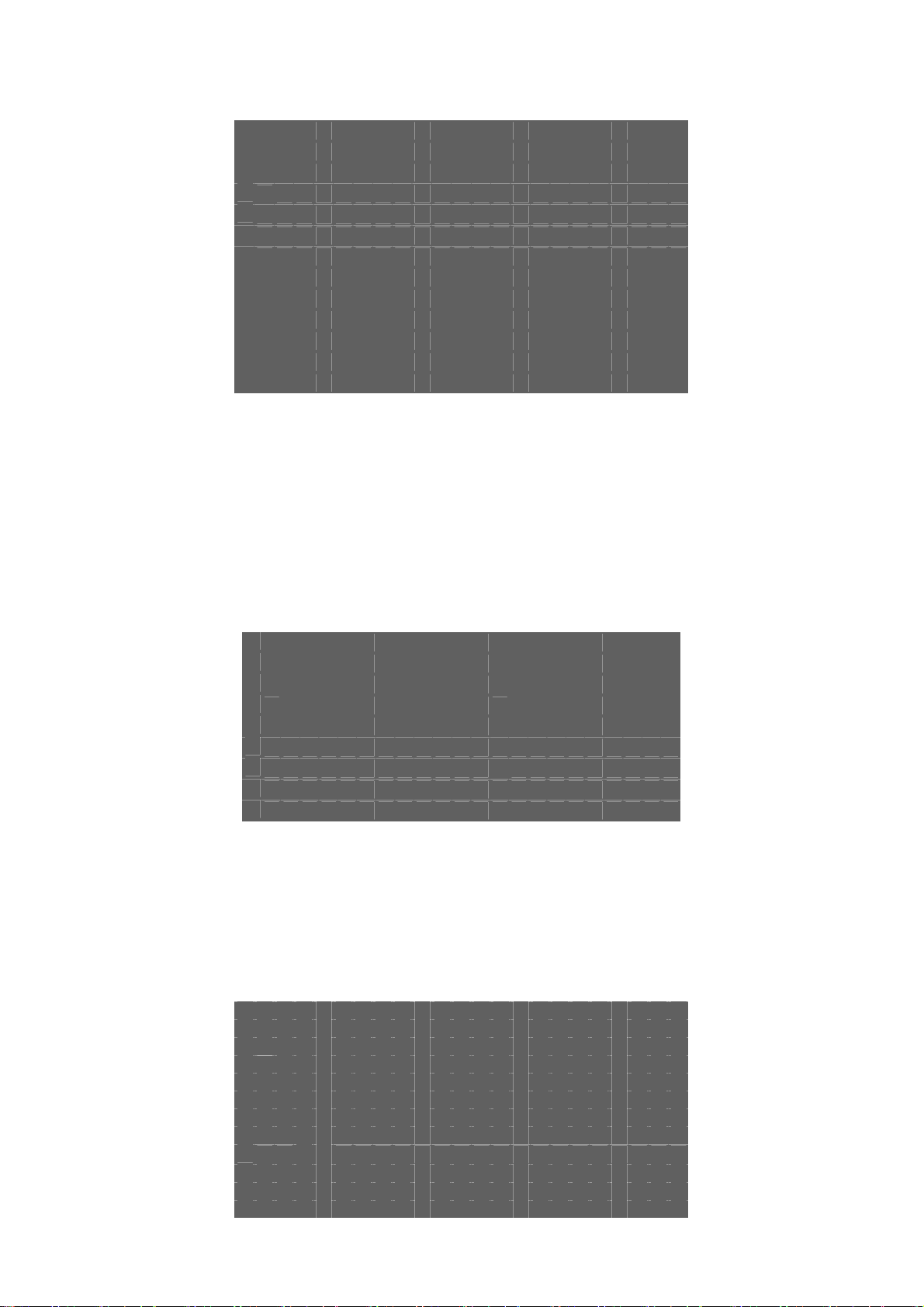
6. TROUBLESHOTING
Trouble Possible Causes Solution
No self check, no video after
power up
Self-check isn’t normal, but
image is normal and
obstacle found in operation.
Self-check is normal but no
image
Self-check is normal but it is
uncontrollable
Power supply failure Replace
Cabling/connection problems Investigate and repair/replace as necessary.
Volt drop. Replace cable with correct cross sectional area
Mechanical failure Repair
The camera is out of position Put straight
Supply Voltage is low at camera
The contact of video cables is incorrect Correct
The contact of video cables is loose Repair
Camera is damaged Replace
The connection of control signal is incorrect Correct
Camera number is not set correctly. Reset dip switches to correct address
Protocol setting is incorrect Reset DIP switches to correct protocol
RS485 cable A+&B- connection is not correct Correct
RS485 cable is too long
RS485 cable wrong type Change Rs485 cable to Cat5 cable
Install power supply nearer to the camera or
install a larger cross sectional area power cable
from the transformer to camera.
The maximum cable for RS485 communication
is 1.2km
RS485 signal network is star configuration
The contact of video cables is loose Repair
Unstable image
Voltage is low Replace
Dropout occurs due to low voltage
Self-check is abnormal Power up again
The camera is
uncontrollable and running
unceasingly
Abnormal video Extremely bright video No termination or high resistance
The operation of mainframe is not correct Power up again
RS485 cable wrong type Change Rs485 cable to Cat5 cable
RS485 bus line isn’t equipped with matched
resistance, or the resistance is not matched.
Install Star card distributor at junction of
connection
Install power supply nearer to the camera or
install a larger cross sectional area power cable
from the transformer to camera.
Correct termination settings
16
Page 17
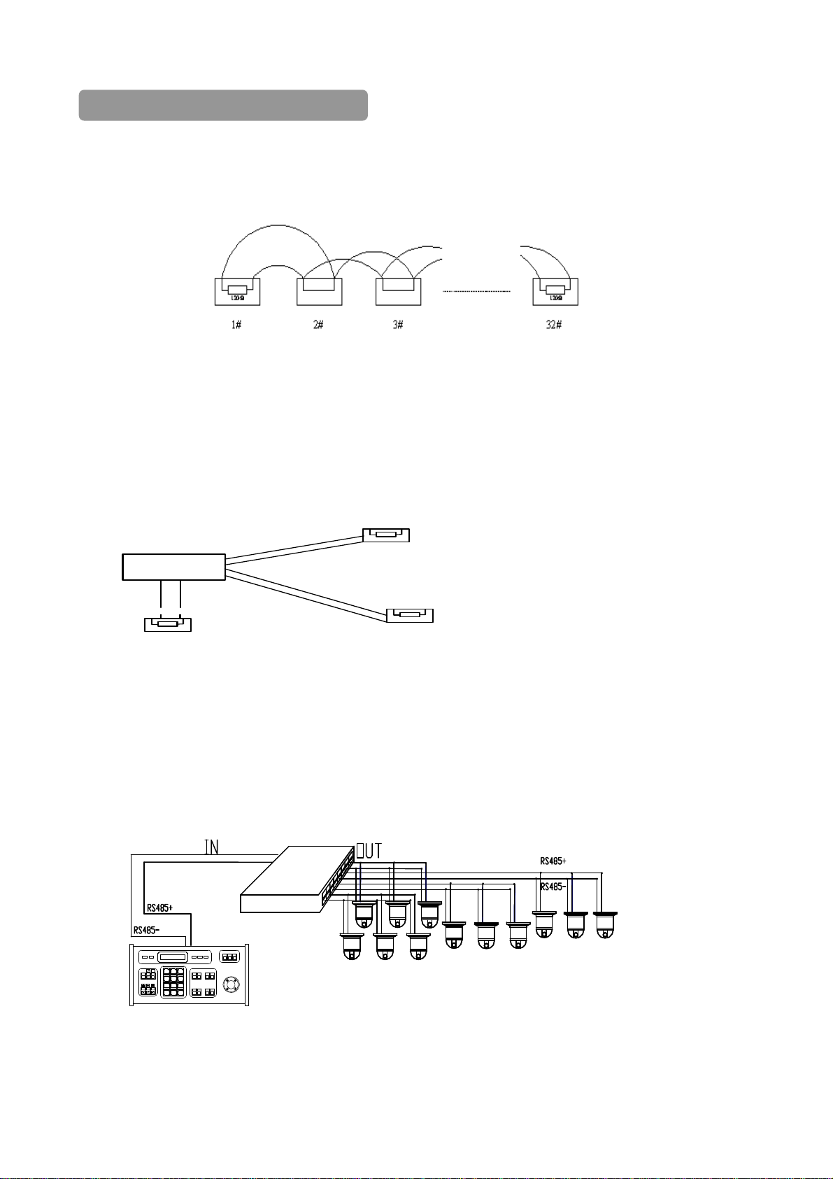
7. CABLING AND CONNECTION OF RS485 BUS
1. Characteristics of RS485 Bus - As specified by RS485 standards. RS485 Bus is half-duplex data transmission
cables with characteristic impedance of 120 ohms. The maximum load is 32 unit loads (including main controller and
controlled equipment.) The RS485 standard requires a single twisted pair daisy-chain connection between the equipment.
There must be a termination resistor of 120 ohms impedance at both ends of the connection (refer to the following
FIGURE).
When No.10 Dip Switch is set to “ON”, the camera 120 ohm termination resistor is connected.
2. Cable run - The maximum length of the installation cable run depends upon the protocol baud rate selected. Approx
Max transmission distances using 24awg twisted pairs are as follows:
2400bps = 1800m, 4800bps = 1200m, 9600bps = 800m
3. Using a more practical cabling configuration - In some circumstances for ease of installation the cabling route
adopts a “star” configuration. The termination resistors must be connected to the two pieces of equipment that are
farthest away from each other (see diagram below). NOTE: This method of installation does not meet the RS485
standards and issues with the PTZ performance can occur.
Control
120Ω
1#
120Ω
12#
120Ω
6#
Some problems, such as signal reflection and lower anti-interference performance can easily occur and result in the
decline of reliability in the control signal. The result can be that the camera is out of control completely or operation is
interrupted or operates automatically and fails to stop, etc. In such circumstances the manufacturer recommends the
RS485 Signal Distributor 15-MX08.
The distributor changes the star configuration connection to a compatible mode of connection stipulated in the RS485
standards. The new connection achieves reliable data transmission.
RS485 Distributor cabling example -
4
S
R
r
to
u
b
i
r
t
i
s
D
5
8
Current CamID:001
7
456
123
Clear
89
0
F1 F2
SEQ PTZ/ MULX
WIDET EL E FAR NEAR
CAM/IDAUTO OPENCLOSE
Enter
ON
OFF
LIVE
TAPE
FUNC
PTZ & Mult i pl exer
CALL P RESET SHOT
F3
Each output port can connect 32 terminations, and practical connections must be considered.
17
Page 18
8. INSTALLATION
8.1 INDOOR SPEED DOME CAMERA
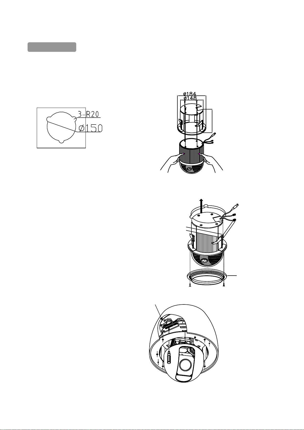
INDOOR EMBEDDED MOUNT(Option):
(1)Cut a hole in the ceiling. (2)Mount the Speed Dome in the
embedded bracket with 4 screws.
Max80
(3)Fit the embedded bracket into the mounting holes and
adjust 3 securing feet. Fix the embedded bracket
(4)Mount the plastic ring to the camera mounting base.
8.2 Outdoor Speed Dome Camera
Note: Protocol and ID code( fig. 1)
Protocol and ID
Pl a s t i c Ring
Fig. 1
18
Page 19

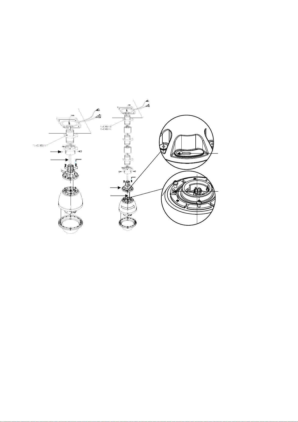
A. OUTDOOR WALL MOUNT
A1 WITHOUT POWER BOX (Fig 2)
① Disassemble the outdoor
flange and dome housing.
Select the Protocol and ID
code for the camera (fig.1) and
mount the dome housing as follows:
2
○
Fix the wall bracket into
Position and fit the outdoor flange
To the bracket neck with screws
supplied.
③ Connect all the cables as required.
④ Mount the Safety lanyard of the
outdoor flange onto the outdoor
speed dome. Align the guide pin
of mounting base at the longest
curved slot of the outdoor flange.
Twist into position, clockwise, and
tighten the screws.
A2 WITH POWER BOX (optional) (Fig 3)
① Disassemble the Outdoor
flange and dome housing.
Select the protocol and ID code
for the camera (fig.1) and
mount the dome housing as follows:
② Mount the power box onto a
solid surface. Mount the wall
bracket on the power box.
③ Fix the wall bracket to the
outdoor flange with the nuts provided.
Safety Hanging-Lock
④ Connect all the cables as required.
⑤ Mount the Safety lanyard of the
outdoor flange onto the outdoor
speed dome. Align the guide pin
of mounting base with the longest
curved slot of the outdoor flange.
Twist into position, clockwise, and
tighten the screws.
Longest
Curved slot
Outdoor Flange
Safety lanyard
Guide
Pin
Fig.2
Outdoor Flange
Longest Curved slot
Fig. 3
Guide Pin
19
Page 20
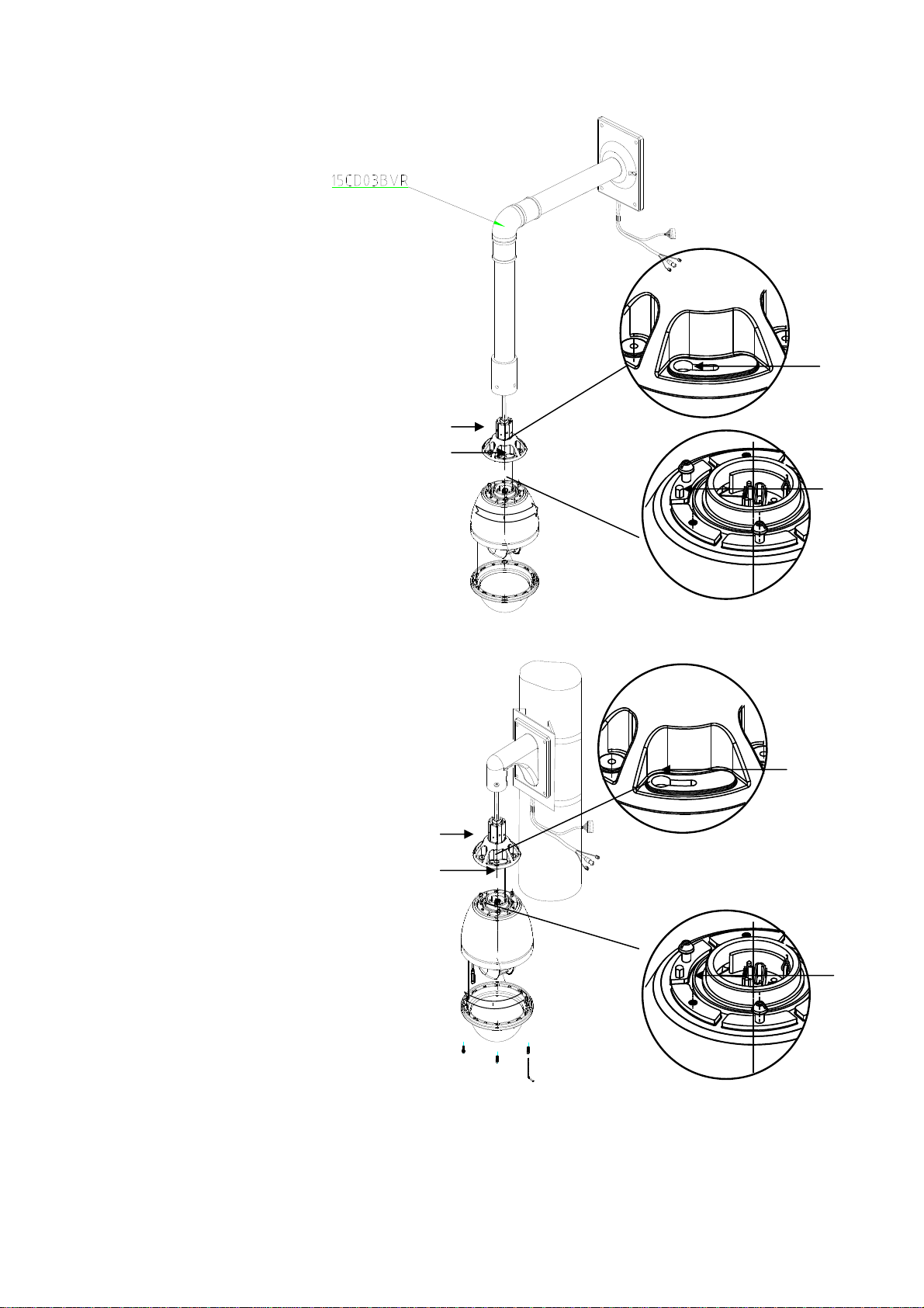
B. OUTDOOR CEILING MOUNT (Option) (Fig4 & 5)
① Disassemble the Outdoor Flange and dome housing. Select the protocol and ID code for the camera (fig.1), and
mount the dome housing as follows:
2
○
Fix the ceiling bracket assembly and fit the outdoor flange.
③ Connect all the cables as required.
④ Fit the Safety lanyard of the outdoor flange to the outdoor speed dome. Align the guide pin of mounting base with the
longest curved slot of the outdoor flange. Fix the speed dome onto the outdoor flange, twist into position clockwise ad
tighten the screws.
Outdoor Flange
Safety Hanging-Lock
Outdoor Flange
Safety Hanging-Lock
Fig. 4
Fig. 5
Longest Curved slot
Guide Pin
20
Page 21
C. OUTDOOR WALL MOUNT (Option) (Fig 4)
① Disassemble the outdoor
flange and dome housing.
Select the Protocol and ID
code for the camera (fig.1) and
mount the dome housing as follows:
2
○
Fix the wall bracket into
Position and fit the outdoor flange
To the bracket neck with screws
supplied.
③ Connect all the cables as required
④ Fix the Safety lanyard of the
outdoor flange onto the outdoor
speed dome. Align the guide pin
of mounting base with the longest
curved slot of the outdoor flange.
Twist into position, clockwise, and
tighten the screws.
D. OUTDOOR POLE MOUNT (Option) (fig 5)
① Disassemble the outdoor flange
and dome housing. Select the protocol
and ID code for the camera(fig.1)
and mount the dome housing as follows:
② Mount the pole bracket and fit the
wall bracket with the screws provided.
Mount the outdoor flange to the wall
bracket and tighten the screws.
③ Connect all the cables as required.
Outdoor Flange
Safety lanyard
④ Fix the Safety lanyard of the
outdoor flange onto the outdoor
speed dome. Align the guide pin of
mounting base with the longest
curved slot of the outdoor flange.
Twist into position clockwise and
tighten the screws
Longest Curved Chute
Outdoor Flange
Safety lanyard
Guide Pin
Fig. 4
Longest Curved
slot
Guide Pin
Fig. 5
21
Page 22

E. OUTDOOR CORNER MOUNT
(Option) (fig 6)
① Disassemble the outdoor flange
and dome housing. Select the protocol
and ID code for the camera(fig.1)
and mount the dome housing as follows:
2
○
Mount the corner bracket
and fit the wall bracket with
the screws provided, fix the
outdoor flange to the neck of
the bracket with the screws
provided.
③ Connect all the cables as required.
④ Fix the Safety lanyard of
the outdoor flange to the
outdoor speed dome.
Align the guide pin of the
mounting base to the
longest curved slot of
outdoor flange, twist into
position and tighten the screws.
F. OUTDOOR CORNER MOUNT
D1WITHOUT POWER BOX(Option)
① Disassemble the outdoor flange
and dome housing. Select the protocol
and ID code for the camera(fig.1)
and mount the dome housing as follows:
2
○
Mount the corner bracket
and fit the wall bracket with
the screws provided, fix the
outdoor flange to the neck of
the bracket with the screws
provided.
③ Connect all the cables
as required.
④ Fix the Safety lanyard of
the outdoor flange to the
outdoor speed dome.
Align the guide pin of the
mounting base to the longest
curved slot of the outdoor flange,
twist into position clockwise
and tighten the screws.
Outdoor Flange
Safety Hanging-Lock
Outdoor Flange
Safety Hanging-Lock
Longest Curved slot
Guide Pin
Fig. 6
Longest Curved Chute
Guide Pin
22
Page 23

9. Camera On Screen Display Function Menu.
Main Menu ( Page 1. )
S E T U P M E N U ( 1 / 3 )
Î
W H I T E B A L A N C E
I R I S
A G C ・ S E N S
B A C K L I G H T
E N H A N C E R
Z O O M ・ F O C U S
H / V R E V E R S E
T I T L E
P R E S E T
Main Menu ( Page 2. )
S E T U P M E N U ( 2
Î
P O S I T I O N
G A M M A
P O W E R O N
M A S K
O S D
Z O O M + A F
L A N G U A G E
C O M M
Main Menu ( Page 3. )
S E T U P M E N U ( 3 / 3 )
Î
F R E E Z E
P O S I / N E G A
/
3 )
M O T I O N D E T E C T
・
C R O S S L I N E
I D
23
Page 24
Sub Menu
White Balance
W H I T E B A L A N C E
Î
C O L O R O F F
O N
ÎA U T O
W B
G A I N
E X T
Î
A T W R - - - ■ - - B
A W B R - - - ■ - - B
Î
R-Y - - - - ■ - - B - Y - - - - ■ - - -
This is used to control the colour, white balance and the gain rate of RED & BLUE colour.
1. 「COLOR」selector:OFF is a monochrome image,ON is a normal colour image, display image will be
automatically changed to a monochrome image in low light.
2. 「WB」White balance control:ATW is Auto trace white and is recommended for normal use. AWB is one push
white balance and can be used as an alternative to ATW to provide better results in certain environments.
Push the [menu] key「AWB」to lock the current colour temperature.
「
AWB」will flicker while the camera locks the current colour temperature, when the process is finished the
flicker will stop.
3. 「GAIN」:The gain rate of R-Y & B-Y can be adjusted separately.
After setting, push [EXIT] key to go back to the main menu page.
IRIS
This is used to control the iris & shutter speed of the lens. It includes 3 items “PEAK”, “ALC”, “AES”.
1.「PEAK」is used to control the reaction of auto iris, which is based on the average light of the picture signal or
the light rate of the peak.
2.「ALC」is used to select AUTO or FIX to adjust IRIS level
3.「AES」is used to select electronic shutter using either the AUTO or FIX function. In FIX mode the shutter
speed can be slected at: [OFF],[1/100sec],[1/120sec],[1/250sec], [1/500sec],[1/1000sec],[1/2000sec]
[1/4000sec],[1/10000sec]
After setting, push [EXIT] key to go back to the main menu page.
I R I S
Î
P E A K ÎO F F
O N A ■ - - - - - P
A L C ÎA U T O - - - ■ - - F I X
A E S A U T O
ÎF I X O F F
- - - ■ - - -
- - - ■ - - -
,
24
Page 25
AGC・SENS
A G C ▪ S E N S
Î
A G C A U T O
S E N S A U T O
This is used to select the「AGC」and「SENS」function.
1.「AGC」:To adjust auto gain control, 0dB~24dB 9 steps adjustable.
2. 「SENS」:For low light application: 0 Frame,6 Frame,12 Frame,16 Frame,18 Frame,22 Frame,
24 Frame,30 Frame,36 Frame, 9 steps adjustable.
After setting, push [EXIT] key to go back to the main menu page.
- - - ■ - - -
■ - - - - - -
BACKLIGHT
B A C K L I G H T
Î
O F F
O N
Î
A R E A
S E N S L O W - - - - ■ - - - H I
This is used to control “BLC” (Back Light Compensation),
1.「BLC」ON / OFF selector. Selector「ON」has 2 sub-items:「AREA
2.「AREA」: 48 BLC zones can be set separatly. According to the mask area (BLC zone) signal to decide the iris
and shutter speed.
3.「SENS」:Is used to enhance the BLC effect.
After setting, push [EXIT] key to go back to the main menu page.
」,「
SENS」.
ENHANCER
E N H A N C E R
H ▪ G A I N - - - - - - ■ - - -
V ▪ G A I N - - - - - - ■ - - -
This is used to enhance the compensation of the picture quality.
1.「H • GAIN」:Horizontal Compensation
2.「V • GAIN」:Vertical Compensation
After setting, push [EXIT] key to go back to the main menu page.
25
Page 26
ZOOM・FOCUS
Z O O M ▪ F O C U S
Î
D I G I T A L Z O O M O F F
Z O O M S P E E D - - - ■ - -
F O C U S S P E E D - - - ■ - -
Z O O M W I D E T E L E
F O C U S
Î M A N U A L I N F N E A R
A U T O
This is used to control the motion of the lens, including “Digital ZOOM” ON/OFF and zoom level function.
1.「Digital ZOOM」selector:OFF、X2、X4、X6、X8、X10.
2.「ZOOM Speed」:Set the speed of the zoom.
3.「FOCUS Speed」:Set the speed of focus.
4.「ZOOM」:Lens ZOOM adjust WIDE / TELE
5.「FOCUS」:AUTO / MANUAL setting
After setting, push [EXIT] key to go back to the main menu page.
H/V REVERSE
H / V R E V E R S E
Î
H ▪ R E V E R S E
V ▪ R E V E R S E
This is used to select image「Horizontal Reverse」and「Vertical Reverse」function.
1.「H.REVERSE」:Horizontal Reverse (Mirror) ON/OFF
2.「V.REVERSE」:Vertical Reverse (Up-side down) ON/OFF
After setting, push [EXIT] key to go back to the main menu page.
Î
O F F
O N
Î
O F F
O N
TITLE (FEATURE NOT SUPPORTED)
T I T L E
Î0 1 2 3 4 5 6 7 8 9
A B C D E F G H I J K L M
N O P Q R S T U V W X Y Z
a b c d e f g h i j k l m
n o p q r s t u v wxy z
□
' " . , < > (
: ;
U P
D O W N
)
[ ] { } ┌ ┘ ─ *
/
26
Page 27
This is used to set up the ID figures & position on the screen. (Title setting)
1.TITLE start position selector.
2.TITLE Character selector.
3.TITLE display position UP or DOWN selector.
After setting, push [EXIT] key to go back to the main menu page.
RESET
R E S E T
Î
O F F
O N
I N I T I A L
O F F
ÎO N
P H A S E
ÎO F F
O N
─ - - - - - - ■ - - - - +
This is used to program the camera to return to “RESET”, “INITIAL”, or “PHASE” condition
1.「RESET」:When set to ON the camera will be reset and set to the default settings.
2.「INITIAL」select:Set to ON to save camera settings when there is a power loss or when the camera is reset. If this
setting is set to OFF the camera will revert to its default settings.
3.「PHASE」Set to ON ext-VD sync is enabled
After setting, push [EXIT] key to go back to the main menu page.
(“PRESET” IN SOME SOFTWARE VERSIONS)
MOTION DETECT (FEATURE NOT SUPPORTED)
M O T I O N D E T E C T
Î
O F F
O N
T I M E 1 0 S E C
6 0 S E C
S E N S L O W - - - ■ - - - H I
1. Motion detect ON / OFF select.
2. Motion detect area select.
3. Motion detect output time select.
4. Motion detect sensitivity adjustment.
After setting, push [EXIT] key to go back to the main menu page.
Î
3 0 S E C
This is used to select the motion detect function.
27
Page 28

POSITION (FEATURE NOT SUPPORTED)
P O S I T I O N
A L A R M N O = 0
F R E E Z E ÎO F F
O N
P O S I T I O N
ÎN O = 1
Z O O M S P E E D - - - ■ - F O C U S S P E E D - - - ■ - Z O O M W I D E T E L E
F O C U S I N F N E A R
This is used to set「ALARM-IN」function, either「ALARM POSITION」or「IMAGE FREEZE」.
1.「ALARM NO.」:Set alarm position(1~64),if set to (0) alarm position is not enabled.
2.「Freeze」:Set ON mode,「ALARM-IN」triggers the image freeze function.
3.「POSITION」:The alarm position has 64 steps (positions) that can be programmed. (This is the position the lens will
return to upon an alarm)
After setting, push [EXIT] key to go back to the main menu page.
GAMMA
G A M M A
Î
T Y P E 1
T Y P E 2
This is used to select the camera gamma correction.
「
GAMMA」select:TYPE-A gamma is 0.45, TYPE-B gamma is 1.0
After setting, push [EXIT] key to go back to the main menu page.
POWER ON
P O W E R O N
Î
B L U E B A C K
O F F
Î O N
P O S I T I O N
Î O F F
O N N O = 1
28
Page 29
This is used to select the camera power on state.
1.「BLUE BACK」:When this setting is turned ON a blue background will be displayed when power is
connected to the camera. If this feature has not been enabled a normal image will be displayed.
2.「POSITION OFF」: The lens position is set to its current position upon receiving power.
3.「POSITION ON」:The lens position is set to a preset position (1~64) upon receiving power.
After setting, push [EXIT] key to go back to the main menu page.
MASK (FEATURE NOT SUPPORTED)
M A S
Î
M A S K N O = 1
O N ÎH - S T A R T = 2 0
H - E N D = 2 0
V - S T A R T = 2 0
V - E N D = 2 0
C O N N E C TÎO F F
O N
This is used to select the mask area size and position for each lens position.
1. Lens position no. select(1~64)
2. MASK NO. select(1~4)
3. MASK area display ON / OFF select.
4. Hor. direction start position.
5. Hor. direction end position.
6. Ver. direction start position.
7. Ver. direction end position.
8.ZOOM action to link mask area, ON / OFF select..
After setting, push [EXIT] key to go back to the main menu page.
K
P O S I T I O N N O =
1
ÎO F F
OSD
O S D
Î
ÎO N
O N
Z O O M ▪ M A G
O N
This menu enables or disables the on screen Position, Motion, and Zoom notifications.
1. POSITION NO. display ON / OFF select.
2. MOTION action display ON / OFF select.
3. ZOOM times display ON / OFF select.
After setting, push [EXIT] key to go back to the main menu page.
P O S I T I O N O F F
M O T I O N
ÎO F F
ÎO F F
29
Page 30

ZOOM+AF
Z O O M + A F
Î
Z O O M + A F ÎO F F
O N
A F S L E E P
O N
Î
O F F
This setting controls how frequently the auto focus feature is used.
1. Zoom + AF: Turning this feature ON disables the zoom and auto focus function. The lens will focus once and then
maintain the current zoom and focus levels.
2. AF Sleep function ON / OFF select.
(AF Sleep function ON: If there is no movement on the screen for approximately 5 minutes AF sleep mode will be
activated. This will temporarily disable Auto Focus until a change in pixels is detected)
After setting, push [EXIT] key to go back to the main menu page.
LANGUAGE
L A N G U A G
Î
E N G L I S H
C H I N E S E
J A P A N E S E
This is used to select OSD menu display language.
OSD display language select, ENGLISH / CHINESE (Simple) / JAPANESE
After setting, push [EXIT] key to go back to the main menu page.
E
COMM・ID (FEATURE NOT USED)
C O M M ▪ I D
Î
C O M M ▪ I D = 1
M O D E Î1 : 1
1 : N
This is used to select communication ID and mode.
1. Communication ID number's set. (The ID must correspond with the ID number set on a joystick controller.)
2. MODE choice
1:1 : One controller to control one Camera.
(Supports single or multiple cameras)
30
Page 31

1:N : One controller to control many Cameras.
(Redundant feature)
After setting, push [EXIT] key to go back to the main menu page.
CROSS LINE
C R O S S L I N E
Î
O F F
O N
This enables / disables the cross line display.
Cross line ON/OFF select, set ON cross line is displayed, set OFF cross line is hidden.
After setting, push [EXIT] key to go back to the main menu page.
FREEZE
F R E E Z E
Î
O F F
O N
This is used to set「IMAGE FREEZE」.
「
Freeze」:Set ON mode,「ALARM-IN」input triggers the image freeze function.
After setting, push [EXIT] key to go back to the main menu page.
POSI / NEGA
P O S I / N E G A
Î
P O S I
N E G A
This is used to select image「Positive」and「Negative」function.
「POSI/NEGA」:Image positive & negative select.
After setting, push [EXIT] key to go back to the main menu page.
31
 Loading...