

Page 1
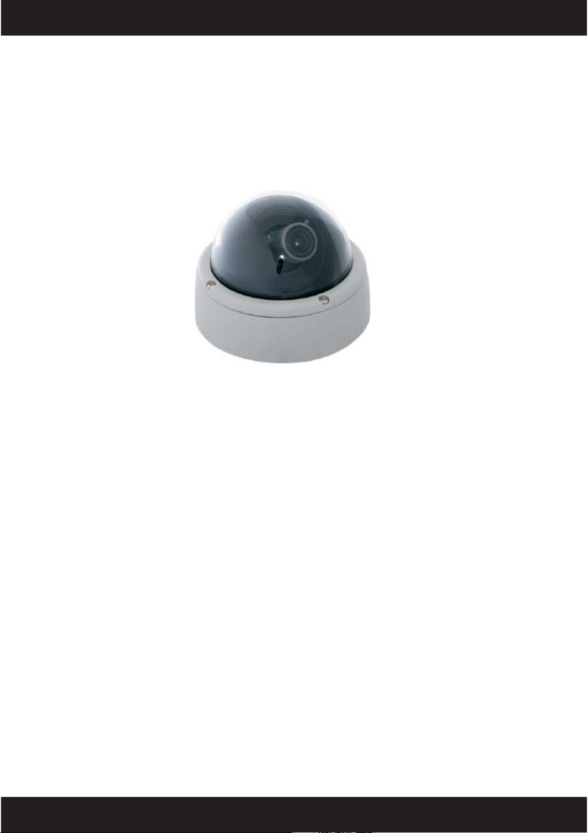
Internal Dome
Surface Mount
Cameras
Installation Manual
The information in this manual provides installation details for the following :-
15-CD35F
15-CD35VA Colour SONY Super HAD medium resolution 3.9-8.3mm lens, 12v
15-CD45F Colour SONY Super HAD HQ1 high resolution 3.6mm lens 12v-24v
15-CD45VA Colour SONY Super HAD HQ1 high resolution 3.7-12mm lens, 12v-24v
Colour SONY Super HAD medium resolution 3.6mm lens, 12v
15-CD45HVA Day/Night SONY Super HAD HQ1 high resolution 3.7-12mm lens, 12v-24v
1
Page 2
NOTE: This equipment has been tested and found to comply with the limits for a class A
digital device, pursuant to part 15 of the FCC Rules. These limits are designed to provide
reasonable protection against harmful interference when the equipment is operated in a
commercial environment. This equipment generates, uses, and can radiate radio
frequency energy and, if not installed and used in accordance with the instruction manual,
may cause harmful interference to radio communications. Operation of this equipment
in a residential area is likely to cause harmful interference in which case the user will be
required to correct the interference at his own expense.
Disposal of Old Electrical & Electronic Equipment (Applicable
in the European Union and other European countries with
separate collection systems)
This symbol on the product or on its packaging indicates that this product shall not be
treated as household waste. Instead it shall be handed over to the applicable collection
point for the recycling of electrical and electronic equipment. By ensuring this product
is disposed of correctly, you will help prevent potential negative consequences for the
environment and human health, which could otherwise be caused by inappropriate
waste handling of this product. The recycling of materials will help to conserve natural
resources. For more detailed information about recycling of this product, please
contact your local city of ce, your household waste disposal service or the shop where
you purchased the product.
Caution:
Read and follow all instructions carefully.
Do not operate the camera beyond the speci ed temperature or
power source ratings.
Refer all servicing to quali ed service personnel. Servicing is required
when the apparatus has been damaged in any way.
This unit contains semiconductor devices that can be damaged by
electrostatic discharge. Please take all necessary precautions during
installation to prevent electrostatic discharge.
This unit is designed for indoor use only. Do not use the unit in
locations where it is susceptible to rain or moisture.
2
Copyright © 2008 Cop Security Ltd. All rights reserved.
Product speci cations subject to change without notice.
Page 3
Features
High performance 1/3” SONY Super HAD CCD.
Camera Board mounted in 3-Axis Gimbal.
Surface mount.
Mirror picture function.
Moving IR cut lter. (15-CD45HVA).
Mini xed iris lens 3.6mm. (15-CD35F,15-CD45F)
Vari-focal iris 3.9~8.3mm lens. (15-CD35VA)
Vari-focal iris 3.7~12.0mm lens. (15-CD45VA, 15-CD45HVA)
Digital slow shutter. (DSS) (15-CD45F, 15-CD45VA,15-CD45HVA)
Power input :
- DC 12V (15-CD35F, 15-CD35VA)
- DC 12V / AC 24V (15-CD45F, 15-CD45VA, 15-CD45HVA)
INSTALLATION - using supplied cable
Please ensure the wall or ceiling on which the unit is to be mounted is of suitable strength
to support the weight of the unit.
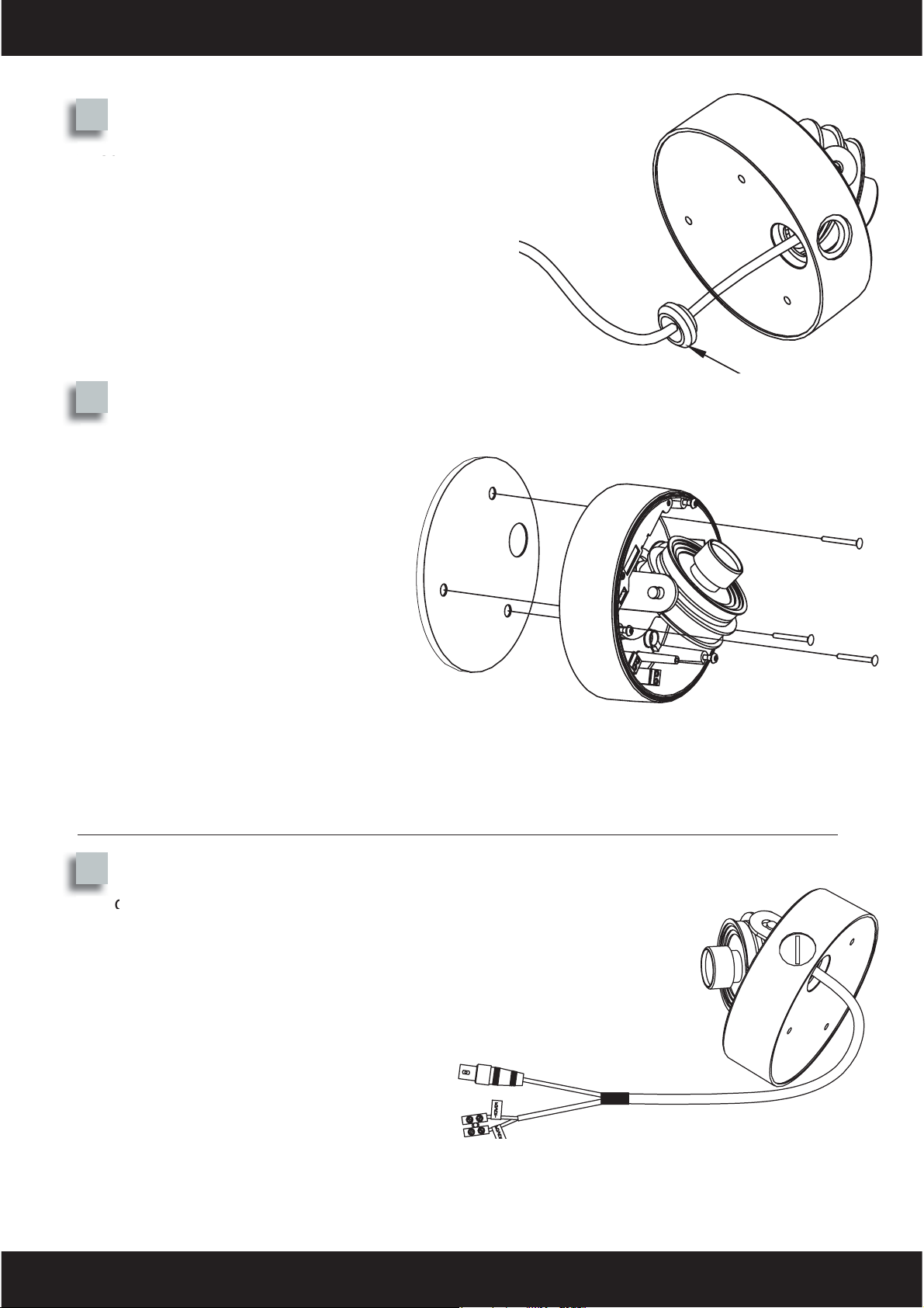
1
Loosen the three security screws on the
cover of the dome housing using the Allen
key provided.
2
Stick the drilling guide template provided
to the wall or ceiling where the camera is to
be sited.
Drill three holes for the plastic “wall plugs”
then insert the wall plugs.
Drill the hole for the cable entry.
3
Page 4
3
A
Ensure the the rubber grommet is seated
correctly in the base of the dome and around
the cable to help prevent the ingress of dust or
moisture.
4
A rubber gasket is supplied to be
tted between the base of the dome
camera and the mounting surface.
Peel the protective backing off the
gasket then, carefully aligning the
xing and cable entry holes, stick
the gasket to the base of the dome.
Feed the power and video
connections through the gasket
and the wall/ceiling then secure the
camera in place using the screws
provided or other suitable hardware.
Gasket
Connections - using supplied cable
Grommet
5
The camera is provided with a screwed
terminal block or DC Jack on a ying
lead for the power supply connections.
If a dc supply is used this must be
regulated.
The camera comes with a ying lead for
video out.
The video out lead is terminated into
a male BNC connector allowing the
installer to connect the camera to a
DVR/monitor/mux etc. using a female
BNC-BNC lead.
4
Page 5

Use only Class 2 indoor/dry or Class 3 outdoor/wet power supplies. (depending on the
installation environment).
Since the PSU supplying the camera will be running continuously, it is recommended to use
a PSU that is rated to supply at least 25% higher than the maximum current required by the
camera. (see Speci cations at the back of this manual for individual camera requirements).
12Vdc Connection.
The terminal block is clearly marked for +ve and -ve connections. Please observe polarity
when making dc connections.
The DC Jack accepts 2.1mm DC power plugs with centre pin positive.
24Vac Connection.
Since the power is 24V AC (alternating current), the connections to the terminal block can
be made either way round.
When the xings and connections have been made, the camera functions
need to be set-up to complete the installation. (see page 8)
INSTALLATION - wiring directly to the camera
Please ensure the wall or ceiling on which the unit is to be mounted is of suitable strength
to support the weight of the unit.
1
Loosen the three security screws on the
cover of the dome housing using the Allen
key provided.
2
Stick the drilling guide template provided
to the wall or ceiling where the camera is to
be sited.
Drill three holes for the plastic “wall plugs”
then insert the wall plugs.
Drill the hole for the cable entry.
5
Page 6

3
Carefully unplug the connector of the existing
cable as shown.
Remove the cable and grommet from the
camera.
4
Install the rubber grommet and make a small
hole in the grommet to feed the cable through
Ensure the grommet is seated correctly in the
base of the dome to help prevent the ingress
of dust or moisture.
Unplug
connector
5
A rubber gasket is supplied to be
tted between the base of the dome
camera and the mounting surface.
Peel the protective backing off the
gasket then, carefully aligning the
xing and cable entry holes, stick
the gasket to the base of the dome.
Feed the power and video
connections through the rubber
cable entry grommet.
Secure the camera in place using
the screws provided or other
suitable hardware.
Grommet
Gasket
6
Page 7

Connections
+P-P
POWER
(Orange)
VIDEO
(Green)
6
The camera is provided with two
2way Plug-on screwed terminal
blocks.
A 2way block for the Power
connection. (Orange).
A 2way block for the video
connection. (Green).
Use only Class 2 indoor/dry or Class 3 outdoor/wet power supplies. (depending on the
installation environment)
Since the PSU supplying the camera will be running continuously, it is recommended to use
a PSU that is rated to supply at least 25% higher than the maximum current required by the
camera. (see Speci cations at the back of this manual for individual camera requirements).
V+ V-
12Vdc Connection.
If a dc supply is used this must be regulated.
The terminal block is clearly marked for the 12v positive (P+) and 0v (P-) connections.
Please observe polarity when making dc connections.
24Vac Connection.
Since the power is 24V AC (alternating current), the connections to the terminal block can
be made either way round.
Video Connection.
It is recommended you use an RG59 or twisted pair cable to bring the video signal back
from the camera to the DVR/monitor/mux etc.
The Video out from the camera requires two connections.
When using a coax cable such as RG59, the inner core provides the “Video” connection
(V+) and the outer braid of the coax is used for the 0V GROUND (V-) connection.
When the xings and connections have been made, the camera functions
need to be set-up to complete the installation. (see page 8)
7
Page 8

Camera Set-up
The camera position can be adjusted in three axis
- Pan (horizontal) Tilt (vertical) and Rotate.
Pan and tilt the camera/lens assembly to
obtain the desired picture.
Do not hold the lens when moving the camera/lens
assembly.
The picture can be “squared up” by rotating the
camera about its own axis.
Remove the transit packaging to access and
loosen the locking screw to allow camera rotation.
Remember to tighten the screw when the desired
picture has been achieved.
Lens Adjustment
To adjust the lens, to suit your particular
application, loosen off the locking screws then alter
the focus (between Near and in nity) and the Field
of View angle (between Telephoto and Wide)
Transit
packaging
Loosen to
adjust Field
of View
When the adjustments have been made and the
desired picture has been achieved, tighten the
locking screws to secure your settings.
Camera Functions
To set the camera for optimum
performance there are a number
of options you can select to suit
different applications.
DC Level Adjust
Loosen to
adjust Focus
Function switches
8
Page 9

Function Switch Settings
15-CD35F | 15-CD35VA 15-CD45F | 15-CD45VA | 15-CD45HVA
12
AGC
ATW
AWB
3456
OFF
OFF
BLC
MIR
OFF
132
ALC ELC
AGC
OFF
ATW
AWB
BLC
OFF
645 7
D/N
OFF
MIR
DAY
DSS
OFF
AWB / ATW
The camera has two settings, AWB (Auto White Balance) and ATW (Auto Tracing White
balance) ABW will set white objects white according to the colour temperature at the time.
ATW automatically tries to keep white objects as white even if the colour temperature of the
light changes. For most applications, ATW is the recommended setting.
AGC (Automatic Gain Control)
When AGC is selected, this increases the amount of ampli cation applied to the video
signal to allow the signal to maintain a constant level in low light conditions.
MIR (Mirror)
The image viewed can be set to display as a mirrored image (horizontally ipped) when
output to the DVR, monitor, mux etc.
BLC (Back Light Compensation)
When BLC is selected, the camera tries to compensate for the bright part of an image, e.g.
an outside widow, so that the surrounding area is not too dark.
ELC / ALC
The ELC/ALC switch is used to select Electronic Light Compensation or Automatic Light
Compensation. ELC is used for external auto iris lenses. ALC is used for internal auto iris
lenses.
DAY / D/N
The day/night dome cameras include a switch to select having the day/night feature turned
on or off.
If D/N is selected, the camera changes to monochrome mode during low light conditions
and the resolution and sensitivity increase.
DSS (Digital Slow Shutter)
With DSS selected the camera has a longer exposure time, enabling the camera to operate
in minimal light conditions.
DC Level Adjust
The potentiometer next to the DIP switches is used to adjust the DC level for autoiris.
Use a small screwdriver to open and close the iris to regulate the light extremes.
Turning clockwise opens the iris wider, allowing in more light.
9
Page 10

Completion
When the camera is installed and set-up as
required, re- t the dome cover to the camera
base and secure with the three screws using
the Allen key provided.
Trouble Shooting
No Picture:
- Check the supply voltage to the camera.
- Check the BNC video lead connection. The centre core carries the video signal
and the outer core or screen is the ‘video signal return’
Picture too bright or dark:
- The ALC control is not set correctly
- The BLC switch needs setting
Poor Night Time Pictures:
- Check the dip switch con guration, if the camera is supplied with an auto iris
lens as standard then this should be set for ALC (Auto Iris) and not ELC
(Electronic Iris).
- Check the dip switch con guration that D/N has been selected.
- Check the setup of the camera in its brightest operating conditions and adjust
the DC level control as described in the instructions.
- Select DSS to allow the camera more exposure time.
- Check there is suf cient lighting available for the area being viewed.
Poor Focus:
- Check the lens adjustments for focus.
- Check the DC level control. This controls the iris aperture and if it is open too
much then the picture will not be sharp.
- Check that the dome cover is clean.
To clean the cover, use a soft dry cloth. Do not use caustic or abrasive cleaners
that may scratch the surface.
10
Page 11

Speci cations
15-CD35F 15-CD35VA
Type COLOUR
Pick Up Device 1/3” SONY CCD Image Sensor
Picture Elements NTSC: 537H x 505V PAL: 537H x 597V
Horizontal Resolution 420 TV Lines
Mini Illumination 0.5Lux
Vertical Frequency NTSC: 60 Hz PAL: 50 Hz
Scanning System 2:1 INTERLACE
S/N Ratio 48 dB
Electronic Shutter AI NTSC:1/60sec PAL:1/50sec
AES NTSC:1/60~1/100,000 sec PAL:1/50~1/100,000 sec
Lens 3.6 mm 3.9 ~ 8.3mm
White Balance AUTO
Back Light Compensation ON/OFF
Auto Gain Control AUTO
Gamma. 0.45
Video Output 1.0 Vp-p composite video at 75 ohm
Power Supply DC12V
Power Consumption 130 mA
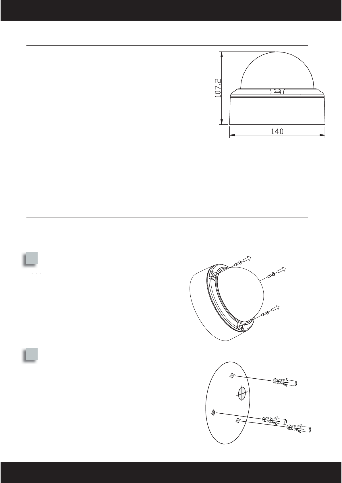
Dimensions D x H mm 140 X 107.2
Weight 455 g 480 g
Storage Temperature –30 ~ +60 Degrees C
Operating Temperature –10~ +45 Degrees C
15-CD45F 15-CD45VA 15-CD45HVA
Type COLOUR COLOUR/Monochrome
Pick Up Device 1/3” SONY SUPER HAD CCD Image Sensor
Picture Elements NTSC: 768H x 494V PAL: 752H x 582V
Horizontal Resolution 550 TV Lines
Mini Illumination 0.15Lux 0.001Lux
Vertical Frequency NTSC: 60 Hz PAL: 50 Hz
Scanning System 2:1 INTERLACE
S/N Ratio 50 dB
Electronic Shutter AI NTSC:1/60sec PAL:1/50sec
AES NTSC:1/60~1/100,000 sec PAL:1/50~1/100,000 sec
Lens 3.6 mm 3.7~12mm 3.7~12mm IR CUT
White Balance ATW/AWB
Back Light Compensation ON/OFF
Auto Gain Control ON/OFF
Gamma 0.45
Video Output 1.0 Vp-p composite video at 75 ohm
Power Supply DC12V /AC24V
Power Consumption 150 mA/(12vdc) 60mA(24vac) 180 mA(12vdc) 60mA(24vac)
Dimensions D x H mm 140 X 107.2
Weight g. 455 g 480 g
Storage Temperature –30 ~ +60 Degrees C
Operating Temperature –10 ~ +45 Degrees C
11
Page 12

12
 Loading...