

Page 1
15-CA25D / 15-CA25DNV
INSTRUCTION MANUAL
Page 2

OVERVIEW
The CA25D/CA25DNV are medium resolution colour camera. Both
cameras built in an advanced DNR system (Digital Noise Reduction).
DNR can significantly reduce the image noise under low light
conditions. Especially with the Auto Gain Control switched on (AGC
on).
FEATURES
• 1/3” SONY SUPER HAD CCD
• LOW POWER CONSUMPTION
• DUAL POWER SUPPLY (12vDC or 24vAC)
• HI SENSITIVITY
• HI SPEED WHITE BALANCE MODE
• BUILT-IN DSS-DIGITAL SLOW SHUTTER FUNCTION
• BUILT-IN DNR-DIGITAL NOISE REDUCTION FUNCTION
• TWISTED PAIR INTERFACE
• C/CS LENS MOUNT-BACK FOCUS ADJUSTABLE
Page 3

PRECAUTION
Do not open or modify
Do not adjust or modify the camera’s internal circuits or power supply
modules, as it may be dangerous and cause damage to the unit. For
internal settings and repairs, consult our dealer.
Do not put objects inside the unit
Make sure that no metal objects or flammable substance get inside
the camera that may cause damage to the unit. If water or a liquid get
inside the camera, disconnect the power cable immediately, and
consult your dealer. Be careful to protect the camera from direct
exposure to weather, rain, etc.
Be careful when handling the unit
Do not drop the camera or subject it to strong shock or vibration.
Install away from electric or magnetic fields
It may interfere with or distort the image when install close to an electric
or magnetic fields. Ex: TV, Speaker, etc.
Protect from humidity, dust and high temperatures
Do not install it where there is greasy smoke or steam, where the moisture may
get too high, or where there is a lot of dust...
Do not install close to stoves, or other heat generating devices, such
as spotlights, etc….
Avoid places where there is direct sunlight.
Cleaning
Do not directly touch the CCD element. If necessary, use a soft cloth
moistened with alcohol to wipe off any dust.
Page 4
INSTALLATION
Auto Iris Lens
1. Remove the protective cap from the camera’s lens mount.
2. Carefully align the CS/C lens into the camera lens mount and turn
clockwise slowly until it is firmly attached.
3. Insert the cable Plug into the lens terminal socket located behind
of the camera body.
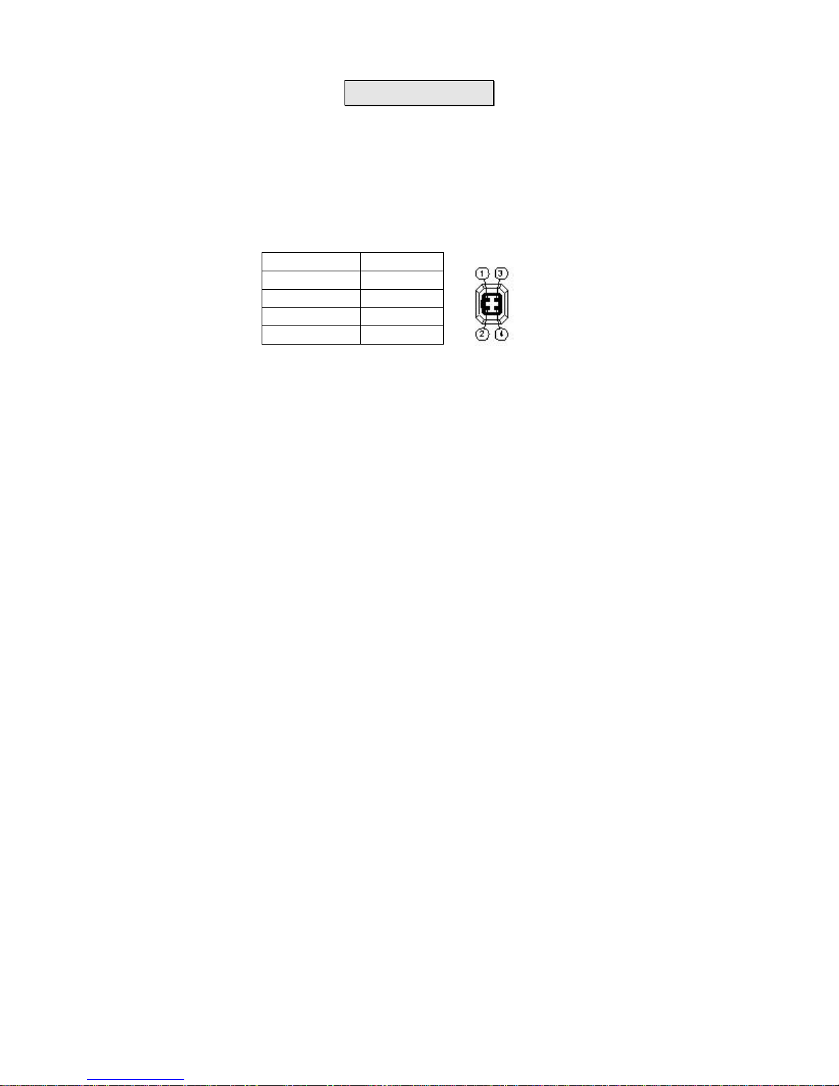
4. For IRIS connector details see the following table
Manual Iris Lens
1. Remove the protective cap from the camera’s lens mount.
2. Carefully align the CS/C lens into the camera lens mount and turn
clockwise slowly until it is firmly attached.
POWER SUPPLY
1. Before turning on the power to the camera, ensure that the lens is
fitted onto the camera to avoid damage to the exposed CCD
chipset.
2. You can use a DC12V or AC24V power supply for the camera.
CONNECTION
1. Connect the video and Audio outputs of the camera to the video /
Audio inputs of a monitor or DVR.
2. Connect power supply to the power input on the camera then turn
on the power.
3. Adjust the lens and camera’s setting to get the best image.
IRIS JACK DC-LENS
P1 DUMPP2 DUMP+
P3 DRIVE+
P4 DRIVE-
Page 5

DIMENTION & FUNCTION CONNECTOR
1. Auto iris lens connector (4-pin type)
The lens connector supplies the auto-iris lens (not supplied) with
DC power and DC control signal.
2.DIP switch function
Page 6

Sw1 . BLC (Back light compensation) mode switch:
When strong light is present behind the object being viewed, the
object will appear dark. In this case, put this switch in the BLC
position.
Sw2. AI/AE switch:
AE (Auto Electronic Shutter) For fixed or manual Iris lens
AI (Auto Iris) For auto Iris lens.
Sw3. AT W / AWB switch
The ATW mode automatically adjusts white balance according to
changes in lighting conditions (2,500K to 10,000K).
The AWB mode automatically or manually adjusts and locks the
white balance for specific lighting conditions.
Sw4. AGC switch
The AGC function adjusts the image sensor gain and will
enhance the low light capability of the camera, however under
extremely low light conditions the picture may become noisy.
Sw5. DSS switch
The DSS function allows the camera to use a slow shutter speed
in extremely low light conditions, this will enhance the low light
capability but fast moving objects may appear blurred in low light.
Sw6. H-Mir switch
The horizontal mirror function reverses the image creating a
mirror image.
3. Level
This is used to adjust video output level of DC driven auto iris
lens.
4. Power input
Connect the power supply of 24Vac or 12Vdc
5. Power input indicate
The led will light when power input.
6. Video output
Page 7

This is the standard video output for connecting to a video
monitor, etc (75Ω).
7. Audio output
It is an output for connecting to audio equipment.
SPECIFICATION
MODEL 15-CA25D 15-CA25DNV
SENSOR / DSP 1/3 “ SONY SUPER HAD CCD
NUMBER of PIXELS NTSC:512x492 PAL:512x582
SCANNING 2:1 INTERLACE
SYNCHRONISATION INTERNAL
HORIZONTAL FREQUENCY NTSC:15.734 kHz PAL:15.625 kHz
VERTICAL FREQUENCY NTSC:59.94 Hz PAL:50 Hz
RESOLUTION 420 TV LINES
VIDEO OUT LEVEL 1.0Vp-p/75Ω VIDEO 0.714Vp-p Sync 0.286Vp-p
BURST Sync 0.286Vp-p
S/N
50dBMin.(γ,Aperture, AGC Correct OFF)
MINIMUM ILLUMINATION 1Lux/0.005Lux (DSS ON) 0.05Lux/0.005Lux (DSS ON)
Y CORRECTION 0.45
AGC +18dB Max.
IRIS CONTROL ELECTRICAL IRIS/Auto IRIS (DC LENS CONTROL)
ELECTRICAL SHUTTER 1/60(1/50)~1/120000 sec.
POWER SUPPLY VOLTAGE DC12V / AC24V
POWER SUPPLY CURRENT 150mA Max. (DC12V) / 60mA Max. (AC24V)
DIMENSION 58(W) X 62H X 118(L) mm
STORAGE TEMP.
-30℃~60℃
OPERATING TEMP.
-10℃~45℃
THIS DEVICE COMPLIES WITH PART 15 OF THE FCC RULES.
OPERATI ONS I S SUBJECT TO THE FOLLOWI NG TWO
CONDI T I ONS :(1 ) THI S DE VI CE MAY NOT C AUSE HARMFUL
I NT ERF ERE NCE AND ( 2 ) THI S DE VI CE MUST ACCE PT ANY
I NTE RF ER ENC E REC EI VE D. I NCL UDI NG I NT ER FE RENCE
THAT MAY CAUSE UNDESIRABLE OPERATION. .
 Loading...