

Page 1
Xenus XTL™ User Guide
P/N 95-00875-000
Revision 3
June 2008
Page 2

Xenus XTL User Guide
This page for notes.
Page 3

TABLE OF CONTENTS
About This Manual ................................................................................................................................................................................5
1: Introduction ................................................................................................................................................................................. 9
1.1: Amplifier ............................................................................................................................................................................... 10
1.2: CME 2 .................................................................................................................................................................................. 11
1.3: CMO/CML ............................................................................................................................................................................11
2: Operational Theory....................................................................................................................................................................13
2.1: Amplifier Internal Power........................................................................................................................................................ 14
2.2: Synchronizing PWM Switching Frequency............................................................................................................................ 16
2.3: Commutation Modes ............................................................................................................................................................ 16
2.4: Feedback.............................................................................................................................................................................. 16
2.5: Operating Modes.................................................................................................................................................................. 17
2.6: CANopen Operation .............................................................................................................................................................28
2.7: Limit Switches ...................................................................................................................................................................... 30
2.8: Brake Operation ................................................................................................................................................................... 31
2.9: Status Indicators................................................................................................................................................................... 32
2.10: Protection...........................................................................................................................................................................34
2.11: Position and Velocity Errors................................................................................................................................................ 36
2.12: Communication ..................................................................................................................................................................39
2.13: Inputs .................................................................................................................................................................................40
2.14: Outputs............................................................................................................................................................................... 41
2.15: Regen Resistor Theory....................................................................................................................................................... 42
3: Specifications............................................................................................................................................................................ 43
3.1: Agency Approvals.................................................................................................................................................................44
3.2: Power Input ..........................................................................................................................................................................44
3.3: Power Output........................................................................................................................................................................ 44
3.4: Control Loops ....................................................................................................................................................................... 45
3.5: Regen Circuit Output ............................................................................................................................................................ 45
3.6: Digital Command Input ......................................................................................................................................................... 45
3.7: Analog Command Input........................................................................................................................................................46
3.8: Digital Inputs.........................................................................................................................................................................46
3.9: Digital Outputs......................................................................................................................................................................46
3.10: Brake Output ...................................................................................................................................................................... 47
3.11: Encoder Power Supply Output............................................................................................................................................ 47
3.12: Primary Encoder Inputs ...................................................................................................................................................... 47
3.13: Analog Encoder Inputs .......................................................................................................................................................47
3.14: Hall Switch Inputs...............................................................................................................................................................48
3.15: Resolver Interface .............................................................................................................................................................. 48
3.16: Multi-Mode Port .................................................................................................................................................................. 48
3.17: Serial Interface ................................................................................................................................................................... 49
3.18: CAN Interface.....................................................................................................................................................................49
3.19: Status Indicators................................................................................................................................................................. 49
3.20: Fault Levels ........................................................................................................................................................................ 49
3.21: Power Dissipation............................................................................................................................................................... 50
3.22: Thermal Impedance............................................................................................................................................................50
3.23: Mechanical and Environmental...........................................................................................................................................50
3.24: Dimensions......................................................................................................................................................................... 51
4: Wiring......................................................................................................................................................................................... 53
4.1: General Wiring Instructions ..................................................................................................................................................54
4.2: AC Mains (J1)....................................................................................................................................................................... 56
4.3: Motor (J2) ............................................................................................................................................................................. 57
4.4: Regen Resistor (J3) (Optional) .............................................................................................................................................59
4.5: Logic Supply / Brake (J4)...................................................................................................................................................... 60
4.6: RS-232 Serial Communications (J5)..................................................................................................................................... 61
4.7: CAN Bus (J6) ....................................................................................................................................................................... 62
4.8: Control (J7)........................................................................................................................................................................... 63
4.9: Motor Feedback (J8)............................................................................................................................................................. 67
5: Quick Setup with CME 2 ........................................................................................................................................................... 73
5.1: Warnings..............................................................................................................................................................................74
5.2: CME 2 Installation and Serial Port Setup.............................................................................................................................. 75
5.3: Prerequisites ........................................................................................................................................................................ 79
5.4: Basic Setup..........................................................................................................................................................................81
5.5: Motor/Feedback Setup .........................................................................................................................................................84
5.6: Amplifier Configuration .........................................................................................................................................................93
5.7: Command Input.................................................................................................................................................................. 103
5.8: Auto Phase.........................................................................................................................................................................110
5.9: Current Loop....................................................................................................................................................................... 116
5.10: Velocity Loop....................................................................................................................................................................120
5.11: Position Loop.................................................................................................................................................................... 122
5.12: Completion Steps .............................................................................................................................................................126
6: Using CME 2 ............................................................................................................................................................................ 127
Copley Controls Corp. 3
Page 4

Table of Contents Xenus XTL User Guide
6.1: CME 2 Overview.................................................................................................................................................................128
6.2: Manage Amplifier and Motor Data ...................................................................................................................................... 133
6.3: Downloading Firmware .......................................................................................................................................................136
6.4: Control Panel...................................................................................................................................................................... 138
6.5: Manual Phasing.................................................................................................................................................................. 142
6.6: Home Function................................................................................................................................................................... 144
A: Regen Resistor Sizing and Configuration ............................................................................................................................. 145
A.1: Sizing a Regen Resistor..................................................................................................................................................... 146
A.2: Configuring a Custom Regen Resistor ............................................................................................................................... 150
B: I2T Time Limit Algorithm ......................................................................................................................................................... 153
B.1: I2T Algorithm ...................................................................................................................................................................... 154
C: Thermal Considerations.......................................................................................................................................................... 159
C.1: Operating Temperature and Cooling Configurations .......................................................................................................... 160
C.2: Heatsink Mounting Instructions .......................................................................................................................................... 162
D: Xenus Filter.............................................................................................................................................................................. 163
D.1: Overview............................................................................................................................................................................164
D.2: XTL-FA-01 Edge Filter Specifications ................................................................................................................................ 165
D.3: Thermal Considerations..................................................................................................................................................... 165
D.4: XTL-FA-01 Edge Filter Dimensions.................................................................................................................................... 166
D.5: XTL-FA-01 Edge Filter Wiring............................................................................................................................................ 167
D.6: XTL-FA-01 Edge Filter Ordering.........................................................................................................................................171
E: Connecting for Serial Control................................................................................................................................................. 173
E.1: Single-Axis and Multi-Drop ................................................................................................................................................. 174
F: Ordering Guide and Accessories ........................................................................................................................................... 175
F.1: Amplifier Model Numbers ................................................................................................................................................... 176
F.2: Accessory Model Numbers.................................................................................................................................................177
F.3: Order Example ................................................................................................................................................................... 178
F.5: Copley Standard Regen Resistor Specifications................................................................................................................. 179
4 Copley Controls Corp.
Page 5

ABOUT THIS MANUAL
Overview and Scope
This manual describes the operation and installation of the Xenus XTL amplifier manufactured by
Copley Controls Corporation.
Related Documentation
For important setup and operation information, see the CME 2 User Guide.
Users of the CANopen features should also read these Copley Controls documents:
• CANopen Programmer’s Manual
• CML Reference Manual
• Copley Motion Objects Programmer’s Guide
Also of related interest:
• Copley Indexer 2 Program User’s Guide (describes use of Indexer Program to create motion
control sequences)
• Copley Controls ASCII Interface Programmer’s Guide (describes how to send ASCII format
commands over an amplifier’s serial bus to set up and control one or more amplifiers)
• Copley Amplifier Parameter Dictionary
• Copley Camming User Guide
• Copley DeviceNet Programmer’s Guide
Information on Copley Controls Software can be found at:
http://www.copleycontrols.com/Motion/Products/Software/index.html
Comments
Copley Controls Corporation welcomes your comments on this manual.
For contact information, see http://www.copleycontrols.com
Copyrights
No part of this document may be reproduced in any form or by any means, electronic or
mechanical, including photocopying, without express written permission of Copley Controls
Corporation.
Xenus and XTL are registered trademarks of Copley Controls Corporation.
CME 2 is a registered trademark of Copley Controls Corporation.
Windows NT, ME, 2000, XP, Vista, Visual Basic, Excel, and .NET are trademarks or registered
trademarks of the Microsoft Corporation.
LabVIEW is a registered trademark of National Instruments.
Document Validity
We reserve the right to modify our products. The information in this document is subject to change
without notice and does not represent a commitment by Copley Controls Corporation. Copley
Controls Corporation assumes no responsibility for any errors that may appear in this document.
Copley Controls Corp. 5
Page 6

About this Manual Xenus XTL User Guide
Product Warnings
Observe all relevant state, regional, and local safety regulations when installing and using this
product. For safety and to assure compliance with documented system data, only Copley Controls
Corporation should perform repairs to amplifiers.
DANGER: Hazardous voltages.
Exercise caution when installing and adjusting.
!
DANGER
!
DANGER
!
DANGER
Failure to heed this warning can cause equipment damage, injury, or death.
Risk of electric shock.
High-voltage circuits on J1, J2, and J3 are connected to mains power.
Failure to heed this warning can cause equipment damage, injury, or death.
Risk of unexpected motion with non-latched faults.
After the cause of a non-latched fault is corrected, the amplifier re-enables the PWM
output stage without operator intervention. In this case, motion may re-start
unexpectedly. Configure faults as latched unless a specific situation calls for nonlatched behavior. When using non-latched faults, be sure to safeguard against
unexpected motion.
Failure to heed this warning can cause equipment damage, injury, or death.
Using CME 2 or serial commands may affect or suspend CAN operations.
When operating the amplifier as a CAN node, the use of CME 2 or ASCII serial
!
DANGER
!
DANGER
!
DANGER
commands may affect CAN operations in progress. Using such commands to initiate
motion may cause CAN operations to suspend.
CAN operations may restart unexpectedly when the commanded motion is stopped.
Failure to heed this warning can cause equipment damage, injury, or death.
Latching an output does not eliminate the risk of unexpected motion with nonlatched faults.
Associating a fault with a latched, custom-configured output does not latch the fault
itself. After the cause of a non-latched fault is corrected, the amplifier re-enables
without operator intervention. In this case, motion may re-start unexpectedly.
For more information, see Clearing Non-Latched Faults (p. 34).
Failure to heed this warning can cause equipment damage, injury, or death.
Use equipment as described.
Operate amplifiers within the specifications provided in this manual.
Failure to heed this warning can cause equipment damage, injury, or death.
6 Copley Controls Corp.
Page 7

Xenus XTL User Guide About this Manual
Revision History
Revision Date DECO# Comments
1 December 2007 16236 Initial release.
2 February 2008 16714 Updated Multi-Mode Port Interface Diagram (p. 66).
3 June 2008 17111 Updated Web page references and made other minor changes.
Copley Controls Corp. 7
Page 8

About this Manual Xenus XTL User Guide
This page for notes.
8 Copley Controls Corp.
Page 9

CHAPTER
1: INTRODUCTION
This chapter provides an overview of the Copley Controls Xenus XTL amplifier.
Contents include:
Title Page
1.1: Amplifier ............................................................................................................................................................................... 10
1.2: CME 2 .................................................................................................................................................................................. 11
1.3: CMO/CML ............................................................................................................................................................................11
Copley Controls Corp. 9
Page 10

Introduction Xenus XTL User Guide
1.1: Amplifier
Xenus provides 100% digital control of brushless or brush motors in an off-line powered package.
It can also control a Copley Controls ServoTube motor. Xenus can operate from single or threephase mains with a continuous power output of up to 4 kW.
Xenus is offered in three versions to support three types of feedback devices. The standard
version supports digital quadrature encoders. The –S version supports analog sin/cos encoders.
The -R version supports brushless resolvers. The –S and -R versions can emulate a digital
quadrature encoder output from the analog encoder or resolver respectively.
Xenus can operate in several basic ways:
• As a traditional motor amplifier accepting current, velocity or position commands from an
external controller. In current and velocity modes it can accept ±10 Vdc analog, digital 50%
PWM or PWM/polarity inputs. In position mode, inputs can be incremental position commands
from step-motor controllers in Pulse and Direction or Count Up/Count Down format, as well as
A/B quadrature commands from a master-encoder. Pulse-to-position ratio is programmable for
electronic gearing.
• As a node on a CANopen network. CANopen compliance allows the amplifier to take
instruction from a master application over a CAN network to perform torque, velocity, and
position profiling, interpolated motion, and homing operations. Multiple drives can be tightly
synchronized for high performance coordinated motion.
• As a node on a DeviceNet network. Xenus can be operated over a DeviceNet network by
PLCs and other controllers.
• As a stand-alone controller running Copley Virtual Machine (CVM) control programs such as
the Indexer 2 Program. It can also be controlled directly over an RS232 serial link with simple
ASCII format commands.
Mains input voltage to the amplifier can range from 100 to 240 Vac, single or three-phase, and 47
to 63 Hz. This allows Xenus the ability to work in the widest possible range of industrial settings.
Several models are available, with peak current ratings of 18 to 40 amps:
Model
Quad A/B
Encoder
XTL-230-18 XTL-230-18-R XTL-230-18-S 6 A 18 A
XTL-230-36 XTL-230-36-R XTL-230-36-S 12 A 36 A
XTL-230-40 XTL-230-40-R XTL-230-40-S 20 A 40 A
Resolver Sin/Cos Encoder Continuous
Current
Peak Current Vac
100 to
240
A separate +24 Vdc logic supply powers the internal logic and control circuits. These are isolated
from the high-voltage power supply and inverter stage that connect to the mains. This simplifies
system design by allowing the mains to be completely disconnected from the amplifier for safety
reasons while allowing the logic side of the amplifier to stay powered. This allows the amplifier to
retain position information and maintain communication through the digital I/O or over the serial or
CAN ports when disconnected from the mains.
The Xenus XTL is RoHS compliant.
10 Copley Controls Corp.
Page 11

Xenus XTL User Guide Introduction
1.2: CME 2
Amplifier commissioning is fast and simple using Copley Controls CME 2 software. CME 2
communicates with Xenus via an RS-232 link, and all of the operations needed to configure the
amplifier are accessible through CME 2.
The multi-drop feature allows CME 2 to use a single RS-232 serial connection to one amplifier as
a gateway to other amplifiers linked together by CAN bus connections.
Auto phasing of brushless motor Hall sensors and phase wires eliminates “wire and try.”
Connections are made once and CME 2 does the rest. Encoder or resolver wire swapping to
establish the direction of positive motion is also eliminated.
Motor data can be saved as .ccm files. Amplifier data is saved as .ccx files that contain all
amplifier settings plus motor data. This makes it possible to quickly set up amplifiers by copying
configurations from one amplifier to another.
1.3: CMO/CML
Copley Motion Libraries (CML) and Copley Motion Objects (CMO) make CANopen system
commissioning fast and simple. All network housekeeping is taken care of automatically by a few
simple commands linked into your application program. CML provides a suite of C++ libraries,
allowing a C++ application program to communicate with and control an amplifier over the
CANopen network. CMO provides a similar suite of COM objects that can be used by Visual
Basic, .NET, LabVIEW, or any other program supporting the Microsoft COM object interface.
Copley Controls Corp. 11
Page 12

Introduction Xenus XTL User Guide
12 Copley Controls Corp.
Page 13

CHAPTER
2: OPERATIONAL THEORY
This chapter describes the basics of Xenus operation. Contents include:
Title Page
2.1: Amplifier Internal Power........................................................................................................................................................ 14
2.2: Synchronizing PWM Switching Frequency............................................................................................................................ 16
2.3: Commutation Modes ............................................................................................................................................................ 16
2.4: Feedback.............................................................................................................................................................................. 16
2.5: Operating Modes.................................................................................................................................................................. 17
2.6: CANopen Operation .............................................................................................................................................................28
2.7: Limit Switches ...................................................................................................................................................................... 30
2.8: Brake Operation ................................................................................................................................................................... 31
2.9: Status Indicators................................................................................................................................................................... 32
2.10: Protection...........................................................................................................................................................................34
2.11: Position and Velocity Errors................................................................................................................................................ 36
2.12: Communication ..................................................................................................................................................................39
2.13: Inputs .................................................................................................................................................................................40
2.14: Outputs............................................................................................................................................................................... 41
2.15: Regen Resistor Theory....................................................................................................................................................... 42
Copley Controls Corp. 13
Page 14

Operational Theory Xenus XTL User Guide
2.1: Amplifier Internal Power
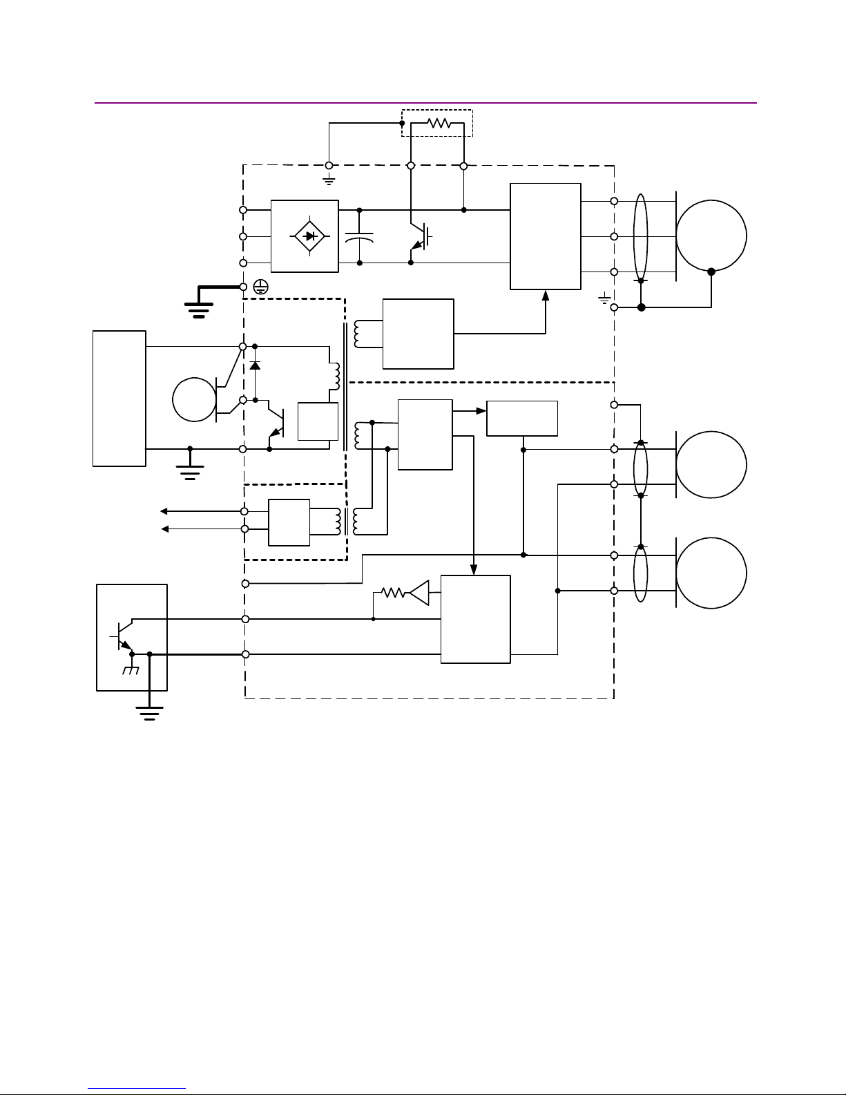
Power distribution within Xenus is divided into three sections: +24 Vdc, logic/signal, and high
voltage. Each is isolated from the other.
2.1.1: Logic/Signal Power
An internal DC/DC converter operates from the +24 Vdc Logic Supply input and creates the
required logic/signal operating voltages, the isolated voltages required for the high-voltage control
circuits, and a +5 Vdc supply for powering the motor encoder and Hall circuits. All the digital and
analog inputs, digital outputs (with the exception of OUT4), Hall and encoder inputs are referenced
to the same signal common. OUT4 is controlled through an opto-isolator, and is referenced to the
+24 Vdc return. The CAN interface is also optically isolated.
Deriving internal operating voltages from a separate source enables the amplifier to stay on-line
when the mains have been disconnected for emergency-stop or operator-intervention conditions.
This allows CAN bus and serial communications to remain active so that the amplifier can be
monitored by the control system while the mains power is removed.
2.1.2: High Voltage
Mains power drives the high-voltage section. It is rectified and capacitor-filtered to produce the DC
bus: the DC “link” power that drives the PWM inverter, where it is converted into the voltages that
drive a three-phase brushless or DC brush motor. An internal solid-state switch, together with an
external power resistor, provides dissipation during regeneration when the mechanical energy of
the motor is converted back into electrical energy. This prevents charging the internal capacitors
to an overvoltage condition.
14 Copley Controls Corp.
Page 15
Xenus XTL User Guide Operational Theory
2.1.3: Power and Grounding Diagram
SHIELD
AMPLIFIER
CHASSIS
REGEN(-)
REGEN(+)
FRAME
(SAFETY)
GROUND
+24
VDC
+24 Vdc
GROUND
CAN
Network
CONTROL
SYSTEM
MAINS
BRAKE
J1
J4
J6
L1
L2
L3
+24 Vdc
BRAKE
RTN
+5 Vdc
~
~
~
CAN
Bus
Ckt
DC/DC
Cntrl
DC/DC
Converter
+
-
1760 PF
+
J3
PWM
STAGE
CONTROL
POWER
LOGIC
&
SIGNAL
POWER
DC BUSS(+)
INVERTER
DC BUSS(-)
ISOLATION BARRIER
+5 Vdc @
400mA
PWM
SHIELD
+5 Vdc
SIGNAL GND
+5 Vdc
W
J2
U
V
MOTOR
CASE
HALLS
J8
ENCODER
J7
CONTROL
SIGNAL
GROUND
ENABLE [IN1]
SIGNAL GND
CONTROL
LOGIC
SIGNAL GND
Copley Controls Corp. 15
Page 16

Operational Theory Xenus XTL User Guide
2.2: Synchronizing PWM Switching Frequency
In some situations, such as when sampling small analog signals, it is desirable to synchronize the
PWM switching frequency among multiple amplifiers. In these cases, one amplifier serves as a
master for one or more slave amplifiers. The PWM sync output of the master sends a signal that
is received as a PWM sync input by each slave.
2.3: Commutation Modes
The amplifier supports three commutation modes to drive brush and brushless motors: AC
brushless sinusoidal, AC brushless trapezoidal, and DC brush.
In most applications, sinusoidal commutation is preferred over trapezoidal, because it reduces
torque ripple and offers the smoothest motion at any velocity or torque. In the sinusoidal
commutation mode, an encoder or a resolver are required for all modes of operation.
In AC brushless trapezoidal commutation mode, the amplifier provides traditional six-step
commutation.
When driving a DC brush motor, the amplifier operates as a traditional H-Bridge amplifier.
2.4: Feedback
2.4.1: Encoder and Resolver Support
The Xenus amplifier is offered in three versions to support encoder or resolver feedback. The
standard version supports digital quadrature encoders. The -S version supports analog sin/cos
encoders. These versions normally require the use of Hall switches for the commutation of
brushless motors. The resolver version supports standard, single speed, transmit-type resolvers.
2.4.2: Multi-Mode Port
All versions support a multi-mode port. This interface can be configured to:
• Provide a buffered digital encoder output based on the digital encoder input.
• Provide an emulated digital encoder output based on the analog encoder or resolver input.
• Provide a second digital encoder input to be used in the dual encoder position mode. In this
mode, an encoder attached to the load provides position loop feedback, and the motor
encoder or resolver provides velocity loop feedback.
16 Copley Controls Corp.
Page 17
Xenus XTL User Guide Operational Theory
2.5: Operating Modes
2.5.1: Modes and Control Loops
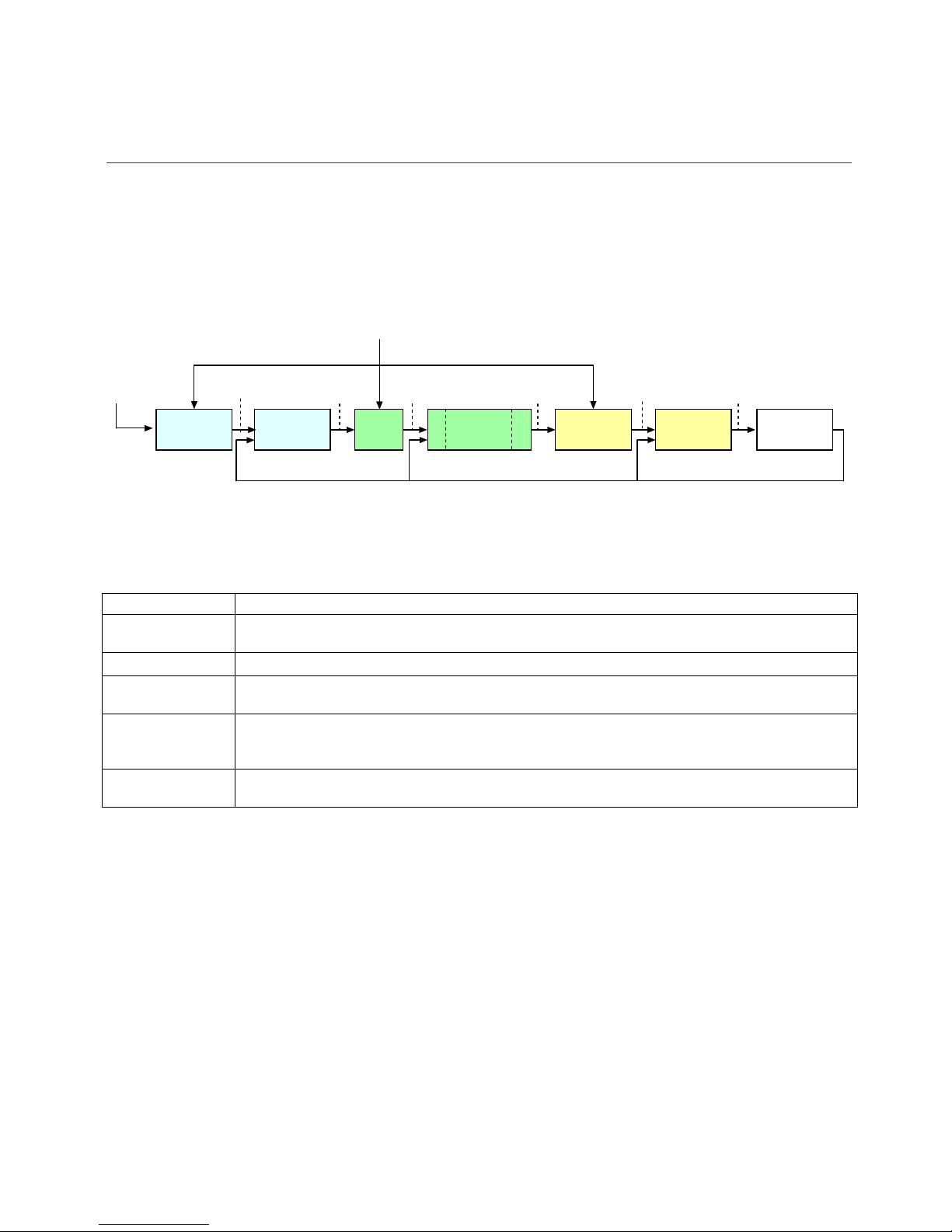
Nesting of Control Loops and Modes
Copley Controls amplifiers use up to three nested control loops - current, velocity, and position - to
control a motor in three associated operating modes.
Control Loops Illustration
In position mode, the amplifier uses all three loops. As shown below, the position loop drives the
nested velocity loop, which drives the nested current loop.
Limits
Target
Position
Trajectory
G
enerator
Position
Command
Position
L
oop
Ve loc ity
Command
Velocity
L
imiter
Limited
Velocity
Cur re nt
FILTER
Veloc ity
L
oop
Co mman d
FILTER
Cur re nt
L
Limited
Current
Current
imiter
Ac tual CurrentDerived VelocityActual Position
PWM
Command
L
oop
Motor/
S
ensors
In velocity mode, the velocity loop drives the current loop. In current mode, the current loop is
driven directly by external or internal current commands.
Basic Attributes of All Control Loops
These loops (and servo control loops in general) share several common attributes:
Loop Attribute Description
Command input Every loop is given a value to which it will attempt to control. For example, the velocity loop
receives a velocity command that is the desired motor speed.
Limits Limits are set on each loop to protect the motor and/or mechanical system.
Feedback The nature of servo control loops is that they receive feedback from the device they are
controlling. For example, the position loop uses the actual motor position as feedback.
Gains These are constant values that are used in the mathematical equation of the servo loop. The
values of these gains can be adjusted during amplifier setup to improve the loop
performance. Adjusting these values is often referred to as tuning the loop.
Output The loop generates a control signal. This signal can be used as the command signal to another
control loop or the input to a power amplifier.
Copley Controls Corp. 17
Page 18
Operational Theory Xenus XTL User Guide
2.5.2: Current Mode and Current Loop
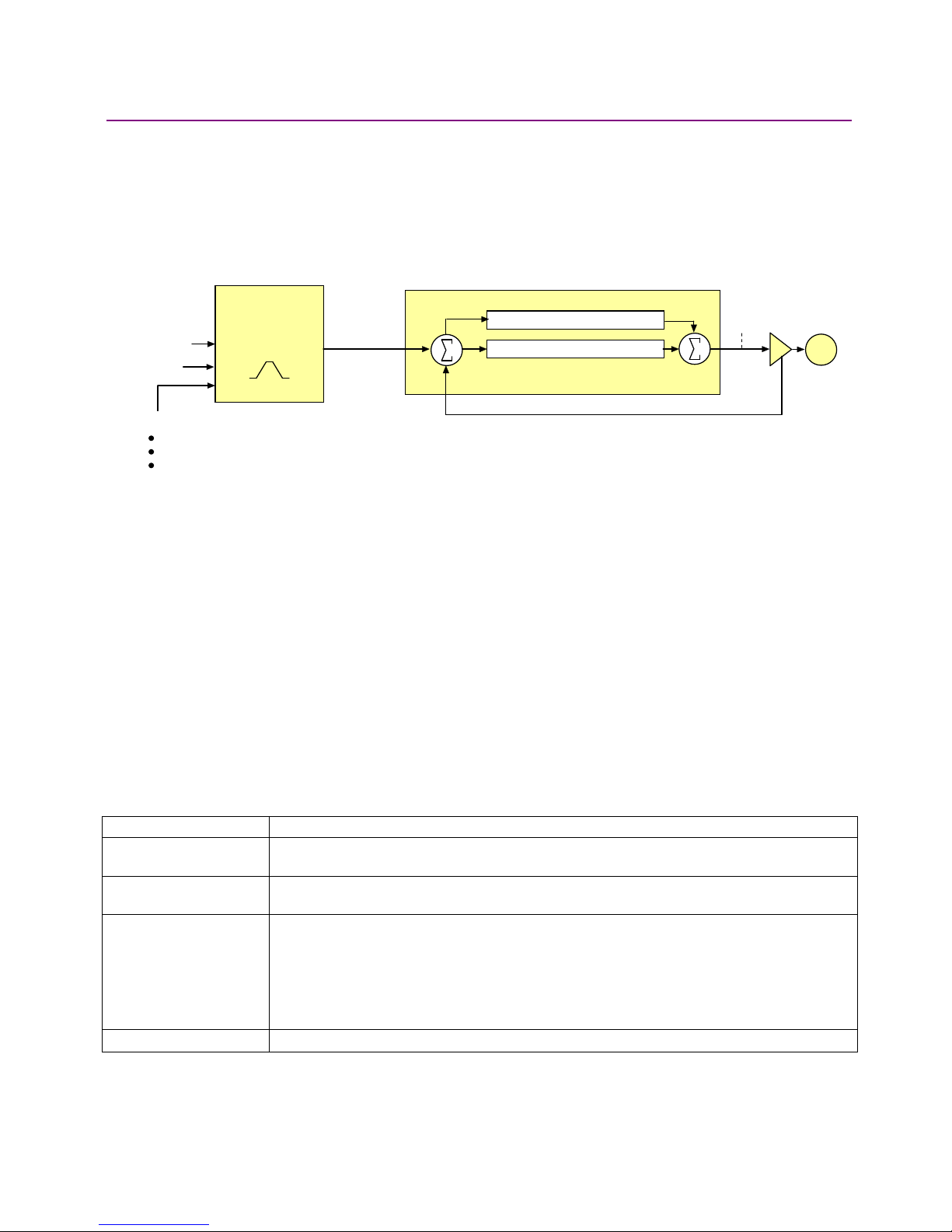
Current Loop Diagram
As shown below, the “front end” of the current loop is a limiting stage. The limiting stage accepts a
current command, applies limits, and passes a limited current command to the summing junction.
The summing junction takes the limited current command, subtracts the actual current
(represented by the feedback signal), and produces an error signal. This error signal is then
processed using the integral and proportional gains to produce a command. This command is
then applied to the amplifier’s power stage.
Current Command
Current Off set
Limits:
Peak Current
Continuous Current
Peak Curr ent Limit Time
Current Lim iter
Limited Current
Current Loop
Current Integral Gain (Ci)
+
-
Current Proportional Gain (Cp)
Feedback (A ctual Current)
+
+
PWM
Comman d
Mot or
Current Loop Inputs
• The amplifier’s analog or PWM inputs.
• A network command, CANopen, DeviceNet, or RS-232 Serial.
• A Copley Virtual Motion (CVM) control program.
• The amplifier’s internal function generator.
In velocity or position modes, the current command is generated by the velocity loop.
Offset
The current loop offset is intended for use in applications where there is a constant force applied
to, or required of, the servomotor and the system must control this force. Typical applications
would be a vertical axis holding against gravity, or web tensioning. This offset value is summed
with the current command before the limiting stage.
Limits
The current command is limited based on the following parameters:
Limiter Description
Peak Current Limit Maximum current that can be generated by the amplifier for a short duration of time. This
value cannot exceed the peak current rating of the amplifier.
Continuous Current
Limit
I2T Time Limit Maximum amount of time that the peak current can be applied to the motor before it must
Ramp Rate of change in current command.
18 Copley Controls Corp.
Maximum current that can be constantly generated by the amplifier.
be reduced to the continuous limit or generate a fault.
For more details, see I
Note: Although the current limits set by the user may exceed the amplifier's internal limits,
the amplifier operates using both sets of limits in parallel, and therefore will not exceed its
own internal limits regardless of the values programmed.
2
T Time Limit Algorithm (p. 153).
Page 19

Xenus XTL User Guide Operational Theory
Current Loop Gains
The current loop uses these gains:
Gain Description
Cp - Current loop proportional The current error (the difference between the actual and the limited commanded
current) is multiplied by this value. The primary effect of this gain is to increase
bandwidth (or decrease the step-response time) as the gain is increased.
Ci - Current loop integral The integral of the current error is multiplied by this value. Integral gain reduces the
current error to zero over time. It controls the DC accuracy of the loop, or the
flatness of the top of a square wave signal. The error integral is the accumulated
sum of the current error value over time.
Current Loop Output
The output of the current loop is a command that sets the duty cycle of the PWM output stage of
the amplifier.
Auto Tune
CME 2 provides a current loop Auto Tune feature, which automatically determines optimal Cp and
Ci values for the motor. For more information, see Auto Tune the Current Loop (p. 117).
Copley Controls Corp. 19
Page 20

Operational Theory Xenus XTL User Guide
2.5.3: Velocity Mode and Velocity Loop
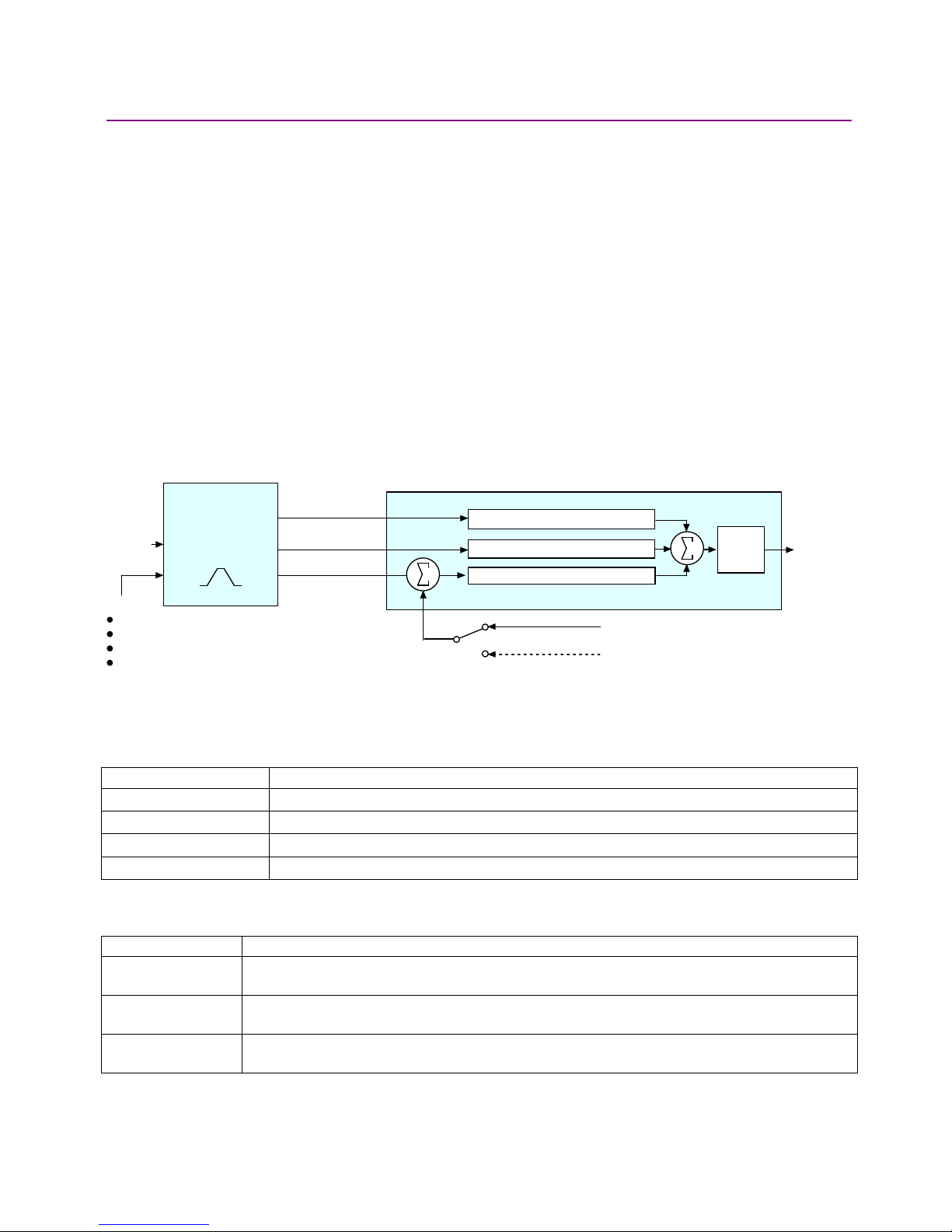
Velocity Loop Diagram
As shown below, the velocity loop limiting stage accepts a velocity command, applies limits, and
passes a limited velocity command to the input filter. The filter then passes a velocity command to
the summing junction. The summing junction subtracts the actual velocity, represented by the
feedback signal, and produces an error signal. (The velocity loop feedback signal is always from
the motor feedback device even when an additional encoder is attached to the load.) The error
signal is then processed using the integral and proportional gains to produce a current command.
Programmable digital filters are provided on both the input and output command signals.
Velocity Loop
Velocity
C
ommand
Limits:
*Not used w hen velocity loop is c ontrolled by position loop. See "V elocity Loop Limits" f or details.
Ve lo city L im ite r
Velocity
Acceleration*
Deceleration*
E
mergenc y Stop Deceleration*
Fil te r
Limited
Velocity
+
Feedback (Derived V elocity )
-
Veloc ity Integral Gain (V i)
V
elocity Proportional Gain (V p)
+
+
Filter
Current
Command
Inputs
In velocity mode, the velocity command comes from one of the following:
• The amplifier’s analog or PWM inputs.
• A network command, CANopen, DeviceNet, or RS-232 Serial.
• A Copley Virtual Motion (CVM) control program.
• The amplifier’s internal function generator.
In position mode, the velocity command is generated by the position loop.
Velocity Loop Limits
The velocity command is limited based on the following set of parameters designed to protect the
motor and/or the mechanical system.
Limiter Description
Velocity Limit Sets the maximum velocity command input to the velocity loop.
Acceleration Limit Limits the maximum acceleration rate of the commanded velocity input to the velocity loop.
This limit is used in velocity mode only.
Deceleration Limit Limits the maximum deceleration rate of the commanded velocity input to the velocity loop.
This limit is used in velocity mode only.
Fast Stop Ramp Specifies the deceleration rate used by the velocity loop when the amplifier is hardware
disabled. (Fast stop ramp is not used when amplifier is software disabled.) If the brake
delay option is programmed, the fast stop ramp is used to decelerate the motor before
applying the brake.
Note that Fast Stop Ramp is used only in velocity mode. In position mode, the trajectory
generator handles controlled stopping of the motor. There is one exception: if a non-latched
following error occurs in position mode, then the amplifier drops into velocity mode and the
Fast Stop Ramp is used.
For more information, see Following Error Fault Details (p. 37).
20 Copley Controls Corp.
Page 21
Xenus XTL User Guide Operational Theory
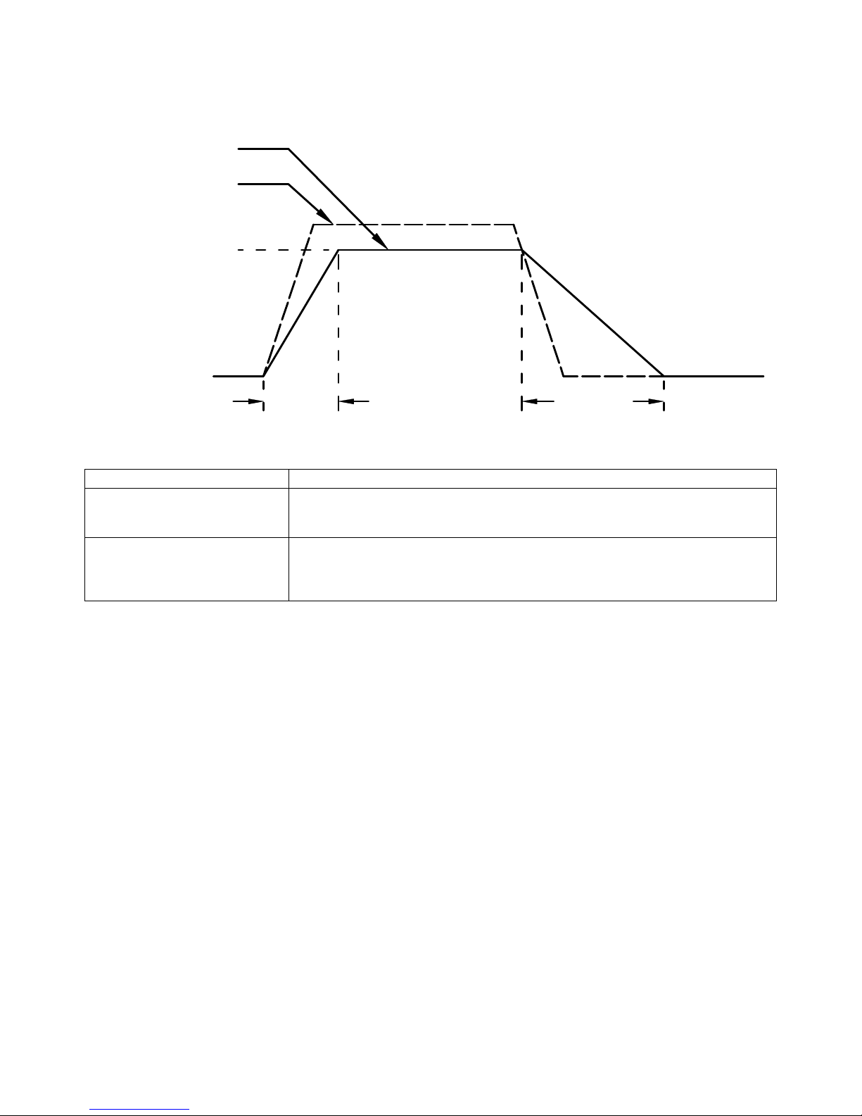
Diagram: Effects of Limits on Velocity Command
The following diagram illustrates the effects of the velocity loop limits.
Limited Velocity
Commanded Velocity
Vel Limit
Accel Limit Decel Limit
Velocity Loop Gains
The velocity loop uses these gains:
Gain Description
Vp - Velocity loop proportional The velocity error (the difference between the actual and the limited commanded
velocity) is multiplied by this gain. The primary effect of this gain is to increase
bandwidth (or decrease the step-response time) as the gain is increased.
Vi - Velocity loop integral The integral of the velocity error is multiplied by this value. Integral gain reduces the
velocity error to zero over time. It controls the DC accuracy of the loop, or the
flatness of the top of a square wave signal. The error integral is the accumulated
sum of the velocity error value over time.
Velocity Loop Gains Scalar
The Enable Gains Scalar feature increases or decreases the resolution of the units used to
express Vp and Vi, providing more precise tuning.
Velocity Loop Command and Output Filters
The velocity loop contains two programmable digital filters. The input filter should be used to
reduce the effects of a noisy velocity command signal. The output filter can be used to reduce the
excitation of any resonance in the motion system.
Two filter classes can be programmed: the Low-Pass and the Custom Bi-Quadratic. The LowPass filter class includes the Single-Pole and the Two-Pole Butterworth filter types. The Custom
Bi-Quadratic filter allows advanced users to define their own filters incorporating two poles and two
zeros.
For more information on the velocity loop filters, see the CME 2 User Guide.
Velocity Loop Outputs
The output of the velocity loop is a current command used as the input to the current loop.
Copley Controls Corp. 21
Page 22
Operational Theory Xenus XTL User Guide
2.5.4: Position Mode and Position Loop
Position Loop Diagram
The amplifier receives position commands from the digital or analog command inputs, over the
CAN interface or serial bus, or from the CVM Control Program. When using digital or analog
inputs, the amplifier's internal trajectory generator calculates a trapezoidal motion profile based on
trajectory limit parameters. When using the CAN bus, serial bus, or CVM Control Program, a
trapezoidal or S-curve profile can be programmed. The trajectory generator updates the
calculated profile in real time as position commands are received.
The output of the generator is an instantaneous position command (limited position). In addition,
values for the instantaneous profile velocity and acceleration are generated. These signals, along
with the actual position feedback, are processed by the position loop to generate a velocity
command.
To bypass the trajectory generator while in digital or analog position modes, set the maximum
acceleration to zero. The only limits in effect will now be the velocity loop velocity limit and the
current limits. (Note that leaving the maximum acceleration set to zero will prevent other position
modes from operating correctly.)
The following diagram summarizes the position loop.
Position Loop
from motor encoder or resolver
from optional position encoder (on load)
+
+
+
Gain
Multiplier
Veloc ity
Command
Target
Po s it io n
Limits:
Max v elocity
Ma x accel
Ma x decel
Abort decel
Trajector y
Generator
Prof ile Velocity
Prof ile Acceleration
Limited Position
+
Feedback
Velocity Feed Forw ard (V ff)
Acceleration Feed Forw ard (Aff)
Position Proportional Gain (Pp)
-
Trajectory Limits
In position mode, the trajectory generator applies the following user-set limits to generate the
motion profile.
Limiter Description
Maximum Velocity Limits the maximum speed of the profile.
Maximum Acceleration Limits the maximum acceleration rate of the profile.
Maximum Deceleration Limits the maximum deceleration rate of the profile.
Abort Deceleration Specifies the deceleration rate used by the trajectory generator when motion is aborted.
Position Loop Inputs From the Trajectory Generator
The position loop receives the following inputs from the trajectory generator.
Input Description
Profile Velocity The instantaneous velocity value of the profile. Used to calculate the velocity feed forward
value.
Profile Acceleration The instantaneous acceleration/deceleration value of the profile. Used to calculate the
acceleration feed forward value.
Limited Position The instantaneous commanded position of the profile. Used with the actual position feedback to
generate a position error.
22 Copley Controls Corp.
Page 23

Xenus XTL User Guide Operational Theory
Position Loop Gains
The following gains are used by the position loop to calculate the velocity command:
Gain Description
Pp - Position loop proportional The loop calculates the position error as the difference between the actual and
limited position values. This error in turn is multiplied by the proportional gain value.
The primary effect of this gain is to reduce the following error.
Vff - Velocity feed forward The value of the profile velocity is multiplied by this value. The primary effect of this
gain is to decrease following error during constant velocity.
Aff - Acceleration feed forward The value of the profile acceleration is multiplied by this value. The primary effect of
this gain is to decrease following error during acceleration and deceleration.
Gain Multiplier The output of the position loop is multiplied by this value before being passed to the
velocity loop.
Position Loop Feedback
Xenus supports two position feedback configurations
• Single sensor. Position loop feedback comes from the encoder or resolver on the motor.
• Dual sensor. Position loop feedback comes from the encoder attached to the load.
(Note that in either case, velocity loop feedback comes from the motor encoder or resolver.) For
more information, see Feedback (p. 16).
Position Loop Output
The output of the position loop is a velocity command used as the input to the velocity loop.
2.5.5: Input Command Types
The amplifier can be controlled by a variety of external sources: analog voltage or digital inputs,
CAN network (CANopen or DeviceNet), or over an RS-232 serial connection using ASCII
commands. The amplifier can also function as a stand-alone motion controller running an internal
CVM program or using its internal function generator.
2.5.6: Analog Command Input
Overview
The amplifier can be driven by an analog voltage signal through the analog command input. The
amplifier converts the signal to a current, velocity, or position command as appropriate for current,
velocity, or position mode operation, respectively.
The analog input signal is conditioned by the scaling, dead band, and offset settings.
Scaling
The magnitude of the command generated by an input signal is proportional to the input signal
voltage. Scaling controls the input-to-command ratio, allowing the use of an optimal command
range for any given input voltage signal range.
For example, in current mode, with default scaling, +10 Vdc of input generates a command equal
to the amplifier’s peak current output; +5 Vdc equals half of that.
Scaling could also be useful if, for example, the signal source generates a signal range between 0
and +10 Vdc, but the command range only requires +7.5 Vdc of input. In this case, scaling allows
the amplifier to equate +7.5 Vdc with the amplifier’s peak current (in current mode) or maximum
velocity (in velocity mode), increasing the resolution of control.
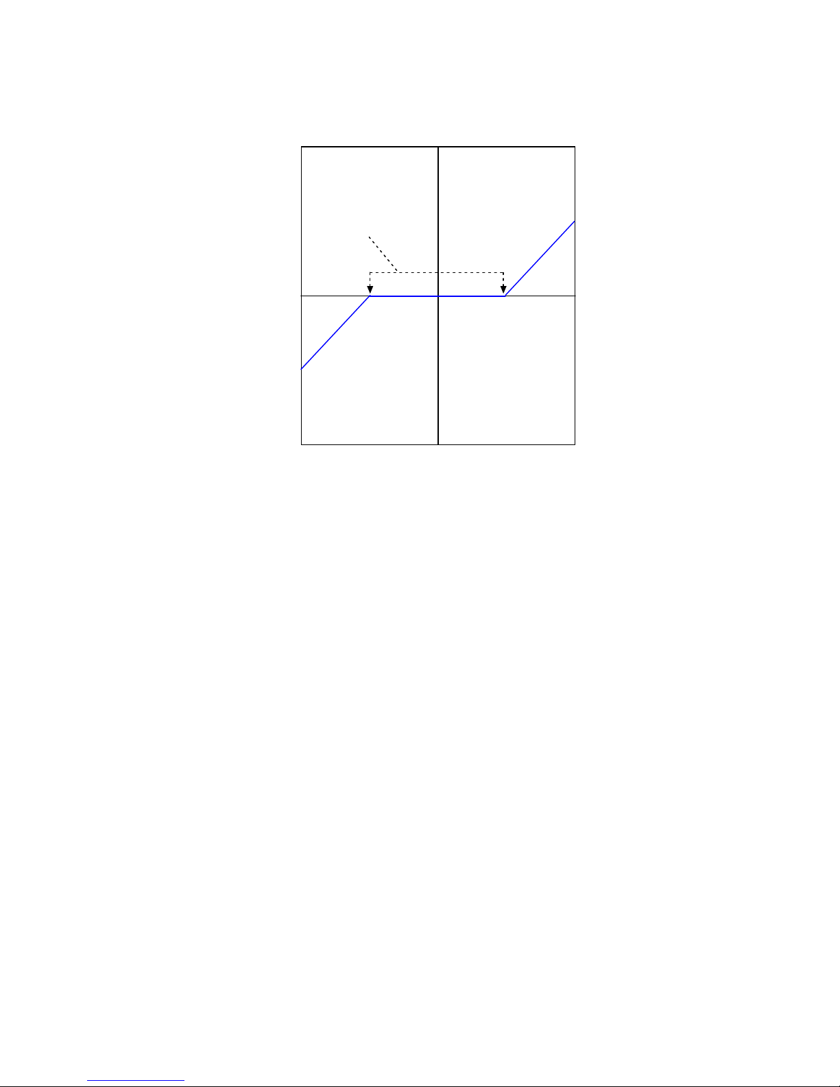
Dead Band
To protect against unintended response to low-level line noise or interference, the amplifier can be
programmed with a “dead band” to condition the response to the input signal voltage. The
Copley Controls Corp. 23
Page 24
Operational Theory Xenus XTL User Guide
amplifier treats anything within the dead band ranges as zero, and subtracts the dead band value
from all other values. For instance, with a dead band of 100 mV, the amplifier ignores signals
between –100 mV and +100 mV, and treats 101 mV as 1 mV, 200 mV as 100 mV, and so on.
200
100
0
Output
-100
-200
Dead Band
0 200-200 -100 100
Input
Offset
To remove the effects of voltage offsets between the controller and the amplifier in open loop
systems, CME 2 provides an Offset parameter and a Measure function. The Measure function
takes 10 readings of the analog input voltage over a period of approximately 200 ms, averages
the readings, and then displays the results. The Offset parameter allows the user to enter a
corrective offset to be applied to the input voltage.
The offset can also set up the amplifier for bi-directional operation from a uni-polar input voltage.
An example of this would be a 0 to +10 Vdc velocity command that had to control 1000 rpm CCW
to 1000 rpm CW. Scale would be set to 2000 rpm for a +10 Vdc input and Offset set to -5V. After
this, a 0 Vdc input command would be interpreted as -5 Vdc, which would produce 1000 rpm CCW
rotation. A +10 Vdc command would be interpreted as +5 Vdc and produce 1000 rpm CW rotation.
Monitoring the Analog Command Voltage
The analog input voltage can be monitored in the CME 2 control panel and oscilloscope. The
voltage displayed in both cases is after both offset and deadband have been applied.
Analog Command in Position Mode
The Xenus Analog Position command operates as a relative motion command. When the amplifier
is enabled the voltage on the analog input is read. Then any change in the command voltage will
move the axis a relative distance, equal to the change in voltage, from its position when enabled.
To use the analog position command as an absolute position command, the amplifier should be
homed every time it is enabled. The Homing sequence may be initiated by CAN, ASCII serial, or
CVM Indexer program commands.
24 Copley Controls Corp.
Page 25
Xenus XTL User Guide Operational Theory
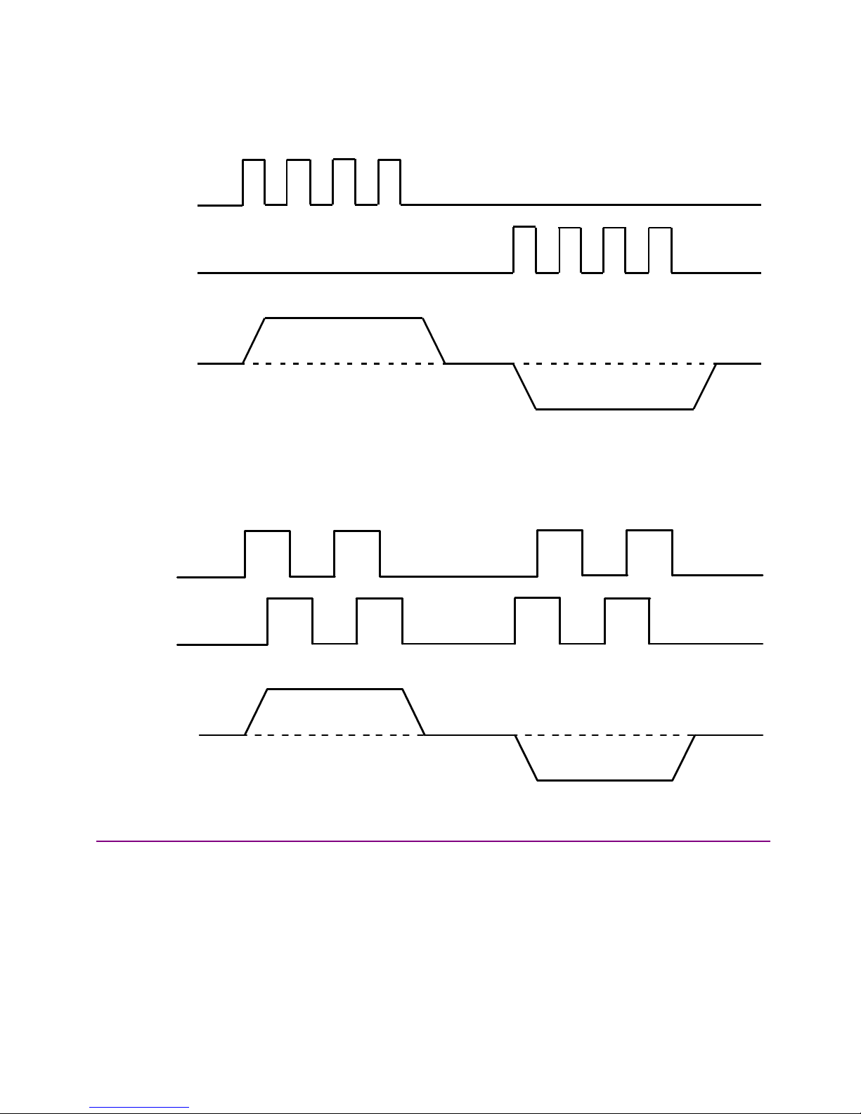
2.5.7: PWM Input
Two Formats
The amplifier can accept a pulse width modulated signal (PWM) signal to provide a current
command in current mode and a velocity command in velocity mode. The PWM input can be
programmed for two formats: 50% duty cycle (one-wire) and 100% duty cycle (two-wire).
50% Duty Cycle Format (One-Wire)
The input takes a PWM waveform of fixed frequency and variable duty cycle. As shown below, a
50% duty cycle produces zero output from the amplifier. Increasing the duty cycle toward 100%
commands a positive output, and decreasing the duty cycle toward zero commands a negative
output.
Decreasing Duty Cycle Increasing Duty Cycle
P
WM Input
50 % Duty Cycle
Max +
Amplifier Output
0
Max -
The command can be inverted so that increased duty cycle commands negative output and vice
versa.
100% Duty Cycle Format (Two-Wire)
One input takes a PWM waveform of fixed frequency and variable duty cycle, and the other input
takes a DC level that controls the polarity of the output. A 0% duty cycle creates a zero command,
and a 100% duty cycle creates a maximum command level. The command can be inverted so that
increasing the duty cycle decreases the output and vice versa.
100%
Duty Cycle
PWM Input
Direction Input
Max +
100%
Duty Cycle
Amplifier Output
0
Min -
Failsafe Protection from 0 or 100% Duty Cycle Commands
In both formats, the amplifier can be programmed to interpret 0 or 100% duty cycle as a zero
command. This provides a measure of safety in case of a controller failure or a cable break.
Copley Controls Corp. 25
Page 26

Operational Theory Xenus XTL User Guide
2.5.8: Digital Input
Three Formats
In position mode, the amplifier can accept position commands via two digital inputs, using one of
these signal formats: pulse and direction, count up/count down, and quadrature.
In all three formats, the amplifier can be configured to invert the command.
Pulse Smoothing
In position mode, the amplifier’s trajectory generator ensures smooth motion even when the
command source cannot control acceleration and deceleration rates.
When using digital or analog command inputs, the trajectory generator can be disabled by setting
the Max Accel limit to zero. (Note that when using the CAN bus, serial bus, or CVM Control
Program, setting Max Accel to zero prevents motion.)
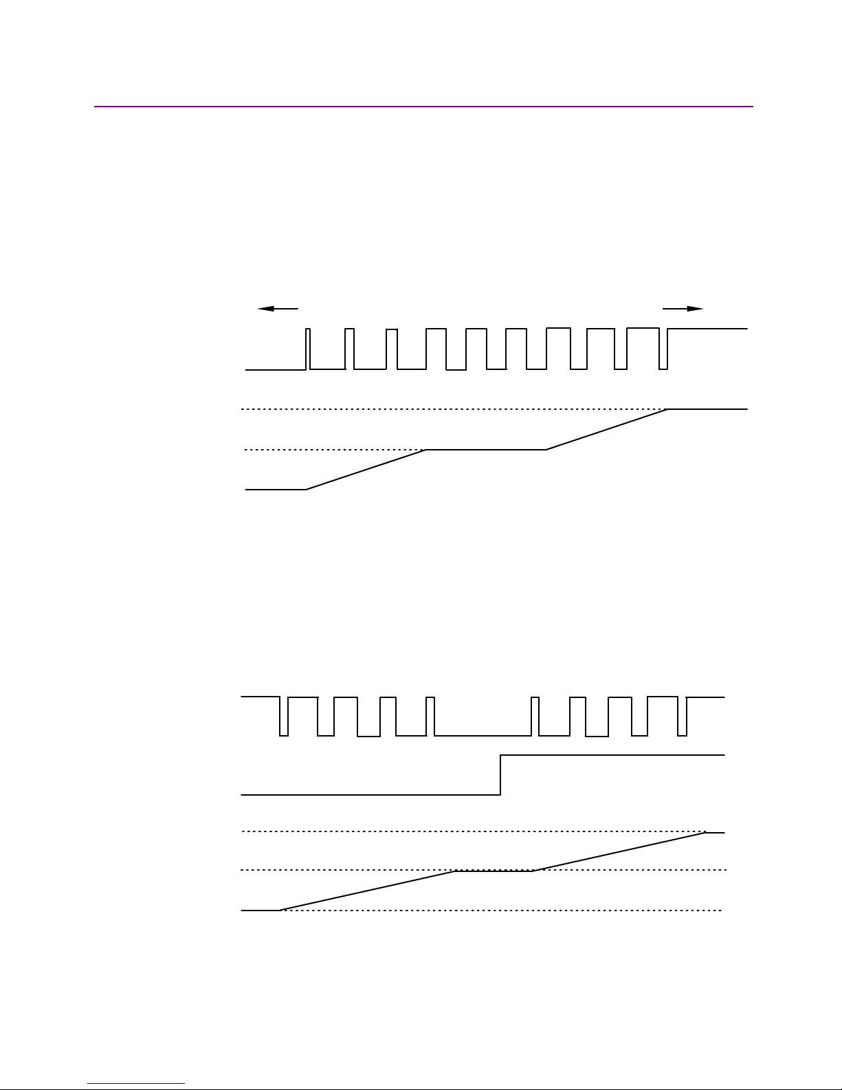
Pulse and Direction Format
In pulse and direction format, one input takes a series of pulses as motion step commands, and
another input takes a high or low signal as a direction command, as shown below.
Pulse Input
Direction Input
Velocity
Command
The amplifier can be set to increment position on the rising or falling edge of the signal. Stepping
resolution can be programmed for electronic gearing.
26 Copley Controls Corp.
Page 27
Xenus XTL User Guide Operational Theory
Count Up/Count Down Format
In the count up/count down format, one input takes each pulse as a positive step command, and
another takes each pulse as a negative step command, as shown below.
Up Input
Down Input
Velocity
Command
The amplifier can be set to increment position on the rising or falling edge of the signal. Stepping
resolution can be programmed for electronic gearing.
Quadrature Format
In quadrature format, A/B quadrature commands from a master encoder (via two inputs) provide
velocity and direction commands, as shown below.
A Input
B Input
Vel oc ity
Command
The ratio can be programmed for electronic gearing.
2.5.9: CVM Program
The Copley Virtual Machine (CVM) is a software program that runs motion control programs on
supported Copley Controls amplifiers. When a CVM program is running, the amplifier can receive
input commands from the CVM program.
For more information, see the Copley Indexer Program User’s Guide.
Copley Controls Corp. 27
Page 28

Operational Theory Xenus XTL User Guide
2.6: CANopen Operation
2.6.1: CAN Network and CANopen Profiles for Motion
In position mode, the amplifier can take instruction over a two-wire Controller Area Network
(CAN). CAN specifies the data link and physical connection layers of a fast, reliable network.
CANopen is a set of profiles (specifications) built on a subset of the CAN application layer
protocol. These profiles specify how various types of devices, including motion control devices,
can use the CAN network in a highly efficient manner. Xenus supports the relevant CANopen
profiles, allowing it to operate in the following modes of operation: profile torque, profile velocity,
profile position, interpolated position, and homing.
2.6.2: Supported CANopen Modes
In profile torque mode, the amplifier is programmed with a torque command. When the amplifier is
enabled, or the torque command is changed, the motor torque ramps to the new value at a
programmable rate. When the amplifier is halted, the torque ramps down at the same rate.
In profile velocity mode, the amplifier is programmed with a velocity, a direction, and acceleration
and deceleration rates. When the amplifier is enabled, the motor accelerates to the set velocity
and continues at that speed. When the amplifier is halted, the velocity decelerates to zero.
In profile position mode, the amplifier is programmed with a velocity, a relative distance or
absolute position, and acceleration and deceleration rates. On command, a complete motion
profile is executed, traveling the programmed distance or ending at the programmed position. The
amplifier supports both trapezoidal and s-curve profiles.
In PVT mode, the controller sends the amplifier a sequence of points, each of which is a segment
of a larger, more complex move, rather than a single index or profile. The amplifier then uses
cubic polynomial interpolation to “connect the dots” so that the motor reaches each point at the
specified velocity at the programmed time.
Homing mode is used to move the axis from an unknown position to a known reference or zero
point with respect to the mechanical system. The homing mode is configurable to work with a
variety of combinations of encoder index, home switch, and limit switches.
28 Copley Controls Corp.
Page 29
Xenus XTL User Guide Operational Theory
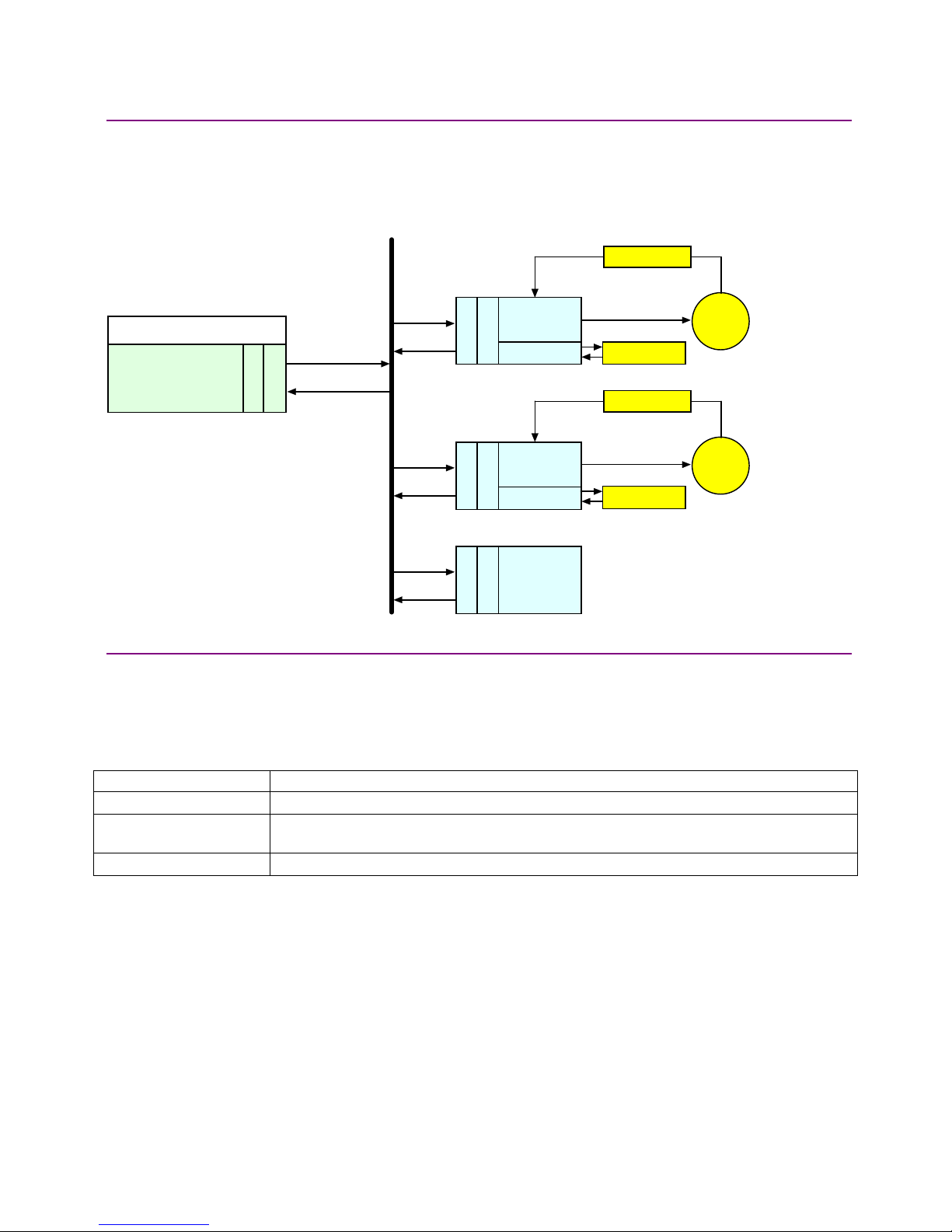
2.6.3: Architecture
As shown below, in a CANopen motion control system, control loops are closed on the individual
amplifiers, not across the network. A master application coordinates multiple devices, using the
network to transmit commands and receive status information. Each device can transmit to the
master or any other device on the network. CANopen provides the protocol for mapping device
and master internal commands to messages that can be shared across the network.
Feedback
S
oftw are Application
Master Controller
Xenus
Amplifier
CANopen
CANopen
CANopen
I/O
Xenus
Amplifier
I/O
Other
CANopen
Device
C
ontrol
Status
CAN port
CANopen
CAN Network
CAN port
CAN port
CAN port
Local Control
Sensor
Feedback
Local Control
Sensor
Motor
Motor
2.6.4: CAN Addressing
A CANopen network can support up to 127 nodes. Each node must have a unique and valid
seven-bit address (Node ID) in the range of 1-127. (Address 0 is reserved and should only be
used when the amplifier is serving as a CME 2 serial port multi-drop gateway.)
There are several basic methods for setting the CAN address, as described below. These method
can be used in any combination, producing a CAN address equal to the sum of the settings.
Addressing Method Description
Use switch If the address number <= 15, CAN address can be set using the CAN ADDR switch only.
Use inputs Use the amplifier’s programmable digital inputs (user selects how many (1-7) and which
inputs are used).
Use programmed value Program address into flash only.
For more information on CAN addressing, see CAN Interface (p. 109).
For more information on CANopen operations, see the following Copley Controls documents:
• CANopen Programmer’s Manual
• CML Reference Manual
• Copley Motion Objects Programmer’s Guide
Copley Controls Corp. 29
Page 30
Operational Theory Xenus XTL User Guide
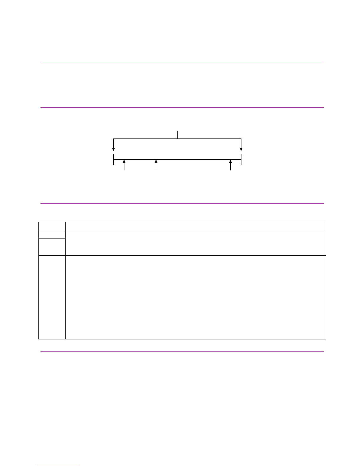
2.7: Limit Switches
2.7.1: Use Digital Inputs to Connect Limit Switches
Limit switches help protect the motion system from unintended travel to the mechanical limits. Any
of the digital inputs 2-12 can be can be programmed as positive or negative limit switch inputs.
With the amplifier operating as a CAN node, an input can also be programmed as a home limit
switch for CANopen homing operations.
2.7.2: Diagram: Sample Placement of Limit Switches
The following diagram shows these limit switches in use on a sample motion stage.
Mechanical Limits of Motion Stage
Negative
Limit
Sw itch
Home
Sw itch
Positive
Limit
Sw itch
2.7.3: How the Amplifier Responds to Limit Switch Activation
The amplifier stops any motion in the direction of an active limit switch, as described below. The
response is identical in current and velocity modes, and slightly different in position mode.
Mode Amplifier Response to Active Positive (or Negative) Limit Switch
Current
Velocity
Position Amplifier stops responding to position commands until the amplifier is disabled and re-enabled, or the fault
Amplifier prohibits travel in positive (or negative) direction. Travel in the opposite direction is still allowed.
Amplifier status indicator flashes green at fast rate.
Warning is displayed on CME 2 Control Panel and CME 2 Control Panel limit indicator turns red.
is cleared over the CANopen interface.
Amplifier status indicator flashes green at fast rate.
Warning is displayed on CME 2 Control Panel and CME 2 Control Panel limit indicator turns red.
Default behavior: If, after re-enabling the amp, the limit switch is still active, the amplifier will only allow
movement in the opposite direction.
“Hold position” behavior: If the *Hold position when limit switch is active option is set, the amplifier
prevents any motion while a limit switch is active.
CAUTION: If the amplifier is switched back to current or velocity mode with this option selected, the limit
switches will no longer function.
For more information on *Hold position when limit switch is active, see Digital Inputs (p. 93).
2.7.4: Using Custom Output to Signal Limit Switch Activation
In addition to the response described above, any of the amplifier’s digital outputs can be
configured to go active when a positive or negative limit switch is activated. For more information,
see Custom Digital Output Settings: Custom Event (p. 96).
30 Copley Controls Corp.
Page 31

Xenus XTL User Guide Operational Theory
2.8: Brake Operation
2.8.1: Digital Output Controls Brake
Many control systems employ a brake to hold the axis when the amplifier is disabled. Digital output
4 (OUT4) is designed specifically for a brake output. (Other outputs can be used for brake control,
but OUT4 is recommended.) Unlike the other outputs, OUT4 is optically isolated from the control
signals and has an internal fly back diode connected to the +24 Vdc input. By eliminating the need
to connect into the amplifier control connector, having the brake output on the +24 Vdc power
connector simplifies wiring when the brake wires are in the power cable of the motor.
For more information, see Brake Output (p. 47) and Logic Supply / Brake (J4) (p. 60).
2.8.2: Brake/Stop Sequences
Disabling the amplifier by a hardware or software command starts the following sequence of
events.
• The motor begins to decelerate (at Abort Deceleration rate in position mode or Fast Stop
Ramp rate in velocity mode). At the same time, the Brake/Stop Delay Time count begins. This
allows the amplifier to slow the motor before applying the brake.
• When the motor slows to Brake/Stop Activation Velocity OR the Brake/Stop Delay Time
expires, the brake output activates and PWM Delay Brake/Stop Response Time count begins.
• When response time has passed, the amplifier’s output stages are disabled. This delay
ensures the brake has time to lock in before disabling the power section.
This sequence is not available in the current mode of operation. Instead, in current mode, the
amplifier output turns off and the brake output activates immediately when the disable command is
received.
Copley Controls Corp. 31
Page 32

Operational Theory Xenus XTL User Guide
2.9: Status Indicators
2.9.1: Amplifier and CAN Interface Status Indicators
The amplifier’s status indicator is a bicolor LED labeled STATUS on the amplifier front panel. The
CAN interface status indicator is a bicolor LED labeled CAN. Locations are shown below.
Xenus Status Indicator
CAN Status Indicator
2.9.2: Amplifier Status Indicator Operation
Amplifier status indicator color/blink codes are described below.
Color/Blink Code Meaning
Not illuminated No +24 Vdc power to amplifier.
Steady green Amplifier is enabled and operational.
Slow-blinking green Amplifier is disabled. No faults or warnings are active.
Fast-blinking green A limit switch is active. The amplifier is enabled.
Steady red A non-latched fault has occurred.
Blinking red A latched fault has occurred.
32 Copley Controls Corp.
Page 33

Xenus XTL User Guide Operational Theory
2.9.3: CAN Interface Status Indicator Operation
The amplifier status indicator color/blink codes comply with CAN Indicator Specification 303-3 as
described below. Note that green and red codes are often interlaced, each indicating a different
set of conditions. The green codes indicate the CANopen state machine mode of operation (preoperational, operational, or stopped). The red codes indicate the status of the physical bus
(warning or error conditions).
CANopen State Machine Mode of Operation
Indicator State Diagram
Blinking green Pre-operational.
green
off
Steady green Operational
green
off
Single flash green Stopped
green
off
200
ms
200
ms
1 second
200
ms
Physical Bus Status
Single flash red Warning Limit
Reached
Double flash red Error Control Event
Triple flash red Sync Error
Steady red Bus Off
red
off
red
red
off
off
red
off
200
ms
200
ms
200
ms
200
ms
200
ms
1 second
1 second
1 second
200
ms
In addition, the CAN status indicator is turned off when the CAN node ID selector (CAN ADDR) is
set to 0. A setting of 0, which is invalid, shuts down most operations on the CAN interface, and the
light is shut off to indicate this status.
Copley Controls Corp. 33
Page 34

Operational Theory Xenus XTL User Guide
2.10: Protection
2.10.1: Faults
Overview
Xenus detects and responds to a set of conditions regarded as faults, such as amplifier over
temperature and excessive following error. When any fault occurs, with the exception of a
following error, the amplifier’s PWM output stage is disabled, the fault type is recorded in the
amplifier’s internal error log (which can be viewed with CME 2), and the status LED changes to
indicate a fault condition exists. A digital output can also be programmed to activate on a fault
condition. The following error fault behaves with slight differences, as described in
Following Error Fault Details (p. 37).
The amplifier’s PWM output stage can be re-enabled after the fault condition is corrected and the
amplifier faults are cleared. The process for clearing faults varies depending on whether the fault
is configured as non-latched or latched.
The fault-clearing descriptions below apply to all faults except for the following error fault, which is
described in Following Error Fault Details (p. 37).
Clearing Non-Latched Faults
The amplifier clears a non-latched fault, without operator intervention, as soon as the fault
condition is corrected.
Risk of unexpected motion with non-latched faults.
After the cause of a non-latched fault is corrected, the amplifier re-enables the PWM
!
DANGER
Clearing Latched Faults
A latched fault is cleared only after the fault has been corrected and at least one of the following
actions has been taken:
• power-cycle the +24 Vdc to the amplifier
• cycle (disable and then enable) an enable input that is configured as
Enables with Clear Faults or Enables with Reset
• access the CME 2 Control Panel and press Clear Faults or Reset
• clear the fault over the CANopen network or serial bus
Example: Non-Latched vs. Latched Faults
For example, the amplifier temperature reaches the fault temperature level and the amplifier
reports the fault and disables the PWM output. Then, the amplifier temperature is brought back
into operating range. If the Amplifier Over Temperature fault is not latched, the fault is
automatically cleared and the amplifier’s PWM outputs are enabled. If the fault is latched, the fault
remains active and the amplifier’s PWM outputs remain disabled until the faults are specifically
cleared (as described above).
output stage without operator intervention. In this case, motion may re-start
unexpectedly. Configure faults as latched unless a specific situation calls for nonlatched behavior. When using non-latched faults, be sure to safeguard against
unexpected motion.
Failure to heed this warning can cause equipment damage, injury, or death.
34 Copley Controls Corp.
Page 35

Xenus XTL User Guide Operational Theory
Fault Descriptions
The set of possible faults is described below. For details on limits and ranges, see
Fault Levels (p. 49).
Fault Description Fault Occurs When… Fault is Corrected When…
*Amplifier Over
Temperature
Motor Phasing Error Encoder-based phase angle does not
*Feedback error
*Motor Over Temperature Motor over-temperature switch changes
Under Voltage Bus voltage falls below specified voltage
Over Voltage Bus voltage exceeds specified voltage
*Following Error User set following error threshold
*Short Circuit Detected Output to output, output to ground, internal
Over Current (Latched) Output current I2T limit has been
*Latched by default.
Amplifier's internal temperature exceeds
specified temperature.
agree with Hall switch states. This fault can
occur only with brushless motors set up
using sinusoidal commutation. It does not
occur with resolver feedback or with Halls
correction turned off.
Over current condition detected on the
output of the internal +5 Vdc supply used
to power the feedback. Resolver or analog
encoder not connected or levels out of
tolerance.
state to indicate an over-temperature
condition.
limit.
limit.
exceeded.
PWM bridge fault.
exceeded.
Power module temperature falls below
specified temperature.
Encoder-based phase angle agrees
with Hall switch states.
Encoder power returns to specified
voltage range.
Feedback signals stay within specified
levels.
Temperature switch changes back to
normal operating state.
+ DC bus voltage returns to specified
voltage range.
+ DC bus voltage returns to specified
voltage range.
See
Position and Velocity Errors (p. 36).
Short circuit has been removed.
Amplifier is reset and re-enabled.
Copley Controls Corp. 35
Page 36

Operational Theory Xenus XTL User Guide
2.11: Position and Velocity Errors
2.11.1: Error-Handling Methods
In position mode, any difference between the limited position output of the trajectory generator
and the actual motor position is a position error. The amplifier’s position loop uses complementary
methods for handling position errors: following error fault, following error warning, and a positiontracking window.
Likewise, in velocity or position mode, any difference between the limited velocity command and
actual velocity is a velocity error. The amplifier’s velocity loop uses a velocity tracking window
method to handle velocity errors. (There is no velocity error fault.)
2.11.2: Following Error Faults
When the position error reaches the programmed fault threshold, the amplifier immediately faults.
(The following error fault can be disabled.)
For detailed information, see Following Error Fault Details (p. 37).
2.11.3: Following Error Warnings
When the position error reaches the programmed warning threshold, the amplifier immediately
sets the following error warning bit in the status word. This bit can be read over the CAN network.
It can also be used to activate a digital output.
2.11.4: Position and Velocity Tracking Windows
When the position error exceeds the programmed tracking window value, a status word bit is set.
The bit is not reset until the position error remains within the tracking window for the programmed
tracking time.
A similar method is used to handle velocity errors.
For detailed information, see Tracking Window Details (p. 38).
36 Copley Controls Corp.
Page 37

Xenus XTL User Guide Operational Theory
2.11.5: Following Error Fault Details
Position Error Reaches Fault Level
As described earlier, position error is the difference between the limited position output of the
trajectory generator and the actual position. When position error reaches the programmed
Following Error Fault level, the amplifier faults (unless the following error fault is disabled.) As with
a warning, a status bit is set. In addition, the fault is recorded in the error log.
Additional responses and considerations depend on whether the fault is non-latched or latched, as
described below.
Amplifier Response to Non-Latched Following Error Fault
When a non-latched following error fault occurs, the amplifier drops into velocity mode and applies
the Fast Stop Ramp deceleration rate to bring the motor to a halt. The amplifier PWM output stage
remains enabled, and the amplifier holds the velocity at zero, using the velocity loop.
Resuming Operations After a Non-Latched Following Error Fault
The clearing of a non-latched following error depends on the amplifier’s mode of operation.
Issuing a new trajectory command over the CAN bus, the ASCII interface, or DeviceNet will clear
the fault and return the amplifier to normal operating condition.
If the amplifier is receiving position commands from the digital or differential inputs, then the
amplifier must be disabled and then re-enabled using the amplifier’s enable input or though
software commands. After re-enabling, the amplifier will operate normally.
Amplifier Response to a Latched Following Error Fault
When a latched following error fault occurs, the amplifier disables the output PWM stage without
first attempting to apply a deceleration rate.
Resuming Operations After a Latched Following Error Fault
A latched following error fault can be cleared using the steps used to clear other latched faults:
• power-cycle the +24 Vdc to the amplifier
• cycle (disable and then enable) an enable input that is configured as
Enables with Clear Faults or Enables with Reset
•
access the CME 2 Control Panel and press Clear Faults or Reset
• clear the fault over the CANopen network or serial bus
Copley Controls Corp. 37
Page 38

Operational Theory Xenus XTL User Guide
2.11.6: Tracking Window Details
Proper Tracking Over Time
As described earlier, position error is the difference between the limited position output of the
trajectory generator and the actual position. Velocity error is the difference between commanded
and actual velocity.
When the position or velocity error exceeds the programmed tracking window value, a status word
bit is set. The bit is not reset until the error remains within the tracking window for the programmed
tracking time.
Velocity Tracking Illustration
The following diagram illustrates the use of tracking window and time settings in velocity mode.
Actual Velocity
Limited Velocity
Trac king W ind ow
Output
± Tracking W indow
Tracking
Time
38 Copley Controls Corp.
Page 39

Xenus XTL User Guide Operational Theory
2.12: Communication
2.12.1: Communication Interfaces
As described below, the amplifier features two communication interfaces, each used for different
purposes.
Interface Description
RS-232 port The amplifier features a three-wire RS-232 port. CME 2 software communicates with the
amplifier using a binary protocol over this link for commissioning, adjustments, and
diagnostics. In addition, ASCII commands can be issued over the serial port. For RS-232
port specifications, see Serial Interface (p. 49). For RS-232 port wiring instructions, see
RS-232 Serial Communications (J5) (p. 61).
In an RS-232 multi-drop configuration, a single amplifier with a serial connection to a
controller can act as a gateway. Through the gateway amplifier, the controller can use the
serial connection to access other amplifiers on the CAN bus.
CME 2 can be used over a direct RS-232 connection to make adjustments and monitor
operations even when the amplifier is being controlled over the CAN interface or by the
digital inputs.
CAN interface When operating as a CANopen or DeviceNet node, the amplifier takes input commands
over a CAN bus. CAN communications are described in CME 2 and CAN Operation (p.
39). DeviceNet is described in the Copley DeviceNet Programmer’s Guide.
2.12.2: CME 2 and CAN Operation
When the amplifier is operated as a CANopen or DeviceNet node, CME 2 can be used for
programming before and after installation in a CAN network.
CME 2 can also monitor operations while the amplifier is operating as a CANopen or DeviceNet
node.
If CME 2 is used to initiate any movement (using the Control Panel Jog feature or a scope
function), the amplifier’s CANopen or DeviceNet operations are suspended. When adjustments
are complete, CME 2 relinquishes returns the amplifier to the CANopen or DeviceNet node state.
Using CME 2 can affect or suspend CAN operations.
When operating the amplifier as a CANopen or DeviceNet node, use of CME 2 to
!
DANGER
change amplifier parameters can affect CANopen or DeviceNet operations in
progress.
Using CME 2 to initiate motion can cause CANopen operations to suspend. The
operations may restart unexpectedly when the CME 2 move is stopped.
Failure to heed this warning can cause equipment damage, injury, or death.
Copley Controls Corp. 39
Page 40

Operational Theory Xenus XTL User Guide
2.13: Inputs
2.13.1: Digital Inputs
The amplifier has twelve digital inputs (IN1-IN12). Eleven of them appear on the control connector.
IN5 appears on the feedback connector, and is intended for the motor over temperature switch
(although it can be programmed for any function). For a list of input functions, see Digital Input
Functions (p. 94 ).
2.13.2: Input Filters
Two types of input RC filters are used: GP (general-purpose) and HS (high-speed). Input
reference functions such as Pulse and Direction, Pulse Up/Pulse Down, and Quadrature A/B are
wired to inputs that have the HS filters, and inputs with the GP filters are used for general-purpose
logic functions, limit switches, and the motor temperature sensor.
2.13.3: Debounce Time
To prevent undesired multiple triggering caused by switch bounce upon switch closures, each
input can be programmed with a debounce time. The programmed time specifies how long an
input must remain stable at a new state before the amplifier recognizes the state. The debounce
time is ignored if the input is used as a digital command input.
2.13.4: Configure for Pull Up/Pull Down Resistors by Groups
Pre-defined groups of inputs can be programmed to have either an internal pull up or pull down
resistor. See J7 Pin Description (p. 64)
for groupings.
40 Copley Controls Corp.
Page 41

Xenus XTL User Guide Operational Theory
2.14: Outputs
2.14.1: Digital Outputs
The amplifier has four programmable digital outputs. Three of the outputs (OUT1 - 3) are generalpurpose outputs. The fourth (OUT4) is specifically designed as a brake output but can be
programmed to perform any of the functions. For a list of digital output functions, see Standard
Digital Outputs (p. 95).
The general-purpose outputs are open-drain MOSFETs, each with a pull-up resistor, in series with
a diode, connected to the amplifier’s internal +5 Vdc supply. This design allows the outputs to be
directly connected to optically isolated PLC inputs that reference a voltage higher than
+5 Vdc, typically +24 Vdc. The diode prevents current flow between the +24 Vdc supply and the
internal +5 Vdc supply though the pull-up resistor. This current, if allowed to flow, could turn on the
PLC input, giving a false indication of the amplifier’s true output state.
The general-purpose outputs require an external fly-back diode to be installed across any
inductive loads, such as relays, that are connected to them.
The brake output (OUT4) is described in Brake Operation (p. 31).
Copley Controls Corp. 41
Page 42

Operational Theory Xenus XTL User Guide
2.15: Regen Resistor Theory
2.15.1: Regeneration
When a load is accelerated electrical energy is converted into mechanical energy. During
deceleration the conversion is reversed. This is called regeneration. Some of this regenerated
energy is lost to friction in the mechanical system. More of this energy is converted to heat due to
2
I
R losses in the motor windings, cabling, and drive electronics. The remainder of the energy is
added to the electrical energy already stored in the internal capacitor bank of the amplifier. The
result of this energy being added is an increase in the voltage on the capacitor bank.
2.15.2: Regen Resistor
If too much energy is added to the capacitor bank, the voltage rises to a point where the
amplifier's over voltage protection shuts down the amplifier. To prevent this, a regen circuit shunts
some of the energy into an external regen resistor when the voltage rises too high.
2.15.3: Regen Circuit Components
The amplifier provides an internal transistor that is used in combination with an external resistor.
Copley Controls supplies compatible resistors as described in Regen Resistor Assemblies (p.
177). When using a resistor acquired from another source, be sure it meets the specifications
described in Regen Resistor Sizing and Configuration (p. 145).
2.15.4: Regen Circuit Protections
The amplifier protects the regen circuit against short circuit, and uses I2T peak current/time
algorithms to protect both the external resistor and the internal transistor.
2.15.5: Configurable Custom Resistor
The following values can be entered for a custom resistor using CME 2:
Option Description
Resistance Value Value in ohms of the resistor
Continuous Power Continuous power rating of the resistor
Peak Power Peak power rating of the resistor
Time at Peak Power Time at peak power of resistor
For more information, see Regen Resistor (p. 102) and
Regen Resistor Sizing and Configuration (p. 145)
42 Copley Controls Corp.
Page 43

CHAPTER
3: SPECIFICATIONS
This chapter describes the amplifier specifications. Contents include:
Title Page
3.1: Agency Approvals.................................................................................................................................................................44
3.2: Power Input ..........................................................................................................................................................................44
3.3: Power Output........................................................................................................................................................................ 44
3.4: Control Loops ....................................................................................................................................................................... 45
3.5: Regen Circuit Output ............................................................................................................................................................ 45
3.6: Digital Command Input ......................................................................................................................................................... 45
3.7: Analog Command Input........................................................................................................................................................46
3.8: Digital Inputs.........................................................................................................................................................................46
3.9: Digital Outputs......................................................................................................................................................................46
3.10: Brake Output ...................................................................................................................................................................... 47
3.11: Encoder Power Supply Output............................................................................................................................................ 47
3.12: Primary Encoder Inputs ...................................................................................................................................................... 47
3.13: Analog Encoder Inputs .......................................................................................................................................................47
3.14: Hall Switch Inputs...............................................................................................................................................................48
3.15: Resolver Interface .............................................................................................................................................................. 48
3.16: Multi-Mode Port .................................................................................................................................................................. 48
3.17: Serial Interface ................................................................................................................................................................... 49
3.18: CAN Interface.....................................................................................................................................................................49
3.19: Status Indicators................................................................................................................................................................. 49
3.20: Fault Levels ........................................................................................................................................................................ 49
3.21: Power Dissipation............................................................................................................................................................... 50
3.22: Thermal Impedance............................................................................................................................................................50
3.23: Mechanical and Environmental...........................................................................................................................................50
3.24: Dimensions......................................................................................................................................................................... 51
Copley Controls Corp. 43
Page 44

Specifications Xenus XTL User Guide
3.1: Agency Approvals
• CE Compliance*:
EN 55011 Compatibility
EN 61000-6-1 Immunity
EN 61010-1 Safety
• UL 508C Compliant
• RoHS Compliant
*CE Declaration of Conformity available at
http://www.copleycontrols.com/Motion/Downloads/xenusData.html
3.2: Power Input
Model XTL-230-18 (-R, -S) XTL-230-36 (-R, -S) XTL-230-40 (-R, -S)
Mains Voltage 100 - 240 Vac
1 Ø or 3 Ø
Mains Frequency 47 to 63 Hz
Mains Current 15 Arms maximum 20 Arms maximum
Current Inrush
Logic Supply Voltage +20 to +32 Vdc
Logic Supply Current 500 mA maximum
15 A peak at 120 Vac
35 A peak at 240 Vac
3.3: Power Output
Model XTL-230-18 (-R, -S) XTL-230-36 (-R, -S) XTL-230-40 (-R, -S)
Peak Current 18 Adc
[12.7 Arms]
Peak Current Time 1 Second
Continuous Current* 6 Adc
[4.24 Arms]
Efficiency >97% @ 230 Vac and rated continuous current
Output Type 3-phase IGBT inverter
15 kHz center-weighted PWM
space-vector modulation
PWM Ripple Frequency 30 kHz
Minimum Load
Inductance
* Heat sinking and/or forced air cooling required for continuous output power rating
** Consult factory for operation with inductance lower than 400 uH
NOTE: See Xenus Filter (p. 163).
36 Adc
[25.5 Arms]
12 Adc
[8.5 Arms]
400 uH line-to-line**
40 Adc
[28.3 Arms]
20 Adc
[14.1 Arms]
44 Copley Controls Corp.
Page 45

Xenus XTL User Guide Specifications
3.4: Control Loops
Type
Current
Velocity
Position
Sampling rate (time)
Current
Velocity
Position
Current Loop Small Signal
Bandwidth
Velocity Loop Filters
Type
Frequency Range
Bus Voltage Compensation Changes in bus or mains voltage do not affect tuning.
100% digital.
15 kHz (67 Ps)
3 kHz (333 Ps)
3 kHz (333 Ps)
> 2 kHz (Tuning and load impedance dependent)
Programmable
Programmable
Low Pass, 1 Pole
Low Pass, Butterworth, 2 Poles
Bi-Quadratic, 2 Poles & 2 Zeros
20 - 1500 Hz
3.5: Regen Circuit Output
Model XTL-230-18 (-R, -S) XTL-230-36 (-R, -S) XTL-230-40 (-R, -S)
Continuous Power 2 kW 4 kW
Peak Power 5 kW 10 kW
Minimum Resistance
Minimum Resistor Wattage 25 W 50 W
Turn On Voltage +390 Vdc
Turn Off Voltage +380 Vdc
DC Bus Capacitance
Regen Energy Absorption
Capacity
Input Voltage 120 Vac 108 joules
208 Vac 57 joules
240 Vac 32 joules
30 15
1760 µF nominal
3.6: Digital Command Input
Digital Position Command
Command
Pulse and direction,
Count up/ count down
maximum rate
Quadrature A/B encoder
maximum rate
PWM frequency range 1 kHz - 100 kHz Digital Current & Velocity
PWM minimum pulse width 220 nSec
2 MHz (with active driver)
2 M line/sec (8 M count/sec after
quadrature)
Copley Controls Corp. 45
Page 46

Specifications Xenus XTL User Guide
3.7: Analog Command Input
Channels 1
Type Differential, non-isolated
Measurement Range ±10 Vdc
Maximum Voltage
Differential
Input to Ground
Input Impedance
Resolution 12 Bit
Bandwidth 7 kHz
±10 Vdc
±10 Vdc
66 k
Scan Time
Function Current, velocity, or position command
67 µSec
3.8: Digital Inputs
Channels 12*
7 general-purpose
5 high-speed
Type 74HC14 Schmitt trigger w/ RC filter
10 k resistor programmable as pull up or pull down to internal +5 Vdc.
Input Voltage Range
General-Purpose
High-speed
Logic Low Input Voltage < +1.35 Vdc
Logic High Input Voltage > +3.65 Vdc
Scan Time
RC Filter Time Constant
General-Purpose
High-speed
Debounce
Type
Time
Function IN1 enable
Note: Inputs 7&9 and 8&10 can be programmed to function as differential pairs.
0 V - +28 Vdc
0 V - +12 Vdc
333 µSec
330 µSec
100 nSec
Digital
Programmable 0 - 10,000 mSec
IN2 - IN12 programmable
3.9: Digital Outputs
Channels 3
Type Current-sinking MOSFET, non-isolated
Maximum Voltage +40 Vdc
Maximum Sink Current 1 A
Low Level Output Resistance
Function Programmable
46 Copley Controls Corp.
1 k pullup to internal +5 Vdc through diode
<0.2
Page 47

Xenus XTL User Guide Specifications
3.10: Brake Output
Channels 1
Type Current-sinking MOSFET, optically isolated from control/logic ground.
Referenced to +24 Vdc logic supply.
Internal fly back diode to +24 Vdc.
Maximum Sink Current 1 A
Low Level Output Resistance
Function Primary function is brake control.
<0.2
May be programmed to other functions.
3.11: Encoder Power Supply Output
Voltage Output +5 Vdc ±2%
Maximum Current Output 400 mA
Short Circuit Protection Fold-back current limiting
Function Provides power for motor encoder and/or Hall switches.
3.12: Primary Encoder Inputs
Channels 3
Type Differential RS-422 line receiver w/ RC filter
Non-isolated
Signals A, /A, B, /B, X*, /X*
Input Voltage Range ±7 Vdc
Differential Input Threshold ±0.2 Vdc
Termination Resistance
Maximum Frequency 5 MHz Line (20 Mcount/sec)
Function Incremental or analog encoder or resolver required for sinusoidal commutation
* X is equivalent to Marker, Index, or Z channels, depending on the encoder manufacturer. This channel is only
required in certain homing modes while under CAN control.
121
and position or velocity modes of operation.
3.13: Analog Encoder Inputs
Channels 2
Type Differential, non-isolated
Signals Sin, cosine
Nominal Voltage 1 Vdc-pk
Maximum Voltage
Differential
Input to Ground
Differential Input Impedance
Bandwidth 230 kHz
Interpolation 1 to 1024, programmable
Function Incremental or analog encoder or resolver required for sinusoidal commutation
Copley Controls Corp. 47
±0.6 Vdc
0 to +3.5 Vdc
121
and position or velocity modes of operation.
Page 48

Specifications Xenus XTL User Guide
3.14: Hall Switch Inputs
Channels 3
Type 74HC14 Schmitt trigger w/ RC Filter
10 k pull up resistor to internal +5 Vdc
Input Voltage Range 0 Vdc - +28 Vdc
Low Level Input Voltage < +1.35 Vdc
High Level Input Voltage > +3.65 Vdc
Scan Time
RC Filter Time Constant
Function Commutation of brushless motors in trapezoidal mode.
67 µSec
33 µSec
Commutation initialization and phase error detection in sinusoidal mode.
3.15: Resolver Interface
Type Transmit, 1:1 to 2:1 transformation ratio
Resolution 14 bits (equivalent to a 4096 line quadrature encoder)
Reference Frequency 7.5 kHz
Reference Voltage 3 Vrms, auto-adjustable by amplifier for proper feedback levels.
Reference Max Current 100 mA
Max RPM 10,000
Function Incremental or analog encoder or resolver required for sinusoidal commutation
and position or velocity modes of operation.
3.16: Multi-Mode Port
Channels 3
Type Bi-Directional, Differential RS-422
Non-isolated
Signals A, /A, B, /B, X, /X
Input Voltage Range ±7 Vdc
Differential Input Threshold ±0.2 Vdc
Termination Resistance None
Function
Programmable
Maximum Frequency
Output Mode
Buffered Encoder
Emulated Encoder
Input Mode
PWM Input
Digital Command
Secondary Encoder
Output Mode
Buffered primary incremental encoder
Emulated incremental encoder from analog encoder or resolver
Input Mode
Secondary incremental encoder input
Current / Velocity mode, PWM input
Position Mode, Digital command input
5 MHz Line (20 Mcount/sec)
4.5 MHz Line (18 Mcount/sec)
100Khz
5 MHz (50% Duty Cycle)
5 MHz Line (20 Mcount/sec)
48 Copley Controls Corp.
Page 49

Xenus XTL User Guide Specifications
3.17: Serial Interface
Channels 1
Type RS-232
Signals Rxd, Txd, Gnd
Baud Rate 9,600 to 115,200 (defaults to 9600 on power up or reset)
Data Format N, 8, 1
Flow Control None
Protocol Binary or ASCII format
Function Set up, control and diagnostics status
3.18: CAN Interface
Channels 1
Connectors 2 eight-position modular (RJ-45 style) wired as per CAN Cia DR-303-1, V1.1
One connector for signal input.
Second connector for daisy chaining to next node.
Signals CAN H, CAN L, CAN Gnd
(CAN +5 Vdc Pass though only)
Format CAN V2.0b physical layer for high-speed connections compliant
Protocol Motion Control Device
Under DSP-402 of the CANopen DS-301 V4.01 (EN 50325-4) Application
Layer
Supported Modes Profile Current, Velocity, and Position, PVT, and Homing
Node Address Selection 16-position rotary switch on front panel
OR programmable digital inputs
OR stored in flash memory
OR combination of above.
Bus Termination
Function Real-time motion control
External 121 resistor across CAN-H and CAN-L when termination plug is
installed in second connector.
3.19: Status Indicators
Amplifier Status Bi-Color LED on front panel, labeled Status*.
CAN Status Bi-Color LED on front panel, labeled CAN.
Conforms to CAN Indicator Specification CiA DR-303-3*.
*For status indicator locations and codes, see Status Indicators (p. 32).
3.20: Fault Levels
Amp Over Temperature > 80 °C
DC Bus Under Voltage < +60 Vdc
DC Bus Over Voltage > +400 Vdc
Encoder Power < +4.25 Vdc
Copley Controls Corp. 49
Page 50

Specifications Xenus XTL User Guide
3.21: Power Dissipation
Model:
Output Power Mains Voltage
120 Vac 30 W 55 W 92 W Maximum
Continuous
240 Vac 40 W 75 W 120 W
120
100
80
XTL-230-18 (-R, -S) XTL-230-36 (-R, -S) XTL-230-40 (-R, -S)
Power Dissipation
60
40
230 VAC
120 VAC
Power Dissipation (W)
20
0
0 5 101520
Continuous Output Current (A)
3.22: Thermal Impedance
See Thermal Considerations (p. 159).
3.23: Mechanical and Environmental
Size 7.55 in (191,8 mm) X 5.57 in (141,5 mm) X 2.57 in (65,3 mm)
Weight
Without Heat Sink
With Heat Sink XTL-HL
With Heat Sink XTL-HS
Ambient Temperature
Storage
Operating
Humidity 0% to 95%, non-condensing
Contaminants Pollution degree 2
Environment IEC68-2: 1990
Cover Material
Cooling Heat sink and/or forced air cooling required for continuous power output
3.0 lb (1.36 kg)
4.3 lb (1.95 kg)
4.8 lb (2.20 kg)
-40 to +85°C
0 to +55°C
Meets U.L. Spec 94 V-0 Flammability Rating
50 Copley Controls Corp.
Page 51

Xenus XTL User Guide Specifications
3.24: Dimensions
Copley Controls Corp. 51
Page 52

Specifications Xenus XTL User Guide
52 Copley Controls Corp.
Page 53

CHAPTER
4: WIRING
This chapter describes the wiring of amplifier and motor connections. Contents include:
Title Page
4.1: General Wiring Instructions ..................................................................................................................................................54
4.2: AC Mains (J1)....................................................................................................................................................................... 56
4.3: Motor (J2) ............................................................................................................................................................................. 57
4.4: Regen Resistor (J3) (Optional) .............................................................................................................................................59
4.5: Logic Supply / Brake (J4)...................................................................................................................................................... 60
4.6: RS-232 Serial Communications (J5)..................................................................................................................................... 61
4.7: CAN Bus (J6) ....................................................................................................................................................................... 62
4.8: Control (J7)........................................................................................................................................................................... 63
4.9: Motor Feedback (J8)............................................................................................................................................................. 67
Copley Controls Corp. 53
Page 54

Wiring Xenus XTL User Guide
4.1: General Wiring Instructions
4.1.1: Electrical Codes and Warnings
Be sure that all wiring complies with the National Electrical Code (NEC) or its national equivalent,
and all prevailing local codes.
DANGER: Hazardous voltages.
Exercise caution when installing and adjusting.
!
DANGER
!
DANGER
Failure to heed this warning can cause equipment damage, injury, or death.
Risk of electric shock.
High-voltage circuits on J1, J2, and J3 are connected to mains power.
Failure to heed this warning can cause equipment damage, injury, or death.
Do not ground mains-connected circuits.
With the exception of the ground pins on J1, J2, and J3, all of the other circuits on
!
WARNING
!
WARNING
4.1.2: Grounding Considerations
Primary Grounding Functions
A grounding system has three primary functions: safety, voltage-reference, and shielding.
J1-3 Primary Ground
The primary ground at J1-3 is the safety ground and is intended to carry the fault currents from the
mains in the case of an internal failure or short-circuit of electronic components. This ground is
connected to the amplifier chassis. Wiring to this ground should be done using the same gauge
wire as that used for the mains. This wire is a “bonding”’ conductor that should be connected to an
earthed ground point and must not pass through any circuit interrupting devices.
The pin on the amplifier at J1-3 is longer than the other pins on J1, giving it a first-make, lastbreak action so that the amplifier chassis is never ungrounded when the mains power is
connected.
these connectors are mains-connected and must never be grounded.
Failure to heed this warning can cause equipment damage.
Do not plug or unplug connectors with power applied.
The connecting or disconnecting of cables while the amplifier has 24Vdc and/or
mains power applied is not recommended.
Failure to heed this warning may cause equipment damage.
54 Copley Controls Corp.
Page 55

Xenus XTL User Guide Wiring
J2 and J3 Grounds
The ground terminals at J2-1 and J3-5 also connect to the amplifier chassis.
Motor cases can be safety-grounded in one or optionally both of these ways:
• Direct grounding of the motor frame (assuming the frame of the machine is grounded). Attach
the metal motor case to the metal machine frame or connect the ground wire of the motor to
the metal frame of the machine.
• Grounding of the motor frame through the motor power cable to amplifier J2-1. The ground
wire should be of the same gauge as the power wires.
Likewise, the case of the regen resistor can also be safety-grounded by direct grounding of the
case or by a grounding wire connected to amplifier J3-5. Again, this wire should be of the same
gauge as the other regen resistor conductors.
Cable shields, because of their smaller wire size, must not be used as part of a safety-ground
system.
Signal Grounding
The amplifier signal ground must be connected to the control system signal ground. The amplifier
signal ground is not connected to earth ground internal to the amplifier. Therefore, the control
system signal ground can be connected to earth ground without introducing a ground loop.
Shielding
Shields on cables reduce emissions from the amplifier and help protect internal circuits from
interference due to external sources of electrical noise. The shields shown in the wiring diagrams
are also required for CE compliance. Cable shields should be tied at both ends to earth or chassis
ground. The housing and pin 1 of both J7 and J8 are connected to the amplifier’s chassis.
4.1.3: Connector Locations
Connector locations (J1-J8) are shown below.
Copley Controls Corp. 55
Page 56

Wiring Xenus XTL User Guide
4.2: AC Mains (J1)
Mating Connector
Description
Manufacturer PN Wago: 51118287 or 721-204/026-045/RN01-0000
Wire size 22 - 12 AWG
Recommended Wire 18 A models: 14 AWG, 600 V
Wire Insertion/Extraction Tool Wago: 231-131
Connector and tool are included in connector kit XTL-CK or XTL-CA
Pin Description
Pin Signal Function
1 L1 AC power input (hot or L1)
2 L2 AC power input (neutral or L2)
3 Protective ground Chassis safety ground
4 L3 AC power input (L3)
AC Mains Fuse Recommendation
Recommended fuse type: Class CC, 600 Vac rated, Ferraz-Shawmut ATDR, Littelfuse CCMR,
Bussman LP-CC, or equivalent.
Euro-style 7,5 mm pluggable female terminal block
ith preceding ground receptacle.
w
36 A and 40 A models: 12 AWG, 600 V
Shielded cable required for CE compliance
56 Copley Controls Corp.
Page 57

Xenus XTL User Guide Wiring
AC Mains Wiring Diagram (Single-Phase)
Amplifier
J1-4
J1-2
J1-1
J1
L2
L1
Keep wire length
as short as
possible. Not to
exceed 1 Meter.
L
O
A
D
Line Filter*
AC Mains Wiring Diagram (Three-Phase)
Amplifier J1
J1-4
J1-2
J1-1
L3
L2
L1
Keep wire length
as short as
possible. Not to
exceed 1 Meter.
Line Filter*
C
B
A
Gnd
Fus es **
L
I
N
E
* Filter Concepts SF20L
(or equivalent)
used for CE compliance
** Not required on
a neutral line.
Fus es
C
B
A
* Filter Concepts 3F15
(or equivalent)
used for CE compliance
Earth
Ground
L2 (Neut)
L1 (Line)
L3
L2
L1
Earth
Ground
47-63 Hz
100-240 VAC
3
Ø
47-63 Hz
100-240 VAC
1
Ø
4.3: Motor (J2)
Mating Connector
Description Euro-style, 4 position, 5.0 mm pluggable female terminal block
Manufacturer PN
Wire Size 22 - 12 AWG
Recommended Wire 18 A models: 14 AWG, 600 V
Wire Insertion/Extraction Tool Wago: 231-131
Standard connector and tool are included in connector kit XTL-CK or XTL-CA
Pin Description
Pin Signal Function
1 Ground Motor frame ground and cable shield
2 W Phase W output of amplifier
3 V Phase V output of amplifier (use for DC motor connection)
4 U Phase U output of amplifier (use for DC motor connection)
Copley Controls Corp. 57
Wago: 51118008 or 721-104/026-047/RN01-0000
36 A and 40 A models: 12 AWG, 600 V
Shielded cable required for CE compliance
Page 58

Wiring Xenus XTL User Guide
Brushless Motor Wiring Diagram
Amplifier
J2-4
J2-3
J2-2
J2-1
J2
U
V
W
Brush Motor Wiring Diagram
Amplifier J2
J2-4
J2-3
J2-2
J2-1
U
V
Brushless
Motor
A
B
C
Case
Ground
Brush
Motor
+
-
Case
Ground
58 Copley Controls Corp.
Page 59

Xenus XTL User Guide Wiring
4.4: Regen Resistor (J3) (Optional)
Mating Connector
Description Euro-style, 5 position, 5.0 mm pluggable male terminal block.
Manufacturer PN
Wire Size 22 - 12 AWG
Recommended Wire 18 A models: 14 AWG, 600 V
Wire Insertion/Extraction Tool Wago: 231-131
Standard connector and tool are included in connector kit XTL-CK or XTL-CA
Pin Description
Pin Signal Function
1 Regen + + DC Bus to one side of regen resistor
2 N/C No connection
3 Regen - Collector of regen transistor to one side of regen resistor
4 N/C No connection
5 Ground Enclosure ground and cable shield
Wago: 51111277 or 721-605/000-043/RNn01-0000
36 A and 40 A models: 12 AWG, 600 V
Shielded cable required for CE compliance
Regen Resistor Wiring Diagram
Amplifier J3
+
DC Bus
J3-1
J3-2
J3-3
J3-4
J3-5
-
DC Bus
*Fuses may be required by local electrical codes
Regen
Regen
+
-
Fuses
(optional*)
Regen
Resistor
Enclosure
Regen Resistor Fusing
Recommended Fuses:
Regen Resistor Fuse type
XTL-RA-03 Cooper Bussman KLM-8, Littelfuse KLKD008, Ferraz Shawmut ATM-10 or equivalent.
XTL-RA-04 Cooper Bussman KLM-12, Littelfuse KLKD012, Ferraz Shawmut ATM-15 or equivalent.
User Supplied See Regen Resistor Sizing and Configuration (p. 145).
Copley Controls Corp. 59
Page 60

Wiring Xenus XTL User Guide
4.5: Logic Supply / Brake (J4)
Mating Connector
Description Euro-style, 3 position, 5.0 mm pluggable female terminal block.
Manufacturer PN Wago: 51117974 or 721-103/026-047/RN01-0000
Wire Size 22 - 14 AWG
Recommended Wire 18 AWG
Wire Insertion/Extraction Tool Wago: 231-131
Standard connector and tool are included in connector kit XTL-CK or XTL-CA
Pin Description
Pin Signal Function
1 RTN +24 Vdc return
2 Brake Return or low side of motor brake
3 +24 Vdc +24 Vdc Logic power supply
Logic Supply / Brake Wiring Diagram
Amplifier J4
Isolated Logic
Power Supply
Brake
J4-3
J4-2
J4-1
+24 V
Brake
RTN
+24 Vdc
Power
Supply
(Required)
60 Copley Controls Corp.
Page 61

Xenus XTL User Guide Wiring
4.6: RS-232 Serial Communications (J5)
Mating Connector
6-position, modular connector (RJ-11 style).
Copley Controls provides a prefabricated cable and modular-to-9-pin sub-D adapter in RS-232
Serial Cable Kit, PN SER-CK.
A diagram of the female connector is shown below.
123456
Pin Description
Pin Signal Function
1 N/C No connection
2 RxD Receive data input from computer
3 Signal ground Power supply ground
4 Signal ground Power supply ground
5 TxD Transmit data output to computer
6 N/C No connection
RS-232 Serial Communications Wiring Diagram
Amplifier J5
J5-6
J5-5
J5-4
J5-3
J5-2
J5-1
Tx D
ground
ground
Rx D
To PC
RS-232
Port
Copley Controls Corp. 61
Page 62

Wiring Xenus XTL User Guide
4.7: CAN Bus (J6)
Mating Connector
8-position, modular connector (RJ-45 style). Copley Controls provides the following assemblies:
• Prefabricated 10 foot cable, PN XTL-NC-10
• Prefabricated 1 foot cable, PN XTL-NC-01
• Terminator Plug, PN XTL-NT
A diagram of the female connector is shown below.
12345678
Pin Description*
Pin Signal Function
1 CAN_H CAN_H bus line (dominant high)
2 CAN _L CAN_L bus line (dominant low)
3 CAN_Gnd Ground / 0 V / V-
4 -- No connection
5 -- Pass though to second connector, no internal connection
6 CAN_SHLD Pass though to second connector, no internal connection
7 CAN_Gnd Ground / 0 V / V-
8 CAN V+ Pass through to second connector, no internal connection
*Table applies to both CAN connectors
CAN Bus Wiring Diagram
Amplifier J6
J6-1
J6-2
J6-3
J6-4
Opto-is olation
J6-5
J6-6
J6-7
J6-8
J6-1
J6-2
J6-3
J6-4
J6-5
J6-6
J6-7
J6-8
CAN +
CAN
-
CAN Gnd
CAN +
CAN
-
CAN Gnd
Note 1: If this is the last amplifier on the network,
use Copley Terminator Plug PN STP-NT
to terminate the bus .
CAN Net work
CAN Net work
62 Copley Controls Corp.
Page 63

Xenus XTL User Guide Wiring
4.8: Control (J7)
ating Connectors
M
Description Manufacturer PN Wire Size
26 Position, 0.1 x 0.09 High Density D-Sub Male, Solder Style
Connector
Back shell Norcomp 979-015-
Solder style connector included in Connector Kit PN XTL-CK.
Pin connections are shown here:
Norcomp 180-026103L001
020R121
24 - 30 AWG
1910
18
19
26
J7 pin connections
Copley Controls Corp. 63
Page 64

Wiring Xenus XTL User Guide
J7 Pin Description
Pin Signal Function
1 Frame Ground Cable shield connection
2 Ref - Input Analog command negative input
3 Ref + Input Analog command positive input
Speed Pull-Up/Pull-
Down
4 IN1 Enable Standard Group 1
5 IN2 Standard Group 1
6 IN3 Standard Group 1
7 IN4 Standard Group 2
8 IN11 Standard Group 4
9 IN12 Standard Group 4
10 IN6
11 IN7 HS Group 3
12 IN8 HS Group 3
13 IN9 HS Group 4
14 IN10
15 Signal Ground Signal ground reference for inputs and outputs
16 OUT1
17 OUT2
18 OUT3
19 Signal Ground Signal ground for +5Vdc, inputs and outputs
20 +5 Vdc +5 Vdc output.
21 Multi-Mode Port /X
22 Multi-Mode Port X
23 Multi-Mode Port /B
24 Multi-Mode Port B
25 Multi-Mode Port /A
26 Multi-Mode Port A
Programmable inputs
HS Group 3
Mode-dependent. See Mode-Dependant
Dedicated Inputs (p. 65)
HS Group 4
Programmable outputs
Total load current on J7-20, J8-2, and J8-4 not to exceed 400 mA.
Programmable differential input/output port.
See Mode-Dependant Dedicated Inputs (p. 65)
64 Copley Controls Corp.
Page 65

Xenus XTL User Guide Wiring
Mode-Dependant Dedicated Inputs
hese inputs are dedicated to specific functions, depending on operating mode.
T
Mode
Digital Input
Single Ended
Current & Velocity
PWM 50%
PWM 100%
Pulse & Direction
Up/Down
Quadrature
Selected Command Source
Digital Input
Differential
9 9(+) & 7(-) A & /A PWM Input
9 9(+) & 7(-) A & /A PWM Input Current & Velocity
10 10(+) & 8(-) B & /B Direction Input
9 9(+) & 7(-) A & /A Pulse Input Position
10 10(+) & 8(-) B & /B Direction Input
9 9(+) & 7(-) A & /A Count Up Position
10 10(+) & 8(-) B & /B Count Down
9 9(+) & 7(-) A & /A Channel A Position
10 10(+) & 8(-) B & /B Channel B
Multi-Mode
Port
Function
Digital Inputs Wiring Diagram
Amplifier
Typical
Circuit
* Standard input R = 10 KC = 0.033µƒ
+ 5Vdc
pull up / pull dow n
74HC14
High-speed input R = 1KC = 100 pƒ
10 K
C*
R*
J7
J7-4
J7-5
J7-6
J7-7
J7-8
J7-9
J7-10
J7-11
J7-12
J7-13
J7-14
J7-15
IN1 (Enable)
IN2
IN3
IN4
IN11
IN12
IN6
IN7
IN8
IN9
IN10
Signal
Ground
Motion
Controller
Copley Controls Corp. 65
Page 66

Wiring Xenus XTL User Guide
Digital Outputs Wiring Diagram
Amplifier
+ 5Vdc
Typical
Circuit
1K
* Flyback diode required
for inductive loads
J7
J7-16
J7-17
J7-18
J7-15
Multi-Mode Port Interface Diagram
Amplifier
Typical Circuit
26C32
22pF 22pF
26C31
1K
1K
+5 Vdc
2.2K
Relay
OUT1
OUT2
OUT3
Signal
Ground
J7-21
J7-22
J7-23
J7-24
J7-25
J7-26
J7-15
J7-1
J7
Frame Gnd
Typical Output Loads
*
Lamp
X
X
B
B
A
A
Motion
Controller
External
Power
Supply
Motion
Controller
or
Position
Encoder
Signal
Ground
66 Copley Controls Corp.
Page 67

Xenus XTL User Guide Wiring
Analog Input Wiring Diagram
Amplifier J7
5K
37.4 K
+
-
37.4 K
5K
J7-2
J7-3
J7-1
Ref -
Ref
+
Frame Gnd
V CMD -
VCMD
Motion
Controller
+
4.9: Motor Feedback (J8)
Mating Connector
Description Manufacturer PN Wire Size
15 Position, High-Density D-Sub Male Solder Style
Connector
Back shell Norcomp 939-009-
Solder style connector included in Connector Kit PN XTL-CK
Pin connections are shown here:
Norcomp 180-015103L001
020R121
24 - 30 AWG
1561011
15
J8 pin connections
Copley Controls Corp. 67
Page 68

Wiring Xenus XTL User Guide
J8 Pin Description Quad A/B Incremental Encoder Xenus
Pin Signal Function
1 Frame Ground Cable shield connection
2 +5 Vdc Encoder and/or Halls +5 Vdc power supply output.
Total load current on J7-20, J8-2, and J8-4 not to exceed 400 mA.
3 Digital Hall U
4 +5 Vdc Encoder and/or Halls +5 Vdc power supply output.
Total load current on J7-20, J8-2, and J8-4 not to exceed 400 mA.
5 Signal Ground Signal and +5 Vdc ground
6 Digital Hall V
7 Encoder /X Input
8 Encoder X Input
9 Digital Hall W
10 [IN5] Motemp Motor over
11 Encoder /B Input
12 Encoder B Input
13 Encoder /A Input
14 Encoder A Input
15 Signal Ground Signal and +5 Vdc ground
Primary incremental encoder inputs
Standard speed Pull-up/pull-down
temperature switch
May be programmed
to other functions
Primary incremental encoder inputs
group 2
J8 Pin Description Resolver Xenus (-R)
Pin Signal Function
1 Frame Ground Cable shield connection
2 Ref(-) Output R2
3 Ref(+) Output R1
4 N.C.
5 Signal Ground Signal and +5 Vdc ground
6 Frame Ground Cable shield connection
7 Sin(-) Input S1
8 Sin(+) Input S3
9 N.C.
10 [IN5] Motemp Motor over
11 Frame Ground Cable shield connection
12 Cos(-) Input S4
13 Cos(+) Input S2
14 N.C.
15 Signal Ground Signal and +5 Vdc ground
Resolver excitation
Resolver inputs
temperature switch
May be programmed
to other functions
Resolver inputs
Standard speed Pull-up/pull-down
group 2
68 Copley Controls Corp.
Page 69

Xenus XTL User Guide Wiring
J8 Pin Description Analog Sin/Cos Encoder Xenus (-S)
Pin Signal Function
1 Frame Ground Cable shield connection
2 +5 Vdc Encoder and/or Halls +5 Vdc power supply output.
Total load current on J7-20, J8-2, and J8-4 not to exceed 400 mA.
3 Digital Hall U
4 +5 Vdc Encoder and/or Halls +5 Vdc power supply output.
Total load current on J7-20, J8-2, and J8-4 not to exceed 400 mA.
5 Signal Ground Signal and +5 Vdc ground
6 Digital Hall V
7 Encoder /X Input
8 Encoder X Input
9 Digital Hall W
10 [IN5] Motemp Motor over
11 Encoder Cos(-)
12 Encoder Cos(+)
13 Encoder Sin(-)
14 Encoder Sin(+)
15 Signal Ground Signal and +5 Vdc ground
temperature switch
May be programmed
to other functions
Analog encoder inputs
Standard speed Pull-up/pull-down
group 2
Quad A/B Incremental Encoder Wiring Diagram
Amplifier J8
Typical Circuit
+
-
To
Encoder
Output
+ 5Vdc
2.2 K
1K
22 pƒ
121
1K
22 pƒ
5 V
@ 400 mA
J8-8
J8-2
J8-1
J8-14
J8-13
J8-12
J8-11
J8-7
J8-4
A
B
B
X
X
+ 5VDC
Gnd
Frame Gnd
A
AA
B
B
Index
Index
Incremental
Encoder
Encoder
Power
Case
Ground
Copley Controls Corp. 69
Page 70

Wiring Xenus XTL User Guide
Hall Switch Wiring Diagram
Amplifier J8
Typical Circuit
3.3
10 K
+ 5Vdc
10 K
ƒ
5 V
@ 400 mA
J8-3
J8-6
J8-9
J8-4
J8-2
J8-1
U
V
W
5Vdc
Gnd
Frame Gnd
Analog Sin/Cos Encoder Wiring Diagram
Amplifier J8
+
-
121
J8-14
J8-13
SIN (+)
SIN (-)
Hall
Hall
Hall
Halls
Power
SIN (+)
SIN (-)
Halls
Case
Ground
Analog
Encoder
+
-
121
J8-12
J8-11
J8-1
COS (+)
COS (-)
Frame Gnd
COS (+)
COS (-)
Case
Ground
70 Copley Controls Corp.
Page 71

Xenus XTL User Guide Wiring
Resolver Wiring Diagram
Amplifier J8
REF
J8-3
REF
J8-2
SIN (+)
J8-8
SIN (-)
J8-7
J8-13
J8-12
J8-1
COS (+)
COS (-)
Frame Gnd
Motor Over Temperature Wiring Diagram
Amplifier J8
+ 5Vdc
4.99 Kpull up/pull down
10 K
74HC14
0.033µƒ
J8-10
J8-15
J8-1
IN5
Ground
Frame Gnd
R1
R2
Resolver
S3
S1
S2
S4
Case Ground
Motor Over
Temperature
Switch
Case Ground
Copley Controls Corp. 71
Page 72

Wiring Xenus XTL User Guide
72 Copley Controls Corp.
Page 73

CHAPTER
5: QUICK SETUP WITH CME 2
This chapter describes the general procedure for configuring and tuning an amplifier with a motor.
(To copy setup data from an existing Copley Controls axis file (.ccx), skip to Quick Copy Setup Procedure (p. 135).
Step Page
5.1: Warnings..............................................................................................................................................................................74
5.2: CME 2 Installation and Serial Port Setup.............................................................................................................................. 75
5.2.1: Requirements .......................................................................................................................................................... 75
5.2.2: Special Notes for Vista Users .................................................................................................................................. 75
5.2.3: Downloading Software from Web (Optional) ............................................................................................................ 76
5.2.4: Installing CME 2 Software........................................................................................................................................ 76
5.2.5: Serial Port Setup...................................................................................................................................................... 77
5.3: Prerequisites ........................................................................................................................................................................ 79
5.3.1: Hardware and Equipment ........................................................................................................................................ 79
5.3.2: Starting CME 2 and Choosing an Amplifier.............................................................................................................. 80
5.4: Basic Setup..........................................................................................................................................................................81
5.4.1: Basic Setup Screen ................................................................................................................................................. 81
5.5: Motor/Feedback Setup .........................................................................................................................................................84
5.5.1: Load Motor/Feedback/Brake Settings from a File .................................................................................................... 84
5.5.2: Enter Motor/Feedback/Brake Settings Manually ...................................................................................................... 85
5.5.3: Rotary Motor Setup Parameters ..............................................................................................................................86
5.5.4: Linear Motor Setup Parameters ............................................................................................................................... 87
5.5.5: Feedback Parameters, Rotary.................................................................................................................................88
5.5.6: Feedback Parameters, Linear..................................................................................................................................89
5.5.7: Feedback Notes.......................................................................................................................................................90
5.5.8: Brake/Stop Parameters ........................................................................................................................................... 91
5.5.9: The Calculate Function............................................................................................................................................ 92
5.6: Amplifier Configuration .........................................................................................................................................................93
5.6.1: Digital Inputs............................................................................................................................................................ 93
5.6.2: Digital Input Functions ............................................................................................................................................. 94
5.6.3: Standard Input Function Assignments ..................................................................................................................... 94
5.6.4: Standard Digital Outputs..........................................................................................................................................95
5.6.5: Custom Digital Output Settings: Custom Event........................................................................................................ 96
5.6.6: Custom Digital Output Settings: Custom Trajectory Status...................................................................................... 98
5.6.7: Custom Digital Output Settings: Position Triggered Output...................................................................................... 99
5.6.8: Save Input/Output Changes..................................................................................................................................... 99
5.6.9: Non-Latched and Latched Custom Outputs ........................................................................................................... 100
5.6.10: Fault Latching ...................................................................................................................................................... 101
5.6.11: Regen Resistor.................................................................................................................................................... 102
5.7: Command Input.................................................................................................................................................................. 103
5.7.1: Analog Input .......................................................................................................................................................... 104
5.7.2: PWM Input.............................................................................................................................................................106
5.7.3: Digital Position Input.............................................................................................................................................. 107
5.7.4: CAN Interface ........................................................................................................................................................ 109
5.8: Auto Phase.........................................................................................................................................................................110
5.8.1: Auto Phase Warnings and Notes........................................................................................................................... 110
5.8.2: Auto Phase Procedure........................................................................................................................................... 111
5.8.3: Guidelines for Choosing Auto Phase Current and Increment Rate Values............................................................. 115
5.8.4: Trouble Shoot Motor Direction Setup..................................................................................................................... 115
5.8.5: Trouble Shoot Motor Wiring Setup......................................................................................................................... 115
5.8.6: Trouble Shoot Halls Wiring Setup.......................................................................................................................... 115
5.8.7: Trouble Shoot Other Problems .............................................................................................................................. 115
5.9: Current Loop....................................................................................................................................................................... 116
5.9.1: Current Loop Settings............................................................................................................................................ 116
5.9.2: Auto Tune the Current Loop................................................................................................................................... 117
5.10: Velocity Loop....................................................................................................................................................................120
5.10.1: Velocity Loop Settings .........................................................................................................................................120
5.10.2: Manually Tune the Velocity Loop ......................................................................................................................... 121
5.11: Position Loop.................................................................................................................................................................... 122
5.11.1: Position Loop Settings......................................................................................................................................... 122
5.11.2: Manually Tune the Position Loop......................................................................................................................... 123
5.11.3: Test S-Curve Profile............................................................................................................................................. 125
5.12: Completion Steps .............................................................................................................................................................126
Copley Controls Corp. 73
Page 74

Quick Setup with CME 2 Xenus XTL User Guide
5.12.1: Objective ............................................................................................................................................................. 126
5.12.2: Steps................................................................................................................................................................... 126
5.1: Warnings
DANGER: Hazardous voltages.
Exercise caution when installing and adjusting.
!
DANGER
!
DANGER
!
WARNING
Failure to heed this warning can cause equipment damage, injury, or death.
Make connections with power OFF.
Do not make connections to motor or drive with power applied.
Failure to heed this warning can cause equipment damage, injury, or death.
Spinning motor with power off may damage amplifier.
Do not spin motors with power off. Voltages generated by a motor can damage an
amplifier.
Failure to heed this warning can cause equipment damage.
74 Copley Controls Corp.
Page 75

Xenus XTL User Guide Quick Setup with CME 2
5.2: CME 2 Installation and Serial Port Setup
5.2.1: Requirements
Computer Requirements
Minimal hardware requirements:
• CPU: Minimum: 400 MHZ*
• RAM: Minimum: 128 MB*
*Using the minimum requirements will allow CME 2 to run, but performance will be significantly
reduced.
Communication Requirements
For serial communications:
• At least one standard RS-232 serial port or a USB port with a USB to RS-232 adapter.
• At least one serial communication cable. Available from Copley Controls. Copley Controls cable
part number: SER-CK.
For CAN communications:
• One Copley Controls CAN PCI network card (part number CAN-PCI-02).
CME 2 also supports CAN network cards made by these manufacturers: KVaser, Vector, and
National Instruments.
• One PC-to-amplifier CANopen network cable.
Software Requirements
Copley Controls CME 2 software, Version 5.0 or higher.
Operating System Requirements
Operating Systems Supported: Windows NT, 2000, XP. Vista users see Special Notes for Vista
Users.
5.2.2: Special Notes for Vista Users
Copley Controls is actively working on support for Windows Vista. CME 2, version 5.0, operates under
Windows Vista, with the following open issues:
• When the installer starts, Vista displays a message stating that an unidentified program is
trying to access the computer. Click the button to allow the installer to continue, and CME
2 will be installed properly.
• When CME 2 is started up for the first time after installation, Vista displays a message
stating that CME 2 may not have been installed properly. Click the button to indicate that
CME 2 was installed properly. CME 2 will start and operate normally from this point on.
• The default file locations for CME 2's data files (ccx, ccm, etc.) are in the "Program
Files/Copley Motion/CME 2" folder. Vista does not allow programs to write to the Program
Files folder; instead, it re-directs the file writes to a separate users folder.
All of CME 2's data folders will be under this path:
C:\Users\user name\AppData\Local\VirtualStore\ProgramFiles\Copley Motion\CME 2
where "user name" is the account name displayed when logging in to Vista. Because the
user account name is part of the path, it is recommended that CME 2 be run under the
same user account until CME 2 fully supports Vista. If a user without administrative
privileges logs in and runs CME 2, that user will not be able to access any files created by
CME 2 under a different user account.
Copley Controls Corp. 75
Page 76

Quick Setup with CME 2 Xenus XTL User Guide
5.2.3: Downloading Software from Web (Optional)
5.2.3.1 Choose or create a folder where you will download the software installation file.
5.2.3.2 In an internet browser, navigate to
http://www.copleycontrols.com/Motion/Downloads/index.html.
5.2.3.3 Under Software Releases, click on CME 2.
5.2.3.4 When prompted, save the CME2.zip file to the folder chosen or created in
Step 5.2.3.1.
The folder should now contain a file named CME2.zip.
5.2.3.5 Extract the contents of the zip file to the same location.
The folder should now contain the files CME2.zip and Setup.exe.
5.2.3.6 If desired, delete CME2.zip to save disk space.
5.2.4: Installing CME 2 Software
5.2.4.1 If installing from a CD, insert the CD (Copley Controls part number CME2).
Normally, inserting the CD causes the installation script to launch, and a CME 2 Installation
screen appears. If so, skip to Step 5.2.4.3.
5.2.4.2 If the software installation file was downloaded from the Copley Controls website, navigate
to the folder chosen or created in Step 5.2.3.1, and then double-click on Setup.exe
OR
if you inserted the CD and the CME 2 Installation screen did not appear, navigate to the
root directory of the installation CD and then double-click on Setup.exe.
5.2.4.3 Respond to the prompts on the CME 2 Installation screens to complete the installation. We
recommend accepting all default installation values.
76 Copley Controls Corp.
Page 77

Xenus XTL User Guide Quick Setup with CME 2
5.2.5: Serial Port Setup
One or more serial ports on a PC can be used to connect amplifiers. Use the following instructions to
add (enable) ports for amplifiers, to choose baud rates for those ports, and to remove (disable) ports
for amplifiers.
5.2.5.1 Start CME 2 by double-clicking the CME 2 shortcut icon on the Windows desktop:
If a serial or CAN port has not been selected, the Communications Wizard Select device
screen appears.
5.2.5.2 If the CME 2 Main screen appears instead of Select device,
choose ToolsCommunications Wizard.
5.2.5.3 Choose Serial Ports and click Next to open the Communications Wizard Select Ports
screen.
5.2.5.4 From the Available Ports list on the Select Ports screen, choose the serial ports that will be
used to connect to amplifiers.
1 To allow connection of an amplifier through a port, highlight the port name and click
Add (or click Add All to enable all available ports).
2 To remove a port from the Selected Ports list, highlight the port name and click
Remove.
Copley Controls Corp. 77
Page 78

Quick Setup with CME 2 Xenus XTL User Guide
5.2.5.5 C
lick Next to save the choices and open the Communications Wizard Configure Serial
Ports screen.
5.2.5.6 Configure the selected ports.
1 Highlight a port in the Selected Ports list.
2 Choose a Baud Rate for that port.
3 Repeat for each selected port.
5.2.5.7 Click Finish to save the choices.
78 Copley Controls Corp.
Page 79

Xenus XTL User Guide Quick Setup with CME 2
5.3: Prerequisites
5.3.1: Hardware and Equipment
5.3.1.1 Verify that +24 Vdc power is OFF and AC power is OFF.
5.3.1.2 Verify wiring and connections.
Ensure the following connections are wired according to the guidelines in
Wiring (p. 53).
1 J8 "FDBCK" motor signals
2 J2 "U V W Earth" motor power
3 J7 "CNTRL" control signals
4 J4 "+24 Vdc, BRAKE" required +24 Vdc (power OFF)
5 J5 "RS-232" PC serial link
6 J1 "L1 L2 L3 Earth" line power (power OFF)
5.3.1.3 Secure the motor:
1 Make sure motor is securely fastened.
2 Make sure that no load is connected to the motor.
5.3.1.4 Apply +24 Vdc to the amplifier’s J4 connection.
(Do NOT apply AC voltage to the amplifier at this point.)
Risk of unexpected or uncontrolled motion with CME 2 in CAN or DeviceNet
mode.
!
DANGER
CME 2 can be used while the amplifier is under CAN or DeviceNet control. However,
some extreme changes made with CME 2 could cause unexpected or uncontrolled
motion.
Failure to heed this warning can cause equipment damage, injury, or death.
Copley Controls Corp. 79
Page 80

Quick Setup with CME 2 Xenus XTL User Guide
5.3.2: Starting CME 2 and Choosing an Amplifier
NOTE: Digital input 1 (IN1) should be configured as a hardware disable. It may then be used to
immediately disable the amplifier. To software disable the amplifier at any time while running CME 2,
press function key F12.
5.3.2.1 Verify CME 2 installation and serial port configuration.
5.3.2.2 Start CME 2 by double-clicking the CME 2 shortcut icon on the Windows desktop:
If there are multiple ports, the Copley Neighborhood root will be selected:
5.3.2.3 Select the desired amplifier. For instance:
After an amplifier has been selected, the CME 2 Main Screen looks similar to this:
If the Basic Setup options have not been chosen, the Basic Setup screen opens.
80 Copley Controls Corp.
Page 81

Xenus XTL User Guide Quick Setup with CME 2
5.4: Basic Setup
5.4.1: Basic Setup Screen
5.4.1.1 To configure an amplifier for use with a Copley Controls ServoTube motor, see the CME 2
User’s Guide.
5.4.1.2 To load a .ccx file that was prepared for the amplifier/motor combination, see Quick Copy
Setup Procedure (p. 135).
5.4.1.3 Click the Basic Setup button ( ) to display the Basic Setup screen.
5.4.1.4 Click Change Settings to start the Basic Setup wizard. Use the Back and Next buttons to
navigate screens. Screen details vary depending on amplifier model and mode selection.
5.4.1.5 View or change the Motor settings described below. Options vary with amplifier model.
Setting Description
Motor Family Select motor family: Brushless or Brush.
Motor Type Select motor type: Rotary or Linear.
Copley Controls Corp. 81
Page 82

Quick Setup with CME 2 Xenus XTL User Guide
5.4.1.6 View or change the Feedback settings described below. Options vary with amplifier model.
Setting Description
Hall Type Select Hall type: None, Digital, or Analog (Analog is used with Copley
Controls ServoTube motors).
Hall Phase
Correction
Motor Encoder Select type and source of motor feedback.
Position
Encoder
Position
Encoder Type
Use Position
Encoder in
Passive
(Monitor) Mode
If selected, will enable error checking between Hall switches and encoder
based phase angle.
• None: No motor encoder.
• Primary Incremental: Incremental encoder on primary feedback connector.
• Secondary Incremental: Incremental encoder on multi-mode port.
• Analog: Analog encoder on primary feedback connector.
• Low Frequency Analog: Copley ServoTube motor on primary feedback
connector.
• Resolver (Resolver version only): Resolver on primary feedback connector.
Select type and source of Position (load) feedback.
• None: No position encoder.
• Primary Incremental: Incremental encoder on primary feedback connector.
• Secondary Incremental: Incremental encoder on multi-mode port.
• Analog: Analog encoder on primary feedback connector.
Select the type of Position (load) encoder:
• Rotary.
• Linear.
When this is checked, the position of the position encoder will be reported by
the passive load position variable but it will not be used to control the position
of the axis.
5.4.1.7 View or change the Operating Mode settings described below. Options vary with amplifier
model.
Setting Description
Operating
Choose the mode of operation: Current, Velocity, or Position.
Mode
Command
Source
Choose the command input source:
• Analog Command: Analog voltage provides command input.
See Analog Input (p. 104).
• PWM command (current and velocity mode only): Digital pulse-width
modulated signal provides command input. See PWM Input (p. 106).
• Function Generator: Internal function generator provides command input.
• Software Programmed: The amplifier is controlled by software commands
from either the Copley Virtual Machine (CVM) or an external source. See
Copley Indexer Program User’s Guide or the Copley ASCII Interface
Programmer’s Guide.
• Camming: Amplifier runs in Camming Mode. See Copley Camming User
Guide.
• Digital Input: Command input is provided via the Input Source selected from
the choices described below. See Digital Position Input (p. 107).
• CAN: Command input is provided over the CANopen network. See the
CANopen Programmer’s Guide.
Input Source Choose the input source for PWM or Digital input commands:
• Single-ended Inputs: Command input is provided via two of the amplifier’s
programmable digital inputs.
• Multi-mode Port: Command input is provided via differential inputs on the
amplifier’s multi-mode port.
• Differential Inputs: Command is provided via the amplifier’s differential
inputs.
82 Copley Controls Corp.
Page 83

Xenus XTL User Guide Quick Setup with CME 2
5.4.1.8 View or change the Miscellaneous settings described below. Options vary with amplifier
model.
Setting Description
Commutation Select commutation method: Sinusoidal or Trapezoidal.
Use back EMF
for Velocity
If selected, will use the motor’s measured back EMF to determine
motor velocity. Recommended only for medium- to high-speed.
Accuracy depends on the accuracy of the programmed Back EMF
value, and may be affected by factors such as cable resistance.
Use Halls for
Velocity and
Position
Multi-mode
Port
5.4.1.9 Click Finish to close the Basic Setup screen.
If selected, will use transitions of the Hall switches to determine
motor velocity and position. Recommended only for medium- to
high-speed applications (may run roughly at low speeds).
Selects the mode for the amplifier’s multi-mode port:
• Buffered Motor Encoder. The multi-mode port functions as a buffered
digital encoder output based on the digital encoder input.
• Emulated Motor Encoder. The multi-mode port functions as an emulated
digital encoder output based on the motor analog encoder or motor
resolver.
• Emulated Position Encoder. The multi-mode port functions as an
emulated digital encoder output based on the position analog encoder.
• Differential Input. The multi-mode port functions as a differential
command input.
Copley Controls Corp. 83
Page 84

Quick Setup with CME 2 Xenus XTL User Guide
5.5: Motor/Feedback Setup
Motor, Feedback, and Brake settings can be loaded from a file or entered manually into the fields.
Choose the appropriate method and perform the steps described:
• Load Motor/Feedback/Brake Settings from a File (p. 84)
• Enter Motor/Feedback/Brake Settings Manually (p. 85)
5.5.1: Load Motor/Feedback/Brake Settings from a File
5.5.1.1 To download motor data files from the website:
1 In an internet browser, navigate to
http://www.copleycontrols.com/Motion/Downloads/motorData.html
2 Click on the appropriate motor name.
3 When prompted, save the file to the MotorData folder in the CME 2 installation folder.
4 (The default installation folder is
C:\Program Files\Copley Motion\CME 2\MotorData.)
5 Extract the contents of the zip file to the same location.
6 The folder should now contain the new motor data file (with a .ccm filename extension).
7 If desired, delete the .zip file to save disk space.
5.5.1.2 To load motor data from a motor data file
1 Click Motor/Feedback to open the Motor/Feedback screen.
2 On the Motor/Feedback screen, click Restore Motor Data from Disk ( ).
When prompted, navigate to the folder containing the file,
then click on the file name, and then click Open.
3 Proceed to The Calculate Function (p. 92).
84 Copley Controls Corp.
Page 85

Xenus XTL User Guide Quick Setup with CME 2
5.5.2: Enter Motor/Feedback/Brake Settings Manually
5.5.2.1 Click Motor/Feedback to open the Motor/Feedback screen.
A Motor/Feedback screen representing a typical rotary motor is shown below. Parameters
vary with amplifier model.
5.5.2.2 Click the Motor tab to view or change Rotary Motor Setup Parameters (p. 86)
or Linear Motor Setup Parameters (p. 87).
5.5.2.3
Click the Feedback tab to view or change Feedback Parameters, Rotary (p. 88) or
Feedback Parameters, Linear (p. 89). Read the Feedback Notes (p. 90) for important
related information.
5.5.2.4
Click the Brake/Stop tab to view or change Brake/Stop Parameters (p. 91). Read the
Brake/Stop Notes (p. 91) for important related information.
5.5.2.5
Use The Calculate Function (p. 92) to calculate initial gains and limits.
5.5.2.6 On the Main screen, click Save to Flash to avoid losing the changes.
5.5.2.7 View or change the settings described below. Options vary with amplifier model. Metric
units are shown here.
Copley Controls Corp. 85
Page 86

Quick Setup with CME 2 Xenus XTL User Guide
5.5.3: Rotary Motor Setup Parameters
View or change the settings described below. Options vary with amplifier model. Metric units are
shown here.
etting Description
S
Manufacturer Motor manufacturer’s name. Saved for reference in the motor data file.
Model Number Motor model number. Saved for reference in the motor data file.
Units Selects whether the parameters entered in this screen are in Metric or English units.
Motor Inertia The rotor inertia of the motor. Used for calculating initial velocity loop tuning values. Range:
0.00001 to 4,294 kg cm
Number of Poles (Brushless only.) The number of magnetic poles in the motor. Required for correct
commutation of the motor. Range: 2 to 200. Default: 4.
Peak Torque The peak torque that the motor can produce. Peak Torque divided by torque constant =
motor’s peak current limit. Range: 0.001 to 2,100 Nm. Default: 0.0001 Nm.
Continuous Torque The continuous torque that the motor can produce. Used with the torque constant to calculate
continuous current. Range: 0.001 to 1,000 Nm. Default: 0.0001 Nm.
Velocity Limit Maximum speed of the motor. Used to calculate the velocity and acceleration limits for the
velocity loop. Range dependent on encoder resolution.
Torque Constant Relates the motor's input current to torque produced. Sometimes abbreviated as Kt. Range:
0.001 to 1,000 Nm/Apk. Default: 0.001 Nm/Apk.
Back emf Constant Relates the motor's input voltage to speed. Sometimes abbreviated as Ke. Used for
calculating the maximum velocity for a given amplifier bus voltage.
Range: 0.01 to 21,000,000 V/Krpm. Default: 0.01 V/Krpm.
Resistance Motor resistance line-to-line. Used for calculating the initial current loop tuning values. Range:
0.01 to 327 . Default: 0.01 .
Inductance Motor inductance line-to-line. Used for calculating the initial current loop tuning values.
Range: see Power Output (p. 44).
2
. Default: 0.00001 kg-cm2.
86 Copley Controls Corp.
Page 87

Xenus XTL User Guide Quick Setup with CME 2
5.5.4: Linear Motor Setup Parameters
View or change the settings described below. Options vary with amplifier model. Metric units are shown
here.
etting Description
S
Manufacturer Motor maker’s name. Saved in the motor data file. Choose from list or enter
manually.
Model Number Motor model number. Saved in the motor data file. Choose from list or enter
manually.
Units Selects whether the parameters entered in this screen are in Metric or English
units.
Mass The mass of the motor. Used for calculating initial velocity loop tuning values.
Range: .0001 Kg to 100,000 Kg. Default: .0001 Kg.
Peak Force The peak force that the motor can produce. Peak Force divided by Force Constant
= motor’s peak current limit. Range: 0.00001 to 2,000 N. Default: 0.00001 N.
Continuous Force The continuous force that the motor can produce. Used with the force constant to
calculate continuous current. Range: 0.00001 to 1,000 N. Default: 0.00001 N.
Velocity Limit Maximum speed of the motor. Used to calculate the velocity and acceleration
limits for the velocity loop. Range dependent on encoder resolution.
Force Constant Relates the motor's input current to force produced. Sometimes abbreviated as Kf.
Range: 0.00001 to 2,000 N/Amp. Default: 0.00001 N/Amp.
Back emf Constant Relates the motor's input voltage to speed. Sometimes abbreviated as Ke. Used
for calculating maximum velocity for a given amplifier voltage.
1,000 V/M/Sec. Default: 0.01 V/M/Sec.
Resistance Motor resistance line to line. Used for calculating the initial current loop tuning
values. Range: 0.01 to 327 . Default: 0.01 .
Inductance Motor inductance line to line. Used for calculating the initial current loop tuning
values. Range: see Power Output (p. 44).
Magnetic Pole Pair Length The length of a pair of magnets which equals the distance moved in one electrical
cycle of the motor.
Range: 0.01 to
Copley Controls Corp. 87
Page 88

Quick Setup with CME 2 Xenus XTL User Guide
5.5.5: Feedback Parameters, Rotary
As appropriate for each encoder or resolver, enter the options described here.
Feedback Type Parameters/Actions
Incremental
In the Motor Encoder lines or Position Encoder lines field, enter the number of encoder lines
(see encoder or motor data sheet). As indicated by the counts field, the number of encoder
counts per revolution is equal to 4 x the number of lines.
Analog
Resolver
Halls With amplifier set to Use Halls for Velocity/Position, optionally increase the counts per rev ratio
In Fundamental Lines, enter the number of fundamental encoder lines (see encoder or motor
data sheet). As indicated by the Fundamental Counts field, the number of fundamental encoder
counts per revolution is equal to 4 x the number of Fundamental Lines.
Optionally modify the encoder resolution by changing the Interpolation value. The interpolated
resolution (Interpolated Counts Per Rev) is the product of Fundamental Counts value and the
Interpolation value.
Optionally modify the feedback resolution by changing the value in Counts Per Rev. Default:
16384.
by incrementing the Halls Count Multiplier.
If two feedback devices are installed, verify that the values of Motor Turns to Position Turns correctly
represent the ratio of motor encoder turns to position encoder turns.
88 Copley Controls Corp.
Page 89

Xenus XTL User Guide Quick Setup with CME 2
5.5.6: Feedback Parameters, Linear
As appropriate for each encoder installed, enter the options described below.
Feedback Type Parameters/Actions
Incremental Choose units and then enter the Encoder Resolution (see encoder or motor data sheet).
Analog
Low Frequency
Analog
Enter the Fundamental Pitch (distance between encoder lines; see encoder or motor data sheet).
As indicated by the Fundamental Resolution field, Fundamental Pitch divided by four gives
Fundamental Resolution. The interpolated resolution is the dividend of Fundamental Resolution
value/Interpolation value. Optionally modify the Interpolated Resolution by changing the
Interpolation value.
(Normally used with ServoTube) Pole Pitch is the distance between poles in a poll pair, as
entered in the Magnetic Pole Pair Length field on the Motor tab. The interpolated resolution is the
dividend of Pole Pitch/Counts per pole value, expressed in micrometers. Optionally modify the
resolution by changing the Counts/Pole value. Click Restore Default to restore default
Counts/Pole.
Copley Controls Corp. 89
Page 90

Quick Setup with CME 2 Xenus XTL User Guide
5.5.7: Feedback Notes
Encoder and Resolver Support
The Xenus XTL is offered in three versions to support quad A/B encoder, analog sin/cos encoder, or
resolver feedback. The encoder versions normally require Hall switches for the commutation of
brushless motors. The resolver versions support standard, single speed, transmit-type resolvers.
Dual Feedback
The Xenus XTL can receive position feedback from sensors on the motor, the load, or both, through
the primary feedback channel, a multi-mode encoder port, or both. (The amplifier can also operate in
certain modes without encoders or resolvers.)
The multi-mode port can:
• Provide a buffered digital encoder output based on the digital encoder input.
• Provide an emulated digital encoder output based on the analog encoder or resolver input.
• Provide a second digital encoder input to be used in the dual encoder position mode. In this mode,
an encoder attached to the load provides position loop feedback, and the motor encoder or
resolver provides velocity loop feedback.
A dual-feedback setup is shown below. The amplifier receives feedback from an incremental motor
encoder through the primary feedback channel. Position (load) encoder feedback comes through the
multi-mode port. The ratio of motor turns to position encoder turns is 1 to 10.
90 Copley Controls Corp.
Page 91

Xenus XTL User Guide Quick Setup with CME 2
5.5.8: Brake/Stop Parameters
Enter the following parameters as appropriate.
Parameter Description
Brake/Stop Delay Time Range of accepted values: 0 to 10,000 mSec.
Brake Activation Velocity Range of accepted values: motor-dependent.
PWM Delay Brake/Stop
Response Time
Brake/Stop Notes
Many control systems employ a brake to hold the axis when the amplifier is disabled. On brakeequipped systems, disabling the amplifier by a hardware or software command starts the following
sequence of events.
• The motor begins to decelerate (at Abort Deceleration rate in position mode or Fast Stop Ramp
rate in velocity mode). At the same time, the Brake/Stop Delay Time count begins. This allows the
amplifier to slow the motor before applying the brake.
• When the motor slows to Brake/Stop Activation Velocity OR the Brake/Stop Delay Time expires,
the brake output activates and PWM Delay Brake/Stop Response Time count begins.
• When response time has passed, the amplifier’s output stages are disabled. This delay ensures
the brake has time to lock in before disabling the power section.
Range of accepted values: 0 to 10,000 mSec.
This sequence is not available in the current mode of operation. Instead, in current mode, the
amplifier output turns off and the brake output activates immediately when the disable command is
received.
Copley Controls Corp. 91
Page 92

Quick Setup with CME 2 Xenus XTL User Guide
5.5.9: The Calculate Function
The Calculate function uses the motor and encoder values entered to calculate initial loop gains and
limits. These can be modified later to fine-tune the amplifier.
5.5.9.1 Click Calculate to calculate and display the settings.
Verify the peak current limit, continuous current limit, and velocity loop velocity limit.
If one or more of these values seems inappropriate, click Cancel and check: Peak Torque
(or Force), Continuous Torque (or Force), Velocity Limit, and Torque (or Force) Constant.
Correct them if needed. See Rotary Motor Setup Parameters (p. 86)
or Linear Motor Setup Parameters (p. 87).
If the Motor/Feedback values were correct but the peak current limit, continuous current
limit, or velocity loop velocity limit values are not optimal for the application, change these
limits during the tuning process.
5.5.9.2 Load the values into volatile memory by clicking OK.
NOTE: If the motor wiring configuration in the motor file does not match the configuration
currently stored in the amplifier, CME prompts for verification on which configuration to use.
Select the file configuration by clicking Yes. The configuration will be tested later, in Auto
Phase (p. 110).
5.5.9.3 On the Main screen, click Save to Flash to avoid losing the changes.
92 Copley Controls Corp.
Page 93

Xenus XTL User Guide Quick Setup with CME 2
5.6: Amplifier Configuration
5.6.1: Digital Inputs
5.6.1.1 Click Input/Output to open the Input/Output screen.
A typical Input/Output screen is shown below. (Features vary with amplifier model and configuration.)
Red: inhibited motion or active input, depending on input function. Grey: motion not inhibited. None: not configured.
Lo/Hi: Indicates state of input.
5.6.1.2 Enter the following options:
Parameter Description
Pull up +5 V Pulls up the group of inputs up to internal +5 V.
Pull down Pulls the group of inputs down to internal signal ground.
Debounce
Time
IN1-IN12 Select the function for the input. See Digital Input Functions (p 94).
*Hold position
when limit
switch is
active
Sets the input debounce time (how long an input must remain stable at a new state before the
amplifier recognizes the state). Increase to prevent undesired multiple triggering caused by switch
bounce. Debounce time is ignored for digital command inputs such as PWM.
Range: 0 to 10,000 mSec. See Debounce Time (p. 40).
Available in position mode when one or more inputs are configured as a limit switch (NEG Limit-HI
Inhibits, NEG Limit-LO Inhibits, POS Limit-HI Inhibits, or POS Limit-LO Inhibits). The *Hold position
option prevents any motion while a limit switch is active.
CAUTION: If the amplifier is switched back to current or velocity mode with this option selected, the
limit switches will no longer function.
The Restore Defaults button restores all inputs and outputs to factory defaults. The Close button
closes the screen.
Copley Controls Corp. 93
Indicates input is used as a CAN address bit.Hold position s etting
Page 94

Quick Setup with CME 2 Xenus XTL User Guide
5.6.2: Digital Input Functions
The digital input functions are described below.
Input Function Description
AMP EnableLO Enables with clear faults
AMP EnableHI Enables with clear faults
AMP EnableLO Enables with reset
AMP EnableHI Enables with reset
AMP EnableLO Enables
AMP EnableHI Enables
Not Configured No function assigned to the input.
NEG Limit-HI Inhibits* A high input will inhibit motion in negative direction.
NEG Limit-LO Inhibits* A low input will inhibit motion in negative direction.
POS Limit-HI Inhibits* A high input will inhibit motion in positive direction.
POS Limit-LO Inhibits* A low input will inhibit motion in positive direction.
Reset on LO-HI Transition A low to high transition of the input will reset the amplifier.
Reset on HI-LO Transition A high to low transition of the input will reset the amplifier.
Motor Temp HI Disables A high input will generate a Motor Over Temperature fault.
Motor Temp LO Disables A low input will generate a Motor Over Temperature fault.
Home Switch Active HI A high input indicates the home switch is activated.
Home Switch Active LO A low input indicates the home switch is activated.
Motion Abort Active HI A high input will stop motion, leaving amplifier enabled.
Motion Abort Active LO A low input will stop motion, leaving amplifier enabled.
Hi Res Analog Divide Active HI A high input causes the firmware to divide the level of the analog input signal by 8.
Hi Res Analog Divide Active LO A low input causes the firmware to divide the level of the analog input signal by 8.
PWM Sync Input PWM synchronization input. See Synchronizing PWM Switching Frequency (p. 16).
A low input will enable the amplifier.
A low to high transition will clear latched faults and outputs.
A high input will enable the amplifier.
A high to low transition will clear latched faults and outputs.
A low input will enable the amplifier.
A low to high transition will reset the amplifier.
A high input will enable the amplifier.
A high to low transition will reset the amplifier.
A low input will enable the amplifier.
A high input will enable the amplifier.
(For high-speed inputs only.)
5.6.3: Standard Input Function Assignments
Enable Input: On the XTL amplifier, IN1 is dedicated to the enable function.
Other inputs can be programmed as additional enables. If there is more than one input programmed
as an enable then all the inputs must be in the enabled state before the amplifier PWM output stage
will be enabled.
Motor Over Temperature: On the XTL amplifier, IN5 is located on the motor feedback connector and
is intended to be used for Motor Over Temperature. Other: Other inputs may have predefined
functions depending on mode of operation.
94 Copley Controls Corp.
Page 95

Xenus XTL User Guide Quick Setup with CME 2
5.6.4: Standard Digital Outputs
5.6.4.1 Click the Digital Outputs tab of the Input/Output screen. A typical Digital Outputs screen is
shown below. (Features may vary with amplifier model and configuration.)
Hi/Lo state of output
Grey light:
Output is not active
Red light:
Output is active
5.6.4.2 Choose any of the following functions for any output. OUT4 is recommended for brake
function.
Output Function Description For More Information
Not Configured No function assigned. Output remains high.
Fault Active High Output goes high when at least one fault is
detected.
Fault-Active Low Output goes low when at least one fault is
detected.
Brake-Active High Output goes high to activate the brake.
Brake-Active Low Output goes low to activate the brake.
PWM Sync Output
(OUT1 only)
Custom Event See Custom Digital Output Settings: Custom Event (p. 96).
Custom Trajectory
Status
Custom Position
Triggered Output
Program Control
The PWM synchronization output. Synchronizing PWM Switching
See Custom Digital Output Settings: Custom Trajectory Status (p. 98).
See Custom Digital Output Settings: Position Triggered Output (p. 99).
Output state controlled by CVM or external program.
Faults (p. 34).
Brake Operation (p. 31).
Frequency (p. 16) and Digital
Input Functions (p. 94).
Active High
Program Control
Output state controlled by CVM or external program
Active Low
Copley Controls Corp. 95
Page 96

Quick Setup with CME 2 Xenus XTL User Guide
5.6.5: Custom Digital Output Settings: Custom Event
Any of the amplifier’s digital outputs can be programmed to respond to a combination of events
including faults, warnings, and status indications. The output goes active when one or more of the
selected events take place.
5.6.5.1
Choose Custom Event for an output and then click Configure Custom to open the
Event Configuration screen.
5.6.5.2 Select one or more of the faults described in Fault Descriptions (p. 35) or any of the
following warnings or status conditions described below. Note that multiple functions are
OR’ed together, so any event activates the output.
Custom Events: Warnings
Warning Description
Current Limited The current output is being limited by the I2T algorithm or a latched current fault
has occurred. See I
Voltage Limited The current loop is commanding the full bus voltage in an attempt to control
current. Commonly occurs when the motor is running as fast as the available bus
voltage will allow.
Positive Limit Switch Axis has contacted positive limit switch.
Negative Limit
Switch
Positive Software
Limit
Negative Software
Limit
Following Warning Following error has reached programmed warning limit.
Velocity Limit
Reached
Acceleration Limit
reached
Velocity Outside of
Tracking Window
Position Outside of
Tracking Window
Continued…
Axis has contacted negative limit switch.
Actual position has exceeded the positive software limit setting.
See Home Function (p. 144.
Actual position has exceeded the negative software limit setting.
See Home Function (p. 144)
See Following Error Fault Details (p. 37).
Velocity command (from analog input, PWM input, or position loop) has exceeded
the velocity limit that was set as described in Velocity Loop Limits (p. 20).
In velocity mode, motor has reached an acceleration or deceleration limit that was
set as described in Velocity Loop Limits (p. 20).
Difference between target and actual velocity has exceeded the window.
See Tracking Window Details (p. 38).
The following error has exceeded the programmed value.
See Tracking Window Details (p. 38).
2
T Time Limit Algorithm (p. 153).
96 Copley Controls Corp.
Page 97

Xenus XTL User Guide Quick Setup with CME 2
…Continued:
Custom Events: Status
Status Description
Amplifier Disabled by
Hardware
Amplifier Disabled by
Software
Attempting to Stop
Motor
Motor Brake
Activated
PWM Outputs
Disabled
Home Switch is
Active
Not Settled The motor is moving, or it has not yet settled after a move. The amplifier is settled
5.6.5.3 Choose Output Active High to have the output go high when active or Output Active Low to
Amplifier enable input(s) is not active.
Amplifier is disabled by a software command.
The amplifier, while in velocity or position mode, has been disabled.
In velocity mode, amplifier is using the Fast Stop Ramp described in
Velocity Loop Limits (p. 20).
In position mode, the amplifier is using the Abort Deceleration rate described in
Trajectory Limits (p. 22).
The output remains active until the amplifier is re-enabled.
Motor brake activated. See Brake Operation (p. 31) for more information.
The amplifier’s PWM outputs are disabled.
Axis has contacted the home limit switch.
when it comes within the position tracking window and stays there for the tracking
time at the end of a move. Once settled, it remains settled until a new move is
started.
have the output go low when active.
5.6.5.4 To optionally latch the selected events, set Latch Output. For more
information on latching, see Non-Latched and Latched Custom Outputs (p. 100).
Latching an output does not eliminate the risk of unexpected motion with
non-latched faults.
!
DANGER
5.6.5.5 Click OK to save changes to volatile memory and close the
Associating a fault with a latched, custom-configured output does not latch the
fault itself. After the cause of a non-latched fault is corrected, the amplifier reenables without operator intervention. In this case, motion may re-start
unexpectedly.
Failure to heed this warning can cause equipment damage, injury, or death.
Custom Output Configuration screen.
Copley Controls Corp. 97
Page 98

Quick Setup with CME 2 Xenus XTL User Guide
5.6.6: Custom Digital Output Settings: Custom Trajectory Status
Any of the amplifier’s digital outputs can be programmed to respond to a combination of amplifier
trajectory status conditions. The output goes active when one or more of the conditions is met.
5.6.6.1
Choose Custom Trajectory Status for an output and then click Configure Custom to
open the Trajectory Status Configuration screen.
5.6.6.2 Select one or more trajectory status conditions described below. Multiple functions are
OR’ed together, so any status match activates the output.
Trajectory Status Functions
Status Description
Homing Error Activate output if an error occurred in the last homing attempt.
Referenced (Homed) Activate output if the most recent homing attempt was successful.
Homing in Progress Activate output when a homing move is in progress.
Move Aborted Activate output if move is aborted.
Trajectory Generator Running Activate output while trajectory generator is generating a move.
Camming Buffer Error A camming buffer error has occurred.
5.6.6.3 Choose Output Active High to have the output go high when active or Output Active Low to
have the output go low when active.
5.6.6.4 Click OK to save changes to volatile memory and close the screen.
98 Copley Controls Corp.
Page 99

Xenus XTL User Guide Quick Setup with CME 2
5.6.7: Custom Digital Output Settings: Position Triggered Output
Any of the amplifier’s digital outputs can be programmed to respond in certain ways to the position of
the controlled axis. The output goes active when the axis position meets the specified criteria.
5.6.7.1
5.6.7.2 Choose Custom Position Triggered Output for an output and then click Configure
Custom to open the In Position Configuration screen.
5.6.7.3 Select one of the configurations described below and enter appropriate values for the
parameters.
Configuration
In Position
Window
Trigger at
Position
Trigger Positive
Motion
Trigger
Negative Motion
5.6.7.4 Choose Output Active High to have the output go high when active or Output Active Low to
Description and Parameters
Activates the output while the axis is in the window between the programmed Upper and
Lower positions.
Activates the output for the programmed Time when the axis travels through the
programmed Position.
Activates the output for the programmed Time when the axis travels in the positive direction
through the programmed Position.
Activates the output for the programmed Time when the axis travels in the negative
direction through the programmed Position.
have the output go low when active.
5.6.7.5 Choose Use Actual Position (the Limited Position choice is for stepper amplifiers only).
5.6.7.6 Click OK to save changes to volatile memory and close the
Custom Output Configuration screen.
5.6.8: Save Input/Output Changes
5.6.8.1 On the Input/Output screen, click Close.
5.6.8.2 On the Main screen, click Save to Flash.
Copley Controls Corp. 99
Page 100

Quick Setup with CME 2 Xenus XTL User Guide
5.6.9: Non-Latched and Latched Custom Outputs
Like an amplifier fault, a custom-configured output can be non-latched or latched.
If a non-latched, custom-configured digital output goes active, it goes inactive as soon as the last of
the selected events is cleared.
If a latched output goes active, it remains active until at least one of the following actions has been
taken:
• power-cycle the amplifier
• cycle (disable and then enable) an enable input that is configured as
Enables with Clear Faults or Enables with Reset
•
• clear faults over the CANopen network
Custom Event Output Faults
An output configured for Custom Event can be programmed to go active in response to events,
including any of the amplifier faults described in Fault Descriptions (p. 35).
Example: Custom Output Fault Handling vs. Overall Fault Handling
A fault on an output configured for Custom Event is separate from a fault on the amplifier. For
instance, suppose:
• OUT3 has a Custom Event configuration. Only the Under Voltage fault condition is selected, and
• Under Voltage is not latched on the Configure Faults screen.
An under voltage condition occurs, and the amplifier goes into fault condition, output stages are
disabled, and faults are reported. At the same time, OUT3 goes active.
access the CME 2 Control Panel and press Clear Faults or Reset
Latching an output does not eliminate the risk of unexpected motion with nonlatched faults.
!
DANGER
the output is latched.
Associating a fault with a latched, custom-configured output does not latch the fault
itself. After the cause of a non-latched fault is corrected, the amplifier re-enables
without operator intervention. In this case, motion may re-start unexpectedly.
For more information, see Clearing Non-Latched Faults (p. 34).
Failure to heed this warning can cause equipment damage, injury, or death.
The under voltage condition is corrected, and:
• The amplifier fault is cleared. Output stages are enabled.
• OUT3 remains active.
100 Copley Controls Corp.
 Loading...