

Copley Controls Corp. Xenus XTL-230-18, Xenus XTL-230-40, Xenus XTL-230-36 User Manual
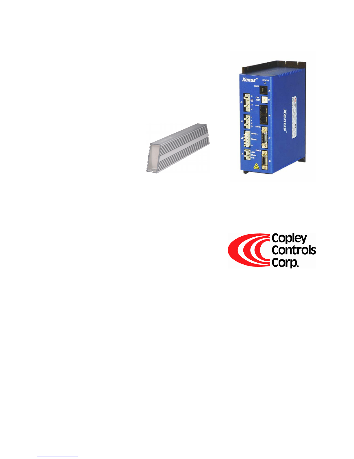
Xenus™ Regeneration Guide
P/N 95-00306-000
Revision 3
June 2008

Xenus Regeneration Guide
This page for notes.

TABLE OF CONTENTS
About This Guide..................................................................................................................................................................................iii
1: Regen Resistors for Xenus.........................................................................................................................................................1
A: Regen Resistor Sizing and Configuration ............................................................................................................................... 11
Overview and Scope............................................................................................................................................................iii
Related Documentation .......................................................................................................................................................iii
Comments...........................................................................................................................................................................iii
Copyrights ...........................................................................................................................................................................iii
Document Validity................................................................................................................................................................iii
Product Warnings............................................................................................................................................................... iv
Revision History.................................................................................................................................................................. iv
1.1: Regen Resistor Theory...........................................................................................................................................................2
1.2: Amplifier Regen Circuit Output Specifications ........................................................................................................................3
1.3: Copley Standard Regen Resistors..........................................................................................................................................4
1.3.1: Copley Standard Regen Resistor Dimensions ...........................................................................................................4
1.3.2: Copley Standard Regen Resistor Specifications........................................................................................................ 5
1.3.3: Copley Standard Regen Resistor Thermal Characteristics ........................................................................................5
1.4: Regen Circuit Wiring...............................................................................................................................................................6
1.4.1: Electrical Codes and Warnings..................................................................................................................................6
1.4.2: Amplifier Connector Locations ................................................................................................................................... 7
1.4.3: Regen Resistor (J3) Wiring........................................................................................................................................8
1.4.4: Regen Resistor Configuration with CME 2 ................................................................................................................. 9
A.1: Sizing a Regen Resistor.......................................................................................................................................................12
A.1.1: Gather Required Information ................................................................................................................................... 12
A.1.2: Observe the Properties of Each Deceleration During a Complete Cycle of Operation ............................................. 12
A.1.3: Calculate Energy Returned for Each Deceleration...................................................................................................13
A.1.4: Determine the Amount of Energy Dissipated by the Motor ...................................................................................... 13
A.1.5: Determine the Amount of Energy Returned to the Amplifier .................................................................................... 13
A.1.6: Determine if Energy Returned Exceeds Amplifier Capacity ..................................................................................... 14
A.1.7: Calculate Energy to be Dissipated for Each Deceleration........................................................................................ 14
A.1.8: Calculate Pulse Power of Each Deceleration that Exceeds Amplifier Capacity........................................................ 14
A.1.9: Calculate Resistance Needed to Dissipate the Pulse Power ................................................................................... 14
A.1.10: Calculate Continuous Power to be Dissipated ....................................................................................................... 15
A.1.11: Select Fuses ......................................................................................................................................................... 15
A.2: Configuring a Custom Regen Resistor ................................................................................................................................. 16
A.2.1: Regen Configuration Objective and Warning........................................................................................................... 16
A.2.2: Regen Configuration Instructions ............................................................................................................................ 16
Copley Controls Corp. i

Table of Contents Xenus Regeneration Guide
This page for notes.
ii Copley Controls Corp.

Overview and Scope
This guide describes the selection, installation, and configuration of external regen
resistors for Xenus Amplifiers.
Related Documentation
Users should also read these Copley Controls documents:
• Xenus User Guide
• CME 2 User Guide
Links to these publications, along with hardware manuals and data sheets, can be found
under the Documents heading of
http://www.copleycontrols.com/Motion/Downloads/index.html.
Information on Copley Controls Software can be found at:
http://www.copleycontrols.com/Motion/Products/Software/index.html
Comments
Copley Controls Corporation welcomes your comments on this guide. See
http://www.copleycontrols.com for contact information.
Copyrights
ABOUT THIS GUIDE
No part of this document may be reproduced in any form or by any means, electronic or
mechanical, including photocopying, without express written permission of Copley
Controls Corporation.
Xenus and CME 2 are registered trademarks of Copley Controls Corporation.
Document Validity
We reserve the right to modify our products. The information in this document is subject
to change without notice and does not represent a commitment by Copley Controls
Corporation. Copley Controls Corporation assumes no responsibility for any errors that
may appear in this document.
Copley Controls Corp. iii
About this Guide Xenus Regeneration Guide
Product Warnings
Observe all relevant state, regional, and local safety regulations when installing and using
this product. For safety and to assure compliance with documented system data, only
Copley Controls Corporation should perform repairs to amplifiers.
DANGER: Hazardous voltages.
Exercise caution when installing and adjusting.
!
DANGER
!
DANGER
!
DANGER
Failure to heed this warning can cause equipment damage, injury, or
death.
Risk of electric shock.
High-voltage circuits on J1, J2, and J3 are connected to mains power.
Failure to heed this warning can cause equipment damage, injury, or
death.
Use equipment as described.
Operate amplifiers within the specifications provided in this manual.
Failure to heed this warning can cause equipment damage, injury, or
death.
Revision History
Revision Date DECO # Comments
1.0 July 2003 Initial publication.
1.1 November
2004
2 February 2007 14988 Updated to describe new Copley regen resistor models.
3 June 2008 17137 Updated Web page references.
Corrected model number in specifications table (p. 5).
iv Copley Controls Corp.

CHAPTER
1: REGEN RESISTORS FOR XENUS
This chapter provides an overview of regeneration and using regen resistors with Xenus.
The contents of this chapter include:
Title Page
1.1: Regen Resistor Theory...........................................................................................................................................................2
1.2: Amplifier Regen Circuit Output Specifications ........................................................................................................................3
1.3: Copley Standard Regen Resistors..........................................................................................................................................4
1.4: Regen Circuit Wiring...............................................................................................................................................................6
Copley Controls Corp. 1

Regen Resistor Sizing and Configuration Xenus Regeneration Guide
1.1: Regen Resistor Theory
When a load is accelerated electrical energy is converted into mechanical energy. During
deceleration the conversion is reversed. This is called regeneration. Some of this
regenerated energy is lost to friction in the mechanical system. More of this energy is
converted to heat due to I
The remainder of the energy is added to the electrical energy already stored in the
internal capacitor bank of the amplifier. The result of this energy being added is an
increase in the voltage on the capacitor bank.
If too much energy is added to the capacitor bank, the voltage will rise to a point where
the amplifier's over voltage protection will shut down the amplifier. To prevent this, a
regen circuit shunts some of the energy into an external resistor, known as a regen
resistor, when the voltage rises too high.
Xenus provides an internal transistor that is used in combination with an external resistor.
Copley Controls supplies compatible external resistors. When using a resistor acquired
from another source, be sure it meets the specifications described in
Regen Resistor Sizing and Configuration (p. 11).
The amplifier protects the regen circuit against short circuit, and uses I
current/time algorithms to protect both the external resistor and internal transistor.
NOTE: The Xenus micro panel model has its own internal regen circuit and does not use
an external regen resistor.
2
R losses in the motor windings, cabling and drive electronics.
2
T peak
2 Copley Controls Corp.
 Loading...