

Copley Controls Corp. Actuator, ServoTube 38 Installation Manual

ServoTube 38
Copley
Controls
Corp.
Copley Motion Systems LLC
INSTALLATION GUIDE
Publication Ref: UM03013/A
Copley Motion Systems LLC
Luckyn Lane, Pipps Hill, Basildon, Essex SS14 3BW England
Tel: +44 (0)1268 287070 Fax +44 (0)1268 293344

Prelims ServoTube 38 Installation Guide
Copley
Controls
Corp.
Copley Motion Systems LLC
WARRANTY
Copley Motion Systems guarantees its equipment against faulty components for a period of twelve months from
delivery. Replacement components will be free of charge. Copley Motion Systems shall not in any event be liable for
consequential damage or loss.
Copley Motion Systems operates a customer care facility and all requests for repair and replacement should be
directed to the Customer Care Department. The serial number of the equipment should be quoted in any
communications. The right to change specification and price is reserved by Copley Motion Systems.
DISCLAIMER
Copley Motion Systems makes no guarantees of any kind with regard to this manual. Copley Motion Systems shall not
be liable for errors contained herein or for consequential or incidental damages incurred as a result of acting on
information contained in the manual.
CUSTOMER CARE
For enquiries relating to the operation and use of the ServoTube 38 described in this Manual please contact the
Customer Care Helpdesk, Telephone : +44 (0)1268 287070.
Copley Motion Systems LLC
Luckyn Lane, Pipps Hill, Basildon, Essex SS14 3BW England
Tel: +44 (0)1268 287070 Fax: +44 (0)1268 293344
ã Copley Motion Systems 2005
INTERNATIONAL CONTACT DETAILS
website: http//www.copleycontrols.com
Page (ii)
World Headquarters, USA
Copley Controls Corp.
20 Dan Road,
Canton,
MA 02021
USA
Tel: +1 781 828 8090
Fax: +1 781 828 1750
European Headquarters
Copley Motion Systems LLC
Luckyn Lane,
Pipps Hill,
Basildon, Essex SS14 3BW
England
Tel: +44 (0)1268 287070
Fax: +44 (0)1268 293344

ServoTube 38 Installation Guide Prelims
ServoTube 38
INSTALLATION GUIDE
Contents
Preliminary pages
Title page.............................................(i)
Copyright notice / disclaimer ..................................(ii)
Contents list (this page).....................................(iii)
Warnings ............................................(iv)
Cautions .............................................(v)
Reader’s Notes .........................................(vi)
Abbreviations ..........................................(vii)
Chapters
1 Overview ..........................................1
2 Installation .........................................3
3 Maintenance ........................................9
4 Service ..........................................11
Appendices
A Glossary of terms & Abbreviations ............................13
B Trouble Shooting .....................................17
C Technical Specification ..................................19
Page (iii)
Prelims ServoTube 38 Installation Guide
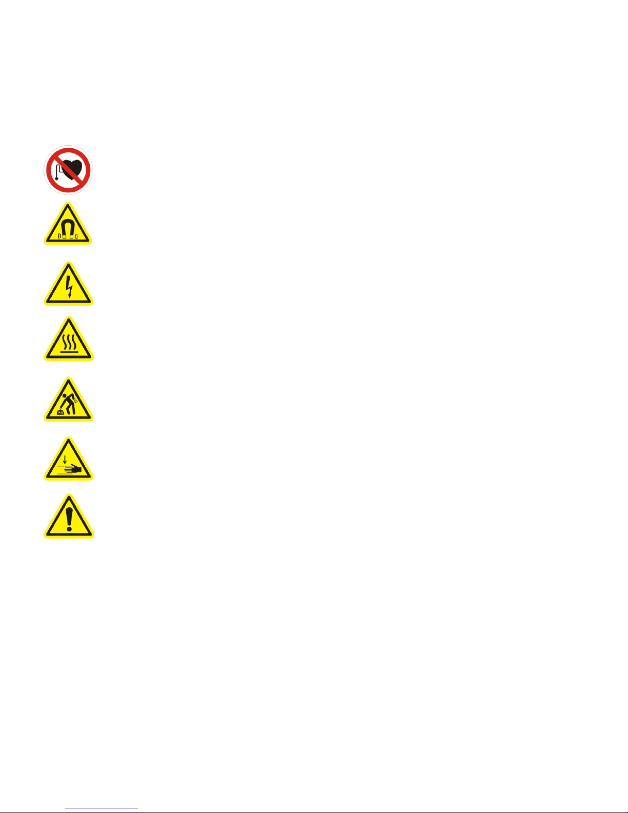
WARNINGS
Warning symbols and meanings
In this User Manual warning symbols are used. These are intended to alert you to the potential hazards to personnel
which are associated with the equipment described, in all aspects of use, including handling, installation, operation and
maintenance.
Heart pacemakers. Personnel fitted with pacemakers must not handle or work on this equipment.
Strong magnets. The thrust rod contains powerful magnets and will strongly attract ferrous objects.
Damage can occur to computer disks and credit cards.
Electric shock. Potentially lethal voltages may be present during the commissioning and servicing of
this equipment. Isolate and disconnect all sources of electrical supply before working on the
equipment. Particular care needs to be taken when working on or around motor phase connections.
Hot surface. Surface temperatures of up to 80 °C can be present during the commissioning and
servicing of this equipment. Allow the forcer and thrust rod to cool before working on the equipment.
Heavy object. May need two people to lift.
Crush hazard. The forcer may move unexpectedly. Always isolate all sources of electrical supply
before working on the equipment.
General hazard. Follow the advice given.
Electrical safety
This equipment must be earthed using the green/yellow conductor.
EMC precautions
This equipment is intended for use in a light industrial environment. It is recommended that the following precautions be
observed during installation:
Keep all cable lengths to a minimum.
•
Provide as much physical separation as possible between power and signal cables. In particular, avoid long,
•
parallel runs of cables.
Maintain screen continuity throughout the cable run.
•
Use 360 degree screen terminations where possible. “Pig-tail” terminations are not recommended.
•
It is the responsibility of the User to ensure compliance with any local electrical and EMC regulations in force at
•
the time of installation.
Page (iv)

ServoTube 38 Installation Guide Prelims
READER’S NOTES
GENERAL
This manual describes the Installation, Maintenance and Spares of the ServoTube 38 linear motor.
ASSOCIATED PUBLICATIONS
The following publications are associated with the ServoTube 38 User Manual.
Title Reference Number
ServoTube Applications Guide UM03012
XTA Data sheet DS01093
XTB Data sheet DS01094
Xenus User Guide -
Xenus Data Sheet -
Page (v)

Prelims ServoTube 38 Installation Guide
Page (vi)
ServoTube 38 Installation Guide Chapter 1
Overview
Chapter 1
Product Overview
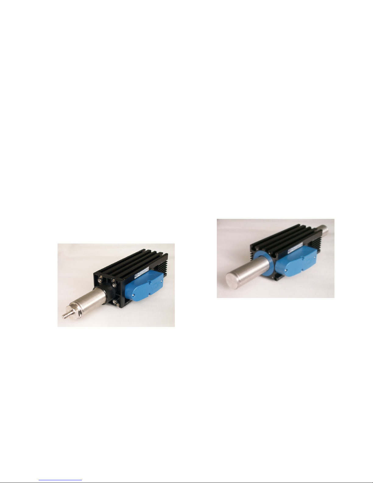
SERVOTUBE 38 ACTUATOR
The ServoTube 38 Actuator is an optimal solution
for industrial position control. Faster than a
ballscrew with the clean reliability of a linear motor,
the ServoTube 38 is a cost-effective alternative to
air cylinders in applications requiring greater
flexibility and control.
Four models
The ServoTube 38 Actuator incorporates an IP67 rated
forcer and a sealed stainless steel thrust rod enclosing
rare-earth magnets. Four models deliver a continuous
force range of 137-276 N (31-62 lb) with peak forces up
to 1860N (418 lb). Nine stroke lengths are available
from 33- 318 mm
The patented magnetic design of ServoTube 38
generates 25 micron (0.98 mil) repeatability and 400
micron (16 mil) accuracy from a non-contact, integral
position sensor. No external encoder is required.
Position output is industry standard 1V pk-pk sin/cos
signals.
model number and the system comes up tuned and
ready to run. Clear diagnostics make system
commissioning easy. Fill in the blanks to define position,
velocity and acceleration.
SERVOTUBE 38
ServoTube 38 delivers the speed of a belt-drive
system with the clean reliability of a linear motor at
a price unprecedented in the industry. Familiar
form factor, integral position feedback and large air
gap make installation simple.
The ServoTube 38 motor components comprise an
IP67 rated forcer and a sealed stainless steel thrust rod
enclosing rare-earth magnets. Four models deliver a
continuous force range of 137-276 N (31-62 lb) with
peak forces up to 1860 N (418 lb). A range of Thrust
Rods are available for travel lengths up to 1362 mm.
Figure 1.1 - ServoTube 38 Actuator
Maintenance free
The XTA has an internal dry bearing which provides a
clean, quiet, maintenance free performance. Life
expectancy far exceeds typical ballscrew solutions. The
ServoTube 38 Actuator is ideal for push/pull/lift material
handling, packaging and automated assembly
applications. ServoTube 38 accepts a range of industry
standard accessories for simple mechanical integration.
Plug and Play
Flexible mid-stroke position control is simple with Xenus
- a matched, self-tuning indexer complete with plugand-play cabling. Simply select your ServoTube 38
Figure 1.2 - ServoTube 38
The patented magnetic design of ServoTube 38
generates 25 micron (0.98 mil) repeatability and 400
micron (16 mil) accuracy from a non-contact, integral
position sensor. No external encoder is required.
Position output is industry standard 1V pk-pk sin/cos
signals.
Easy Integration
ServoTube 38 is an ideal OEM solution for easy
integration into pick-and-place gantries and general
purpose material handling machines. The load is
mounted directly to the Forcer typically supported by a
single bearing rail. The Thrust Rod is mounted at both
ends, similar to a ballscrew. A large air gap reduces
alignment constraints.
Page 1

Chapter 1 ServoTube 38 Installation Guide
Overview
The tubular motor has superior thermal efficiency,
radiating heat uniformly. High duty cycles are possible
without the need for forced-air or water cooling.
Amplifiers
ServoTube 38 is complemented by a range of matched,
self-tuning servo-amplifiers and indexers complete with
plug-and-play cabling. Amplifiers interface easily to
PLCs and feature CANopen network connectivity for
distributed control applications.
Page 2

ServoTube 38 Installation Guide ` Chapter 2
Installation
Chapter 2
Installation
UNPACKING
Check packaging for signs of damage.
•
Metal surfaces may be hot or below 0oC following prolonged storage.
•
Remove packaging. Do not discard. In the event of items requiring return, it is recommended that the original
•
packaging be used.
Ensure that the delivery note correctly reflects your order and the items delivered.
•
Check equipment for signs of damage. Never use the equipment if it appears damaged in any way.
•
Read the User Guide before installing and using this equipment.
•
INSTALLATION
Intended operating environment
This equipment is intended for use in an environment within the following conditions: -
Operating temperature 0 to +40 °C
Storage temperature -25 to +70 °C
Humidity (relative) 0 to 95% non-condensing
Altitude (above mean sea level) 1000 m
Overvoltage category II
Pollution degree 2
EMC light industrial
Page 3

Chapter 2 ServoTube 38 Installation Guide
Installation
Mechanical - XTA
The outline drawing of the XTA is shown in Figure 2.1. It comprises the forcer with an integrated plastic sleeve bearing
and the thrust rod. The integrated bearing acts as a guide for the moving thrust rod. It is not intended to withstand side
loading. If side loading is expected then it is advised that an external bearing is fitted.
The XTA forcer can be mounted by two methods.
• Using the T -slots in the top of the forcer.
• Using M6 fixings (4 off) on the end flange.
IMPORTANT
When using the end flange fixing method, the fixings and mounting plate must be of a non- ferrous material
such as aluminum, stainless steel, and plastic for example.
Dimensional details for both are given in Figure 2.1.
The recommended tightening torque for the fixings are:
M6 end flange 9 Nm M6 T-nut 10 Nm (both non lubricated i.e. no thread lock)
The thrust rod has optional male and female threaded connections at each end. These are intended to interface to a
number of standard accessories. The thrust rod has an external circlip at each end to restrain the thrust rod within the
forcer. These are not intended as "hard stops" to prevent over-travel and it is the responsibility of the User to prevent the
thrust rod from being ejected from the forcer.
Page 4
 Loading...