

Copley Controls Corp. 303, 303B, 306, 306AB, 312 User Manual
...
300 Series Amplifier
User’s Guide
Rev 08 5/00
All Rights Reserved
Models:
303,303B
306,306A,306B,306AB
312

The 300 Series Amplifier User’s Guide
Rev 07 9/96
All Rights Reserved

7
t,
7
s
Visit us on the web @ http://www.copleycontrols.com
Corporate Office, USA
410 University Ave.
Westwood, MA 02090
Tel: 617-329-8200
Fax: 617-329-4055
Central USA
Chicago, IL
Tel: 847-426-8793
Fax: 847-426-8789
West Coas
San Jose, C
Tel: 408-99
Fax: 408-99
e-mail:

300 Series Amplifier
User’s Guide
1996~1998 Copley Controls Corporation
410 University Avenue
Westwood, MA 02090
USA
All rights reserved
The 300 Series Amplifier User' s Guide Rev 08 5/00


300 SERIES USER GUIDE
Table of Contents
Table of Contents....................................................................................................................................... ii
A Visual Guide to the 300 family:............................................................................................................. iv
Introduction................................................................................................................................................1
Getting Started........................................................................................................................................... 1
Functional Diagram...................................................................................................................................2
J17 Component Header.............................................................................................................................. 3
Location....................................................................................................................................... 3
Current-Mode Setup (Standard configuration)............................................................................ 3
Velocity Mode Setup (Use components supplied)....................................................................... 3
Technical Specifications............................................................................................................................4
Mechanical Outlines.................................................................................................................................. 5
Basic Amplifier Connectors, Signals and Pinouts......................................................................................6
4 Pin power connector.................................................................................................................6
22 Pin signal connector................................................................................................................6
Basic Amplifier: Current-Mode, NO Tachometer .....................................................................................7
Amplifier Connections................................................................................................................. 7
Basic Amplifier: Current-Mode WITH Tachometer.................................................................................. 8
Amplifier Connections................................................................................................................. 8
Amplifier with MB4 Mounting Card: Current-Mode, NO Tachometer..................................................... 9
Amplifier Connections................................................................................................................. 9
Amplifier with MB4 Mounting Card: Current-Mode, WITH Tachometer............................................... 10
Amplifier Connections................................................................................................................. 10
Amplifier on Eurocard: Current-Mode, NO Tachometer........................................................................... 11
Amplifier Connections................................................................................................................. 11
Amplifier on Eurocard: Current-Mode, WITH Tachometer......................................................................12
Amplifier Connections................................................................................................................. 12
Power Supply Considerations.................................................................................................................... 13
Multiple Amplifier Power Connections....................................................................................... 13
Minimum Inductance................................................................................................................................. 14
Maximum Inductance ................................................................................................................................ 14
Bandwidth.................................................................................................................................................. 14
Enable Inputs............................................................................................................................................. 15
Current Monitor.........................................................................................................................................15
Status LED................................................................................................................................................. 15
Normal Output...........................................................................................................................................16
Reset Input.................................................................................................................................................16
Current Limit ............................................................................................................................................. 16
Output Voltage Swing................................................................................................................................16
DC Power Outputs.....................................................................................................................................17
Mounting....................................................................................................................................................18
Standard Mounting...................................................................................................................... 18
PC Board Mounting (-P option).................................................................................................. 18
MB4 Card Mounting ( -M option)...............................................................................................18
Eurocard Mounting (-E and -ER options)....................................................................................18
MB4 Mounting Card..................................................................................................................................19
Notes on Nomenclature............................................................................................................... 19
P1: 4 Pin power connector........................................................................................................... 19
P2: 15 Pin signal connector......................................................................................................... 19
Status Output............................................................................................................................... 19
Amplifier Signal Connector (J4).................................................................................................. 19
MB4 Card Options ......................................................................................................................20
Voltage-Mode (-V option) ............................................................................................20
IR-Comp (included with -V option).............................................................................. 20
PWM Inputs (-D option)............................................................................................... 20
Edge filters (-F option).................................................................................................. 20
MB4 Card Jumper Settings..........................................................................................................21
ii

300 SERIES USER GUIDE
Notes on Modes & Jumpers...........................................................................................21
Eurocard Mount.........................................................................................................................................22
DIN Connector Pinouts................................................................................................................22
Jumper Settings............................................................................................................................22
Status Output Jumper...................................................................................................................23
Tuning and Adjustments ............................................................................................................................23
Trimpots.......................................................................................................................................23
Balance..........................................................................................................................23
Feedback........................................................................................................................23
Current Limit.................................................................................................................23
Voltage Feedback..........................................................................................................23
IR Comp........................................................................................................................23
Mode Setting: Flat-Gain vs. Tachometer.....................................................................................24
Frequency Response with Tachometer.........................................................................................25
Tachometer Scaling.....................................................................................................................26
Voltage-Mode Gain.............................................................................................................. .......27
IR-Comp......................................................................................................................................28
Setup Procedure.............................................................................................................28
Static Setup Method ......................................................................................................28
Dynamic Setup Method.................................................................................................29
Notes on IR Compensation............................................................................................29
PWM Operation...........................................................................................................................30
Appendix....................................................................................................................................................31
Connector Part Numbers..............................................................................................................31
Basic Amplifier 4-pin power/motor connector................................................31
Basic Amplifier 22-pin signal connector (housing only).................................31
MB4 Card: 4 pin power/motor connector .......................................................31
MB4 Card: 15 pin signal connector (housing only) ........................................31
Pins for 15, 22 pin signal connector................................................................31
DIN backplane connector for Eurocard mount................................................31
References....................................................................................................................................31
Standard Power Supplies............................................................................................................31
MB4 Card Layout........................................................................................................................32
Eurocard Layout..........................................................................................................................33
Jumper Pin Numbering..................................................................................................33
Panel Layout..................................................................................................................33
MB4 Card Schematic...................................................................................................................34
Eurocard Schematic.....................................................................................................................35
Ordering Guide for 300 Series.....................................................................................................36
iii

300 SERIES USER GUIDE
A Visual Guide to the 300 family:
Basic Amplifier, No Mounting Card, No Heatsink (30x shown)
See p. 5 for connectors & pinouts.
See pp. 7-8 for wiring.
Amplifier with MB4 Mounting Card (30xPMFDV shown)
See p. 18 for connectors & pinouts.
See pp. 9-10 for wiring.
Amplifier on Eurocard Mount with Front Panel (30xER show n)
See p. 21 for connectors & pinouts.
See. pp. 11-12 for wiring.
iv

300 SERIES USER GUIDE
Introduction
The 300 Series amplifiers are second generation products designed for low cost and high
performance. They can be mounted on chassis or p.c. boards and operate from 16 to 160
volt single-output DC power supplies. A wide range of inductive loads can be driven:
64 uH to 50 mH depending on model and supply voltage.
All units feature fully differential inputs for the control, or reference voltage. Enable
inputs for output control, a status output, and a current monitor signal ease system
interfacing.
The 22 kHz . PWM switching frequency eliminates audible noise from moto r windings
and fast rise and fall times give high efficiency.
A Eurocard mount is available for 3U x 220 mm. rack mounting applications. A header
socket with plug-in components makes it easy to change compensation components for
different loads.
The amplifier is protected against over-temperature, over-voltage and under-voltage, and
output short circuits.
Getting Started
To install the amplifier you will need a control, or reference voltage, a power supply, and
a load. The reference voltage can be from something as simple as a potentiometer, or as
complex as a digital control system. The power supply can be supplied by the user, or
ordered from Copley Controls along with the amplifier to create a complete amplifier
subsystem. Loads are usually motors, but magnet coils, inductors, or other non-motor
loads can also be driven.
The amplifier is typically used as a voltage-to-current converter. ±10V reference signals
will drive the amplifier's peak rated current to the load in the 'flat-gain' mode. If a
tachometer is used, the amplifier is still operated as a voltage to current converter, but
the header components are changed to increase the gain of the servo preamplifier.
Use of the MB4 and Eurocard provides additional (optional) features such as voltagemode operation, armature-resistance(IR) compensation, PWM inputs, and output filters.
Eurocard mounts adapt the amplifiers to 3U subrack installations. Consult the factory for
Eurocard subrack systems.
1

300 SERIES USER GUIDE
Functional Diagram
2

300 SERIES USER GUIDE
J17 Component Header
This is an 11-position socket which holds resistors and capacitors which are used for
tachometer scaling and compensation, amplifier compensation, and current limiting.
Location
AMPLIFIER WITHOUT MB4 CARD
J17 HEADER
Current-Mode Setup (Standard configuration)
This is the standard configuration as delivered from the factory. In this mode, a voltage
at the reference inputs will force a current at the amplifier outputs. This is also called the
flat-gain mode because it provides the maximum bandwidth which remains constant over
the 3 kHz range.
Component
4-PIN
22-PIN
Value
Function as Shown
10 K
1
2
3
4
5
6
7
8
9
JP9
10
R10
11
R11
22
R1
R2
C3
C4
R5
C6
R7
R8
21
20
19
18
17
JUMPER
16
15
JUMPER
14
13
12
40.2 K
OPEN
330 pF
46.4 K
.01 uF
10 K
49.9 K
49.9 K
Not used in current-mode
Flat gain
Current Limit ; 10K = 100% of peak rated current
Enable polarity ; IN = Enable, OUT = Enable
Aux Input Gain
Ref Gain ; amplifier gain = Ipeak/10V
Notes:1. R1, R2, C3 and C6 have no function in current mode.
2. Current-limiting is non-linear with respect to R8. For best results, substitute 10K pot
for R8, adjust for desired current-limit, and replace with fixed resistor.
Velocity Mode Se tup (Use components supplied)
Use the components supplied in the brown bag to replace R5,R7, and C6. This will setup
the amplifier for use with tachometers. See Mode Setting for further details.
Component
1
2
3
4
5
6
7
8
9
10
11
R1
R2
C3
C4
R5
C6
R7
R8
JP9
R10
R11
22
21
20
19
18
17
16
15
14
13
12
Value
10 K
40.2 K
OPEN
330 pF
499 K
.01 uF
10 MEG
10 K
JUMPER
49.9 K
49.9 K
Function as Shown
Tach scaling ; 10V @ Ref = 8V @ Tach
(see Note 1 and Tachometer Scaling, p. 25)
Compensation (see Mode Setting section, p. 23)
Current Limit ; 10K = 100% of peak rated current
Enable polarity ; IN = Enable, OUT = Enable
Aux Input
Ref Gain ; servo preamp DC gain = 210
Notes:
1. R1, R2, and R11 interract to affect tachometer scaling and servo preamp gain.
2. Current-limiting is non-linear with respect to R8. For best results, substitute 10K pot
for R8, adjust for desired current-limit, and replace with fixed resistor.
3

300 SERIES USER GUIDE
Technical Specifications
4

300 SERIES USER GUIDE
Mechanical Outlines
5

300 SERIES USER GUIDE
Basic Amplifier
If you are using the MB4 or Eurocard, the pinouts will be different (refer to the sections
on the MB4 and Eurocard). Use this list when reading the following sections on hooking
up the basic amplifier.
Types of signals are listed after the pin number or letter.
P Passive Power and ground
I Input Analog or digital signal inputs
O Output Signal, logic, and power-stage outputs
Note: See appendix for complete listing of connectors and part-numbers.
4 Pin power connector
Type Remarks
AA
BB
CC
DD
22 Pin signal connector
Note that pins are referred to by letter and number. The letter refers to the functional
schematic. The number is the actual connector-pin number on the cable header that
connects to the amplifier.
Connectors, Signals and Pinouts
P +HV, the high-vol tage DC power input
O Out- , or negative output
O Out+, or positive output
P Ground and +HV power return
Table 1
-Pin- Type Signal Remarks
1 (A)
2 (B)
3 (C)
4 (D)
5 (E)
6 (F)
7 (G)
8 (H)
9 (I)
10 (J)
11 (K)
12 (L)
13 (M)
14 (N)
15 (O)
16 (P)
17 (Q)
18 (R)
19 (S)
20 (T)
21 (U)
22 (V)
I +Ref Differential (+) reference signal input
I -Ref " (-) " " "
P Signal Gnd Gnd for tachometer, signal gnd
O Ref amp out Output of differential input amplifier
I Aux input Auxiliary input
O
P Logic gnd Gnd for Enable inputs
O -11V 20K ohms in series with -11V
N.C. No connection to this pin
I /Reset LO or Gnd to reset fault condition
O Preamp out See schematic
Opt. ext. comp See schematic
I Tach input Tachometer input
Opt. ext. comp See schematic
I /Enable LO or Gnd to enable amplifier
I /Pos Enable LO or Gnd to enable positive output
I /Neg Enable LO or Gnd to enable negative output
O +14V 1K ohms in series with +14V
O Normal HI (+5V) when amplifier operating Normally
O +5V 2.49K in series with internal +5V
N.C.
O Current monitor Outputs +/-6V at amplifier peak current
20K ohms in series with +11V
+11V
Table 2
6
300 SERIES USER GUIDE
Basic Amplifier
Use this checklist for applications that don't employ a tachometer. These include
1. Connect DC power supply to amplifier +HV and GND. Check voltage to see that is is
2. Ground amplifier to chassis at GND pin DD.
3. Connect motor or load between OUT+ and OUT-. Do not ground load!
4. Connect reference voltage source to REF+ and REF- inputs.
5. Ground ENABLE,POS ENABLE, NEG ENABLE to amplifier logic ground.
6. Set FEEDBACK pot to full CW.
7. Set V
8. Turn power on
9. Check for green LED indicating Normal operation.
10. Adjust BALANCE trimpot for 0.0V between OUT+ and OUT-
11. Momentarily increase Reference voltage (±10V max).
12. Check motor direction: is it OK?
13. Set Reference voltage to maximum value (+/-10V)
14. Check load current at CURRENT MONITOR output
15. Apply step or square-wave signal to Ref-inputs, adjust FEEDBACK CCW for
: Current-Mode,
NO Tachometer
microprocessor control systems that get position feedback from an encoder on the
motor, as well as non-motor applications such as magnet-coil, solenoids, or other loads
that require a set current from the amplifier in response to a control-voltage at the
inputs. The components on the J17 header come from the factory preset for this
operating mode. See functional diagram on page 2.
within the amplifiers' rating.
to 0V
ref
YES: continue
NO: remove power, reverse connections to Ref+ and Ref-.
best response with no oscillation.
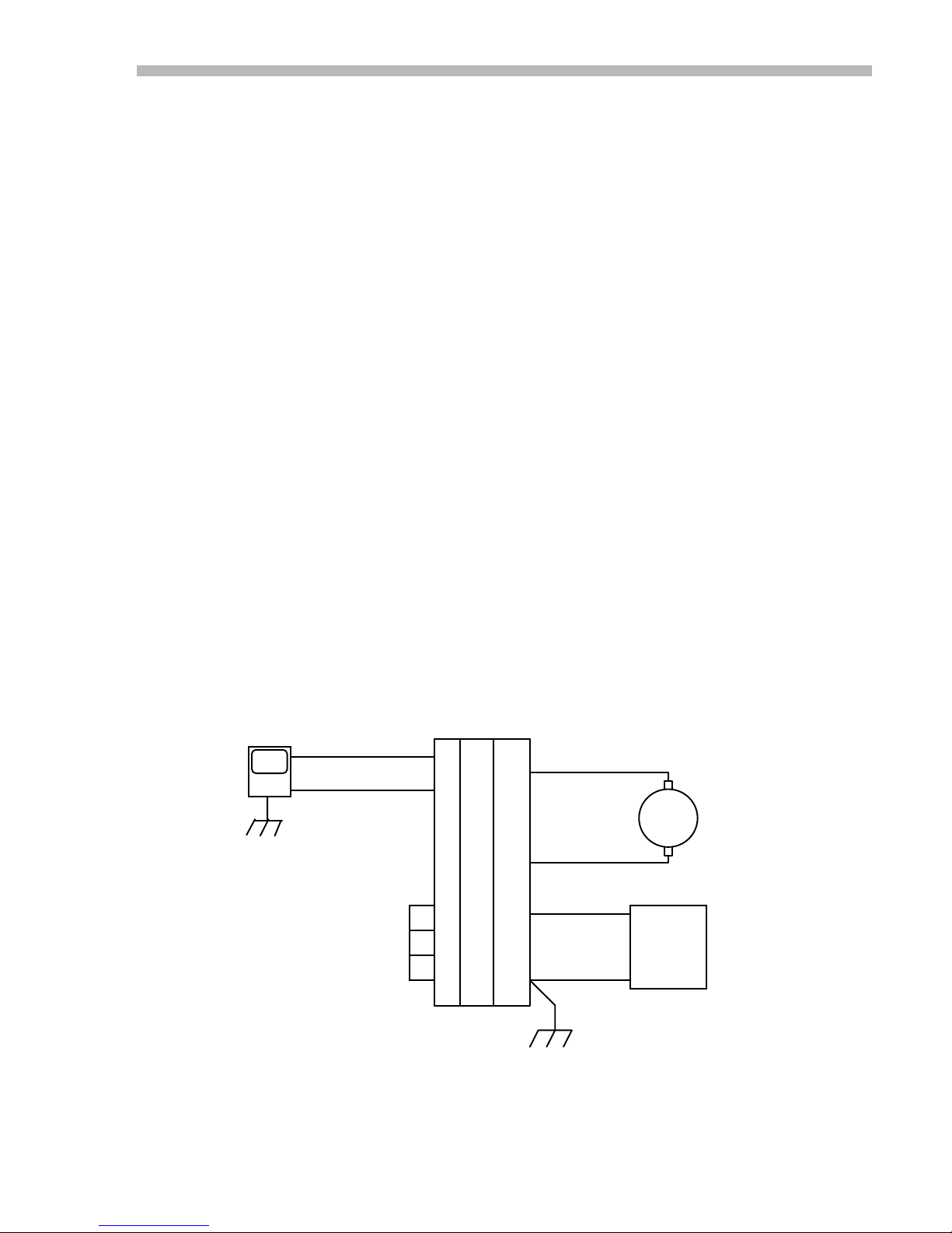
Amplifier Connections
Numbered terminals are on the brown 22-pin connector. Double-letter terminals are on
the orange 4-pin connector. See appendix for connector part numbers.
CONTROLLER
OUT
GND
ENABLE
POS ENABLE
NEG ENABLE
LOGIC GND
REF+
REF-
AMPLIFIER
22-Pin 4-Pin
1
CC
2
BB
15
AA
16
17
7
DD
Fig. 1
OUT+
OUT-
+HV
GND
CHASSIS GND
MOTOR
+
DC
POWER
SUPPLY
-
7
 Loading...