

Page 1

300 Series Amplifier
User’s Guide
Rev 08 5/00
All Rights Reserved
Models:
303,303B
306,306A,306B,306AB
312
Page 2

The 300 Series Amplifier User’s Guide
Rev 07 9/96
All Rights Reserved
Page 3

7
t,
7
s
Visit us on the web @ http://www.copleycontrols.com
Corporate Office, USA
410 University Ave.
Westwood, MA 02090
Tel: 617-329-8200
Fax: 617-329-4055
Central USA
Chicago, IL
Tel: 847-426-8793
Fax: 847-426-8789
West Coas
San Jose, C
Tel: 408-99
Fax: 408-99
e-mail:
Page 4

300 Series Amplifier
User’s Guide
1996~1998 Copley Controls Corporation
410 University Avenue
Westwood, MA 02090
USA
All rights reserved
The 300 Series Amplifier User' s Guide Rev 08 5/00
Page 5

Page 6

300 SERIES USER GUIDE
Table of Contents
Table of Contents....................................................................................................................................... ii
A Visual Guide to the 300 family:............................................................................................................. iv
Introduction................................................................................................................................................1
Getting Started........................................................................................................................................... 1
Functional Diagram...................................................................................................................................2
J17 Component Header.............................................................................................................................. 3
Location....................................................................................................................................... 3
Current-Mode Setup (Standard configuration)............................................................................ 3
Velocity Mode Setup (Use components supplied)....................................................................... 3
Technical Specifications............................................................................................................................4
Mechanical Outlines.................................................................................................................................. 5
Basic Amplifier Connectors, Signals and Pinouts......................................................................................6
4 Pin power connector.................................................................................................................6
22 Pin signal connector................................................................................................................6
Basic Amplifier: Current-Mode, NO Tachometer .....................................................................................7
Amplifier Connections................................................................................................................. 7
Basic Amplifier: Current-Mode WITH Tachometer.................................................................................. 8
Amplifier Connections................................................................................................................. 8
Amplifier with MB4 Mounting Card: Current-Mode, NO Tachometer..................................................... 9
Amplifier Connections................................................................................................................. 9
Amplifier with MB4 Mounting Card: Current-Mode, WITH Tachometer............................................... 10
Amplifier Connections................................................................................................................. 10
Amplifier on Eurocard: Current-Mode, NO Tachometer........................................................................... 11
Amplifier Connections................................................................................................................. 11
Amplifier on Eurocard: Current-Mode, WITH Tachometer......................................................................12
Amplifier Connections................................................................................................................. 12
Power Supply Considerations.................................................................................................................... 13
Multiple Amplifier Power Connections....................................................................................... 13
Minimum Inductance................................................................................................................................. 14
Maximum Inductance ................................................................................................................................ 14
Bandwidth.................................................................................................................................................. 14
Enable Inputs............................................................................................................................................. 15
Current Monitor.........................................................................................................................................15
Status LED................................................................................................................................................. 15
Normal Output...........................................................................................................................................16
Reset Input.................................................................................................................................................16
Current Limit ............................................................................................................................................. 16
Output Voltage Swing................................................................................................................................16
DC Power Outputs.....................................................................................................................................17
Mounting....................................................................................................................................................18
Standard Mounting...................................................................................................................... 18
PC Board Mounting (-P option).................................................................................................. 18
MB4 Card Mounting ( -M option)...............................................................................................18
Eurocard Mounting (-E and -ER options)....................................................................................18
MB4 Mounting Card..................................................................................................................................19
Notes on Nomenclature............................................................................................................... 19
P1: 4 Pin power connector........................................................................................................... 19
P2: 15 Pin signal connector......................................................................................................... 19
Status Output............................................................................................................................... 19
Amplifier Signal Connector (J4).................................................................................................. 19
MB4 Card Options ......................................................................................................................20
Voltage-Mode (-V option) ............................................................................................20
IR-Comp (included with -V option).............................................................................. 20
PWM Inputs (-D option)............................................................................................... 20
Edge filters (-F option).................................................................................................. 20
MB4 Card Jumper Settings..........................................................................................................21
ii
Page 7

300 SERIES USER GUIDE
Notes on Modes & Jumpers...........................................................................................21
Eurocard Mount.........................................................................................................................................22
DIN Connector Pinouts................................................................................................................22
Jumper Settings............................................................................................................................22
Status Output Jumper...................................................................................................................23
Tuning and Adjustments ............................................................................................................................23
Trimpots.......................................................................................................................................23
Balance..........................................................................................................................23
Feedback........................................................................................................................23
Current Limit.................................................................................................................23
Voltage Feedback..........................................................................................................23
IR Comp........................................................................................................................23
Mode Setting: Flat-Gain vs. Tachometer.....................................................................................24
Frequency Response with Tachometer.........................................................................................25
Tachometer Scaling.....................................................................................................................26
Voltage-Mode Gain.............................................................................................................. .......27
IR-Comp......................................................................................................................................28
Setup Procedure.............................................................................................................28
Static Setup Method ......................................................................................................28
Dynamic Setup Method.................................................................................................29
Notes on IR Compensation............................................................................................29
PWM Operation...........................................................................................................................30
Appendix....................................................................................................................................................31
Connector Part Numbers..............................................................................................................31
Basic Amplifier 4-pin power/motor connector................................................31
Basic Amplifier 22-pin signal connector (housing only).................................31
MB4 Card: 4 pin power/motor connector .......................................................31
MB4 Card: 15 pin signal connector (housing only) ........................................31
Pins for 15, 22 pin signal connector................................................................31
DIN backplane connector for Eurocard mount................................................31
References....................................................................................................................................31
Standard Power Supplies............................................................................................................31
MB4 Card Layout........................................................................................................................32
Eurocard Layout..........................................................................................................................33
Jumper Pin Numbering..................................................................................................33
Panel Layout..................................................................................................................33
MB4 Card Schematic...................................................................................................................34
Eurocard Schematic.....................................................................................................................35
Ordering Guide for 300 Series.....................................................................................................36
iii
Page 8

300 SERIES USER GUIDE
A Visual Guide to the 300 family:
Basic Amplifier, No Mounting Card, No Heatsink (30x shown)
See p. 5 for connectors & pinouts.
See pp. 7-8 for wiring.
Amplifier with MB4 Mounting Card (30xPMFDV shown)
See p. 18 for connectors & pinouts.
See pp. 9-10 for wiring.
Amplifier on Eurocard Mount with Front Panel (30xER show n)
See p. 21 for connectors & pinouts.
See. pp. 11-12 for wiring.
iv
Page 9

300 SERIES USER GUIDE
Introduction
The 300 Series amplifiers are second generation products designed for low cost and high
performance. They can be mounted on chassis or p.c. boards and operate from 16 to 160
volt single-output DC power supplies. A wide range of inductive loads can be driven:
64 uH to 50 mH depending on model and supply voltage.
All units feature fully differential inputs for the control, or reference voltage. Enable
inputs for output control, a status output, and a current monitor signal ease system
interfacing.
The 22 kHz . PWM switching frequency eliminates audible noise from moto r windings
and fast rise and fall times give high efficiency.
A Eurocard mount is available for 3U x 220 mm. rack mounting applications. A header
socket with plug-in components makes it easy to change compensation components for
different loads.
The amplifier is protected against over-temperature, over-voltage and under-voltage, and
output short circuits.
Getting Started
To install the amplifier you will need a control, or reference voltage, a power supply, and
a load. The reference voltage can be from something as simple as a potentiometer, or as
complex as a digital control system. The power supply can be supplied by the user, or
ordered from Copley Controls along with the amplifier to create a complete amplifier
subsystem. Loads are usually motors, but magnet coils, inductors, or other non-motor
loads can also be driven.
The amplifier is typically used as a voltage-to-current converter. ±10V reference signals
will drive the amplifier's peak rated current to the load in the 'flat-gain' mode. If a
tachometer is used, the amplifier is still operated as a voltage to current converter, but
the header components are changed to increase the gain of the servo preamplifier.
Use of the MB4 and Eurocard provides additional (optional) features such as voltagemode operation, armature-resistance(IR) compensation, PWM inputs, and output filters.
Eurocard mounts adapt the amplifiers to 3U subrack installations. Consult the factory for
Eurocard subrack systems.
1
Page 10

300 SERIES USER GUIDE
Functional Diagram
2
Page 11

300 SERIES USER GUIDE
J17 Component Header
This is an 11-position socket which holds resistors and capacitors which are used for
tachometer scaling and compensation, amplifier compensation, and current limiting.
Location
AMPLIFIER WITHOUT MB4 CARD
J17 HEADER
Current-Mode Setup (Standard configuration)
This is the standard configuration as delivered from the factory. In this mode, a voltage
at the reference inputs will force a current at the amplifier outputs. This is also called the
flat-gain mode because it provides the maximum bandwidth which remains constant over
the 3 kHz range.
Component
4-PIN
22-PIN
Value
Function as Shown
10 K
1
2
3
4
5
6
7
8
9
JP9
10
R10
11
R11
22
R1
R2
C3
C4
R5
C6
R7
R8
21
20
19
18
17
JUMPER
16
15
JUMPER
14
13
12
40.2 K
OPEN
330 pF
46.4 K
.01 uF
10 K
49.9 K
49.9 K
Not used in current-mode
Flat gain
Current Limit ; 10K = 100% of peak rated current
Enable polarity ; IN = Enable, OUT = Enable
Aux Input Gain
Ref Gain ; amplifier gain = Ipeak/10V
Notes:1. R1, R2, C3 and C6 have no function in current mode.
2. Current-limiting is non-linear with respect to R8. For best results, substitute 10K pot
for R8, adjust for desired current-limit, and replace with fixed resistor.
Velocity Mode Se tup (Use components supplied)
Use the components supplied in the brown bag to replace R5,R7, and C6. This will setup
the amplifier for use with tachometers. See Mode Setting for further details.
Component
1
2
3
4
5
6
7
8
9
10
11
R1
R2
C3
C4
R5
C6
R7
R8
JP9
R10
R11
22
21
20
19
18
17
16
15
14
13
12
Value
10 K
40.2 K
OPEN
330 pF
499 K
.01 uF
10 MEG
10 K
JUMPER
49.9 K
49.9 K
Function as Shown
Tach scaling ; 10V @ Ref = 8V @ Tach
(see Note 1 and Tachometer Scaling, p. 25)
Compensation (see Mode Setting section, p. 23)
Current Limit ; 10K = 100% of peak rated current
Enable polarity ; IN = Enable, OUT = Enable
Aux Input
Ref Gain ; servo preamp DC gain = 210
Notes:
1. R1, R2, and R11 interract to affect tachometer scaling and servo preamp gain.
2. Current-limiting is non-linear with respect to R8. For best results, substitute 10K pot
for R8, adjust for desired current-limit, and replace with fixed resistor.
3
Page 12

300 SERIES USER GUIDE
Technical Specifications
4
Page 13

300 SERIES USER GUIDE
Mechanical Outlines
5
Page 14

300 SERIES USER GUIDE
Basic Amplifier
If you are using the MB4 or Eurocard, the pinouts will be different (refer to the sections
on the MB4 and Eurocard). Use this list when reading the following sections on hooking
up the basic amplifier.
Types of signals are listed after the pin number or letter.
P Passive Power and ground
I Input Analog or digital signal inputs
O Output Signal, logic, and power-stage outputs
Note: See appendix for complete listing of connectors and part-numbers.
4 Pin power connector
Type Remarks
AA
BB
CC
DD
22 Pin signal connector
Note that pins are referred to by letter and number. The letter refers to the functional
schematic. The number is the actual connector-pin number on the cable header that
connects to the amplifier.
Connectors, Signals and Pinouts
P +HV, the high-vol tage DC power input
O Out- , or negative output
O Out+, or positive output
P Ground and +HV power return
Table 1
-Pin- Type Signal Remarks
1 (A)
2 (B)
3 (C)
4 (D)
5 (E)
6 (F)
7 (G)
8 (H)
9 (I)
10 (J)
11 (K)
12 (L)
13 (M)
14 (N)
15 (O)
16 (P)
17 (Q)
18 (R)
19 (S)
20 (T)
21 (U)
22 (V)
I +Ref Differential (+) reference signal input
I -Ref " (-) " " "
P Signal Gnd Gnd for tachometer, signal gnd
O Ref amp out Output of differential input amplifier
I Aux input Auxiliary input
O
P Logic gnd Gnd for Enable inputs
O -11V 20K ohms in series with -11V
N.C. No connection to this pin
I /Reset LO or Gnd to reset fault condition
O Preamp out See schematic
Opt. ext. comp See schematic
I Tach input Tachometer input
Opt. ext. comp See schematic
I /Enable LO or Gnd to enable amplifier
I /Pos Enable LO or Gnd to enable positive output
I /Neg Enable LO or Gnd to enable negative output
O +14V 1K ohms in series with +14V
O Normal HI (+5V) when amplifier operating Normally
O +5V 2.49K in series with internal +5V
N.C.
O Current monitor Outputs +/-6V at amplifier peak current
20K ohms in series with +11V
+11V
Table 2
6
Page 15
300 SERIES USER GUIDE
Basic Amplifier
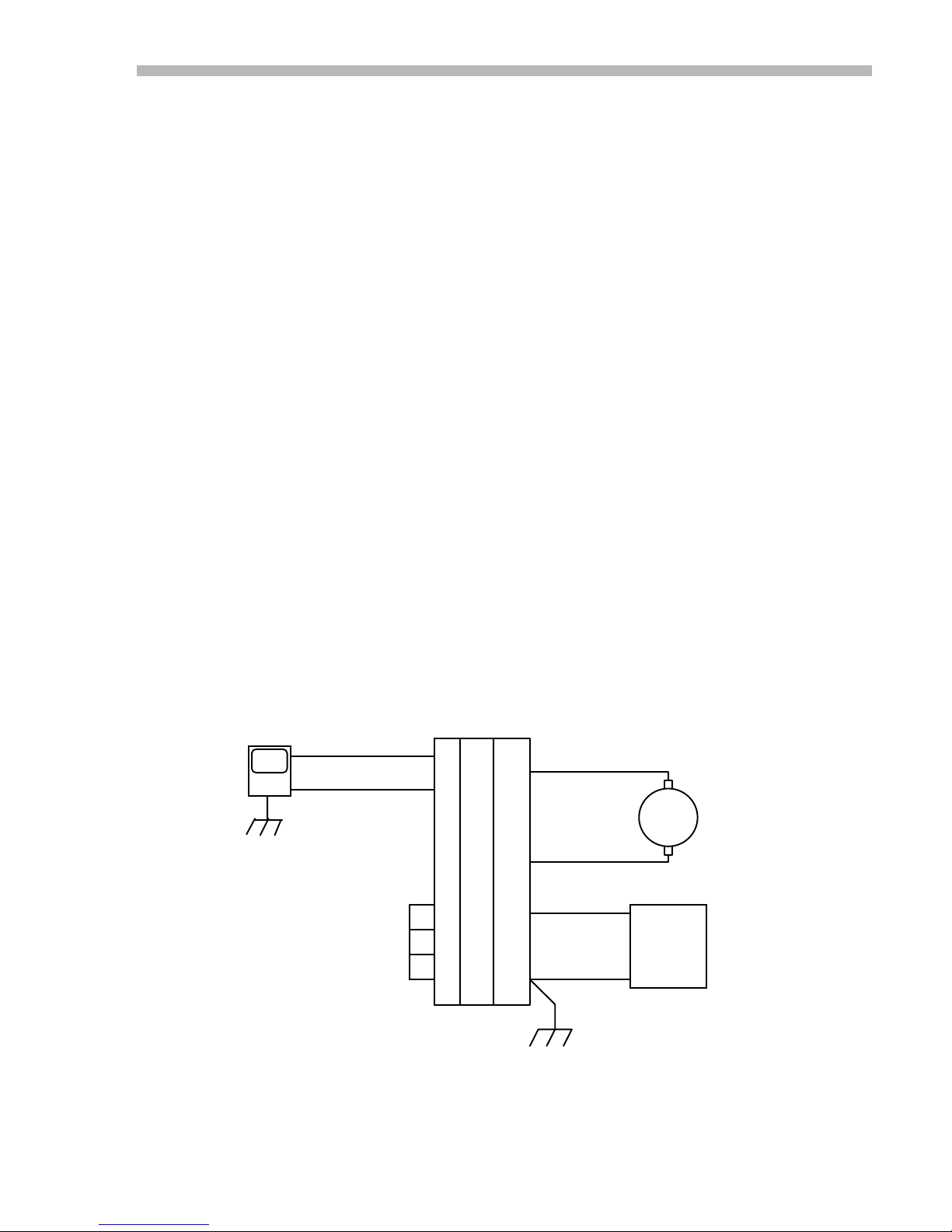
Use this checklist for applications that don't employ a tachometer. These include
1. Connect DC power supply to amplifier +HV and GND. Check voltage to see that is is
2. Ground amplifier to chassis at GND pin DD.
3. Connect motor or load between OUT+ and OUT-. Do not ground load!
4. Connect reference voltage source to REF+ and REF- inputs.
5. Ground ENABLE,POS ENABLE, NEG ENABLE to amplifier logic ground.
6. Set FEEDBACK pot to full CW.
7. Set V
8. Turn power on
9. Check for green LED indicating Normal operation.
10. Adjust BALANCE trimpot for 0.0V between OUT+ and OUT-
11. Momentarily increase Reference voltage (±10V max).
12. Check motor direction: is it OK?
13. Set Reference voltage to maximum value (+/-10V)
14. Check load current at CURRENT MONITOR output
15. Apply step or square-wave signal to Ref-inputs, adjust FEEDBACK CCW for
: Current-Mode,
NO Tachometer
microprocessor control systems that get position feedback from an encoder on the
motor, as well as non-motor applications such as magnet-coil, solenoids, or other loads
that require a set current from the amplifier in response to a control-voltage at the
inputs. The components on the J17 header come from the factory preset for this
operating mode. See functional diagram on page 2.
within the amplifiers' rating.
to 0V
ref
YES: continue
NO: remove power, reverse connections to Ref+ and Ref-.
best response with no oscillation.
Amplifier Connections
Numbered terminals are on the brown 22-pin connector. Double-letter terminals are on
the orange 4-pin connector. See appendix for connector part numbers.
CONTROLLER
OUT
GND
ENABLE
POS ENABLE
NEG ENABLE
LOGIC GND
REF+
REF-
AMPLIFIER
22-Pin 4-Pin
1
CC
2
BB
15
AA
16
17
7
DD
Fig. 1
OUT+
OUT-
+HV
GND
CHASSIS GND
MOTOR
+
DC
POWER
SUPPLY
-
7
Page 16
300 SERIES USER GUIDE
Basic Amplifier:
1. Setup J17 header components for high gain, tachometer mode (see p.3)
2. Connect DC power supply to amplifier +HV and GND. Check voltage to see that is
3. Ground amplifier to chassis at GND pin DD.
4. Connect motor or load between OUT+ and OUT-. Do not ground load!
5. Connect reference voltage source to REF+ and REF- inputs.
6. Connect Tachometer between tach input and signal ground.
7. Ground ENABLE,POS ENABLE, NEG ENABLE to amplifier logic ground.
8. Set FEEDBACK pot to full CW.
9. Set
10. Turn power on.
11. Does the motor run away?:
12. Check for green LED indicating Normal operation.
13. Adjust BALANCE trimpot for 0.0V between OUT+ and OUT-
14. Momentarily increase Reference voltage (±10V max).
15. Check motor direction: is it OK?
16. Set Reference voltage to maximum value (+/-10V)
17. Check load current at CURRENT MONITOR output
18. Adjust CURRENT LIMIT trimpot for desired maximum current.
19. Set Reference voltage to zero, turn feedback trimpot CCW until oscillation begins
20. Apply step or square-wave signal to Ref-inputs, adjust FEEDB ACK CCW for best
Current-Mode
WITH Tachometer
within the amplifiers' rating.
to 0V
VREF
YES: remove power, reverse tachometer leads
NO: continue
YES: continue
NO: remove power, reverse connections to Ref+ and Ref-.
(audible squeal or noise). Back-off two turns CW or until oscillation stops.
response with no oscillation.
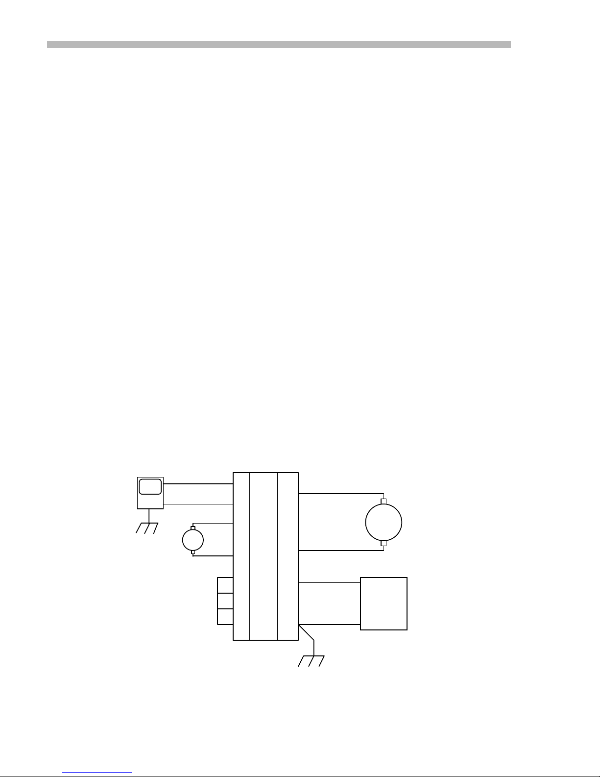
Amplifier Connections
Single-letter terminals are on the brown 22-pin connector. Double-letter terminals are on
the orange 4-pin connector.
CONTROLLER
REF+
REF-
TACH
ENABLE
POS ENABLE
NEG ENABLE
LOGIC GND
AMPLIFIER
22-Pin
1
2
13
-
+
3
15
16
17
7
4-Pin
CC
BB
AA
DD
Fig. 2
OUT+
OUT-
+HV
+
GND
CHASSIS GND
-
+
MOTOR
-
DC
POWER
SUPPLY
8
Page 17
300 SERIES USER GUIDE
Amplifier with MB4 Mounting Card
Use this checklist for applications that don't employ a tachometer. These include
microprocessor control systems that get position feedback from an encoder on the
motor, as well as non-motor applications such as magnet-coil, solenoids, or other loads
that require a set current from the amplifier in response to a control-voltage at the
inputs. The components on the J17 header come from the factory preset for this
operating mode. See functional diagram on page 2.
1. Connect DC power supply to MB4 card P1 (see diagram below). Check voltage to
see that is is within the amplifiers' rating.
2. Ground MB4 card to chassis at pin P1-4.
3. Connect motor or load between OUT+ and OUT-. Do not ground load!
4. Connect reference voltage source to REF+ and REF- inputs.
5. Ground ENABLE,POS ENABLE, NEG ENABLE to amplifier logic ground.
6. Set REF GAIN pot to full CW.
7. Set FEEDBACK pot to full CW.
8. Set CURRENT LIMIT pot to full CW.
9. Set V
10. Turn power on
11. Check for green LED indicating Normal operation.
12. Adjust BALANCE trimpot for 0.0V between OUT+ and OUT-
13. Momentarily increase Reference voltage (±10V max).
14. Check motor direction: is it OK?
15. Set Reference voltage to maximum value (+/-10V)
16. Check load current at CURRENT MONITOR output
17. Apply step or square-wave signal to Re f-inputs, adjust FEEDBACK CCW for be st
to 0V
ref
YES: continue
NO: remove power, reverse connections to Ref+ and Ref-.
response with no oscillation.
: Current-Mode,
NO Tachometer
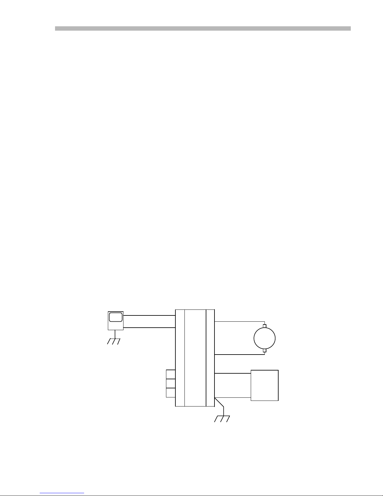
Amplifier Connections
Numbered terminals are on the brown 15-pin connector(P2). Double-letter terminals are
on the orange 4-pin connector(P1). See appendix for connector part numbers.
CONTROLLER
OUT
GND
ENABLE
POS ENABLE
NEG ENABLE
LOGIC GND
REF+
REF-
MB4 Card
P2
8
15
3
2
1
11
P1
Fig. 3
3
2
1
4
OUT+
OUT-
+HV
GND
CHASSIS GND
MOTOR
+
DC
POWER
SUPPLY
-
9
Page 18
300 SERIES USER GUIDE
Amplifier with MB4 Mounting Card
WITH Tachometer
Use this checklist for applications that do employ a tachometer. These include
microprocessor control systems that get position feedback from an encoder on the
motor, as well as non-motor applications such as magnet-coil, solenoids, or other loads
that require a set current from the amplifier in response to a control-voltage at the
inputs. The components on the J17 header come from the factory preset for this
operating mode. See functional diagram on page 2.
1. Connect DC power supply to MB4 card P1 (see diagram below). Check voltage to
see that is is within the amplifiers' rating.
2. Ground amplifier to chassis at pin P1-4.
3. Connect motor or load between OUT+ and OUT-. Do not ground load!
4. Connect reference voltage source to REF+ and REF- inputs.
5. Ground ENABLE,POS ENABLE, NEG ENABLE to amplifier logic ground.
6. Set REF GAIN pot to full CW.
7. Set FEEDBACK pot to full CW.
8. Set CURRENT LIMIT pot to full CW.
9. Set V
10. Turn power on
11. Check for green LED indicating Normal operation.
12. Adjust BALANCE trimpot for 0.0V between OUT+ and OUT-
13. Momentarily increase Reference voltage (±10V max).
14. Check motor direction: is it OK?
15. Set Reference voltage to maximum value (+/-10V)
16. Check load current at CURRENT MONITOR output
17. Apply step or square-wave signal to Re f-inputs, adjust FEEDBACK CCW for be st
to 0V
ref
YES: continue
NO: remove power, reverse connections to Ref+ and Ref-.
response with no oscillation.
: Current-Mode,
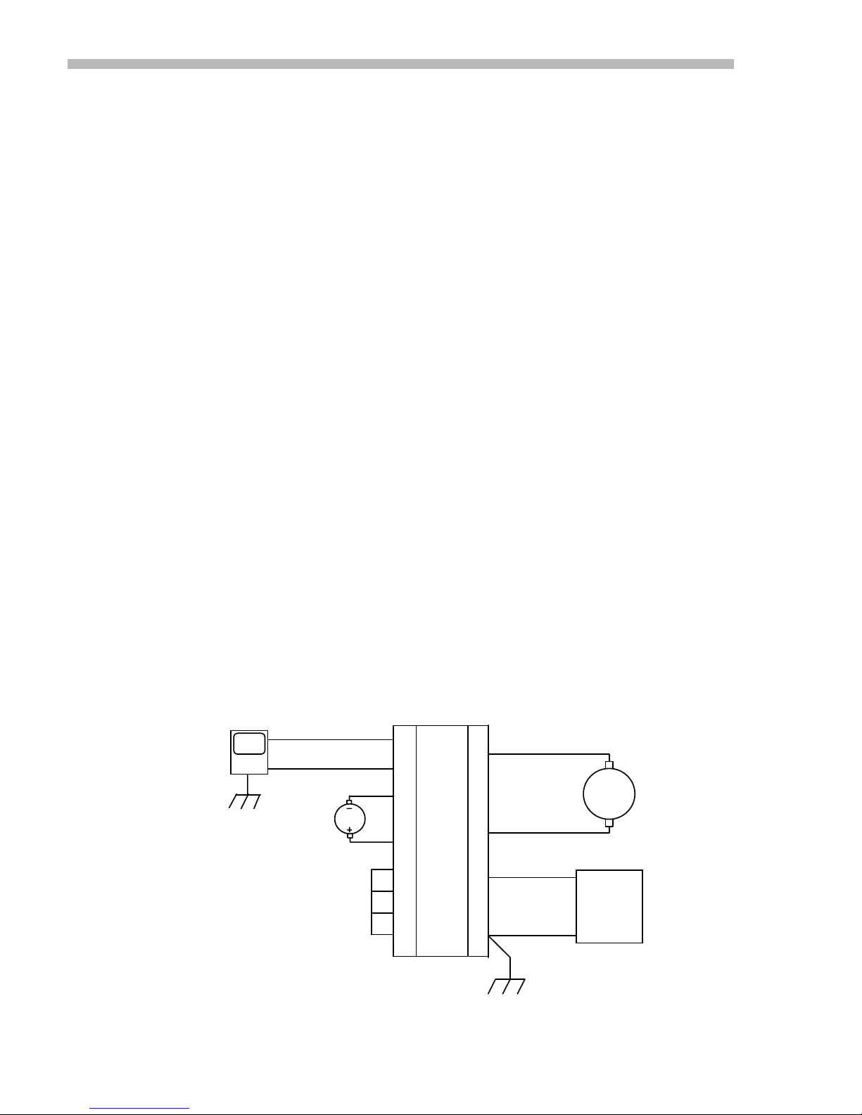
Amplifier Connections
Numbered terminals are on the brown 15-pin connector. Double-letter terminals are on
the orange 4-pin connector. See appendix for connector part numbers.
CONTROLLER
OUT
GND
TACH
ENABLE
POS ENABLE
NEG ENABLE
LOGIC GND
REF+
REF-
MB4 Card
P2
8
15
6
14
3
2
1
11
Fig. 4
1
P1
3
2
4
OUT+
OUT-
+HV
GND
CHASSIS GND
MOTOR
+
DC
POWER
SUPPLY
-
10
Page 19
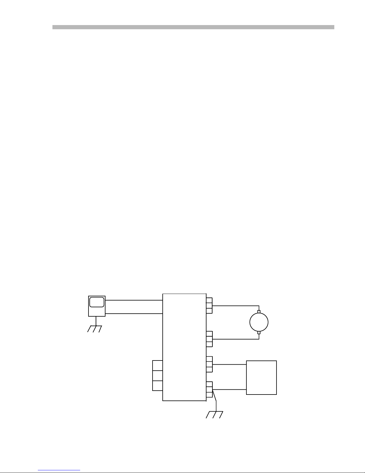
300 SERIES USER GUIDE
Amplifier on Eurocard:
Use this checklist for applications that don't employ a tachometer. These include
microprocessor control systems that get position feedback from an encoder on the
motor, as well as non-motor applications such as magnet-coil, solenoids, or other loads
that require a set current from the amplifier in response to a control-voltage at the
inputs. The components on the J17 header come from the factory preset for this
operating mode. See functional diagram on page 2.
1. Connect DC power supply to amplifier +HV and GND. Check voltage to see that is is
within the amplifiers' rating.
2. Ground amplifier to chassis at GND pin DD.
3. Connect motor or load between OUT+ and OUT-. Do not ground load!
4. Connect reference voltage source to REF+ and REF- inputs.
5. Ground ENABLE,POS ENABLE, NEG ENABLE to amplifier logic ground.
6. Set REF GAIN pot to full CW.
7. Set FEEDBACK pot to full CW.
8. Set CURRENT LIMIT pot to full CW.
9. Set V
10. Turn power on
11. Check for green LED indicating Normal operation.
12. Adjust BALANCE trimpot for 0.0V between OUT+ and OUT-
13. Momentarily increase Reference voltage (±10V max).
14. Check motor direction: is it OK?
15. Set Reference voltage to maximum value (+/-10V)
16. Check load current at CURRENT MONITOR output
17. Apply step or square-wave signal to Re f-inputs, adjust FEEDBACK CCW for be st
to 0V
ref
YES: continue
NO: remove power, reverse connections to Ref+ and Ref-.
response with no oscillation.
Current-Mode,
NO Tachometer
Amplifier Connections
Numbered terminals are on the brown 15-pin connector. Double-letter terminals are on
the orange 4-pin connector. See appendix for connector part numbers.
AMPLIFIER
CONTROLLER
OUT
GND
REF+
REF-
+ Eurocard
C2
A2
C22
A22
C24
A24
OUT+
MOTOR
ENABLE
POS ENABLE
NEG ENABLE
LOGIC GND
A14
C12
A12
C16
C26
A26
C28
A28
C30
A30
C32
A32
C18
A18
C20
A20
+HV
GND
OUT-
+
DC
POWER
SUPPLY
-
CHASSIS GND
Fig. 5
11
Page 20
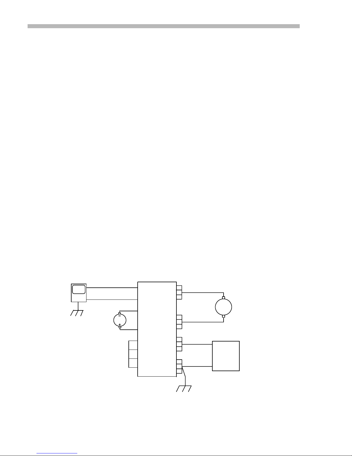
300 SERIES USER GUIDE
Amplifier on Eurocard
Use this checklist for applications that do employ a tachometer. These include
microprocessor control systems that get position feedback from an encoder on the
motor, as well as non-motor applications such as magnet-coil, solenoids, or other loads
that require a set current from the amplifier in response to a control-voltage at the
inputs. The components on the J17 header come from the factory preset for this
operating mode. See functional diagram on page 2.
1. Connect DC power supply to amplifier +HV and GND. Check voltage to see that is is
within the amplifiers' rating.
2. Ground amplifier to chassis at GND pin DD.
3. Connect motor or load between OUT+ and OUT-. Do not ground load!
4. Connect reference voltage source to REF+ and REF- inputs.
5. Ground ENABLE,POS ENABLE, NEG ENABLE to amplifier logic ground.
6. Set REF GAIN pot to full CW.
7. Set FEEDBACK pot to full CW.
8. Set CURRENT LIMIT pot to full CW.
9. Set V
10. Turn power on
11. Check for green LED indicating Normal operation.
12. Adjust BALANCE trimpot for 0.0V between OUT+ and OUT-
13. Momentarily increase Reference voltage (±10V max).
14. Check motor direction: is it OK?
15. Set Reference voltage to maximum value (+/-10V)
16. Check load current at CURRENT MONITOR output
17. Apply step or square-wave signal to Re f-inputs, adjust FEEDBACK CCW for be st
to 0V
ref
YES: continue
NO: remove power, reverse connections to Ref+ and Ref-.
response with no oscillation.
: Current-Mode,
WITH Tachometer
Amplifier Connections
Numbered terminals are on the brown 15-pin connector. Double-letter terminals are on
the orange 4-pin connector. See appendix for connector part numbers.
CONTROLLER
OUT
GND
TACH
ENABLE
POS ENABLE
NEG ENABLE
LOGIC GND
REF+
REF-
AMPLIFIER
+ Eurocard
C2
A2
C6
C4
A14
C12
A12
C16
Fig. 6
C22
A22
C24
A24
C26
A26
C28
A28
C30
A30
C32
A32
C18
A18
C20
A20
OUT+
OUT-
+HV
GND
+
POWER
SUPPLY
-
CHASSIS GND
MOTOR
DC
12
Page 21
300 SERIES USER GUIDE
Power Supply Considerations
1. Determine the maximum voltage required to drive your motor or load at peak current and peak RPM (in
the case of a motor).
Add extra for losses in the amplifier (see p. 10, Output Voltage Swing).
Add an extra 5-10% for power supply ripple.
Use this value, and the amplifier's continuous current rating as your nominal power supply specification
at normal line voltage.
300 series peak currents of 2-2.5X the continuous current rating can usually be tolerated by off-the-shelf
transformer-rectifier-capacitor power supplies.
(See appendix for a complete listing of standard power supplies)
2. Where the amplifier is to be mounted more than 18" away from the power supply filter capacitor, install
a 200uF. (minimum) filter capacitor across the amplifier +HV and Gnd terminals as a local bypass
capacitor. The voltage rating of this capacitor should be compatible with your supply voltage.
3. Use the current monitor output to check for clipping when your system is up and running. This could be
an indication that there is insufficient buss vo ltage to drive the commanded current through the loa d.
4. When operating at lower supply voltages, such as 24V or less, check the Normal LED. If it goes out
occasionally, this could mean that the buss voltage 'sag' during periods of high current demand, and is
lowering the buss voltage below the under voltage cutoff point (<16V). If this occurs, consider using a
larger filter capacitor, or raising the supply voltage.
5. If the load has a high inertia, you may need a regenerative energy dissipator, or larger filter capacitors.
Whe a heavy load is decelerated, the amplifier will transfer energy from the motor to the power supply.
This will 'pump-up' the buss voltage, and can cause either an overvoltage shutdown, or damage the
amplifier.
6. If you see the Normal LED go out when the load is decelerated, it is a sign that the buss is "pumpingup", and you will have to take measures as suggested above, lower the buss voltage, or decelerate the
load more slowly.
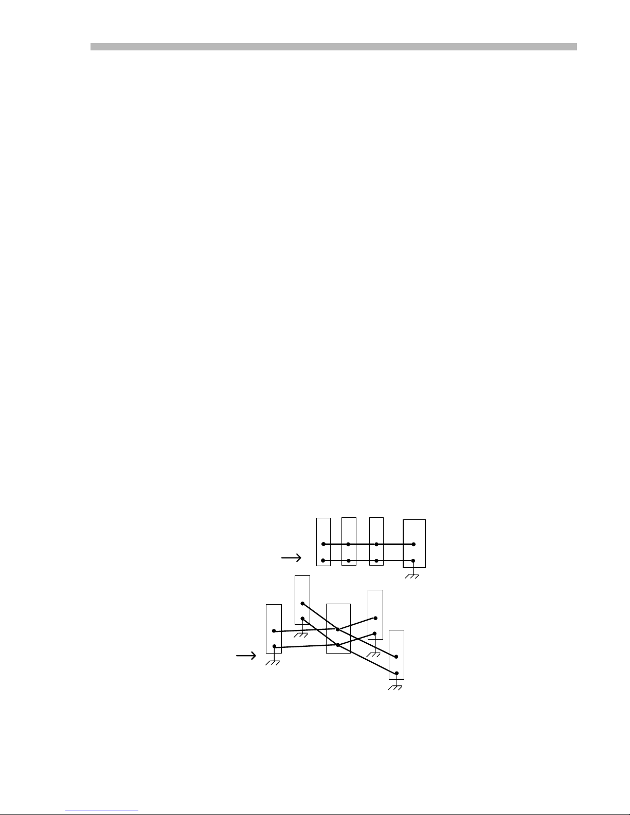
7. When multiple amplifiers are connected to the same power supply, use a 'star' wiring configuration.
Don't 'daisy-chain' amplifiers by connecting one to the next, and so on. Make connections between each
individual amplifier and the power supply, and ground each amplifier at pin DD (P1-4 on the MB4 card)
leaving the (-) terminal of the filter capacitor disconnected from ground. Doing this will keep the
reference and logic inputs of the amplifiers referenced to ground, while the voltage at the negative
terminal of the filter capacito r changes in response to the current dr awn through the amplifier wiring.
8. Regulated power supplies frequently do not have adequate output filter capacity to power a servo
amplifier. T hey can go into over-current foldback during periods of high output currents. If using such
supplies, it may be necessary to add an external filter capacitor (4-5000 uF).
Multiple Amplifier Power Connections
DON'T
DO THIS
AA
DD
DO
THIS
AA
DD
AA
DD
POWER
SUPPLY
+
-
Fig. 7
13
AADDAA
DD
AA
DD
AA
DD
+
POWER
SUPPLY
-
Page 22
300 SERIES USER GUIDE
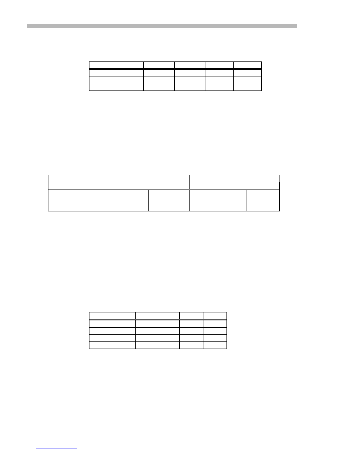
Minimum Inductance
Table 3 lists the minimum inductance required for various amplifier and buss voltage
combinations.
Model 20V 40V 80V 160V
303,303B 63 uH 125 uH 250 uH N/A
306,306A,306AB 30 uH 63 uH 125 uH N/A
312 N/A 175uH 350uH 700 uH
Maximum Inductance
There is no maximum inductance specified for the 300 series, however larger
inductances can reduce the bandwidth and produce excessive ringing in the amplifier's
response. The Standard column in the table below shows the load inductance which are
considered 'normal' for the 300 series amplifiers. The Dash-1 column shows the range of
load inductance which can be driven with amplifiers ordered with the -1 option (see
ordering guide in appendix). Load inductance higher than the maximum values in the
Dash-1 column will result in lower bandwidth, and may require component changes to
optimize compensation.
Model 40V 80V
Standard Dash-1 Standard Dash-1
303, 303B 63 uH to 1.9 mH 2 to 9 mH 125 uH to 3.9 mH 4 to 18 mH
306, 306A, 306AB 32 uH to 0.9 mH 1 to 4.5 mH 64 uH to 1.9 mH 2 to 9 mH
312 88 uH to 5.4 mH 5.5 to 25 mH 175 uH to 10.9 mH 11-50 mH
Table 3
Bandwidth
Table 4
The bandwidth of an amplifier is the frequency at which the amplitude of the output
drops to 70% of the value at a much lower frequency. The effect of bandwidth is to
either limit the frequency of a sine-wave signal that can be amplified, or to limit the
risetime of a step-input signal. The type of load will also have an effect on the
bandwidth, particularly as the inductance increases.
Amplifiers with the -1 option (high inductance loads) will exhibit the specified
bandwidth at higher values of inductance than the standard amplifiers.
Table 5 shows the load inductance and resistance at which the standard and -1 option
amplifiers are rated for their 3 kHz bandwidths. As the load inductance increases beyond
the values listed in table 5, the bandwidth will decrease.
Model BW R L (std) L (-1)
303,303B 3kHz 2.5 250 uH 4 mH
306,306B 3kHz 1.0 125 uH 2 mH
306A,306AB 3kHz 1.0 125 uH 2 mH
312 3kHz 14 700 uH 11 mH
Table 5
BW ; -3dB small-signal bandwidth
R ; Load resistance in ohms
L (std) ; Load inductance in microhenries for standard amplifier
L (-1) ; Load inductance in millihenries for amplifiers with -1 option
14
Page 23

300 SERIES USER GUIDE
Enable Inputs
The polarity of the amplifier's output can be controlled with the Positive and Negative
enable inputs, and the outputs can be completely disabled with the Enable input.
Output polarity control is usually used on motion control systems that use travel -limit
switches. If a moving member hits one of these switches, it is supposed to disable the
amplifier, preventing further travel into a mechanical stop. At the same time, it should be
possible to reverse the direction of the motor to 'back-out' of the limit. Positive and
Negative enable inputs are provided for this function.
For a shutdown of the amplifier (both outputs off), use the Enable input. This signal will
also cause the Normal LED to turn off, and the Normal output to go LO.
The enable inputs use +5V logic signals, external dry-contact, or NPN current-sinking
drivers. Ground is the level required to make the function logically true, and +5V (or
open-circuit) will make the function false (true = enabled, false = disabled).
The Enable signal only may have its' true logic-level inverted by removing the jumper in
header J17 at position-9 (see functional diagram). When this is done, leaving the Enable
input open
Note: The Positive and Negative Enable inputs must always be grounded to enable the
respective outputs.
Current Monitor
, or at +5V will enable the amplifier, and grounding it will shut it down.
Status LED
This is a signal that is a measure of the output current of the amplifier.
The scale factor in amps/volt is listed below. All of the 300 series output a +/-6V signal
when the current is at the peak rated value.
Amplifier Amps/Volt
303,303B 2.0 Table 6
306, 306B 4.17
306A,306AB 5.0
312 1.5
A green Normal LED is on the basic amplifier, the MB4 card, and Eurocard.
It will be ON when operation is Normal:
Buss voltage is within normal limits.
Enable input is true. (See above for details on Enables)
Chassis temperature is <83°C.
No short circuits between outputs, or between outputs and ground.
It will be OFF during a fault condition:
Buss voltage is over or under normal limits.
Enable input is false.
Chassis temperature is >83°C.
A short-circuit has occurred at the outputs.
The short-circuit, and overtemp faults are latching type, that is, they will disable the
amplifier until power is cycled off and on, or until the Reset input is toggled.
Note: The Positive and Negative enable inputs will not af f ect the status of the Normal
LED or Normal output.
15
Page 24

300 SERIES USER GUIDE
Normal Output
This is a +5V CMOS output signal in series with an internal 1.87K resistor.
It will be HI (+5V) when the Normal LED is on, and LO (ground) when the Normal
LED is off. It can drive an external low-current LED, or CMOS logic compatible inputs
to user equipment.
Reset Input
A +5V CMOS logic input which is normally pulled-up to +5V by an internal 100K
resistor. Ground this signal momentarily to reset a fault condition caused by overtemp, or
output short-circuit.
Do not ground this input continuously, as this could cause overloading of the output
stage of the amplifier. If you want to shutdown the amplifier, use the Enable input.
Current Limit
On the basic amplifier, component R8 on header J17 controls the maximum current
delivered by the amplifier. A value of 10K ohms is standard and will let the amplifier
deliver the maximum rated peak current. Substitute smaller values to reduce the limiting
current.
The MB4 and Eurocard come with potentiometers that lets you adjust the maximum
current to any set value from 0, to the maximum rated peak current.
In either case, whenever the current-limit is greater than the continuous current rating of
the amplifier, it will fold-back to the continuous current rating after 1 second for unipolar
currents, or 2 seconds for bipolar currents.
Output Voltage Swing
300 series amplifiers use MOSFET transistors in the output stages. These have no
inherent 'saturation' voltage like bipolar transistors. Instead, they look like low value
resistors in series with the power supply. The table below lists the on-resistance and
output voltage-drop for the various amplifiers.
Note that output voltage swing is relative to the instantaneous supply voltage. Therefore,
if you have an application that requires a particular voltage swing, you must add to this
the output voltage-drop, power supply ripple voltage, and use this as your low-line power
supply operat ing voltage.
Amplifier Rout Vsat
303,303B 0.26 3.12
306,306B 0.13 3.25
306A,306AB 0.13 3.9
312 0.60 5.4
Table 7
Rout is the amplifier output resistance.
Vsat is the voltage-drop (also called saturation voltage) across the amplifier at peak
current.
16
Page 25
300 SERIES USER GUIDE
DC Power Outputs
All internal supply voltages are derived from the high-voltage supply. These internal voltages are
available at the signal connector for certain user applications. All are current-limited by
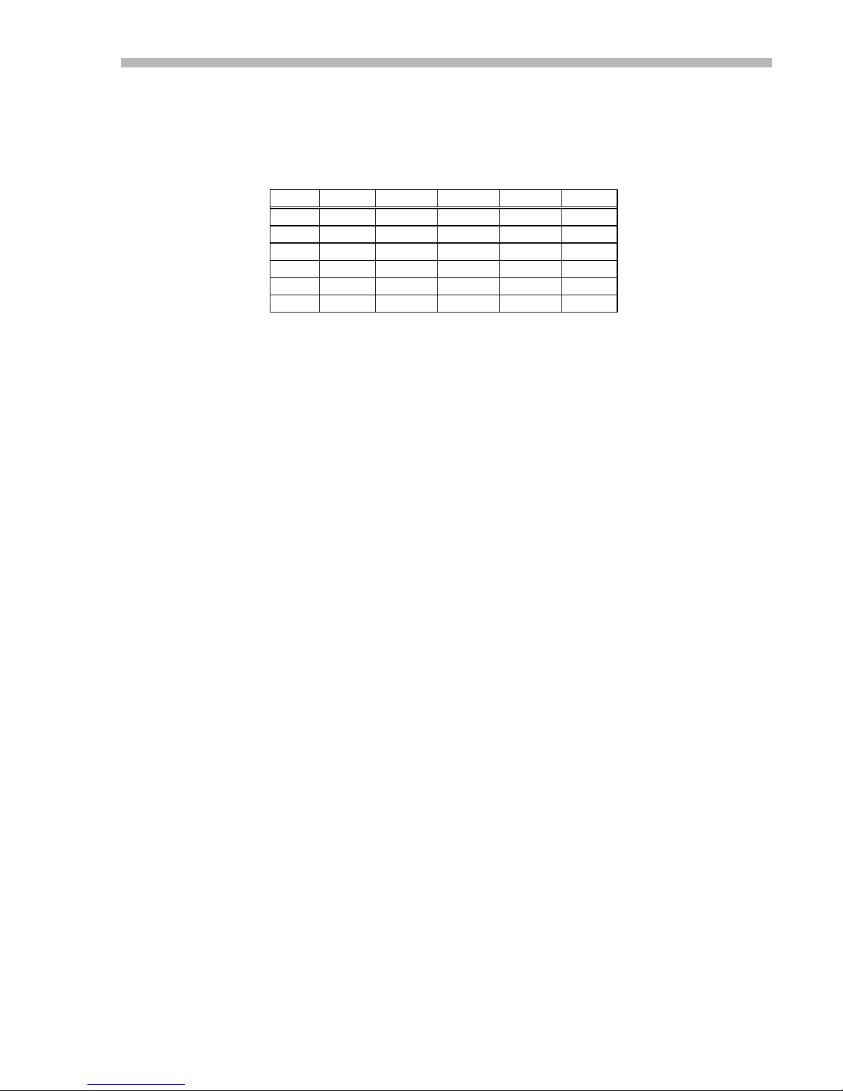
series resistors (Rser) and are intended for low-power applications. Table 8 lists the
connector pin, voltage, and series resistance for each of these outputs:
Vout Std MB4 Eur Rser Iout
22 pin P2 DIN
+5
+11
-11
+14
-14
Std ; Standard amplifier without MB4 card. Pin numbers refer to 22 pin connector.
MB4 ; Amplifier + MB4 card combination. Pin numbers refer to MB4 15 pin connector P2.
Eur ; Amplifier + EC2 Eurocard combination. Pin numbers refer to Eurocard DIN connector
P2.
Rser ; Internal resistance in series with voltage source shown.
Iout ; Permissible current to external loads.
20 n/a n/a 2.49 K 100 uA
6 n/a n/a 20 K 50 uA
8 n/a n/a 20 K 50 uA
18 5 C8 1 K 3 mA
n/a 13 A8 None 1 mA
Table 8
17
Page 26

300 SERIES USER GUIDE
Mounting
Standard Mounting
The standard model comes with plug-in cable connectors. (See appendix for a list of
connector types)
The chassis can be mounted to flat surfaces with four #6 screws that go through four
holes in the amplifier chassis. The mounting surface may provide adequate heat-sinking,
or the amplifier can be ordered with a standard (-H option) or extended -HX option)
heatsink. (See se ction on cooling for hea tsink recommendations)
PC Board Mounting (-P option)
This option changes the connectors from plug-in cable connectors to extended male pins.
These pins permit either soldering directly into p.c. boards, or can plug into springloaded pin sockets like the ones used on the MB4 and Eurocard. Part numbers for these
pin-sockets are listed below:
Connector Pin-Socket
22 pin signal connector AMP: 50864-5
4 pin power connector AMP: 1-50871-0
When mounting on p.c. boards, consider the airflow across the amplifier and ambient
temperature to determine if a heatsink is required.
MB4 Card Mounting ( -M option)
The MB4 mounting card must be used with amplifiers ordered with the -P option. The
card pushes onto the pins in a piggy-back fashion. Thereafter, connections are made to
the MB4 card which connects to the amplifier via the pins.
A Current-limit trimpot is standard on the MB4 card, as are Balance, and Feedback
(internal loop-gain) trimpots.
The MB4 provides additional functions not available on the standard amplifier. These
are:
Voltage-Mode operation with IR compensation (-V option)
PWM Inputs (-P option)
Edge Filters (-F option)
See section on MB4 card for additional information.
Eurocard Mounting (-E and -ER options)
A 3U x 10HP extended Eurocard mount (220 mm) is available with (-ER option), or
without (-E option) a front panel. Trimpots are accessible from the front panel, as are the
current monitor output, status LED, and Rese t push-button switch. Power and signal
connections are all made via a DIN 41612 type “D” connector on the backplane end of
the card.
18
Page 27
300 SERIES USER GUIDE
MB4 Mounting Ca rd
The MB4 card adds features and options to the 300 series amplifiers that are not
available on the basic unit. These include PWM inputs, voltage-mode amplification, IR
compensation, and output 'edge' filters.
The MB4 card connects to the amplifier via connectors J3 & J4. The user makes
connections to the amplifier/card assembly via connectors P1 (motor, and high voltage
DC supply) , and P2 (reference, tach, and aux inputs, and Enable signals).
Notes on Nomenclature
I,O,P ; Inputs TO MB4 Card, and Outputs FROM MB4 Card, P = Passive
P1 ; Motor & DC Power connections to the MB4
P2 ; Signal connections to the MB4
J3 ; Motor & Power connections between the amplifier & MB4 card
J4 ; Signal connections between the amplifier & MB4 card
N.C. ; No Connection
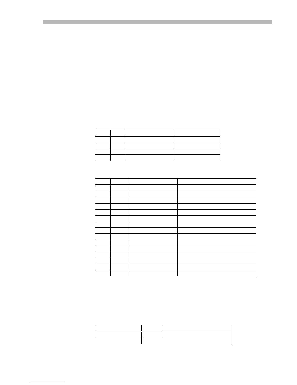
P1: 4 Pin power connector
P1 J3 Signal Name Function
1 AA High Voltage Power input to card
2 BB Neg Output Amplifier output (-)
3 CC Pos Output Amplifier output (+)
4 DD Power Ground Power return
P2: 15 Pin signal connector
Pin Type Signal Remarks
1 I /Neg Enable GND Enables, open-circuit Disables
2 I /P os Enable GND Enables, open-circuit Disables
3 I /Enable GND Enables, open-circuit Disables
4 O Normal HI when Normal, LO if fault
5 O +14V output 14V in series with 1K ohms
6 I T ach Tachometer voltage input
7 I Aux Single-ended co ntrol voltage input
8 I +Ref Input Analog input voltage (+) terminal
9 I PWM Pulse Input (Only with -D option)
10 I /Reset GND momentarily to reset fault
11 P Ground Use for Enable signals
12 I PWM Direction Input (Only with -D option)
13 O -14V Output (with -V option only)
14 P Ground Tacho return input or signal ground
15 I -Ref Input Analog input voltage (-) terminal
Status Output
The Normal o utput signal from the amplifier can be routed direc tly through the MB4
card to this output pin, or can drive an open-drain MOSFET that will be OFF during
normal operation, and turn ON during a fault condition. In this way several amplifiers
can be 'wire-ORed' together to a 'system-OK' line that will be normally HI, and go LO if
any amplifier goes into a fault condition.
Table 11
Table 12
Output type JP-104 Rating
MOSFET output 1-2 50V, 100mA Table 13
Amplifier Normal 2-3 HCMOS in series with 1.87K
Amplifier Signal Connector (J4)
These are the connections between the amplifier and the MB4 card.
19
Page 28

300 SERIES USER GUIDE
They are listed here for information only.
The type of signal (output, input, passive) is relative to the MB4 card, i.e. pin A is the
Ref+ signal that is an output from the card to the amplifier.
Pin Type Description
A O +Ref
B O -Ref
C P Signal Ground
D P Ref Amp Output
E O Aux. Input
F I +11V Output from Amplifier
G P Logic Ground
H I -11V Output from Amplifier
I N.C.
J O /Reset
K I Preamp Output (To Curr-Lim & Feedback Gain trimpots)
L O Wiper from Preamp-Out trimpot (Feedback Gain)
M O Tachometer Input
N P Summing Junction of Servo Preamp in 30X amplifier
O O /Enable
P O /Pos Enable
Q O /Neg Enable
R I +14V Output from Amplifier
S I Normal Signal from Amplifier
T I +5V
U N.C.
V I Current Monitor Output
Output from Amplifier
VREF
MB4 Card Options
The various options available with the MB4 card are described below.
Voltage-Mode (-V option)
Voltage mode changes the amplifier from a vol tage-in, current-out operating mode to
voltage-in, vo ltage-out. (See p. 26 for further information)
IR-Comp (included with -V option)
This can be enabled with jumpers when operating in the voltage mode. IR comp will
increase the amplifier output voltage as the load current increases. When properly
adjusted, it will compensate for the loss of armature voltage that occurs because of the
resistance of the motor-armature, and can provide constant velocity operation without
using a tachometer. (See p. 27 for further information)
PWM Inputs (-D option)
Digital inputs are converted to ±Ref voltages with this option. Useful with
microprocessor controllers, this mode takes a 0-100% PWM and a direction signal as
inputs, or a single PWM signal that outputs a 50% duty cycle as the 0 level, and changes
from 0-100% to emulate full-scale ±Ref voltages. (See p. 29 for further information)
Edge filters (-F option)
An L-R-C filter network that will slow down the rise and fall times (the 'edges') of the
output waveform. This reduces the electrical noise that can couple from motor cables
into surrounding electrical equipment. Another purpose for this option is to supply the
minimum inductance that the amplifier needs to operate printed-circuit, or other low
inductance motors without having to use an external inductor.
Table 14
20
Page 29
300 SERIES USER GUIDE
MB4 Card Jumper Settings
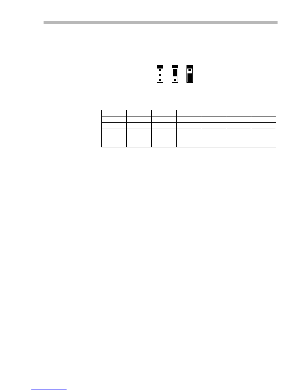
Table 15 shows the settings of the on-card jumpers for the various card and setup
options. Jumpers consist of two-pin shorting connectors on three-pin p.c. board headers.
The shorting connector can connect pins 1-2, or 2-3, as shown below.
Amplifier Mode Input Type
Curr Volt IR Comp Analog PWM PWM
0-100% 50%
JP02
JP182
JP72
JP62
JP63
JP64
Notes on Modes & Jumpers
Positions in the table with no entries
Current mode is the default mode. If the card is ordered with no other options this mode
will be in effect. A voltage at the reference inputs will force a current at the amplifier
outputs.
Voltage mode is delivered with the -V option. The amplifier functions as a voltage
amplifier. A voltage at the reference inputs will force a voltage at the amplifier outputs.
1-2 2-3
2-3 1-2 1-2
2-3 1-2 1-2
1-2 1-2 2-3
1-2 1-2 2-3
2-3 1-2 1-2
PINS
1
2
3
1-2 2-3
Table 15
indicate that the jumper has no effect on this mode.
IR Comp is available only with the voltage option. When using this option the amplifier
output voltage depends both on the reference inputs, and the load current. As the motor
draws more current, the output voltage will increase to compensate for the loss of
armature voltage due to motor's internal resistance. Use this option when you need speed
regulation without a tachometer.
Analog inputs are the default type of input. An analog signal, typically a ±10V signal
controls the amplifier's output. This is true regardless of the selection of current, voltage,
or IR comp modes.
PWM 100% inputs consist of two digital (+5V CMOS logic) inputs instead of the ±10V
signals normally used. The pulse input is a 0-100% duty cycle pulse-width-modulated
(PWM) signal, and the direction signal controls the polarity of the output signal.
Circuitry on the MB4 card converts these digital signals into a +/-5V analog signal that
then is sent to the amplifier.
PWM 50% mode uses only one digital PWM input connected to to pin 12 of P2. For an
output of zero, the PWM signal must be 50% duty cycle. Thereafter, changing the signal
from 0 to 100% duty cycle will force the amplifier to swing its' outputs from maximum
positive, to maximum negative condition.
21
Page 30

300 SERIES USER GUIDE
Eurocard Mount
All connections to the amplifier are made via the DIN connector.
The Eurocard may be ordered with the same additional options as the MB4 card:
Voltage-Mode operation with IR compensation (-V option)
PWM Inputs (-D option)
Edge Filters (-F option)
Heatsink options available with the Eurocard mounting are the -H, and -HX, for standard
and extended heatsink. The 10HP spacing will accept the -H heatsink, but a wider
spacing is required for the -HX extended heatsink.
DIN Connector Pinouts
C A
+Ref Input !!!! 2 !!!! -Ref Input
Signal Ground !!!! 4 !!!! Signal Ground
Tach Input !!!! 6 !!!! Aux Input
+14V !!!! 8 !!!! -14V
Logic Ground !!!! 10 !!!! Current Monitor
/Pos Enable !!!! 12 !!!! /Neg Enable
/Reset !!!! 14 !!!! /Enable Viewed from
Logic Ground !!!! 16 !!!! Status backplane
Power Ground !!!! 18 !!!! Power Ground wiring-side.
Power Ground !!!! 20 !!!! Power Ground
Pos Output !!!! 22 !!!! Pos Output
Pos Output !!!! 24 !!!! Pos Output
Neg Output !!!! 26 !!!! Neg Output
Neg Output !!!! 28 !!!! Neg Output
High Voltage !!!! 30 !!!! High Voltage
High Voltage !!!! 32 !!!! High Voltage
Note that the power ground, pos/neg outputs, and high voltage signals each share four
pins. These pins should be wired together on the backplane so that the higher currents
carried by these these signals are shared by the pins.
Jumper Settings
1. Basic: Standard voltage to current configuration
2. Voltage Mode: Voltage-in to voltage-out mode.
3. IR Comp Voltage mode with armature resistance compensation
4. PWM 0-100%: PWM signal applied to REF+ input, Direction signal applied to REF- input.
5. PWM 50%: PWM signal applied to REF- input, 50% duty cycle gives 0 output, 0 and 100%
duty cycle give max positive/negative outputs.
JUMPER BASIC VOLTAGE IR PWM PWM Signal
only COMP 0-100% 50%
JP-101
JP-102
JP-104
JP-105
JP-106
JP-107
JP-108
JP-109
Table 16
1-2 1-2 2-3 Amp Aux
1-2 1-2 2-3 Curr Mon
1-2 2-3 PWM type
2-3 2-3 2-3 1-2 1-2 Amp Ref+
2-3 2-3 2-3 1-2 1-2 Amp Ref2-3 1-2 1-2 Amp Tach
1-2 1-2 1-2 2-3 2-3 Card Ref+
1-2 1-2 1-2 2-3 2-3 Card Ref-
Table 17
22
Page 31

300 SERIES USER GUIDE
Status Output Jumper
JP-103: 1-2 for open-drain MOSFET output, 2-3 for HCTTL output. Normal = HI (HCTTL),
or off (MOSFET), fault = LO (HCTTL), or ON (MOSFET).
Tuning and Adjustments
First we describe the operation of the trimpots on the basic amplifier, and the MB4 and
Eurocard. Next are more detailed sections on particular subjects such as tachometer
scaling, voltage-gain, and so on. For more detailed theory and practice, a list of
references is included in the appendix.
Trimpots
Balance and Feedback trimpots come on both basic amplifier and MB4 card. Currentlimit comes only with the MB4 card and Eurocard. Voltage-feedback and IR-Comp are
only installed on MB4 and Eurocards with the -V option (armature-voltage feedback).
Balance
Used to 'null' the output of the amplifier when the reference inputs are at 0V. Adjust the
pot for zero-current (or zero-volts measured between Out+ and Out-) when the input to
the amplifier is zero.
Feedback
Sets the gain of the servo preamplifier. Usually set to minimum (fully CW) in currentmode operation for maximum bandwidth. When using tachometers, turn this pot CCW
until oscillation begins, and then back off 1-2 turns for stable operation. Adjustment of
this pot affects the response of the amplifier to a step-input.
Current Limit
Controls the peak current that the amplifier can output to the load. Fully CW the
amplifier will drive the rated peak current. As this is turned CCW, the maximum current
will gradually decrease. Useful for protecting mechanical parts when the maximum
current required by the load is less than that of the amplifiers peak rating.
Voltage Feedback
Sets the voltage-gain of amplifiers ordered with the MB4 or Eurocard with voltagefeedback (-V) option. The gain of the amplifier is x22 with this pot fully CCW, and can
be adjusted upward by rotating this pot CW. See the following section (p.27) on voltagegain adjustment for more information on this trimpot.
IR Comp
Used in voltage-feedback mode with jumpers set for IR-comp. Adjusts the amount of
positive-feedback from the current-sense circuit. This feedback increases the output
voltage when drawing higher currents in the load. Because this is positive feedback, too
much of it can cause severe oscillation. When adjusted correctly the motor speed will
remain constant within several percent as the load changes without using a tachometer.
23
Page 32
300 SERIES USER GUIDE
Mode Setting: Flat-Gain vs. Tachometer
In current mode operation, the amplifier functions as a single-input, single-output
transducer that converts an input voltage to an output current. Use of a tachometer is
optional.
When no tachometer is used, the amplifier is operated in the flat gain mode. This
configuration gi ves the maximum bandwidth. When driving motors, it is usually
preferred over voltage-mode operation because it makes the motor respond faster. A
large signal,
is set to a low value. The overall gain of the amplifier is typically Ipeak / 10V, and
remains relatively constant over the amplifiers bandwidth.
Using a tachometer means that the servo preamplifier now must amplify the difference
between the reference input signal, and the signal from the tachometer. Since this is a
much smaller signal, the servo preamplifier is operated at a much higher gain. This gain
must also change with frequency, to compensate for the characteristics of the
motor-tachometer combination.
The components on the J17 header socket determine the overall response of the
amplifier. The standard setup is for flat gain. Some components must be changed for
tachometer operation. If the gain is too high in tachometer mode, alternate component
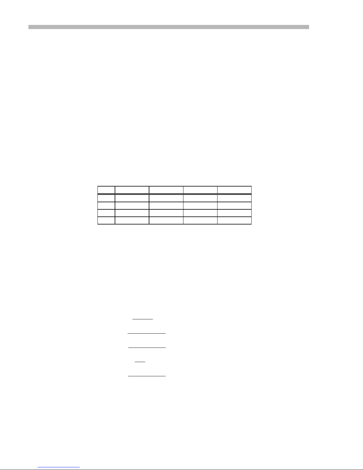
values are suggested which will reduce the gain by a fact or of 3, and 5. The table below
lists the components on J17 for the various setups:
, is sent to the servo preamplifier, so the gain of the servo preamplifier
Vref
Flat Tach Tach/3 Tach/5
330 pF 330 pF 1 nF 1.5 nF
C4
46.4 K 499 K 150 K 100 K
R5
10 nF 10 nF 33 nF 47 nF
C6
0 10 M 3 M 2 M
R7
Table 18
The diagram on the following page illustrates the frequency response of the servo
preamplifier in the different gain configurations. Here are some equations for the
important points on the performance curve. These all apply to the servo preamplifier
stage as driven b y the i nput differential amplifier through a 50K ohm resistor (R11) ,
with tachometer feedb ack coming through a 50K ohm resistor (R1+R2), and with the
Feedback trimpot set to the fully CW position. Turning this pot fully CCW will add an
additional 21dB gain while maintaining the same frequency response. (See functional
diagram)
Parameter Equation Flat Tach Tach/3 Tach/5 Unit
+57
DC Gain
Low-frequency Break
Low-frequency Zero
Mid-frequency Gain
High-frequency Break
RR
=
A
DC
=
1
f
×× ×
276
=
2
f
×× ×
256
=
A
MID
R
=
3
f
×× ×
254
0.93 210 63 42 n/a
11
R
1
RC
π
1
RC
π
R
5
0.93 10 3 2 n/a
11
1
RC
π
n/a 1.59 1.61 1.69 Hz
n/a 32 32 34 Hz
10.4 0.97 1.06 1.06 KHz
24
Page 33

300 SERIES USER GUIDE
Frequency Response with Tachometer
The curves below show the gain and phase for the servo preamplifier when using the J17
components setup for normal tachometer mode, and for the 1/3 and 1/5 gain modes as
shown in the table on the preceding page.
25
Page 34
300 SERIES USER GUIDE
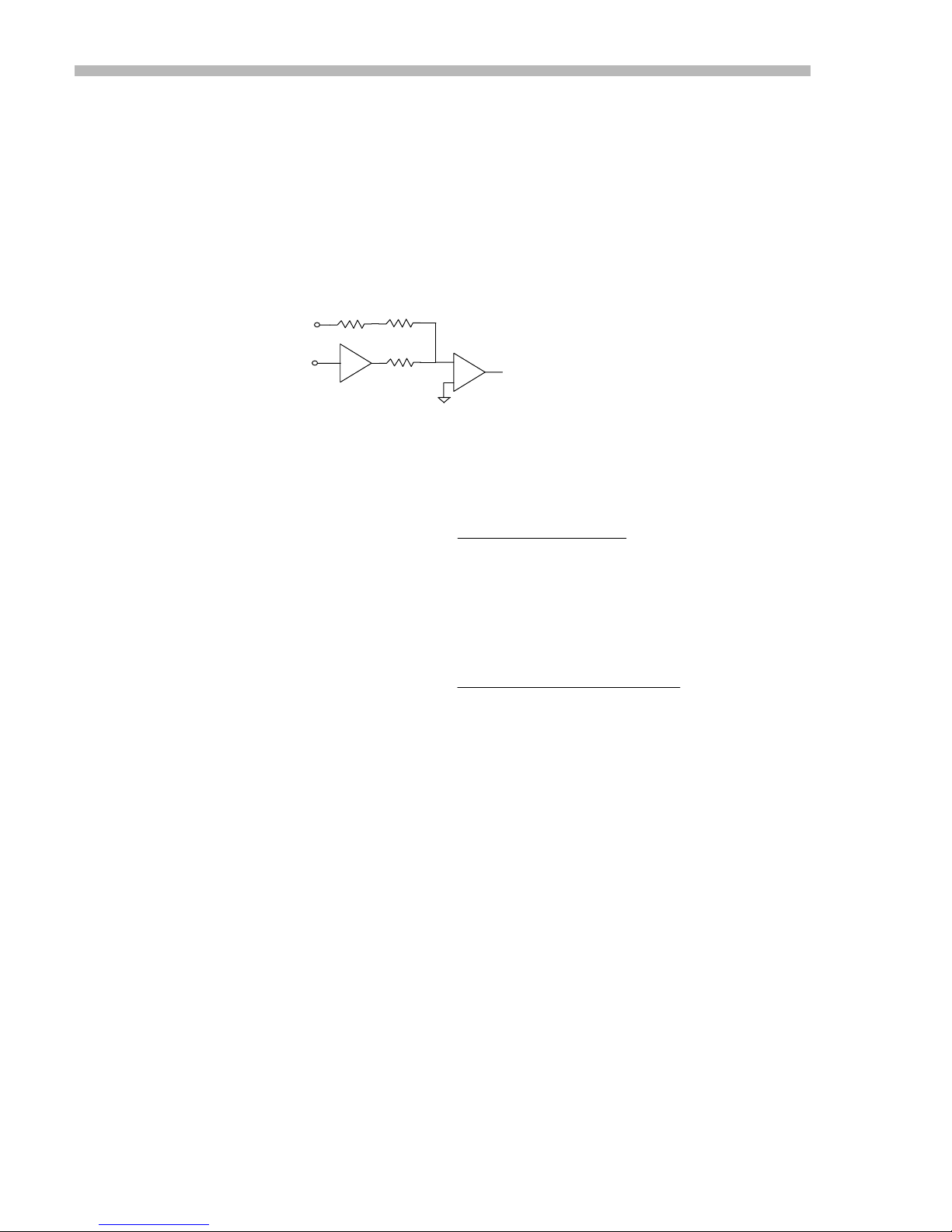
Tachometer Scaling
As delivered, a +/-10V reference signal will drive the motor to a speed at which the
tachometer produces a -/+8V signal, regardless of RPM. Tachometer scaling refers to the
selection of components on the J17 header so that a particular signal at the reference
inputs will drive a motor to a particular RPM. Before you begin, you must know the
RPM of the motor when your control system is delivering its' maximum signal to the
amplifier. In addition, you must know the voltage coefficient of the tachometer (usually
in volts per thousand RPM or V/KRPM) and the amplitude of the signal the control
system puts out at maximum. The figure below shows the relation of the components that
are used in tachometer scaling:
TACH
REF
INPUTS
We can treat R1 and R2 as a single resistor, and compute the value of this resistor while
keeping R11 at the stock value of 50K. Let V
maximum RPM, and let Vin be the reference voltage at maximum RPM. The value of
R1+R2 will now be seen as:
Suppose that you have a motor that is to run at 4000 RPM ( 4 KRPM) with a reference
signal of +/-8V, and a tachometer with Ktach = 7 V/KRPM. We can now compute
(R1+R2) as:
This will give us 218.8K as the value of R1+R2. This is close to 220K, a stock value.
Now R2 = 40K, so this leaves R1 = 180K, also a stock value. Change the component R1
on header J17 to a 180K resistor to complete the procedure.
R1
X0.8
GAIN
R2
SERVO
R11
Fig. 8
()
RR
12
+=
()
RR
12
+=
PREAMP
-
+
K Ktach KRPM
50
Fig. 9
K V KRPM KRPM
50 7 4
R1, R2, and R11 are found on the
J17 component header.
Stock values are:
TO
.
08
R1 = 10K
R2 = 40K
R11 = 50K
be the tachometer voltage at
tach
×
Vref
/
.
V
08 8
×
PWM
STAGE
××
××
Fig. 10
Note that tachometer scaling is a DC gain setting process. Additional compensation may
be required (i.e. lead networks in the tachometer input circuit) to optimize AC operation
with a tachometer. Component C3 on the J17 header can be used in conjunction with R1
and R2 to create such networks. Calculation of these values is beyond the scope of this
manual (see Reference section in appendix).
26
Page 35
300 SERIES USER GUIDE
Voltage-Mode Gain
This setup applies to MB4 and Eurocards that have been ordered with the -V option, for
voltage feedback.
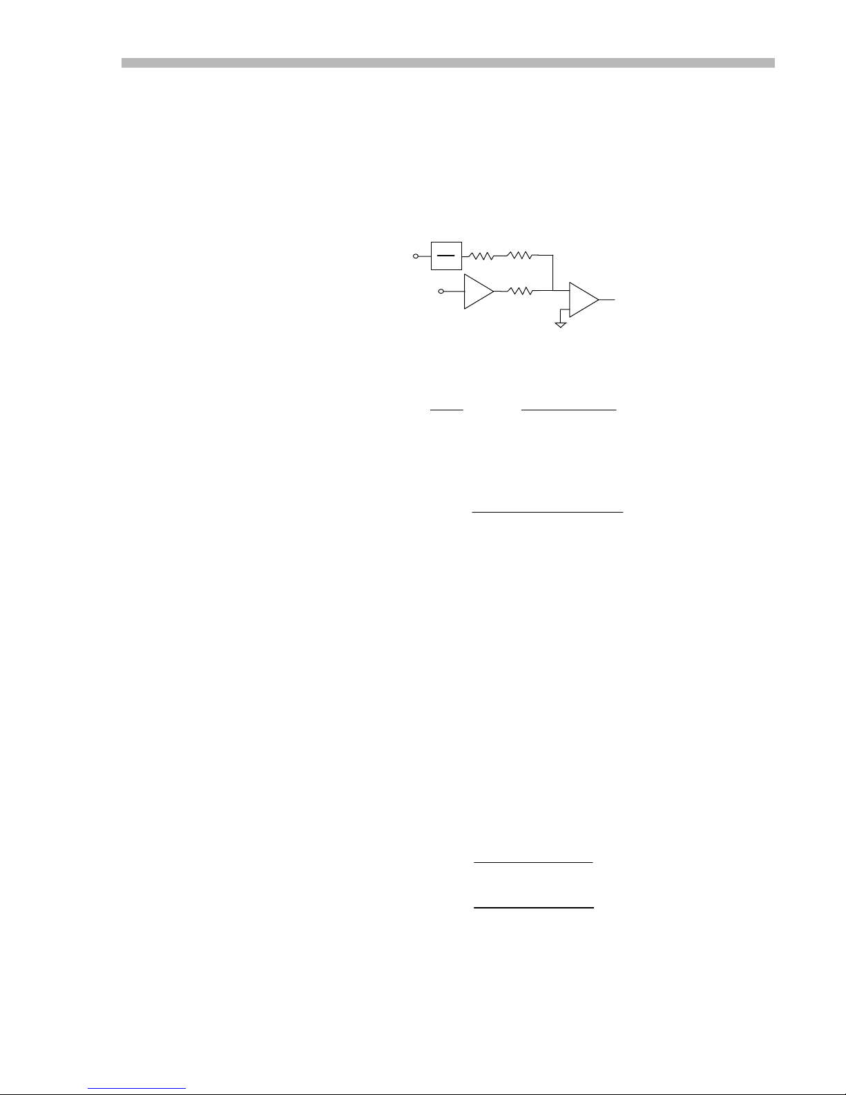
A voltage-sensing circuit attenuates the amplifier's output voltage by a factor of 22. This
voltage is then fed-back into the Tach input. Setting the voltage-gain then is similar to
setting-up a system with a tachometer.
Notice the similarities between the circuit below, and the one shown above for a
tachometer-feedback system:
We can now express the voltage gain like this:
Vout
REF
INPUTS
1
22
Vout
Vref
R1
X0.8
GAIN
R2
R11
Fig. 11
×=
8.0
Fig. 12
SERVO
PREAMP
-
+
()
+×
11
R
RR
PWM
STAGE
2122
TO
And rearrange to solve for R11 like this:
×+×.( )
17 6 1 2
=
R
11
This equation holds true when R31, the voltage-gain trimpot is set fully CCW (counterclockwise). As this pot is turned CW (clockwise) the gain will increase to a value limited
only by the gain of the servo preamplifier stage. The best procedure is to set the gain by
the equation above to a value slightly less than the ideal, using stock resistor values.
Then adjust R31 for the exact gain desired, which must always be slightly greater than
the gain set by the equation.
Changing R2 from 40K to 0 ohms (jumper), and R11 from 50K to 180K will result in a
voltage gain of 0.98, as R1 = 10K, which is the minimum value that you should use for
the (R1+R2) equivalent. Adjusting R31 will now set the gain to 1.00 which means that a
reference voltage of 10V will drive the outputs to 10V.
Suppose that you are operating at a nominal 75V buss, and want to control a 60V swing
at the outputs with a 10V reference signal. The voltage gain would be 60/10 or 6.0.
Use these values in the equation above and see that the new value of R11 would be
29.3K ohms. By using a 33K ohm value, the trimpot R31 on the MB4 can then be used
to adjust the gain upwards slightly to an exact 6.0.
17 6 10
=
R
11
17 6 10 10
=
R
11
R Kohms
11 29 3
=
RR V
out
V
Fig. 13
.
.
KV
××
V
out
××
KV
V
60
.
ref
ref
Fig. 14
27
Page 36

300 SERIES USER GUIDE
IR-Comp
Setup Procedure
Two methods are presented here. Use the one that seems to be the most appropriate to
your installation, and equipment available.
First, remember that IR-comp is used in the voltage mode. So determine that the voltage
gain of the amplifier has been set correctly (see proceeding section).
Next set the trimpots as follows:
Feedback pot (R42) = Max CW ; Minimum loop gain
Voltage Feed back pot (R31) = Max CCW ; Lowest voltage gain
IR Comp pot (R51) = Max CCW ; Zero IR comp
Current Limit pot (R41) = Max CW ; Maximum current
Balance pot (R61) = Centered ; Minimum offset
Finally, be sure that the p.c. board jumpers are set correctly:
Jumper Pins
JP 62 2-3
JP 63 2-3
JP 64 1-2
Table 19
Static Setup Method
Equipment required: Voltmeter, DC source (A 1.5V battery and a switch will do)
1. Adjust the Feedback pot CCW until oscillation appears (squealing sound). Turn po t 2 turns
CW. Oscillation should cease.
2. Find motor armature resistance from datasheet. Add to this the motor brush resistance to find
total resistance seen by amplifier.
3. Adjust Reference voltage for a test current that is about 20% of full value. Check current
monitor to confirm this current. I.e., the current monitor shows 6.0V at amplifier peak current.
Adjust
for a monitor output of 1 volt.
Vref
4. Compute the test current as follows:
×
VI
mon peak
=
I
arm
6
V
Fig. 15
I
= Motor armature current
arm
V
monitor
I
peak
= Current monitor voltage
= Amplifier peak current rating
5. Lock the motor shaft to prevent rota tion, and with the test curre nt flowing through the load,
adjust the IR Comp pot (R51) such that the output voltage increases by an amount Vdiff:
V diff = I
I
R
= Armature current
arm
= Armature resistance
arm
arm
X R
( Output voltage increase )
arm
6. Monitor the motor for overheating while performing this procedure. Apply the test voltage in an
on-adjust-off fashion. Note that the motor must be stationary while making this adjustment.
28
Page 37

300 SERIES USER GUIDE
Dynamic Setup Method
Equipment required: Oscilloscope, signal generator (square wave, 1 Hz.)
1. Adjust the Feedback pot CCW until oscillation appears (sq uealing sound). Turn pot 2 turns
CW. Oscillation should cease.
2. Apply square wave to Reference voltage inputs. Monitor current monitor test point (TP2) with
oscilloscope.
3. Adjust IR comp pot (R51) CCW while monitoring waveform on the oscilloscope.
4. Response time of current to square wave should gradually decrease. Stop turning R51 when
waveform begins to show overshoot.
Notes on IR Compensation
IR compensation works as a form of positive feedback that increases the amplifier output
voltage to compensate for the voltage lost across the motors' internal resistance. If this
compensation is increased too much, the system will oscillate. Correct compensation will
be found as the point where the motor load can be increased, and the motor speed will be
maintained at a relatively constant value. If motor speed increases when a load is
applied, there is too much IR comp, and R51 should be turned CW until speed remains
constant under load. On the other hand, if motor speed decreases too much under load,
turn R51 more CCW until speed is held constant.
If you are in a situation where you cannot apply either of the two methods described
above, you can still adjust IR comp relatively well by simply setting the pots as described
above, and then turning R51 (IR comp) gradually CCW while operating the motor under
changing load conditions. By noting that IR comp is too much, or too little you can find a
setting that compensates best without oscillation and overshoot, or slowing down under
load.
If you have to change the speed of the motor in response to the reference voltage (i.e.,
the voltage-gain) this is done by setting R31 (Voltage feedback pot) with R51 at the fully
CW setting. Once the speed is set correctly, begin adjusting R51 (IR comp) to its best
setting. These two pots will interact, so it is important to set the speed first, and then
adjust the IR comp pot next
When adjustment is complete, continue to cycle the motor under varying load conditions
to confirm the pot settings under all of the anticipated load conditions.
29
Page 38
300 SERIES USER GUIDE
PWM Operation
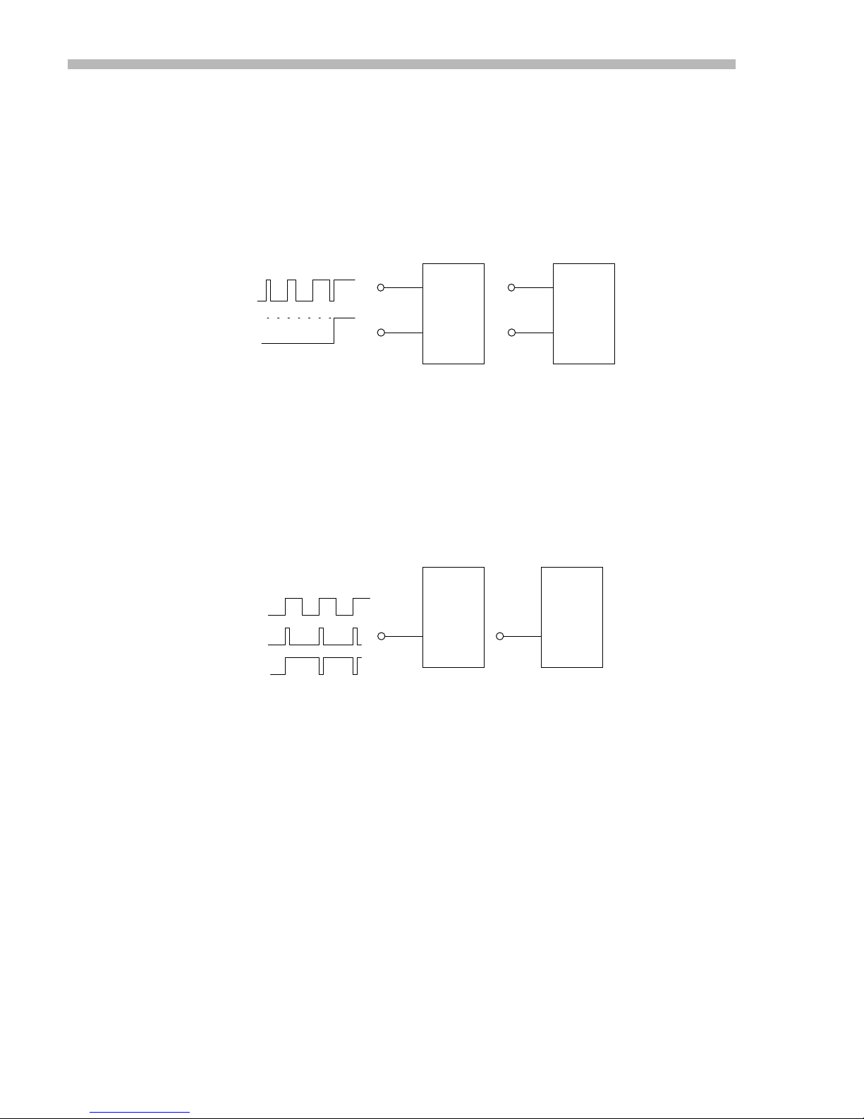
PWM signals are of two distinct types that we refer to as 0-100% and 50%.
The 0-100% type uses two signals: one to control the amplitude and the other to control
direction. The 50% type uses only one signal that is at 50% duty cycle for a zero output
from the amplifier, and changes to 0, or 100% for full output in the positive, or negative
directions.
The table of jumper setting shows how to setup the MB4 card for the different modes.
Connections for the 0-100% type of inputs are shown below:
PWM PULSE
0-100%
NEG
POS
PWM DIR
P2-9
P2-12
MB4
+
AMP
JP-104 = 1-2
2C
2A
Eurocard
+
AMP
JP-104 = 1-2
Fig. 16
The PWM signals should be +5V CMOS compatible, and the 0-100% signal should be
normally LO, going HI for 0-100% duty cycle to enable the amplifier.
The DIR signal will cause an immediate change in the polarity of the voltage going to the
amplifier. Control systems will usually change the polarity of this signal when the 0-
100% signal is at 0% to eliminate jerkiness in the motor.
Here are the connections for a 50% type of PWM system:
FOR
OUTPUT
of
ZERO
10%
90%
PWM SIGNAL
P2-12
MB4
+
AMP
JP-104 = 2-3
2A
Eurocard
+
AMP
JP-104 = 2-3
Fig. 17
Note that a 50% duty cycle signal now produces zero current at the output of the
amplifier. Changing from 50-0% duty cycle will increase the current in the positive
direction, and going from 50-100% increases the current from 0-100% in the negative
direction.
PWM inputs can be used in either the current or voltage modes of operation.
In current-mode, the feedback trimpot may have to be adjusted to increase the gain of
the amplifier because of the lower (±2.5V) signals that now control the amplifier.
In voltage mode, adjust the voltage gain based on a reference voltage of 2.5V (see
previous section on voltage-mode and gain-setting).
30
Page 39

300 SERIES USER GUIDE
Appendix
Connector Part Numbers
Here are the Copley Controls Corp.(CCC), and OEM part numbers for the connectors
used with the 300 series amplifiers:
Basic Amplifier 4-pin power/motor connector
CCC No. 57-0073 (Weidmuller BL4.12593.6)
Basic Amplifier 22-pin signal connector (housing only)
CCC No. 57-0074 (Molex 22-01-3227)
MB4 Card: 4 pin power/motor connector
CCC No. 57-0073 (Weidmuller BL4.12593.6)
MB4 Card: 15 pin signal connector (housing only)
CCC No. 47-0006 (Molex 22-01-2157)
Pins for 15, 22 pin signal connector
CCC No. 46-0000 (Molex 08-50-0114, crimp-tool 11-01-0037)
DIN backplane connector for Eurocard mount
CCC No. 57- (Schroff 69001-698)
References
1. Electrocraft Corp., DC Motors, Speed Controls, Servo Systems, ( Electrocraft Corp.,
1980)
2. Benjamin C. Kuo, Automatic Control Systems, (Englewood Cliffs, NJ: PrenticeHall, Inc., 1982)
3. Jacob Tal, Motion Control Applications, (Palo Alto, CA: Galil Motion Control,
1989)
4. Richard C. Dorf, Modern Control Systems, (Reading, MA: Addison-We sley
Publishing Company, 1980)
5. Richard W. Miller, Servomechanisms: Devices & Fundamentals, (Preston, 1977)
Standard Power Supplies
31
Page 40

300 SERIES USER GUIDE
MB4 Card Layout
32
Page 41
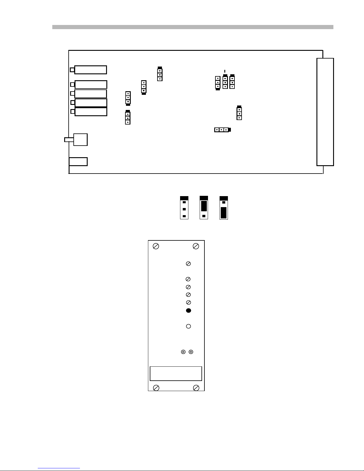
300 SERIES USER GUIDE
Eurocard Layout
R21
R11
R18
R19
R12
S1
P1
JP102
JP107
Jumper Pin Numbering
Panel Layout
JP101
JP103
1
2
3
PINS
JP104
JP105
1-2 2-3
JP106
JP109
JP108
P2
BALANCE
REF GAIN
CURR LIMIT
FEEDBACK
ARM FB.
NORMAL
RESET
CURR MON.
33
Page 42

300 SERIES USER GUIDE
MB4 Card Schematic
34
Page 43

300 SERIES USER GUIDE
Eurocard Schematic
35
Page 44

300 SERIES USER GUIDE
Ordering Guide for 300 Series
36
Page 45

The 300 Series Amplifier User' s Guide
Rev 07 5/98
Page 46

The 300 Series Amplifier User’s Guide
Rev 07 5/98
All Rights Reserved
Corporate Office, USA
410 University Ave.
Westwood , MA 02 090
Tel: 617-329-8200
Fax: 617-329-4055
Visit us on the web @ http://www.copleycontrols.com
West Coast, USA
San Jose, CA
Tel: 408-997-9209
Fax: 408-997-9218
e-mail: [email protected]
Far East, Japan
Tel (044) 833-8694
Fax (044) 833-9594
Page 47
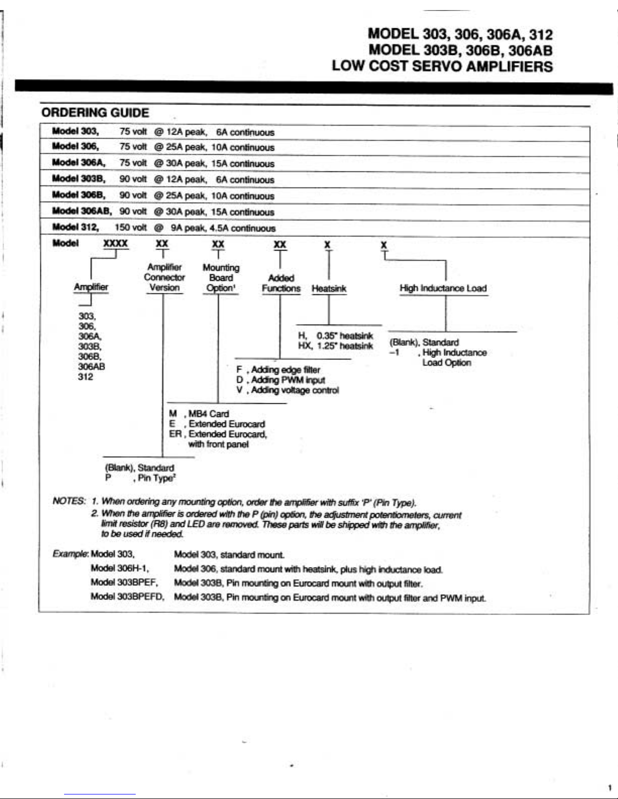
 Loading...