

Page 1
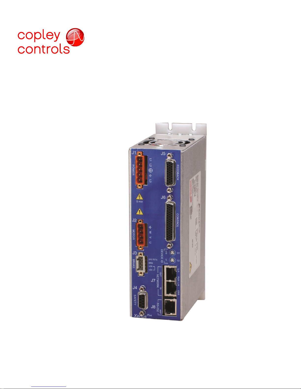
Xenus Plus Compact
STO Manual
P/N 16-01553 Rev 00
September 12, 2016
Page 2

Xenus Plus Compact STO Manual 16-01553 Rev 00
Table of Contents
1.0 About This Manual .................................................................................................................................................... 4
1.1 Title, Number, Revision ........................................................................................................................................... 4
1.2 Revision History ...................................................................................................................................................... 4
1.3 EC Declaration of Conformity .................................................................................................................................. 4
1.4 Original Instructions................................................................................................................................................. 4
1.5 Purpose and Scope of This Document ................................................................................................................... 5
1.6 Product Naming....................................................................................................................................................... 5
1.7 Disclaimer ................................................................................................................................................................ 5
1.8 Related Documentation ........................................................................................................................................... 6
1.9 Reference Standards .............................................................................................. Error! Bookmark not defined.
2.0 Risk Assessment & Responsibility of the Installer ............................................................................................... 8
3.0 Warnings .................................................................................................................................................................... 8
3.1 Operate drives within the specifications provided in the relevant hardware manual or data sheet. ....................... 8
3.2 Risk of electric shock .............................................................................................................................................. 8
3.3 Disclaimer ................................................................................................................................................................ 8
3.4 Installation Overview ............................................................................................................................................... 9
3.5 Definitions ................................................................................................................................................................ 9
4.0 Introduction to the Xenus Plus COMPACT ........................................................................................................... 10
4.1 Product Description ............................................................................................................................................... 10
4.2 Model Overview & Numbering .............................................................................................................................. 10
5.0 Specifications Overview ......................................................................................................................................... 11
5.1 Control Modes ....................................................................................................................................................... 11
5.2 Command Sources................................................................................................................................................ 11
5.3 Power Sources ...................................................................................................................................................... 11
6.0 STO Architecture and Function ............................................................................................................................. 12
6.1 STO Channel Operation ........................................................................................................................................ 13
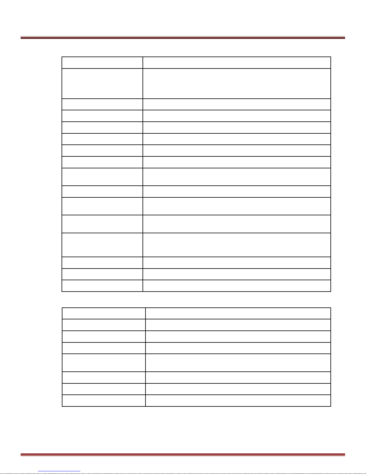
6.2 STO Function Specifications ................................................................................................................................. 14
6.3 Environmental Specifications ................................................................................................................................ 14
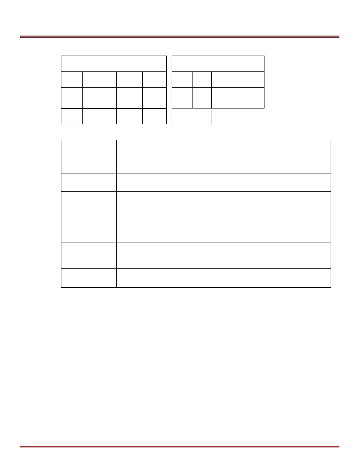
6.4 Safety Related Parameters ................................................................................................................................... 15
6.5 Regulatory Specifications ...................................................................................................................................... 15
6.6 Limitations and Necessary Risk Reductions ......................................................................................................... 16
6.6.1 Electrical Isolation ......................................................................................................................................... 16
6.6.2 DC Brush Motors ........................................................................................................................................... 16
6.6.3 180 Degree Electrical Movement .................................................................................................................. 16
6.6.4 Loads and Other Torque/Force Producing Sources ..................................................................................... 16
6.6.5 STO Input Signal Level ................................................................................................................................. 16
6.6.6 Control Modes and STO ............................................................................................................................... 16
6.6.7 24V DC Power Supply................................................................................................................................... 17
Copley Controls Page 2 of 31
Page 3

Xenus Plus Compact STO Manual 16-01553 Rev 00
6.6.8 AC Mains Over-Voltage Category ................................................................................................................. 17
6.6.9 Wiring to the STO Inputs ............................................................................................................................... 17
6.6.10 Periodic Test Requirements ......................................................................................................................... 17
7.0 Installation Using STO for Xenus Plus Compact ................................................................................................. 18
7.1 STO Wiring Overview ............................................................................................................................................ 18
7.1.1 STO Power Requirements ............................................................................................................................ 18
7.1.2 STO Wiring Requirements ............................................................................................................................ 18
7.1.3 STO (Safety) Cable Connector ..................................................................................................................... 19
7.1.4 Wiring Example:SIL 3/Cat. 3 PL d Emergency Stop - Stopping Category 1 ................................................. 20
7.1.5 XENUS PLUS COMPACT Configuration ...................................................................................................... 20
7.1.6 Example STO Timing .................................................................................................................................... 21
7.2 Start-Up Checklist ................................................................................................................................................. 22
7.2.1 Preliminary checks ........................................................................................................................................ 22
7.2.2 Start-Up Checklist ......................................................................................................................................... 23
7.3 STO Status Indications ......................................................................................................................................... 24
7.3.1 J8 AMP LED .................................................................................................................................................. 24
7.3.2 STO Circuit Status Data Objects ................................................................................................................... 24
7.3.3 CME2 Control Panel...................................................................................................................................... 25
7.4 Troubleshooting..................................................................................................................................................... 26
7.4.1 How to tell if the STO function is active......................................................................................................... 26
7.4.2 How to tell if the STO function is inactive ...................................................................................................... 26
7.4.3 Why can’t the STO function be deactivated? ................................................................................................ 26
7.4.4 Why can’t the STO function be activated? .................................................................................................... 26
7.4.5 The drive is hardware-enabled but the motors don’t move. .......................................................................... 26
8.0 Maintenance ............................................................................................................................................................. 27
8.1 Accessibility and Replacement of Internal Parts ................................................................................................... 27
8.2 Periodic STO Testing Interval ............................................................................................................................... 27
8.3 Periodic Testing Checklist ..................................................................................................................................... 28
9.0 Muting & Suspension of Safety Functions ........................................................................................................... 29
9.1 STO Muting ........................................................................................................................................................... 29
10.0 Decommissioning ................................................................................................................................................... 30
Page 3 of 31 Copley Controls
Page 4
Xenus Plus Compact STO Manual 16-01553 Rev 00
Title
Xenus Plus Compact STO Manual
Document Number
16-01553
Current Revision
00
Revision
Date
ECO #
Comments
00
9/12/2016
ECO-063895
Originated
Table 1
Table 2
1.0 About This Manual
1.1 Title, Number, Revision
1.2 Revision History
1.3 EC Declaration of Conformity
The products covered by this manual comply with the EC Directives 2014/30/EU (EMC Directive), 2014/35/EU (Low
Voltage Directive), 2006/42/EC (Machinery Directive) and 2011/65/EU (RoHS Directive). The complete EC Declaration of
Conformity is available on the internet at www.copleycontrols.com.
Name and Address of the Manufacturer: Name and Address of the authorized representative:
Analogic Corporation d/b/a Copley Controls BK Medical ApS
20 Dan Road Mileparken 34, DK-2730
Canton, MA 02021 Herlev
USA Denmark
1.4 Original Instructions
This manual is considered to be “original instructions” as defined in EC Directive 2006/42/EC and the contents have been
verified by Copley Controls.
Copley Controls Page 4 of 31
Page 5

Xenus Plus Compact STO Manual 16-01553 Rev 00
1.5 Purpose and Scope of This Document
This document is intended to inform the reader about the Functional Safety features of the Xenus Plus Compact
servo drive models and to provide information on the steps required to install it into systems so that a target
level of Functional Safety performance can be achieved. The scope of this document is limited to those aspects
of Functional Safety that relate to the installation, operation, and maintenance of the
Xenus Plus Compact.
1.6 Product Naming
The STO function is the same in XEC, XPC, 801-1891, 801-1892, and 801-1893 models.
References to Xenus Plus Compact in this document should be understood as references to all of these
models.
1.7 Disclaimer
This manual contains information on the Safe Torque Off (STO) feature of the Xenus Plus Compact servo drive
and how it may be incorporated into an industrial motion control system. While every effort has been made to
ensure the completeness and accuracy of this manual it must be emphasized that the responsibility for
functional safety in the overall system into which the drive is installed rests ultimately with the manufacturer of
the system into which the Xenus Plus Compact is installed.
The equipment manufacturer which must take into account all the aspects of the system of which the
Xenus Plus Compact is a component.
Copley Controls does not accept any liability for direct or indirect injury or damage caused by the use of
information in this document. The equipment manufacturer is always responsible for the safety of its product and
its suitability under applicable laws. Copley Controls hereby disclaims all liabilities that may result from this
document.
Page 5 of 31 Copley Controls
Page 6

Xenus Plus Compact STO Manual 16-01553 Rev 00
1.8 Related Documentation
These documents have additional information on the Xenus Plus Compact and are required for proper installation
and commissioning of the drives.
Available upon request from Copley Controls:
User Guide
Xenus Plus Compact User Guide (Document No. 16-01552)
Datasheet
Xenus Plus XEC Datasheet (Document No. 16-01435)
Xenus Plus XPC Datasheet (Document No. 16-01436)
Available on the Copley Controls web site:
http://www.copleycontrols.com/Motion/Downloads/index.html
Downloads > Documents > Xenus Plus > Manual:
Absolute & Serial Encoder Guide
CME 2 User Guide
Indexer 2 User Guide
ASCII Programmer’s Guide
CMO Programmer’s Guide
1.9 Reference Standards
ISO 13849-1: 2015
Safety of machinery Safety-related parts of control systems
Part 1: General Principles for Design
ISO 13849-2: 2012
Safety of machinery
Safety-related parts of control systems — Part 2: Validation
IEC 61508-1: Ed. 2.0 2010
Functional safety of electrical/electronic/programmable electronic safety-related systems
Part 1: General requirements
IEC 61508-2: 2010, 2nd Ed.
Functional safety of electrical/electronic/programmable electronic safety-related systems
Part 2: Requirements for electrical/electronic/programmable electronic safety related systems
IEC 61800-5-1: 2007, 2nd Ed.
Adjustable speed electrical power drive systems
Part 5-1: Safety requirements – Electrical, thermal and energy
IEC 61800-5-2:2007
Adjustable speed electrical power drive systems
Part 5-2: Safety requirements – Functional
Copley Controls Page 6 of 31
Page 7
Xenus Plus Compact STO Manual 16-01553 Rev 00
Acronym
Description
Safety-Related
a,b,c,d,e
Denotation of performance level (PL)
Cat.
Category
CCF
Common Cause Failure
DC
avg
Diagnostic Coverage, Average
FS
Functional Safety
HFT
Hardware Fault Tolerance
MTTF
Mean Time to Failure
MTTFd
Mean Time to Dangerous Failure
OVC
Over-Voltage Category
PDS(SR)
Power Drive Systems (Safety Related)
PELV
Protected Extra Low Voltage (power
supply)
PFD
Probability of Dangerous Failure upon
Demand
PFH
Probability of Failure per Hour
PL
Performance Level
PLr
Performance Level requirement
S, S1, S2
Severity of Injury
SELV
Safety Extra Low Voltage (power supply)
SFF
Safety Failure Fraction
SIL
Safety Integrity Level
SIL CL
Safety Integrity Level Limit or Capability
Level
SPD
Surge Protection Device
STO
Safe Torque Off
Copley Controls Related
XEC
Xenus Plus XEC EtherCAT
XPC
Xenus Plus XPC CANopen
Table 3
1.10 Abbreviations and Acronyms
Page 7 of 31 Copley Controls
Page 8
Xenus Plus Compact STO Manual 16-01553 Rev 00
2.0 Risk Assessment & Responsibility of the Installer
The STO feature of the Xenus Plus Compact is capable of the safety integrity level and category/performance
level stated in this manual and operates in accordance with the characteristics and limitations described herein.
But it must be noted that the drive STO function is intended to be used only as one element of an overall safety
chain and is not a complete safety function unto itself. Therefore the suitability for use of the Xenus Plus
Compact in a given application must be determined in part by one or more risk assessments of the overall
safety of the end machine conducted in accordance with the applicable standards. Such risk assessments
normally consist of a thorough review of overall machine operation to identify potential hazards. For each
identified hazard, typical risk assessments take into account the severity of any potential injury resulting from the
hazard, the frequency of exposure of persons to the hazard and the probability that persons are able to avoid
the hazard if it were to occur. The machine designer is solely responsible for conducting any necessary risk
assessments and for the ultimate determination as to the suitability of the Xenus Plus Compact and its STO
function for use in realizing a given overall safety function. The installer should be experienced in motion control
and functional safety.
3.0 Warnings
The user must take into consideration the necessary risk reductions, installation requirements,
and other information contained in this manual in order to achieve the stated functional safety
capabilities. Failure to do so could result in equipment damage, injury, or death.
3.1 Operate drives within the specifications provided in the relevant
hardware manual or data sheet.
The information in this manual is specific to the functional safety features of the Xenus Plus Compact servo
drives. The user must use this manual along with the Xenus Plus Compact User Guide and the datasheets for
the Xenus Plus Compact models for proper and safe installation and overall commissioning of the drives.
3.2 Risk of electric shock
The Xenus Plus Compact servo drives are made for operation from 100~240 Vac mains power.
Therefore hazardous voltages are connected to and exist within these drives under normal operating conditions.
Persons responsible for installing and commissioning these drives must be experienced in all aspects of
electrical equipment installations.
3.3 Disclaimer
There are no user serviceable parts in the Xenus Plus Compact servo drives.
Removal of the cover or tampering with internal components will void the warranty.
Copley Controls Page 8 of 31
Page 9
Xenus Plus Compact STO Manual 16-01553 Rev 00
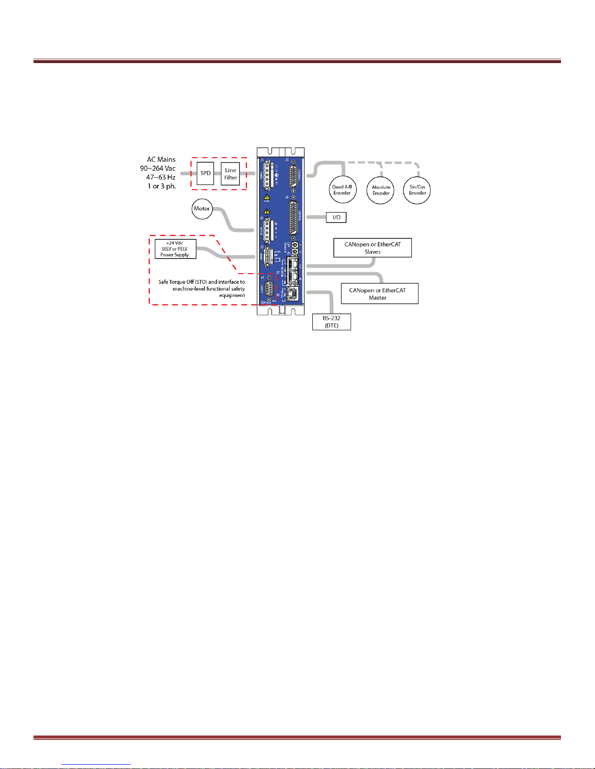
Fig. 1
3.4 Installation Overview
This graphic shows all of the elements in a complete Xenus Plus Compact installation. The STO feature and
interface to the machine-level functional safety equipment are highlighted in red to emphasize the aspects of the
installation that are addressed in this manual.
A UL RC (Recognized Component) SPD (Surge Protective Device) type 1CA, 2CA, 3CA or a UL Listed (VZCA) SPD type 1,
2, or 3 rated 2500 V, with a minimum SCCR of 5 kA, 240 Vac, and surge voltage monitoring needs to be provided. The
purpose of the SPD is to establish an OVC II environment. Example parts are Cooper Bussman BSPM3240DLG (3 phase)
or BSPM2240S3G (two-pole). Alternatively, an isolation transformer may be used between AC mains and the drive to
establish an OVC II environment.
3.5 Definitions
There are certain terms used throughout this document that serve an important role in describing the operation
and behavior of the Xenus Plus Compact STO feature. These terms are discussed and defined as follows:
Activate – This term is used to refer to action taken that results in the safe state being entered. In the case of
the STO feature, the STO function is activated (made active) by making the voltage at one or both STO inputs
less than or equal to the maximum rated de-energize threshold voltage.
De-Activate – This term is used to refer to action taken that results in the safe state being exited. In the case of
the STO feature, the STO function is de-activated (made inactive) by making the voltage at both STO inputs
greater than or equal to the minimum rated energize threshold voltage.
Energize – This term refers to the application of voltage greater than or equal to the minimum rated energize
threshold voltage to an individual STO input. Note that simultaneously energizing both STO inputs results in the
STO function being de-activated.
De-Energize – This term refers to the application of voltage less than or equal to the maximum rated
de-energize threshold voltage to an individual STO input. Note that de-energizing an STO input results
in the STO function being activated.
Page 9 of 31 Copley Controls
Page 10
Xenus Plus Compact STO Manual 16-01553 Rev 00
EtherCAT
CANopen
Feedback
XEC-230-09
XPC-230-09
Encoder
XEC-230-12
XPC-230-12
XEC-230-15
XPC-230-15
XEC-230-09-R
801-1891
XPC-230-09-R
Resolver
XEC-230-12-R
801-1892
XPC-230-12-R
XEC-230-15-R
801-1893
XPC-230-15-R
Table 4
4.0 Introduction to the Xenus Plus Compact
4.1 Product Description
The Xenus Plus Compact models are intended to be operated from single or three phase power in the
100 Vac to 240 Vac range and can drive motor currents up to 15 Adc. These drives have a
Safe Torque Off (STO) function. When the STO function is activated, the ability to drive motor current is cut-off.
In the case of rotary motors, the torque produced by the motor is zero when the current is cut-off. In the case of
linear motors, the force produced by the motor is zero when the current is cut-off. The Safe Torque Off (STO)
function has been developed in accordance with IEC 61508, ISO 13849-1 and IEC 61800-5-2. The Xenus Plus
Compact is certified by UL as meeting the stated SIL Capability, Category and Performance Levels and other
requirements of the given standards. The Safe Torque Off (STO) function is realized in “hardware only” such
that no software, firmware, or programmable device is involved in the execution or reliability of the STO function.
4.2 Model Overview & Numbering
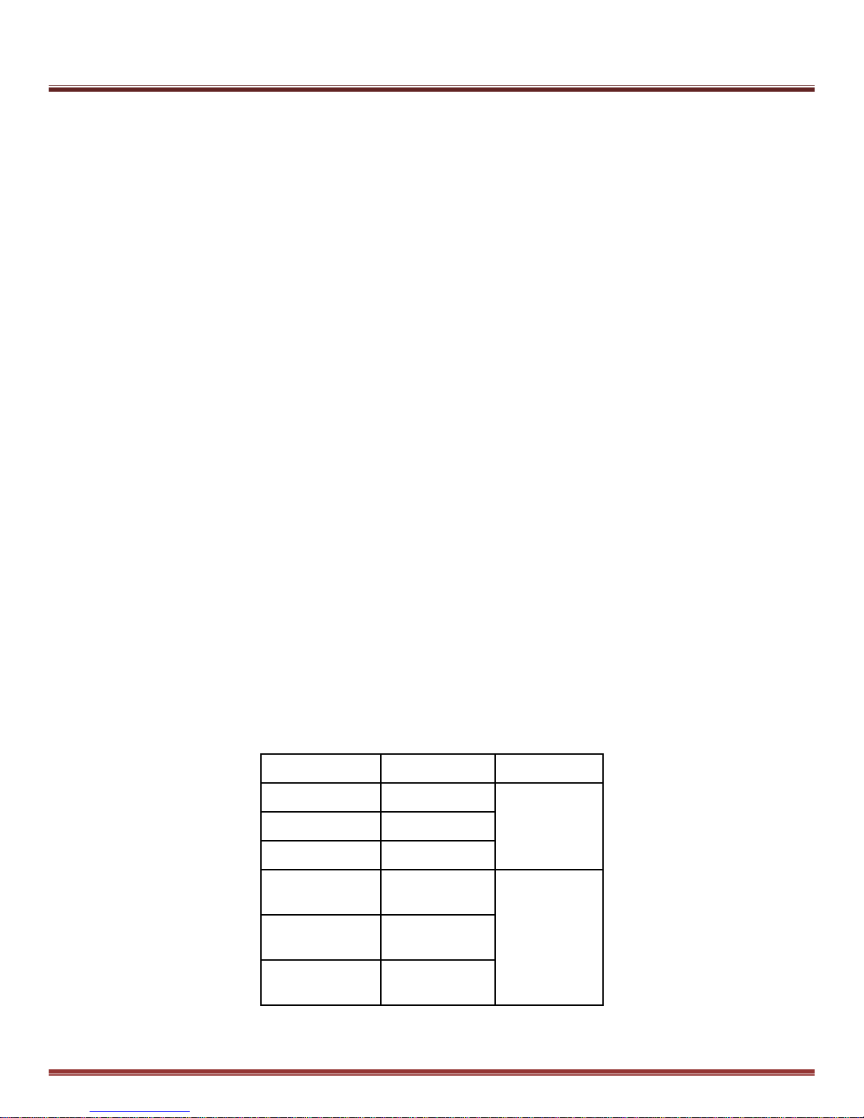
The Xenus Plus Compact models have the same electrical specifications and differ primarily in the
communications or the type of motor position feedback they support. XEC and 801-1891~1893 models work
with EtherCAT, and XPC models work with CANopen. Models with the ‘-R” suffix and the 801-1891~1893
models support resolver feedback whereas those without the “-R” suffix support encoder feedback.
All models have the same Safe Torque Off (STO) feature.
Note that as a convenience to customers Copley offers a certain level of customization to tailor Xenus Plus
Compact drives for a given application. This level of customization is most often limited to factory configuration
of user programmable parameters, but can include signal level hardware differences to accommodate less
common motor feedback devices. Drives with this customization carry the “Xenus Plus XEC” and “Xenus Plus
XPC” marking, but are assigned customer specific model numbers that begin with “800-“ followed by four or five
alphanumeric characters. These “800” number models have the same STO feature as the standard Xenus Plus
Compact models and are included within the scope of this manual.
The Xenus Plus Compact models are:
Copley Controls Page 10 of 31
Page 11

Xenus Plus Compact STO Manual 16-01553 Rev 00
5.0 Specifications Overview
5.1 Control Modes
Cyclic Synchronous Position-Velocity-Torque (CSP, CSV, CST in EtherCAT drives only)
Cyclic Synchronous Torque Mode with Commutation Angle (CSTCA in EtherCAT drives only)
Profile Position-Velocity-Torque, Interpolated Position, Homing (CANopen & EtherCAT drives)
Camming, Gearing
Indexer (Internal program execution)
5.2 Command Sources
XEC, 801-1891~1893: CANopen application protocol over EtherCAT (CoE)
XPC: CANopen
ASCII and discrete I/O
Stepper commands
±10V position/velocity/torque
PWM velocity/torque command
Master encoder (Gearing/Camming)
5.3 Power Sources
Mains voltage: 100~240 Vac, ±10%, 1 Ø or 3 Ø, 47~63 Hz
Over-Voltage Category: OVC III (An SPD or isolation transformer is required to
limit overvoltages to OVC II levels)
Maximum Mains Current: Model dependent – see the Xenus Plus Compact User Guide
Control Power +24 Vdc typical, +20 to +32 Vdc
The 24V is required for operation and powers the control core and communications in the drive.
Mains power may be removed and the drive can continue to communicate and report status via the
communication link as long as the 24 Vdc power is maintained.
Page 11 of 31 Copley Controls
Page 12
Xenus Plus Compact STO Manual 16-01553 Rev 00
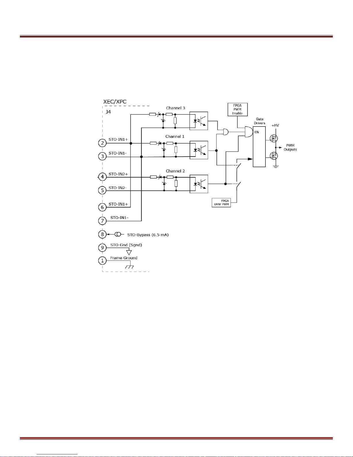
Fig. 2
6.0 STO Architecture and Function
The Xenus Plus Compact STO function is suitable for use in safety loops up to SIL 3 and/or Cat. 3 PL d
performance. The circuit concept uses a quasi three-channel architecture so that the safety function will
continue to operate even in the event of two failures. This architecture is shown in the system block diagram
below.
In the Safe State, the drive will not produce torque or force in the motor. The STO function achieves and
maintains a safe state by disabling the ability of the attached motor to produce torque/force. This both halts any
drive induced acceleration already in process and prevents initiation of motion. The expectation is that an
inability of the motor to produce torque/force translates into a reduction of risk of hazardous motion for the larger
system.
The STO circuit concept involves disabling the ability of the motor drive output stages to produce current. The
PWM outputs consists of three UVW totem-pole outputs, each composed of upper and lower IGBT devices.
The UVW PWM signals go to gate-drivers that control the upper and lower devices, producing current in the
motor windings which in turn can produce motion. STO channels 1 & 2 can cut-off the UVW PWM signals to the
gate drivers as a group.
Copley Controls Page 12 of 31
Page 13
Xenus Plus Compact STO Manual 16-01553 Rev 00
STO
STO
STO Function State
0
0
STO function is active , both inputs de-energized
1
0
STO function is active, one input de-energized
0 1 1
1
STO function is inactive, both inputs energized
Table 5
STO Channel 3 is ANDed with Channel 2 to disable the drive by disabling both the high and low side MOSFET
gate drives. Any of the three channels by itself is therefore sufficient to prevent the initiation of motion or halt
drive induced acceleration when the STO function is activated.
Each STO channel receives an input in the form of a voltage (typically +24 Vdc to energize and 0V or open to
deenergize) applied to STO_IN1 (+,-) and STO_IN2 (+,-). Note in figure 2 that STO_IN1 (+,-) drives two parallel
connected opto-coupler stages (Channel 1 and Channel 3). STO_IN2 (+.-) drives the opto-coupler stage for
Channel 2 only. Both STO inputs must be simultaneously energized in order for torque/force to be produced. To
achieve the rated SIL and PL capability, both STO inputs must be held simultaneously de-energized by the
larger system when the STO function is activated. In a typical machine application, each STO input is driven by
a +24 Vdc supply voltage switched through a safety relay. Note that the STO inputs are designed to withstand
input voltages to +60 Vdc to provide a measure of overvoltage protection. By definition, the output of an SELV
rated power supply is a maximum of +60 Vdc in a fault condition. Therefore a constraint on the larger system is
that the power supply used to energize the STO inputs must be an SELV type.
6.1 STO Channel Operation
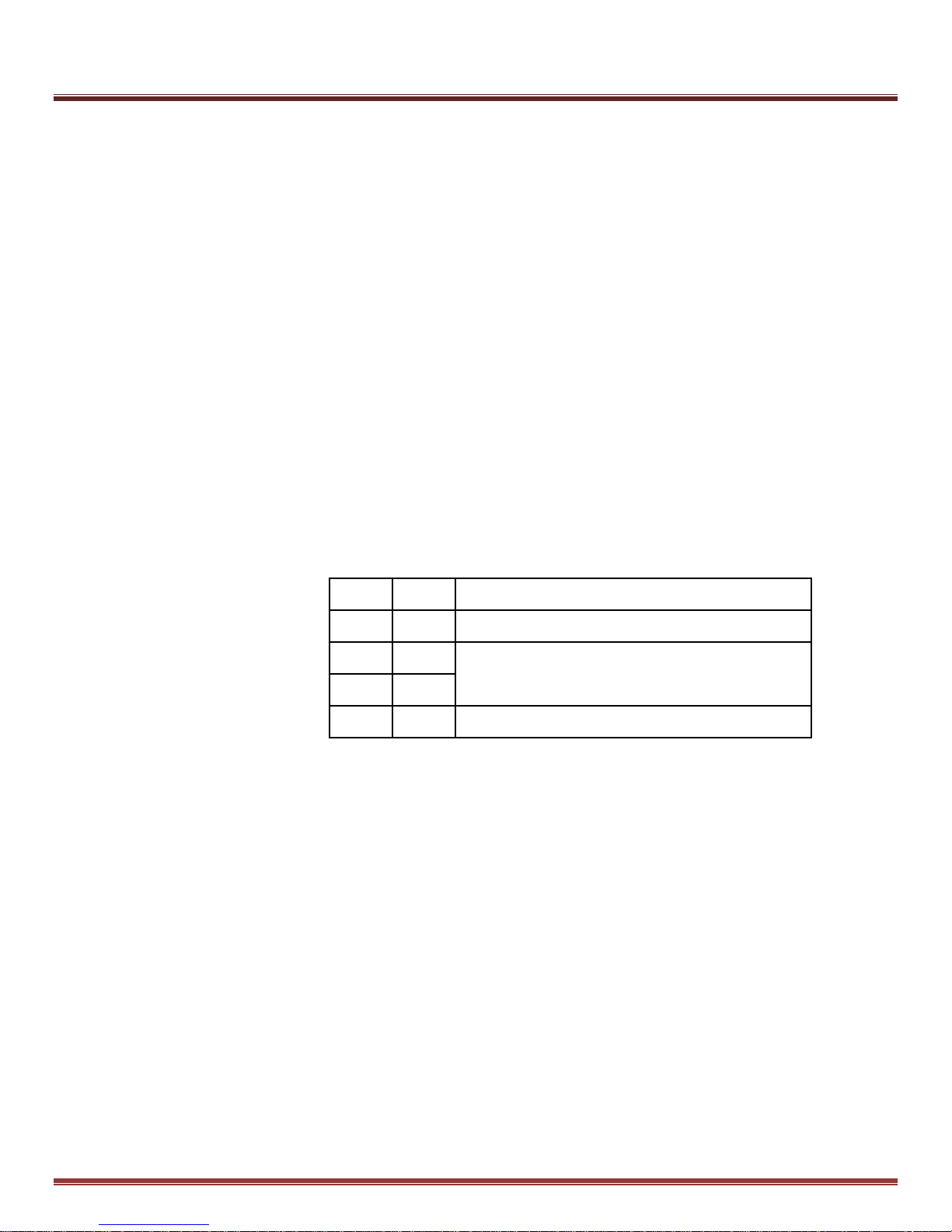
STO Function Active = No force/torque production is possible in motor
STO Function Inactive = Force/torque production in motor is under control of the drive
The table above shows the operation of the STO channels.
0 = Voltage applied to the STO input is less than or equal to the rated maximum de-energize level.
1 = Voltage applied to the STO input is greater than or equal to the rated minimum energize level.
A motion control system design for Cat. 3 PL d, and/or SIL 3 rating must use 2 channels for the STO function.
Page 13 of 31 Copley Controls
Page 14
Xenus Plus Compact STO Manual 16-01553 Rev 00
Specification
Requirement
Operation
When STO is active, motor current that can cause rotation (or motion in the
case of a linear motor) is not applied. The PWM outputs are disabled and
cannot source or sink current. This STO function is defined in IEC-61800-52, clause 4.2.2.2
Standards Conformance
IEC-61508-1, IEC-61508-2, IEC-61800-5-2, ISO 13489-1
Safety Integrity Level
SIL 3
Category & Performance Level
Category 3, Performance Level PL d
Implementation
Hardware only – Type A components
Systematic Capability
SC 3
Certifications
UL Functional Safety Mark (Pending)
Signals (Functional Safety
Related)
STO-IN1(+), STO-IN1(-), STO-IN2(+), STO-IN2(-), Frame ground (shield)
Signals (for muting)
STO-Bypass, STO-Gnd
STO Input Energize
Voltage Level
Vin-HI ≥ +15.0 Vdc between STO-IN(+) and STO-IN(-)
STO Input De-energize
Voltage Level
Vin-LO ≤ +6.0 Vdc or open between STO-IN(+) and STO-IN(-)
Input current (typical)
STO-IN1: 11.2 mA, STO-IN2: 11.2 mA
Current flow is into STO-IN1(+) and STO-IN2(+) and out of STO-IN1(-) and
STO-IN2(-). STO inputs must not be connected in series.
Response Time
From Vin ≤ 6.0 Vdc or open to STO Activated : 2 ms
Type
Opto-isolators, 24V compatible
Maximum cable length
30 m (98.4 ft)
Specification
Requirement
Operating Temperature
0 °C to 45 °C per IEC 60068-2-1:2007 and IEC 60068-2:2007
Operating Humidity
0 to 95 %RH, non-condensing per IEC 60068-2-78:2001
Storage Temperature
-40 °C to 85 °C per IEC 60068-2-1:2007 and IEC 60068-2-2:2007
Altitude
≤ 2000 m per IEC 60068-2-13:1983 or ≤ 4000 m if an isolation transformer
is used to establish an OVC II environment.
Contaminants
Pollution Degree 2 per IEC 60664-1:2007
Mechanical Shock
10g, 10 ms, 1/2 Sine Pulse per IEC 60068-2-27:2008
Vibration
2g, peak, 10~500 Hz (Sine) per IEC 60068-2-6:2007
Table 6
Table 7
6.2 STO Function Specifications
6.3 Environmental Specifications
Copley Controls Page 14 of 31
Page 15
Xenus Plus Compact STO Manual 16-01553 Rev 00
IEC 61508: 2010
ISO 13849-1: 2015
SIL 3 HFT
2 PL
d
Category
3
PFH
6.5 x 10
-9
SFF
< 60%
CCF
80
MTTFD
100
yrs
PFD
5.7 x 10
-4
PTI
20 yrs
DC
avg
61%
Specification
Requirement
Approvals
UL recognized component to UL 61800-5-1
UL Functional Safety to IEC 61508 and ISO 13849-1
Functional Safety
IEC 61508-1:2010, IEC 61508-2:2010, ISO 13849-1:2015, ISO 13849-2:2003,
IEC 61800-5-2:2007
Electrical Safety
Directive 2014/35/EU – Low Voltage, IEC/UL/CSA 61800-5-1:2007
EMC
Directive 2014/30/EU - EMC
Emissions: IEC 61800-3:2004 + A1: 2011, Category C3
Immunity: IEC 61800-3:2004 + A1:2011, Category C3
Functional Safety Immunity: IEC 61800-3:2004 + A1:2011
IFA “EMC and Functional Safety of PDS”, (Feb 2012)
Markings
• UL recognized component (Canada and US) <pending>
• CE
• UL Functional Safety <pending>
Hazardous
Substances
Lead free and RoHS compliant
Table 8
Table 9
6.4 Safety Related Parameters
6.5 Regulatory Specifications
Page 15 of 31 Copley Controls
Page 16

Xenus Plus Compact STO Manual 16-01553 Rev 00
6.6 Limitations and Necessary Risk Reductions
6.6.1 Electrical Isolation
The STO function does not provide electrical isolation between the drive and the motor.
Hazardous voltages may be present on the motor output terminal J2, even with the STO function activated.
6.6.2 DC Brush Motors
Failure of an IGBT in the outputs of the drive that renders the IGBT a virtual short-circuit might result in
continuous torque/force production in a DC motor. Unlike brushless motors that limit rotation to one half of an
electrical cycle, a DC brush motor can rotate uncontrollably under a failed IGBT scenario. As result, the STO
function cannot be used with DC brush motors.
6.6.3 180 Degree Electrical Movement
In the event of IGBT failures in the Xenus Plus Compact output stage, unexpected motor movement of up to
180 electrical degrees can occur. It is the responsibility of the designer of the larger system to assess and
address any hazards that this unexpected movement could create.
6.6.4 Loads and Other Torque/Force Producing Sources
The STO function produces an uncontrolled stop of category 0 as described in IEC 60204-1.
Any motor that is moving when the STO function is activated will coast to a stop unless there are other forces
operating on the same load. The STO function only removes torque/force produced by current flow from the
drive to the associated motor. Torque/force created by gravity-influenced loads or other torque/force
producing components mechanically connected to the motor shaft cannot and will not be affected by the
drive STO function. It is the responsibility of the designer of the larger system to assess and address any
hazards arising from torque/force producing sources.
6.6.5 STO Input Signal Level
The STO inputs (STO-IN1, STO-IN2) can withstand input voltages to 60V in case of an overvoltage fault
condition. Therefore a constraint on the larger system is that the power supply used to drive the STO inputs
must be a SELV or PELV type.
6.6.6 Control Modes and STO
The Xenus Plus Compact drive can control the position, velocity, and torque of motors while operating from a
number of control sources. But it can only do this when the STO function is inactive. And, while the digital
control core and firmware of the drive can observe the state of the STO function, it cannot interact with, or
exercise any control over the STO function.
The STO function operates completely independently of the control core of the drive and is
implemented entirely in hardware. It does not depend on the control core for its operation and the
control core of the drive has no control over the STO function.
Copley Controls Page 16 of 31
Page 17

Xenus Plus Compact STO Manual 16-01553 Rev 00
6.6.7 24V DC Power Supply
A constraint on the larger system is that the power supply used to provide the 24V control power to the drive
must be a SELV or PELV type.
6.6.8 AC Mains Over-Voltage Category
The AC mains supplying the drive must be limited to over-voltages of Category II. The relevant standards
assume AC mains with over-voltages per OVC III. An SPD or isolation transformer is required to
limit over-voltages to OVC II levels.
6.6.9 Wiring to the STO Inputs
Electrical connections to the STO inputs must meet the requirements for fault exclusions for short circuits
between conductors and short circuits between conductors and other conductive parts or earth or the
protective bonding conductor. Fault exclusion requirements are given in ISO 13849-2 and IEC 61800-5-2.
Toward this end, the STO cable connector is a crimp and poke type in order to meet the relevant fault
exclusions. The contacts and connector provide spacing that is greater than the minimum creepage and
clearance of 1.24 mm that is required for fault exclusion when considering the FMEDA (Failure Modes,
Effects, and Diagnostic Analysis) of the system.
6.6.10 Periodic Test Requirements
In order to meet the diagnostic coverage requirements for Cat. 3 PL d, the STO function must be checked at
least once per year. See section 9 for specific details.
Page 17 of 31 Copley Controls
Page 18
Xenus Plus Compact STO Manual 16-01553 Rev 00
Fig. 3
7.0 Installation Using STO for Xenus Plus Compact
7.1 STO Wiring Overview
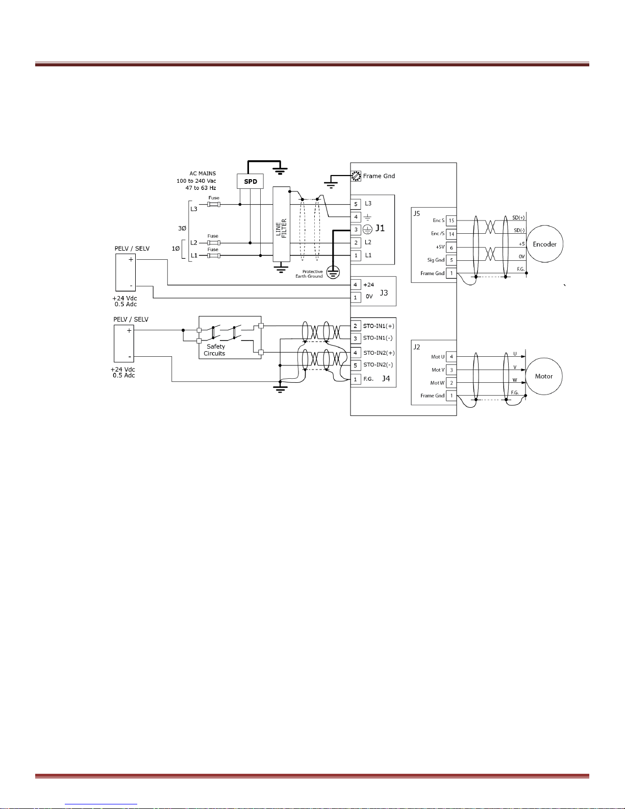
This diagram gives detail on the physical cabling, shielding, and grounding of the wiring between the
drive STO inputs and the machine level safety circuits.
7.1.1 STO Power Requirements
The 24V power supply for the STO inputs must be SELV or PELV rated.
The 24V power supply for the drive control power must be SELV or PELV rated.
7.1.2 STO Wiring Requirements
Electrical connections to the STO inputs must meet the requirements for fault exclusions for short circuits
between conductors and short circuits between conductors and other conductive parts or earth or the
protective bonding conductor.
These requirements are given in ISO 13849-2 and IEC 61800-5-2.
Toward this end, the DB-9 mating connector for making connections to the STO inputs must be a crimp and
poke type in order to meet the relevant fault exclusions.
A solder-cup style must not be used.
Copley Controls Page 18 of 31
Page 19
Xenus Plus Compact STO Manual 16-01553 Rev 00
Fig. 4
STO Cable Connector
STO Receptacle J4
STO J4 on Drive
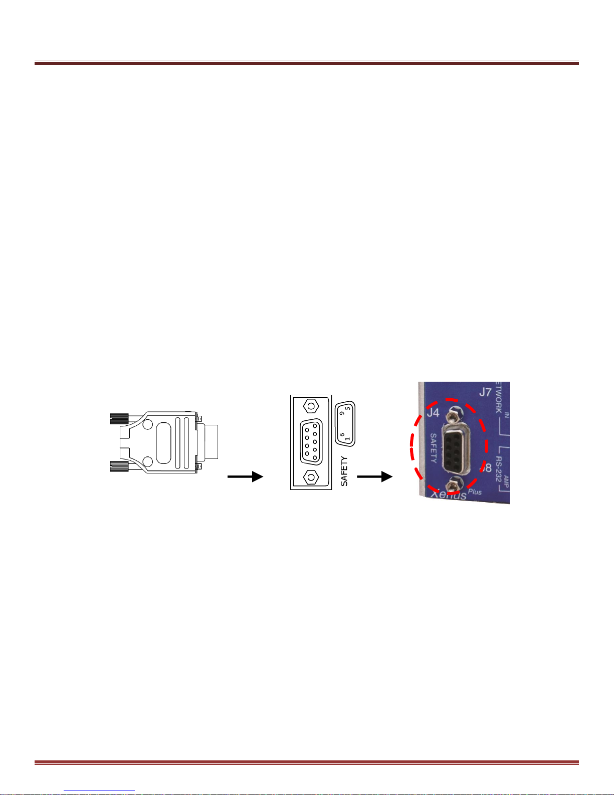
7.1.3 STO (Safety) Cable Connector
The Xenus Plus Compact STO connector J4 is a Kycon K22X-E9S-N. It is a Dsub-9F receptacle with gold-flash
plating on the pins and #4-40 standoffs which can receive male jack-screws on the cable connector.
The mating cable connector must have crimp and poke contacts with gold flash or plating and jack-screws.
Solder-cup contacts do not have the minimum 1.24 mm spacing to meet the functional safety requirements and
must not be used.
This is an example of a cable connector that is suitable for the Xenus Plus Compact STO:
Housing: AMP Tyco PN 205204-4, D-Sub-9M, tin plated, crimp contacts
Contacts: AMP Tyco PN 66506-9, stamped, male, 10 micron gold, AWG 20-24
Backshell: 3M PN 3357-9209, metalized plastic with thumbscrews
Other types may be suitable as long as they have crimp and poke contacts with gold flash or plating,
jack-screws for retention, and spacings adequate for fault exclusion.
Page 19 of 31 Copley Controls
Page 20
Xenus Plus Compact STO Manual 16-01553 Rev 00
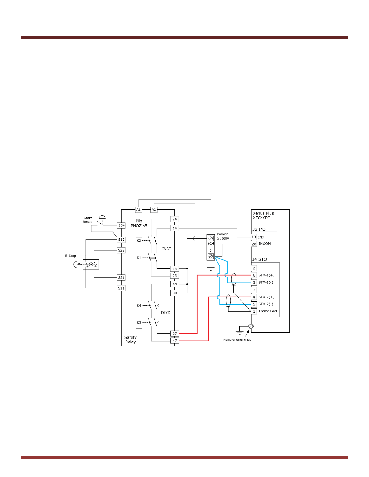
Fig. 5
7.1.4 Wiring Example:SIL 3/Cat. 3 PL d Emergency Stop - Stopping Category 1
Figure 5 below shows a wiring example for implementing a SIL3, Cat. 3 PL d, category 1 emergency stop
function using a Xenus Plus Compact. This type of implementation brings the motor speed to near zero before
the STO function is activated. It is important to note that the safe state is not entered immediately upon
actuation of the E-stop button. The safe state is entered only after the STO inputs have become de-energized
and the specified STO response time has elapsed.
The example shows a safety relay with two sets of output contacts – one set (K1, K2) responds immediately to
changes on the safety relay inputs and the other (K3, K4) after a user switch-programmable delay. A double
pole, single throw E-stop switch is used to drive two independent inputs to the safety relay. A momentary switch
is wired to the safety relay reset input and is used to reset the relay at start-up and after an E-stop event. The
enable input on the drive is wired to one of the immediate (INST) response contacts. The drive is programmed
such that when this input is de-energized, the drive decelerates the motor speed in a controlled fashion. After
the programmed delay time, contacts K3 and K4 open and de-energize the STO inputs to the drive. The drive
STO function responds accordingly and the safe state is entered within the specified drive STO response time.
7.1.5 Xenus Plus Compact Configuration
IN7 is an opto-isolated input that is programmed to Enable the drive. The INCOM signal for IN7 connects to
ground. When 24V is applied to IN7 it will enable the Xenus Plus Compact if no other inputs are configured as
Enables and no Enable inputs are inactive. If more than one input is configured as Enable, then all must be
active in order to enable the drive. The PNOZ s5 relay uses both contacts of the delayed relay (DLYD) for twochannel control of the STO function, which is necessary for SIL 3, Cat. 3 PL d.
Copley Controls Page 20 of 31
Page 21
Xenus Plus Compact STO Manual 16-01553 Rev 00
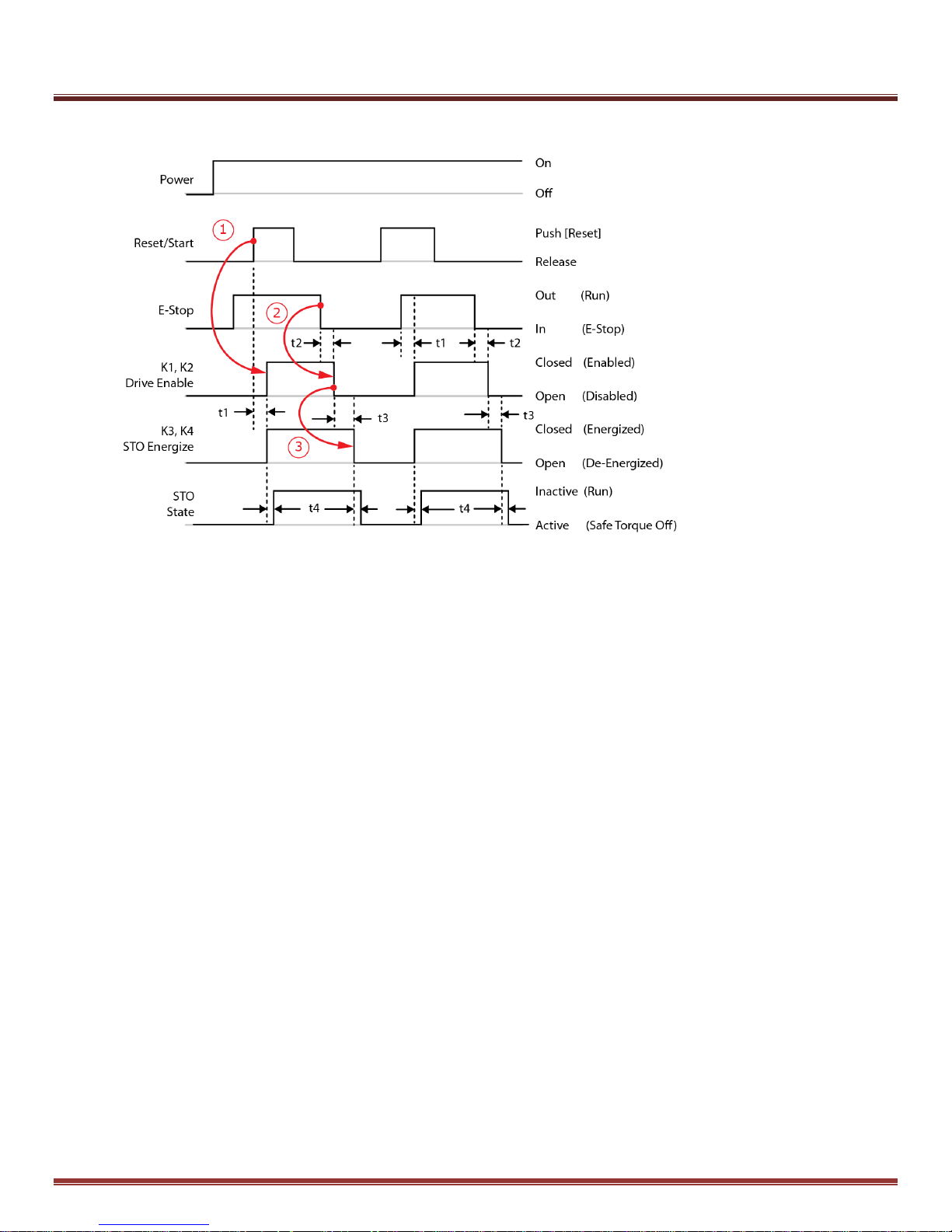
Fig. 6
7.1.6 Example STO Timing
Power +24 VDC supplied to the safety relay
Reset/Start Momentary push-button that causes the K1~K2 relay contacts to close, supplying power
to the STO inputs of the drive, and de-activating the STO function.
This allows the drive to produce torque/force in the motor when it is enabled.
E-Stop The latching push-button switch inputs to the safety relay. The HI level of this indicates
that the button has been released, opening the NC (Normally Closed) contacts.
K1, K2 The instantaneous contacts in the relay. A HI level indicates that the contacts are closed,
supplying power to an Enable input of the drive to place it in an enabled state.
K3, K4 Relay contacts that will open after a pre-set time delay. This allows time for the drive
to remain in an enabled state while it performs a controlled deceleration that brings
the motor to a standstill before the STO function is activated,
preventing any torque/force production in the motor.
t1 Switch-on delay. If the E-Stop button is out, this is the delay after the Reset/Start button is
pressed in and the K1~K4 relay contacts close, deactivating the STO function and
enabling the drive (1).
t2 Delay-on de-energization. When the E-Stop button is pressed in (E-Stop), this is the delay to
the opening of the K1~K2 contacts which disables the drive, initiating a controlled
deceleration of the motor (2).
t3 Waiting period. This is the time-delay that allows for the controlled deceleration of the motor.
When the E-Stop button is pressed in, this is the time delay to the K3~K4 contact opening
which will activate the STO (3).
t4 STO response time. This is the time between the de-energizing of the drive STO inputs
(K3~K4 contacts open) and the entry into the safe-state.
Page 21 of 31 Copley Controls
Page 22

Xenus Plus Compact STO Manual 16-01553 Rev 00
7.2 Start-Up Checklist
Proper operation of a safety function must be validated at various points in the
product lifetime of the end-use machine.
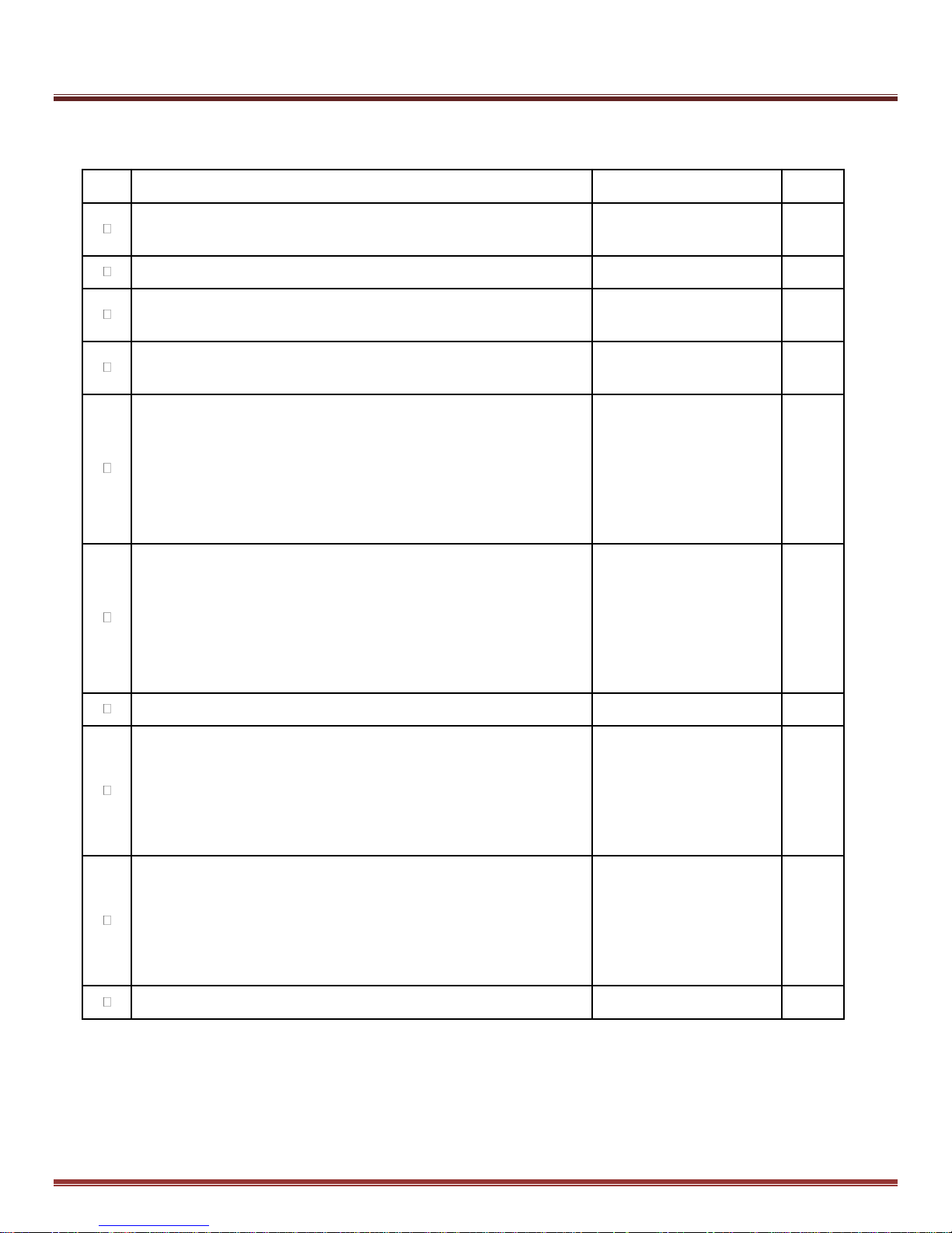
Validation tests, in accordance with the checklist given as table 10 must be conducted by an authorized
person experienced in the functional safety of machines. Validation tests must be conducted:
• At initial installation and start-up of the safety function.
• After any changes related to the safety function (wiring, components, settings, etc.)
• After any maintenance work related to the safety function.
• At the required periodic test intervals.
7.2.1 Preliminary checks
Before powering the drive, and commencing with the functional safety tests, check:
• That the installation requirements given in the Xenus Plus Compact User Guide and this manual have
been adhered to. Specifically ensure that proper grounding, shielding, overcurrent, and overvoltage
protection measures are in place in regards to electrical safety and electromagnetic compatibility.
• That the wiring between the machine level safety circuits and the drive STO inputs meets the
requirements set forth in this manual and those in IEC 61800-5-2 and ISO 13849-1 for
wiring-associated fault exclusions.
• That the motor and associated loads are free to move.
• That any other safety measures or warnings needed to ensure safe execution of
validation tests are in place.
Copley Controls Page 22 of 31
Page 23
Xenus Plus Compact STO Manual 16-01553 Rev 00
Chk
Requirement
Comments
Initials
Ensure that the drive can be run and stopped freely during the
commissioning.
Stop the drive (if running), and safely remove AC power from the drive.
Check the STO-IN1 and STO-IN2 circuits and connections against a
wiring diagram.
Apply AC mains power to the drive. Energize both the STO-IN1 and
STO-IN2 circuits.
Test the operation of the STO-IN1 function when the motor is stopped.
Give a stop command for the drive (if running) and wait for the motor to
come to a standstill.
While keeping STO-IN2 energized, de-energize the STO-IN1 circuit and
give a start command for the drive. Ensure that the motor remains at a
standstill.
Energize the STO-IN1 circuit.
Test the operation of the STO-IN2 function when the motor is stopped.
Give a stop command for the drive (if running) and wait for the motor to
come to a standstill.
While keeping STO-IN1 energized, de-energize the STO-IN2 circuit and
give a start command for the drive. Ensure that the motor remains at a
standstill.
Energize the STO-IN2 circuit.
Restart the drive and check that the motor runs normally
Test the operation of the STO-IN1 function when the motor is running:
Start the drive and ensure that the motor is running. While keeping
STO-IN2 energized, de-energize the STO-IN1 circuit. Ensure that the
motor stops. Reset any latching fault that may have occurred (these
depend on the drive’s control mode settings). Try to start the drive.
Ensure that the motor stays at a standstill. Energize the STO-IN1 circuit
Test the operation of the STO-IN2 function when the motor is running:
Start the drive and ensure that the motor is running. While keeping
STO-IN1 energized, de-energize the STO-IN2 circuit. Ensure that the
motor stops. Reset any latching fault that may have occurred (these
depend on the drive’s control mode settings). Try to start the drive.
Ensure that the motor stays at a standstill. Energize the STO-IN2 circuit
Restart the drive and ensure that the drive and motor operate normally.
Table 10
7.2.2 Start-Up Checklist
Page 23 of 31 Copley Controls
Page 24
Xenus Plus Compact STO Manual 16-01553 Rev 00
Bit
Safety Circuit Status
0
True (1) when STO-IN1 is de-energized and STO is active
1
True (1) when STO-IN2 is de-energized and STO is active
Table 11
Fig. 7
7.3 STO Status Indications
Although they are not and must not be considered part of the safety function, indications of the STO
status are available from the Xenus Plus Compact drive for convenience purposes.
Specifically the J8 LED, two user-accessible data objects bits, and the CME2 Control Panel provide
some information on STO status. The LEDs, data objects, and CME2 are not part of the drive safety
function.
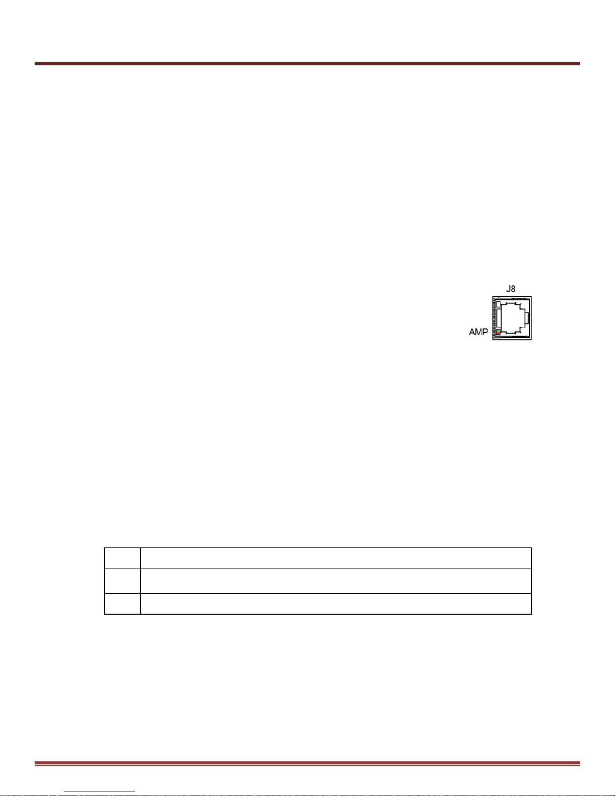
7.3.1 J8 AMP LED
A bi-color LED gives the state of the drive. Colors do not alternate, and can be solid ON or blinking. When
multiple conditions occur, only the top-most condition will be displayed.
When that condition is cleared the next one below will shown.
Red/Blinking = Latching fault. Operation will not resume
until drive is Reset
Red/Solid = Transient fault condition. Drive will resume
operation when the condition causing
the fault is removed.
Green/Double-Blinking = STO circuit active, drive outputs are
Safe-Torque-Off
Green/Slow-Blinking = Drive OK but NOT-enabled. Will run when enabled.
Green/Fast-Blinking = Positive or Negative limit switch active.
Drive will only move in direction not inhibited
by limit switch.
Green/Solid = Drive OK and enabled. Will run in response to
reference inputs or communication commands.
7.3.2 STO Circuit Status Data Objects
The Xenus Plus Compact has a variety of data objects that can be read by the end user via CANopen,
EtherCAT, or serial communications. The status of the STO circuit is available in ASCII parameter 0x139 and
DS-402 parameter 0x219D. Bits 0 & 1 show the status of the STO-IN1 and STO-IN2 inputs.
Bit 8 has no function in the Xenus Plus Compact.
Copley Controls Page 24 of 31
Page 25
Xenus Plus Compact STO Manual 16-01553 Rev 00
Fig. 8
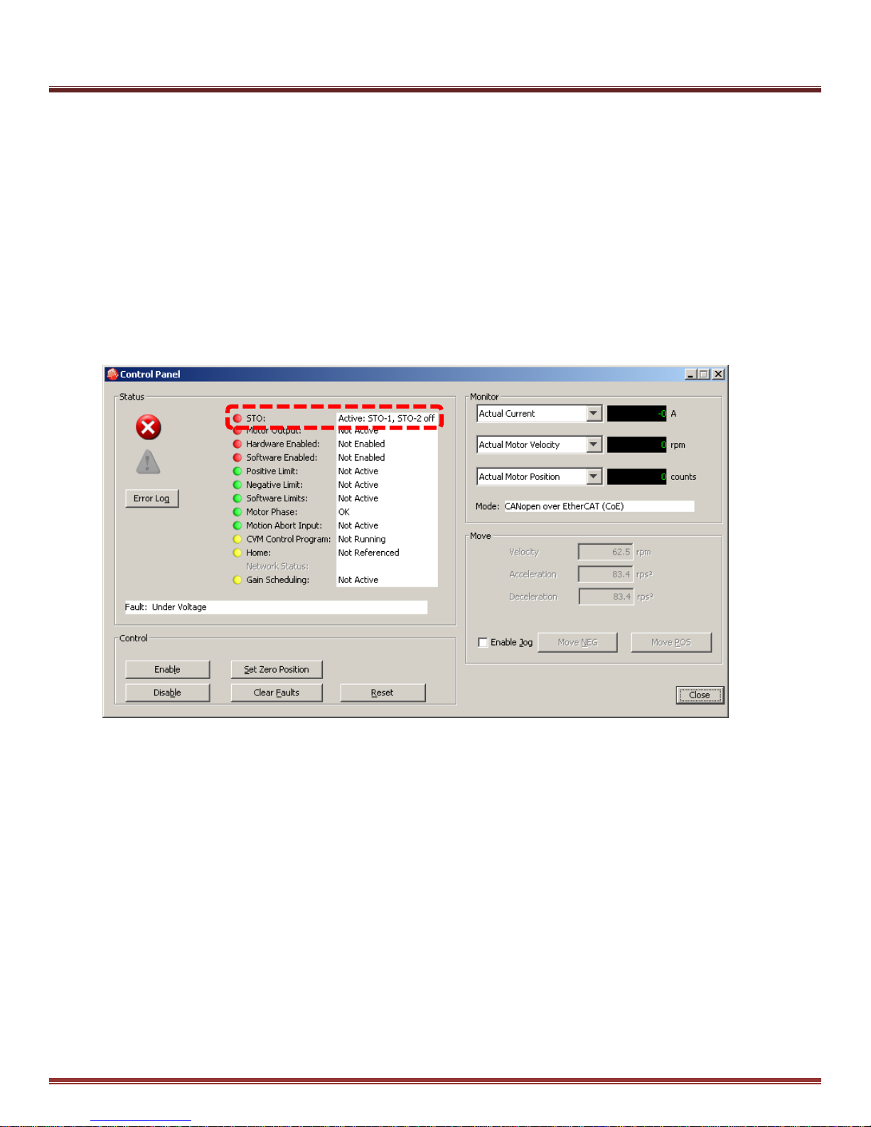
7.3.3 CME2 Control Panel
CME2 is the PC based software tool used for configuring, commissioning, and troubleshooting Copley Control
digital servo drives. A graphic LED labeled “Safety” on the CME2 Control Panel screen gives the status of the
STO function.
Green = STO inactive. Torque production in the motor is under user control.
Red = STO active. Drive outputs are Safe-Torque-Off
In the screen capture below the Safety (STO) LED is red, indicating that the STO function is active. The
message in the box to the right “Active: STO-1, STO-2 off” refers to the STO channels, both of which are unpowered, activating the STO function.
Page 25 of 31 Copley Controls
Page 26

Xenus Plus Compact STO Manual 16-01553 Rev 00
7.4 Troubleshooting
The status of the STO function in the Xenus Plus Compact drive can be viewed via LED indicators on the drive,
data objects accessible over CANopen, EtherCAT, and the configuration software CME2.
Other Copley software products such as CMO (Copley Motion Objects), CML (Copley Motion Libraries),
CPL (Copley Programming Language) and ASCII communications can read the status of the STO function.
The LED indicators and data parameters are not part of the drive safety function. They are informational
only, and cannot be relied upon for any safety related functions of the user.
7.4.1 How to tell if the STO function is active
The voltage to one or both of the STO channels in the drive is < 6 Vdc, or open.
The Amp LED on J8 double-flashes green, then pauses.
This pattern repeats when the STO function is active.
Bit 0 OR bit 1 of ASCII parameter 0x139 (DS-402 0x219D) is set (1).
The Safety LED on the CME2 Control Panel is red when the STO function is active.
For both EtherCAT and CANopen models, Bit 2 of the CANopen Status Word 0x6041 is zero, indicating
a hardware-disabled state. This bit is controlled by any input that is programmed for the Enable function,
and by the STO function. When bit is zero, then it is necessary to check 0x219D (ASCII 0x139) to see if
bit 0 or bit 1 is set (1). If this condition is true, then the STO function is active.
7.4.2 How to tell if the STO function is inactive
The voltage applied to both STO inputs of the drive is ≥ 15 Vdc.
The Amp LED on J8 is solid green or slow-blinking green.
Bit 0 AND bit 1 of ASCII parameter 0x139 (DS-402 0x219D) are zero.
The Safety LED on the CME2 Control Panel is green when the STO function is inactive.
For the EtherCAT and CANopen models, Bit 2 of the CANopen Status Word is set(1), indicating a
hardware-enabled state. The drive cannot be hardware-enabled until all inputs programmed as Enable
inputs are true AND the bits 0 AND bit t in the STO function status parameter (0x219D) are zero.
7.4.3 Why can’t the STO function be deactivated?
The voltage between STO-IN1(+) and STO-IN1(-) is < 15 Vdc OR the voltage between STO-IN2(+) and
STO-IN2(-) is < 15 Vdc. Both of these voltages must be ≥ 15 Vdc to deactivate the STO function
7.4.4 Why can’t the STO function be activated?
The voltage between STO-IN1(+) and STO-IN1(-) is > 6 Vdc AND the voltage between STO-IN2(+) and
STO-IN2(-) is > 6 Vdc. One or both of these voltages must be < 6.0 Vdc or the to activate the STO
function
7.4.5 The drive is hardware-enabled but the motors don’t move.
The STO function may be active. Check the Amp LED to see if it is double-flashing green.
If so, then the STO function is active. If not, check the Amp LED blink patterns for indications of other
faults or conditions that may inhibit motion.
Copley Controls Page 26 of 31
Page 27

Xenus Plus Compact STO Manual 16-01553 Rev 00
8.0 Maintenance
8.1 Accessibility and Replacement of Internal Parts
There are no user-replaceable parts in the Xenus Plus Compact. The warranty will be void if the user
removes the cover or attempts any repairs. For safety and to assure compliance with documented system
data, only Copley Controls shall perform repairs to the Xenus Plus Compact.
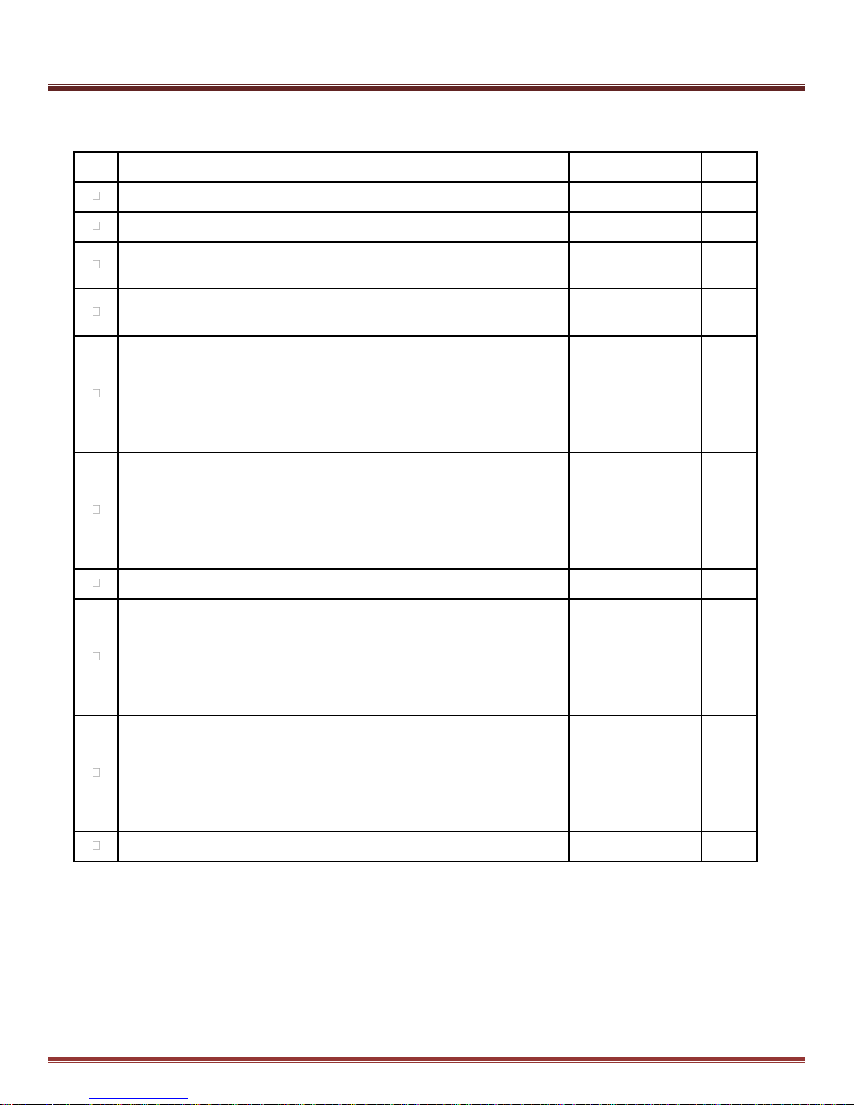
8.2 Periodic STO Testing Interval
In order to meet the diagnostic coverage requirements corresponding to Cat. 3 PL d, the STO function must
be tested at least once per year. The required test methodology is provided in checklist form in Table 12.
Page 27 of 31 Copley Controls
Page 28
Xenus Plus Compact STO Manual 16-01553 Rev 00
Chk
Requirement
Comments
Initials
Ensure that the drive can be run and stopped freely during the commissioning.
Stop the drive (if running), and safely remove AC power from the drive.
Check the STO-IN1 and STO-IN2 circuits and connections against a wiring
diagram.
Apply AC mains power to the drive. Energize both the STO-IN1 and STO-IN2
circuits.
Test the operation of the STO-IN1 function when the motor is stopped. Give a
stop command for the drive (if running) and wait for the motor to come to a
standstill.
While keeping STO-IN2 energized, de-energize the STO-IN1 circuit and give a
start command for the drive. Ensure that the motor remains at a standstill.
Energize the STO-IN1 circuit.
Test the operation of the STO-IN2 function when the motor is stopped. Give a
stop command for the drive (if running) and wait for the motor to come to a
standstill.
While keeping STO-IN1 energized, de-energize the STO-IN2 circuit and give a
start command for the drive. Ensure that the motor remains at a standstill.
Energize the STO-IN2 circuit.
Restart the drive and check that the motor runs normally
Test the operation of the STO-IN1 function when the motor is running: Start the
drive and ensure that the motor is running. While keeping STO-IN2 energized,
de-energize the STO-IN1 circuit. Ensure that the motor stops. Reset any
latching fault that may have occurred (these depend on the drive’s control
mode settings). Try to start the drive. Ensure that the motor stays at a
standstill. Energize the STO-IN1 circuit
Test the operation of the STO-IN2 function when the motor is running: Start the
drive and ensure that the motor is running. While keeping STO-IN1 energized,
de-energize the STO-IN2 circuit. Ensure that the motor stops. Reset any
latching fault that may have occurred (these depend on the drive’s control
mode settings). Try to start the drive. Ensure that the motor stays at a
standstill. Energize the STO-IN2 circuit
Restart the drive and ensure that the drive and motor operate normally.
Table 12
8.3 Periodic Testing Checklist
Copley Controls Page 28 of 31
Page 29
Xenus Plus Compact STO Manual 16-01553 Rev 00
From
To 2 4 3 5 6 8 7 9
Fig. 10
Fig. 9
Table 13
Fig. 10
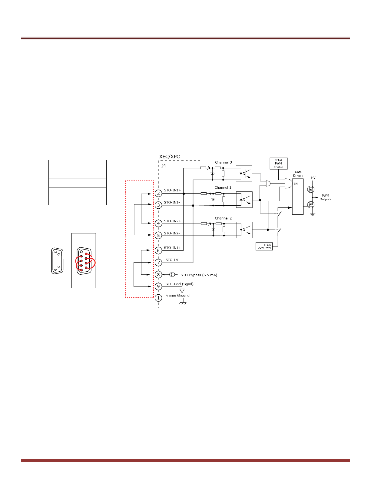
9.0 Muting & Suspension of Safety Functions
9.1 STO Muting
Muting means de-activating the STO function. A convenient method for muting the STO function is provided
for those applications not using the STO function.
An internal power source in the drive is brought out to the Safety connector J4. Connecting the STO inputs
between this bypass power source and its ground supplies power to the STO opto-couplers allowing the
PWM outputs to be controlled by the drive. Figure 10 below shows the muting connector circuit, table 13 lists
the jumper connections, and fig. 9 shows the jumper locations.
Muting Connector Wiring (J4)
From J4-pin to J4-pin
Page 29 of 31 Copley Controls
Page 30

Xenus Plus Compact STO Manual 16-01553 Rev 00
10.0 Decommissioning
Before decommissioning any safety system from active service:
Evaluate the impact of decommissioning on adjacent operating units and facilities or other field services.
Conduct a proper review and obtain required authorization.
Ensure that the safety functions remain appropriate during decommissioning activities.
Implement appropriate change management procedures for all decommissioning activities.
Copley Controls Page 30 of 31
Page 31

Xenus Plus Compact STO Manual 16-01553 Rev 00
Xenus Plus Compact STO Manual
P/N 16-01553
Revision 00
September 12, 2016
2016
Copley Controls
Analogic Motion Controls
20 Dan Road
Canton, MA 02021 USA
All rights reserved
Page 31 of 31 Copley Controls
 Loading...