


User Guide
Digital Servo Amplifier
Models 7228AC, 7228DC, 7428AC, 7428DC

Table Of Contents
Chapter 1 Introduction ......................................................... 1-1
Features ............................................................. 1-2
Models ................................................................ 1-3
Applications ........................................................ 1-3
Copley Motion Explorer Software ........................ 1-4
Software Requirements ....................................... 1-4
Terminology ........................................................ 1-5
CE Mark and UL Conformity ............................... 1-6
Unpacking and Inspection ................................... 1-7
Technical Support ............................................... 1-7
Safety ................................................................. 1-8
Chapter 2 Amplifier Connections ......................................... 2-1
Grounding ........................................................... 2-3
J1 AC & DC Power and Motor Phase ................. 2-4
DC Model Power Connections ............................ 2-6
Motor Phase Wiring Connections ....................... 2-8
J2 Motor Signal Wiring Connections ................... 2-9
Amp-Enable, Limit anf Home Switch Input ........ 2-22
Data Connector J4 ............................................ 2-27
Amplifier Status Indicator .................................. 2-30
Signal Module ................................................... 2-31
7XX8 Series Digital Servo Amplifier User Guide
1-1

Chapter 3 Getting Started ................................................... 3-1
Starting Copley Motion Explorer ......................... 3-2
Installation using Copley Motion Explorer
Development Kit Motor ........................................ 3-6
Verifying Software Parameters ............................ 3-6
First Move ........................................................... 3-7
Enabling the Amplifier ......................................... 3-8
Initiate a Move with the Pendant ......................... 3-8
Homing Sequence .............................................. 3-9
Software Parameter Notes ................................ 3-11
Position Loop Tuning ........................................ 3-11
Installation Using a Copley Motor Data File
and a New Copley Motor ................................... 3-13
Installation Using a Vendor Specification
and Motor ......................................................... 3-17
Adjusting Calculated Motor Data ...................... 3-19
Encoder Checking ............................................ 3-21
Auto Phasing .................................................... 3-24
Algorithmic Phase Initialization ......................... 3-29
Chapter 4 Operating Modes ................................................ 4-1
Torque Mode ....................................................... 4-2
Position Mode .................................................... 4-6
Velocity Mode .................................................... 4-9
Digital Position Mode ........................................ 4-11
1-2
Introduction

Chapter 5 Using Copley Explorer Motion Controller ............. 5-1
Main Window ...................................................... 5-3
File Menu ........................................................... 5-4
View Menu .......................................................... 5-5
Amplifier Menu .................................................... 5-5
On-Line Connection Screen ................................ 5-5
Amp Setup Screen ............................................. 5-6
Amplifier Status Now! Screen ............................. 5-8
Preset Manager Screen .................................... 5-29
Motor Menu ...................................................... 5-31
Motor Data Screens .......................................... 5-31
Motor Data > Specification Screen ................... 5-32
Motor Data > Specification Feedback Screen ... 5-32
Motor Data > Specification Ratings Screen ...... 5-32
Motor Data > Specification Electrical Screen ... 5-35
Motor Data > Specification Mechanical Screen 5-36
Apply Motor Data Screen .................................. 5-32
Motor Temperature Sensor Screen ................... 5-40
Tools Menu ....................................................... 5-41
Tools > Trace Graph ......................................... 5-41
Tools > Options ................................................ 5-43
Tools > Options > Directories ........................... 5-44
Tools > Options > Directories ........................... 5-45
Tools > Download Firmware .............................. 5-46
Tools > Encoder Check .................................... 5-47
Tools > Auto Phasing ....................................... 5-48
Tools > Home Sequence .................................. 5-49
Diagnostics Menus ........................................... 5-50
Diagnostics > Comm Log ................................. 5-51
Diagnostics > Special ....................................... 5-53
Help Menu ........................................................ 5-54
Amplifier Explorer Window ................................ 5-56
Stop Motor Window .......................................... 5-57
Copley Virtual Machine ..................................... 5-58
7XX8 Series Digital Servo Amplifier User Guide
1-3

NOTES
1-4
Introduction

Copyright 2000 Copley Control Corporation. All Rights Reserved.
This manual, as well as the software described in it, is furnished
under license and may only be used or copied in accordance with the
terms of such license. The information in this manual is furnished for
informational use only, is subject to change without notice, and
should not be construed as a committment by Copley Controls Corpo-
ration. Copley Controls assumes no responsibility or liability for any
errors or inaccuracies herein.
Except as permitted by such license, no part of this publication may
be reproduced, stored in a retrieval system, or transmitted in any
form without prior written permission of Copley Control Corp.
Motion ExplorerMotion Explorer
Copley
Motion Explorer
Motion ExplorerMotion Explorer
Microsoft Windows 98 is a registered trademark of Microsoft Corpora-
tion.
Copley Controls Corp. makes no warranties, express or implied,
including without limitation the implied warranties of merchantability
and fitness for a particular product regarding the Copley Motion
Explorer software.
Written and designed by Copley Controls Corporation,
410 University Avenue, Westwood MA 02090.
Printed in the U.S.A.
is a trademark of Copley Controls Corp.
Revision 1.1

Chapter 1 Introduction
The 7XX8 Series of Digital Servo Amplifiers are high
performance, DSP (Digital Signal Processor) controlled
amplifiers. They control AC brushless motors with full
sinusoidal commutation. AC models operate directly from
AC mains. DC models operate from DC power sources,
which directly rectify the line. All models have full
isolation between signal and power stages. No power
transformers are required.
Built using surface-mount technology, these amplifiers
offer a full complement of features for AC brushless motor
control. All models use industry standard
±10V analog control signals for torque or velocity
control. A two-signal digital input takes step-motor
command pulses for position control:
In either CW/CCW or PLS/DIR format, or
from quadrature encoder A/B signals.
Digital preset inputs can be used to initiate 16 predefined
velocity, torque or position indexes.
A three phase MOSFET bridge output stage delivers
power in four-quadrants for smooth and efficient
bidirectional acceleration and deceleration of motors.
Windows software is used to configure the various gain
and current limit settings and to customize the amplifiers
for a wide range of loads and applications. Settings are
held in nonvolatile flash memory. Communication with the
7XX8 Series Digital Servo Amplifier User Guide
1-1

amplifier is done through an RS-232 port for easy
interface to most computers. Software settings permit
compensation over a wide range of load inductances to
maximize bandwidth with different motors. Individual peak
and continuous current limits allow high acceleration
without sacrificing protection against continuous
overloads.
All models are protected against output short circuits
(output to output and output to ground) and heatplate
overtemperature. With Reset input open, the amplifier will
latch off until powered-down or the Reset input is toggled.
If reset from such conditions is desired, the Reset input
can be momentarily connected to ground.
A red/green status LED speeds diagnostics when the
amplifier is put into operation.
Features
The Digital Servo Amplifier Model 7XX8 Servo works with
DSP controlled torque, velocity or position modes using
only encoder feedback from the motor. It is
programmable for S-curve and trapezoidal motion files.
You can select up to 16 preset modes using a PLC or
Logic Hi/Lo line.
1-2
Introduction
Other features include:
No transformer required. AC version operates
directly from AC mains, DC version operates from
rectified line, with full optical isolation between
signal and power stages.
RS-232 digital interface used to store all settings
in internal FLASH memory for selecting preset
modes.
Separate motor signal and control signal Sub-D
type connectors for simpler cabling.
Terminals for DC Buss connect to an external
regenerative energy dissipator.
Input for motor temperature sensor with settable
thresholds and logic to protect motor windings.
Command sources: Analog ±10V inputs, Digital
PLS/DIR, CW/CCW, Digital presets and
Data RS-232.
Fault protections: short circuits from output to
output, output to gnd, over/under voltage, motor or
amplifier overtem temperatur.
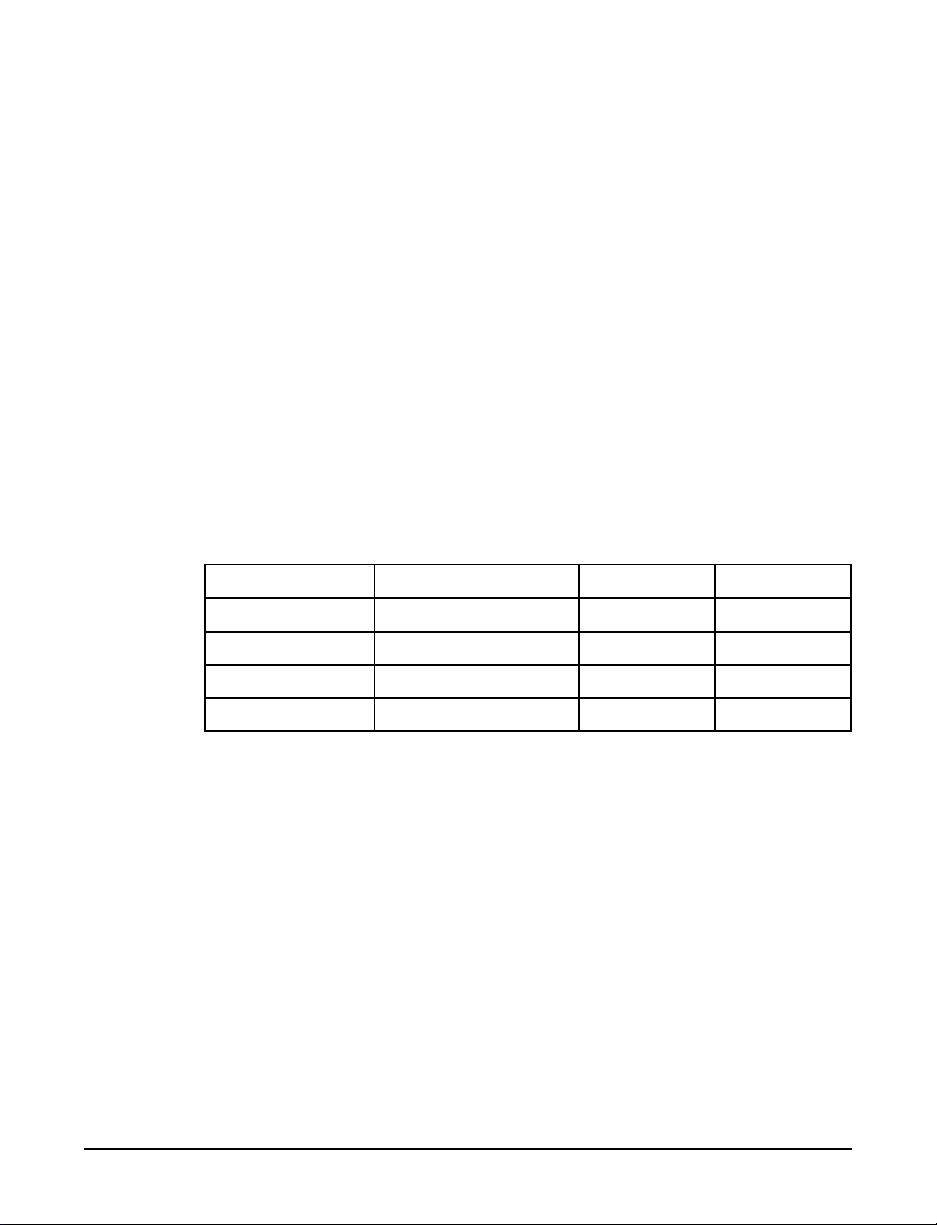
Models
The following table describes the 7XX8 Series Digital
Servo Amplifiers model variations.
ledoMegatloVkaeP-ItnoC-I
CA8227CAV231~230201
CA8247CAV462~230201
CD8227CDV681~540201
CD8247CDV373~540201
Table 1-1 7XX8 Models
Applications
The 7XX8 Series of Digital Servo Amplifiers are
compatible with a wide range of controllers. Applications
include:
Sinusoidal brushless motors
Linear brushless motors
X-Y stages
Robotics
Automated assembly machinery
7XX8 Series Digital Servo Amplifier User Guide
1-3

Motion Explorer Software
You can manage the 7XX8 Series of Digital Servo
Amplifiers from the Windows-based Copley Motion
ExplorerTM (CME) software. Some of the high level tasks
that you can perform from the CME screens include:
Create a new motor file, or load an existing
motor file.
Generate a new amplifier file, or load an existing
amplifier file.
Adjust motor phasing.
Fine tune current and position loops with trace
feature.
Select operating modes.
Generate new presets that you can store in
flash memory on the amplifier.
Execute diagnostics that display statistical or
graphical data about system performance.
1-4
Introduction
Software Requirements
The Copley Motion ExplorerTM software is
recommended for Windows 98 systems. The 7XX8 Series
Digital Servo Amplifier interfaces to a PC via a simple
RS-232 connection.
For more information about the Copley Motion
ExplorerTM software see Chapter 5.

Terminology
Some new terminology is introduced herein with this
product. The terms are defined below, and may be added
to as necessary.
mreTnoitinifeD
rotomdetaluclaC
atad
elif)rotom(mcc. tahtseulavetaluclacotatadelifacc.sesuEMC.atadrotomgniniatnocelifA
tnadneP ehtmorfslangisrorrednasutatsstpecretnidnasteserpstcelestahteludomA
rotomyranimilerP
atad
teserP otnoitamrofniehtllaniatnoctahtyromemHSALFniderotsseulavfotesA
rerolpxEnoitoMyelpoCybdetarenegatadrotomdnareifilpmafostsisnoC
.snoitacificepsrotomroselifmcc.rehtiemorfatadyranimilerpnodesab
elif)reifilpma(acc. .putesreifilpmadnasteserp61:seulavHSALFreifilpmallagniniatnocelifA
.atadteserpfotrapsayromemHSALFniderotsebnac
fosesopruproftnempiuqeresuafoecalpehtsekattI.sublangisehtnoreifilpma
.gubeddnatsetnoitacilppa
detaluclacneebsahtierofebnoitacificepsrotomaroelifmcc.arehtiE
yelpoCyb)deledom( .rerolpxEnoitoM
.elbaliavaerasteserp61otpU.reifilpmaehtetarepo
Table 1-2 New Terms
7XX8 Series Digital Servo Amplifier User Guide
1-5

CE Mark and UL Conformity
In compliance with CE Mark, the 7XX8 Series of Digital
Servo Amplifiers are in conformity with the following
standards:
EN 50081-1 : 1992 Electromagnetic Compatibility
Generic Emission Standard
EN 50082-1, 1992 Electromagnetic Compatibility
Generic Immunity Standard.
EN 61010-1, 1993 Safety Requirements for Electrical
Equipment for Measurement, Control
and Lab Use.
The 7XX8 Series of Digital Servo Amplifiers are in
conformity to the following UL standard.
UL 508C Standard for Safety, Power
Conversion Equipment.
1-6
Introduction

Unpacking and Inspection
Verify that the model number(s) of the product match
your order. Refer to the Read Me First document for a
parts checklist, cabling connections and Copley Motion
ExplorerTM software installation instructions.
Technical Support
For technical support, you may contact us in several
ways:
Online at our web site: www.copleycontrols.com
Email: sales@copleycontrols.com
Telephone: (781) 329- 8200
Fax: (781) 329-4055
7XX8 Series Digital Servo Amplifier User Guide
1-7
Safety
g
g
g
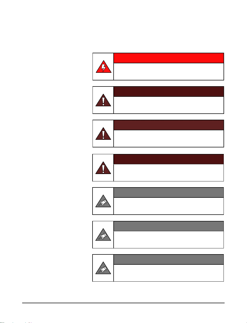
Review the safety guidelines provided below.
DANGER!
HAZARDOUS VOLTAGES
Exercise caution when installing and adjusting.
WARNING!
DO NOT make connections to motor or drive with power applied!
WARNING!
DO NOT spin motors with power off.
Volta
es generated by the motor can damage drives!
WARNING!
DO NOT switch operating modes with out using precautions.
Values set for one operatin
mode may not be proper for another!
1-8
Introduction
NOTE!
DO connect drives using good wiring and
workmanship practices.
NOTE!
DO operate drives within specifications
provided in this manual.
NOTE!
DO disconnect motors from loads while
settin
-up or servicing systems.

Chapter 2 Amplifier Connections
In general, use the Copley Motion ExplorerTM Kits'
Read Me First sheet for connection of the
amplifier to:
AC (or DC) power
A 3-phase brushless motor
Quadrature encoders
The control pendant or controller
PC or laptop (running Copley Motion
Explorer
Should you require it during installation, this chapter
provides specifics about amplifier connectors, including:
Ground
AC/DC Power and Motor Phase Connector (J1)
Motor Connector (J2)
Signal Connector (J3)
Data Connector (J4)
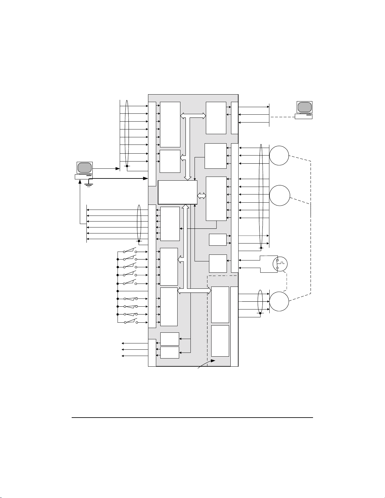
Figure 2-1 is a functional diagram of amplifier
connections.
At the end of this chapter, you'll find information
about the amplifier's signal module and Status
indicator.
TM
)
7XX8 Series Digital Servo Amplifier User Guide
2-1
Note:
Amplifier signal ground must be
connected to controller ground.
Buffered Enc A out
Buffered Enc /A out
Buffered Enc B out
Buffered Enc /B out
Buffered Enc X out
Buffered Enc /X out
Inputs
/Preset-0
/Preset-1
/Preset-2
/Preset-3
/Reset
Signal Gnd
/Enable
/Pos enable
/Neg enable
/Home
Outputs
Analog monitor
Status-0
Status-1
Ch. A
Ch. /A
Ch. B
Ch. /B
Ch. X
Ch. /X
Ref(+)
Ref(-)
Signal ground
Shld
Signal Gnd
Shld
J3
17
35
18
36
19
37
2
20
1
11
J3
12
30
13
31
14
32
1
5
24
6
25
23
26
3
21
22
4
J3
9
7
8
34
Pulse and
Direction
Format
Logic
Mode Selects
Dif Amp
&
ADC
Mode Selects
DSP
&
FLASH RAM
Encoder
buffer
Group Prog.
Pull-up/down
Preset
input
logic
Active
state Prog.
Group Prog.
Pull-up/down
Enable
input
logic
Active state
Prog.
Monitor
DAC
Status
FETS
RS-232
OR
RS-485
Driver/
Receiver
Jumper Selects
Hall
Receiver
Encoder
Receiver
&
Home
pulse
logic
+5V
Power
Sensor
ADC
PWM
Stage
"H"
Bridge
Current
Sense
Internal
DC
supply
Inrush
limiter
Note: Circuits within dashed line are
HOT! (At mains potential)
J4
Tx
2
Rx
3
Gnd
5
RS-232
Data Port
J2
Hall U
2
3
4
8
15
7
14
6
13
11
12
1
9
12
Hall V
Hall W
Enc A
Enc /A
Enc B
Enc /B
Enc X
Enc /X
+5V
0V
Shld
/Motemp
Gnd
Halls
Encoder
Motor Overtemp
Switch
J1
U
6
V
7
W
8
&
&
Shld
9
1
See Figure 2-4 for
information regarding
2
3
Motor
shielding
Figure 2-1 Functional Diagram Amplifier Connectors
Amplifier Connections
2-2

GrGr
oundingounding
Gr
ounding
GrGr
oundingounding
A single-point star ground should be used with all
device grounds converging. Do not daisy-chain the
connections to ground. The ground connections should
be as short a distance as possible. The motor ground
should be connected directly to the amplifier.
Safety GroundingSafety Grounding
Safety Grounding
Safety GroundingSafety Grounding
For safety, it is important that amplifier frame
ground on J1 be connected to earth ground, typically
through the power cable.
Note: Frame ground on AC models is at J1-3. Frame
ground on DC models is at J1-1.
The connections on the power board, such as the motor
phase, are at line potential.
Signal GroundingSignal Grounding
Signal Grounding
Signal GroundingSignal Grounding
The signal board is fully isolated from the power section
in this series of amplifiers. For proper operation,
connect the signal ground on J3 to the controller
ground.
Chassis & Cable Shield Grounding for EMIChassis & Cable Shield Grounding for EMI
Chassis & Cable Shield Grounding for EMI
Chassis & Cable Shield Grounding for EMIChassis & Cable Shield Grounding for EMI
Reduction & CEReduction & CE
Reduction & CE
Reduction & CEReduction & CE
To minimize noise radiation from the motor and power
cabling, wires should be twisted and shielded. Motor
sensor signals are often routed near the motor phase
winding cables. To minimize coupling of PWM noise,
sensor signal wiring should be multiple-conductorshielded cable. Further more, all cable shields should be
case grounded at both ends for compliance with CE
emissions limits. See Figure(s) 2-1 through 2-4 for
details.
7XX8 Series Digital Servo Amplifier User Guide
2-3

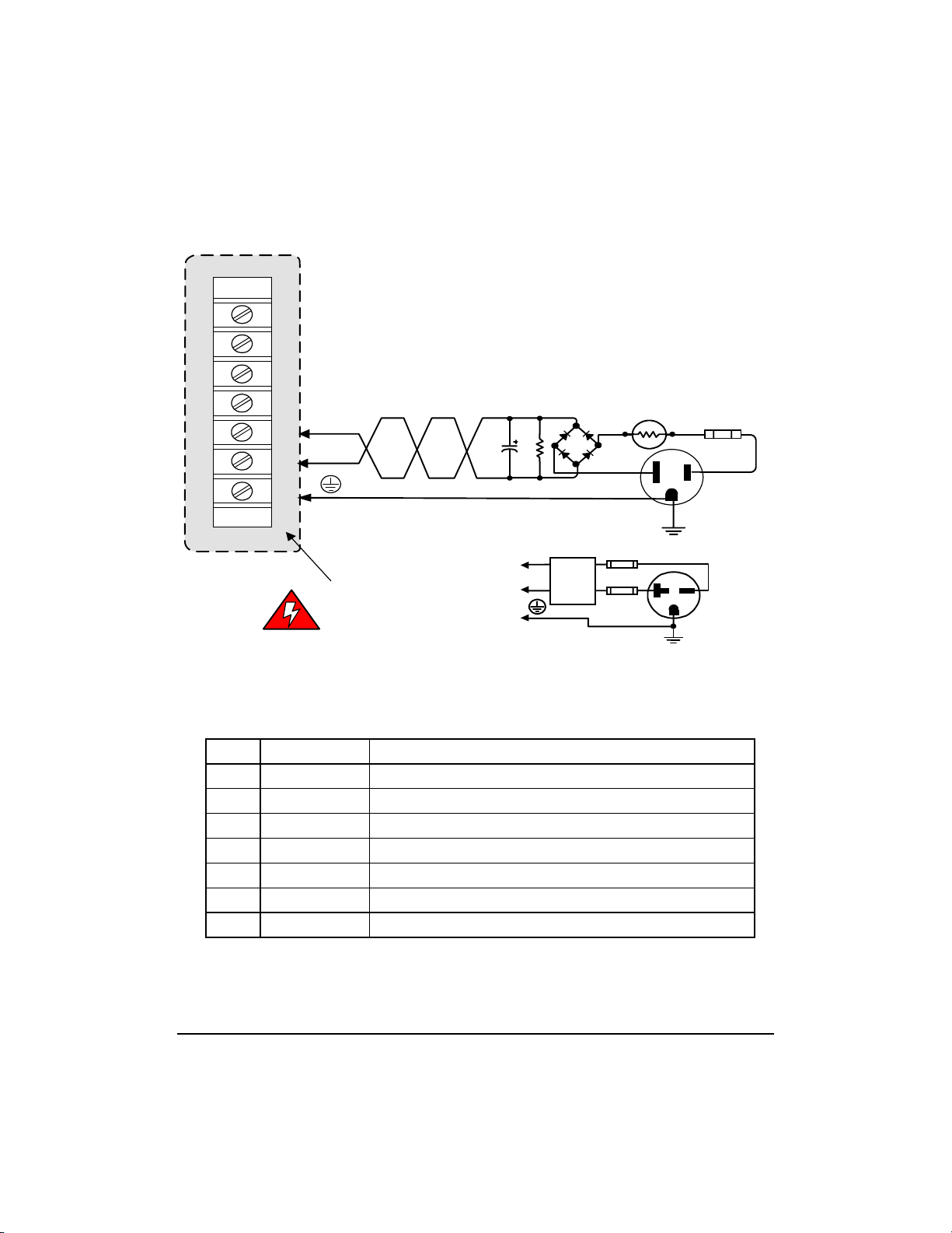
AC & DC Power & Motor Phase (J1)
Power supply and motor connections (Figure 2-2) should
be made with wire that has a rating to support the
amplifiers continuous current. AWG 14 wire supports all
amplifiers in this series. Additional recommendations: use
wire insulation with a voltage rating of 600V DC and a
temperature range of 105°C.
VV
oltaolta
gg
V
olta
VV
oltaolta
The mains for high voltage units that use 240V AC, 50/
60Hz, 1 phase, should be rated for a current of 20 amps.
The mains for low voltage units that use 120V AC, 50/
60Hz, 1 phase, should be rated for a current of 20 amps.
FusingFusing
Fusing
FusingFusing
Model 7228AC 7228DC 7428AC 7428DC
Fuse 120V@20A 120V@20A 250V@20A 230V@20A
Fusing should be time delayed and installed on any hot
lines coming from the mains. For low voltage units,
install the fuse on the hot line. For high voltage units,
install fuses on both hot lines.
e & Current Ratings of Mainse & Current Ratings of Mains
g
e & Current Ratings of Mains
gg
e & Current Ratings of Mainse & Current Ratings of Mains
Amplifier Connections
2-4
Line FilterLine Filter
Line Filter
Line FilterLine Filter
A line filter, such as the Corcom P/N20VDK6, must be
installed no more than three feet from the amplifiers
power entry terminal strip for compliance with CE
emissions limits.
s fs f
or EMI Reduction & CEor EMI Reduction & CE
s f
or EMI Reduction & CE
s fs f
or EMI Reduction & CEor EMI Reduction & CE
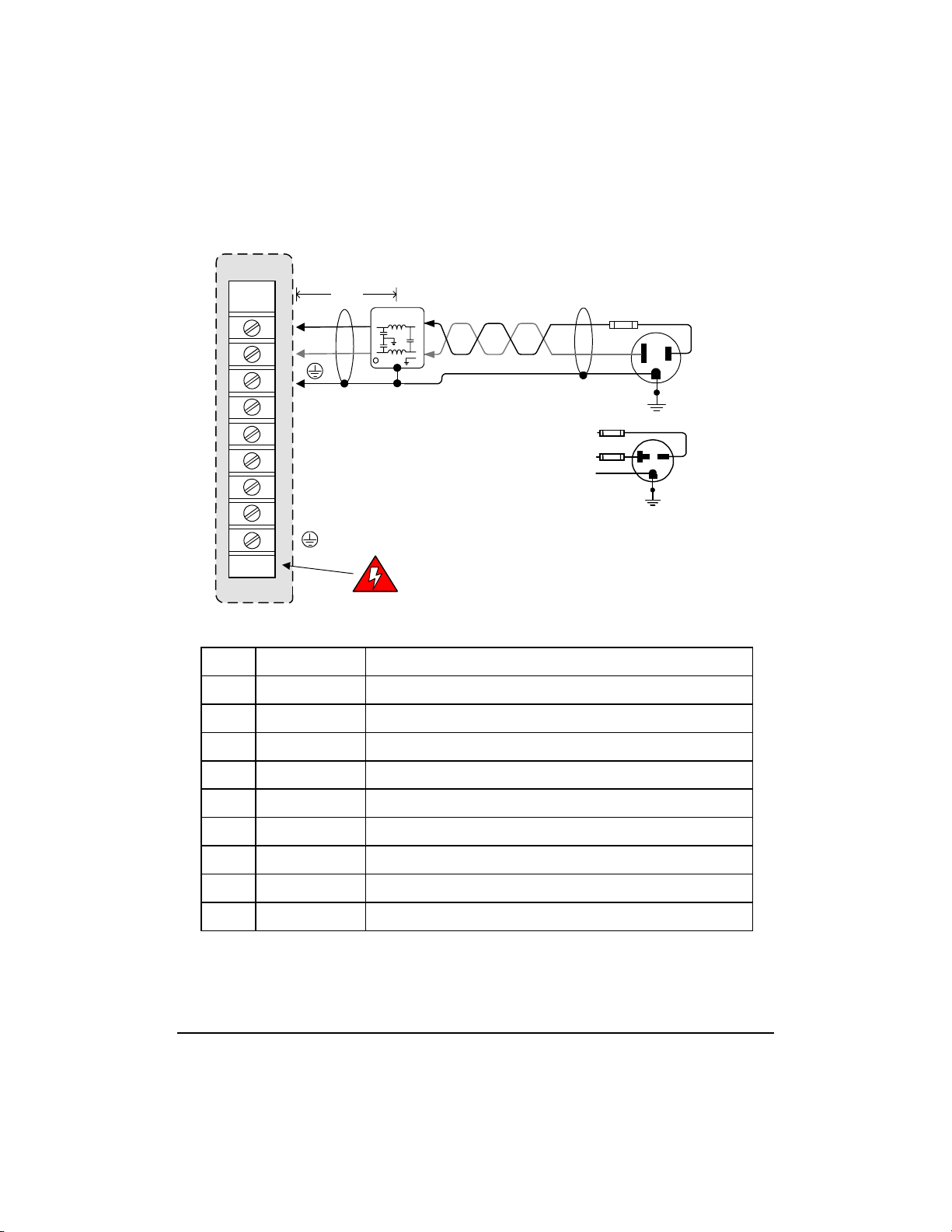
AC Model
J1
< 3ft
L1
1
L2
2
3
4
Buss +
5
Buss -
6
Motor U
7
Motor V
8
Motor W
9
Copley Amplifier
niPlangiSnoitcnuF
11L)sniamCAmorferiwnworbrokcalb(toHtupnIrewoPCA
Line Filter
c
Corcom
Note: All lines in this
power stage are HOT!
(At mains potential)
Figure 2-2 AC Model J1 Connector
Fuses: 20A
time-delay
Wht (Blu)
Grn (Grn/Yel)
Fuses: 20A
time-delay
Grn (Grn/Yel)
Blk (Brn)
120VAC
Blk (Brn)
230VAC
Wiring for 74XXAC
22L)sniamCAmorferiweulbroetihw(lartueNtupnIrewoPCA
3DNG)sniamCAmorferiwley/neergroneerg(dnuorgytefassissahC
4)+(ssuBylppusrewopCDlanretnifolanimretevitisoP
5)-(ssuBylppusrewopCDlanretnifolanimretevitageN
6UrotoMrotomfognidniwUottuptuoreifilpmA
7VrotoMrotomfognidniwVottuptuoreifilpmA
8WrotoMrotomfognidniwWottuptuoreifilpmA
9DNG.elbacrotomfodleihselbacrofoslA.dnuorgytefassissahC
Table 2-1 AC Model J1 Pin(s) Description
7XX8 Series Digital Servo Amplifier User Guide
2-5

DC Model PDC Model P
DC Model P
DC Model PDC Model P
No Transformer Required! This model operates from
power supplies that rectify the line directly with
full optical isolation between signal and power stages.
Voltage & Current Ratings of PowerVoltage & Current Ratings of Power
Voltage & Current Ratings of Power
Voltage & Current Ratings of PowerVoltage & Current Ratings of Power
SuppliesSupplies
Supplies
SuppliesSupplies
The power supply should deliver sufficient power P,
to supply the power delivered to the motor, and the
power lost in the amplifier.
In general, the supply voltage V should be larger
than the motors nominal voltage rating for the
absolute maximum voltage rating. Consult the motor
manufacturer for more information.
The current delivered by the supply can be calculated
from the equation I = P / V. Furthermore, the power
supply should be able to handle any current surge that
occurs during power up. The Copley amplifier limits
the current surge to 37 Amps maximum on power-up.
oo
wer Connectionswer Connections
o
wer Connections
oo
wer Connectionswer Connections
Amplifier Connections
2-6
External Capacitance RequiredExternal Capacitance Required
External Capacitance Required
External Capacitance RequiredExternal Capacitance Required
The capacitor used in the bridge rectifier circuit must be
able to keep the voltage ripple, or Vrip, at sufficient
levels and the capability of storing 10 times the energy
regenerated from the load. The capacitor C may be
calculated from this equation:
C = I / (120Hz * Vrip)
DC Model
J1
7
6
5
4
Buss -
3
Buss+
2
1
Copley Amplifier
Note: All lines in this
power stage are HOT!
(At mains potential)
Figure 2-3 DC Model J1 Connector
Note: Circuits shown are typical connections and are not
for design purposes.
niPlangiSnoitcnuF
1DNG)sniamCAmorferiwley/neergroneerg(dnuorgytefassissahC
2)+(ssuBylppusrewopCDmorflanimretevitisoptupnirewopCD
3)-(ssuBylppusrewopCDmorflanimretevitagentupnirewopCD
4UrotoMrotomfognidniwUottuptuoreifilpmA
5VrotoMrotomfognidniwVottuptuoreifilpmA
6WrotoMrotomfognidniwWottuptuoreifilpmA
7DNG.elbacrotomfodleihselbacrofoslA.dnuorgytefassissahC
Buss+
Buss-
DC
Power
Supply
Inrush limiter
Wht (Blu)
Grn (Grn/Yel)
Fuses
time-delay
Grn (Grn/Yel)
NTC
Fuses
time-delay
Blk (Brn)
120VAC
Wiring for 72XXDC
Blk (Brn)
230VAC
Wiring for 74XXDC
Table 2-2 DC Model J2 Pin(s) Description
7XX8 Series Digital Servo Amplifier User Guide
2-7
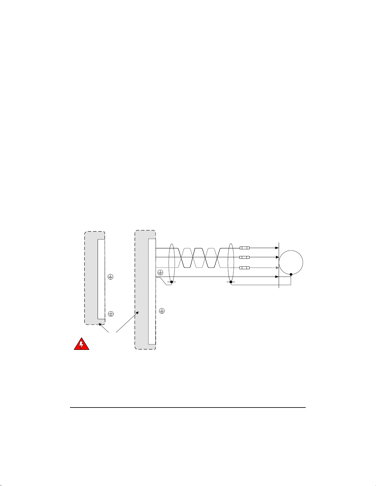
Motor Phase Wiring ConnectionsMotor Phase Wiring Connections
Motor Phase Wiring Connections
Motor Phase Wiring ConnectionsMotor Phase Wiring Connections
Motor Protection: Fusing & Circuit BreakersMotor Protection: Fusing & Circuit Breakers
Motor Protection: Fusing & Circuit Breakers
Motor Protection: Fusing & Circuit BreakersMotor Protection: Fusing & Circuit Breakers
To protect the motor, during the prototype phase, it is
the recommendation of Copley Controls Corp. to use
time delayed fusing in line with the motor. To protect
the motor from an unintentional event the current rating
should be no greater than the motors continuous stall
current.
ShieldingShielding
Shielding
ShieldingShielding
To minimize noise radiation from the motor cabling,
wires should be twisted and shielded. Furthermore, all
cable shields should be case grounded at both ends for
compliance with CE emissions limits.
DC Model
J1
4
5
6
7
2
Buss +
Buss -
3
1
Copley Driver
Note: All lines in this
power stage are HOT!
(At mains potential)
AC Model
J1
U
U
V
W
OR
6
V
7
W
8
9
Shield
L1
1
L2
2
3
Buss +
4
Buss -
5
Copley Driver
Figure 2-4 Motor Phase Wiring
Temporary Fuses
time-delayed
Phase U
Phase V
Phase W
Case Gnd
Motor
Note: Circuits shown are typical connections and are not
for design purposes.
Amplifier Connections
2-8

Motor Signal Connector (J2)Motor Signal Connector (J2)
Motor Signal Connector (J2)
Motor Signal Connector (J2)Motor Signal Connector (J2)
Connectors & CablingConnectors & Cabling
Connectors & Cabling
Connectors & CablingConnectors & Cabling
Motor signal connections should be made with wire that
has a rating to support the signal current. AWG 24 wire
will support all motor signals in this series. Additional
recommendations for wire insulation are for a voltage
rating of 300 V DC and a temperature range of 80°C. To
minimize coupling of PWM noise, encoder signal wiring
should be multiple-conductor twisted-pair shielded
cable. Furthermore, all cable shields should be case
grounded at both ends for compliance with CE
emissions limits.
niPlangiSnoitcnuF
1DNGytefaS.dnuorglangislanretniotdetcennoctoN.dnuorgsissahC
2UllaHUrofstupnillaHlatigiD
3VllaHVrofstupnillaHlatigiD
4WllaHWrofstupnillaHlatigiD
5devreseR
6X.hCcnEXlennahCredocnE
7B.hCcnEBlennahCredocnE
8A.hCcnEAlennahCredocnE
9pmetoMrosneserutarepetrotoM
01.C.NnoitcennocoN
11.Am052@V5+)1etoN(sllaHdnasredocnerofrewopCD
21.V0.sllaHdnaV5+rofdnuorglangiS
31X/.hCcnEX/lennahCredocnE
41B/.hCcnEB/lennahCredocnE
51A/.hCcnEA/lennahCredocnE
Table 2-3 J2 Hall and encoder Connections
Note 1: +5VDC @ 250mA also connects to J3-15, J3-27 and J2-11.
Combined not to exceed 250mA.
7XX8 Series Digital Servo Amplifier User Guide
2-9

15
J2
U
2
Hall
Receiver
Case Gnd
Encoder
Receiver
&
Home
pulse
logic
Case Gnd
8
+5V Power
250mA max.
J2
MOTOR
9
1
Sensor
ADC
Copley Driver
3
4
1
6
13
8
15
7
14
1
11
12
9
12
V
W
Enc X
Enc /X
Enc A
Enc /A
Enc B
Enc /B
+5V
0V
/Motemp
Gnd
Shld
Shld
Twisted Pair
Case Gnd
Encoder
Case Gnd
Motor Overtemp
Switch
Halls
Figure 2-5 J2 Signal Connector
Amplifier Connections
2-10
The J2 connector is a female Sub-D, 15 position with
#4-40 standoffs for the cable shell.
More About Encoder and Hall Sensor ConnectionsMore About Encoder and Hall Sensor Connections
More About Encoder and Hall Sensor Connections
More About Encoder and Hall Sensor ConnectionsMore About Encoder and Hall Sensor Connections
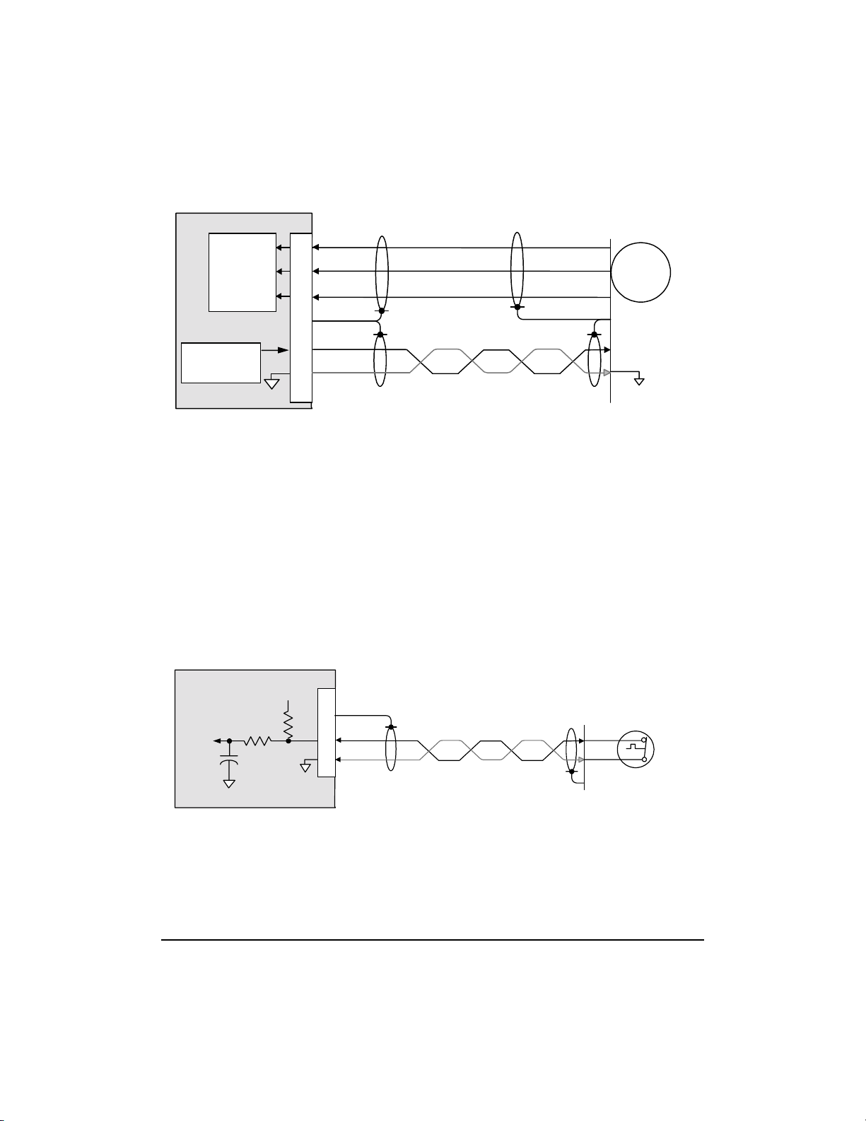
Encoder SensorEncoder Sensor
Encoder Sensor
Encoder SensorEncoder Sensor
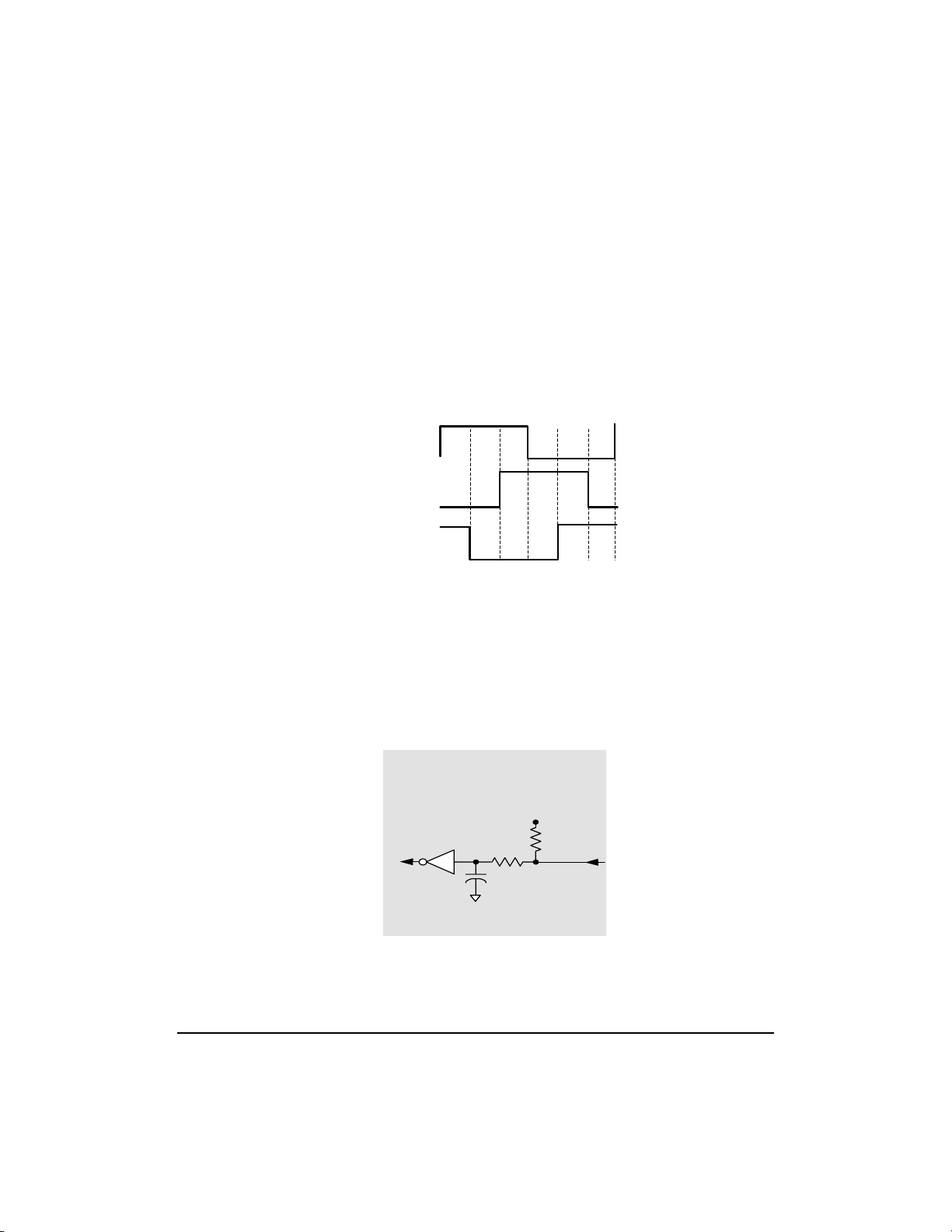
Quadrature encoders typically provide three signals
(Figure 2-6): two square waves (phase A and B) that
are 90° apart, and an index pulse, which will typically
occur once per revolution.

There are several ways to configure the encoder
interface. However, differential signals are
recommended for their inherently large CMRR (common
mode noise rejection ratio). For more information about
encoder formats see Chapter 3.
Index
Phase A
Phase B
Figure 2-6 Quadrature Encoder Pulses
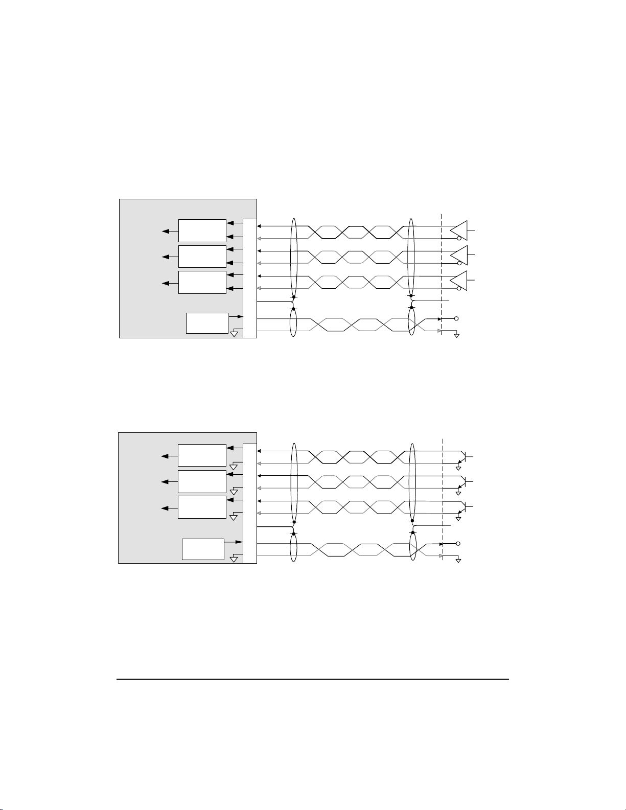
Encoder ReceiverEncoder Receiver
Encoder Receiver
Encoder ReceiverEncoder Receiver
The same encoder receiver circuit (Figure 2-7) is used
to receive the quadrature encoder pulses: phase A,
phase B, and index. This circuit is designed to work with
differential signals (Figure 2-8), single-ended TTL
signals and open collector circuits (Figure 2-9).
Receiver circuit
same for all encoder inputs
+5V
47pF
26LS32
A,B,X
1k
2.2k
/A, /B, /X
47pF
Figure 2-7 Encoder Receiver Circuirt
7XX8 Series Digital Servo Amplifier User Guide
1k
Copley Driver
2-11
Receiver circuit
same for all encoder inputs
Enc X
Enc A
Enc B
Copley Amplifier
J2
Index
Receiver
Phase A
Receiver
Phase B
Receiver
+5V Power
250mA max.
6
13
8
15
7
14
1
11
12
Enc X
Enc /X
Enc A
Enc /A
Enc B
Enc /B
Case Gnd
+5V
0V
Shld
Index
/Index
Phase A
Phase /A
Phase B
Phase /B
Figure 2-8 Quadrature Encoder, Differential Configuration
+5V
Gnd
Motor
Case Gnd
Index
Phase A
Phase B
Encoder
circuit power
Receiver circuit same for all encoder inputs
Enc X
Enc A
Enc B
Copley Amplifier
Index
Receiver
Phase A
Receiver
Phase B
Receiver
+5V Power
250mA max.
Figure 2-9 Quadrature Encoder, Single-ended Open Collector
Amplifier Connections
2-12
J2
6
12
8
12
7
12
1
11
12
Enc X
Enc A
Enc B
Case Gnd
+5V
0V
Shld
Index
Phase A
Phase B
+5V
Gnd
Motor
Case Gnd
Encoder
circuit power
Index
Phase A
Phase B
Hall SensorsHall Sensors
Hall Sensors
Hall SensorsHall Sensors
The controller performs a phase initialization routine,
using the encoder for proper commutation. However,
improved phase initialization can be achieved using Hall
sensors to determine initial positioning. Typical Hall
signals are shown in Figure 2-10.
One Electrical Cycle
Phase U
Phase V
Phase W
Typical 120 Degree Halls shown
Figure 2-10 Hall Signals
Hall Input CircuitHall Input Circuit
Hall Input Circuit
Hall Input CircuitHall Input Circuit
All 6 states
The same Hall input circuit (Figure 2-11) is used to
receive Hall signals: phase U, phase V, and phase W.
The circuit is designed to work with single-ended TTL
signals and single-ended open-collector signals.
Input circuit
same for all Hall signals
+5V
HCT14
10k
22k
10nF
Copley Amplifier
Figure 2-11 Hall Input Circuit
7XX8 Series Digital Servo Amplifier User Guide
2-13
Hall
Receiver
Case Gnd
+5V Power
250mA max.
Copley Amplifier
J2
11
12
Motor
U
2
V
3
W
4
1
Shld
+5V
Phase U
Phase V
Phase W
Halls
Case Gnd
Hall power
0V
Figure 2-12 Hall Connections
Temperature Sensor Input CircuitTemperature Sensor Input Circuit
Temperature Sensor Input Circuit
Temperature Sensor Input CircuitTemperature Sensor Input Circuit
The temperature sensor input circuit (Figure 2-13)
receives signals from sensing devices, such as thermal
sensors. The circuit works with resistive sensors, or an
open/closed switch to ground.
The 7XX8Series work well with N.O. (Normally Open),
N.C. (Normally Closed), or resistive sensors. The
overtemp threshold(s) are adjustable with CME and may
be stored as part of a preset.
Input circuit
Sensor signal
DSP
ADCN3
100nF
Copley Amplifier
Amplifier Connections
2-14
10k
+5V
5k
Figure 2-13 Temperature Sensor Input Circuit
J2
1
9
12
Case Gnd
/Motemp
Gnd
Motor
Motor Overtemp
Case Gnd
Switch
Normally
Closed

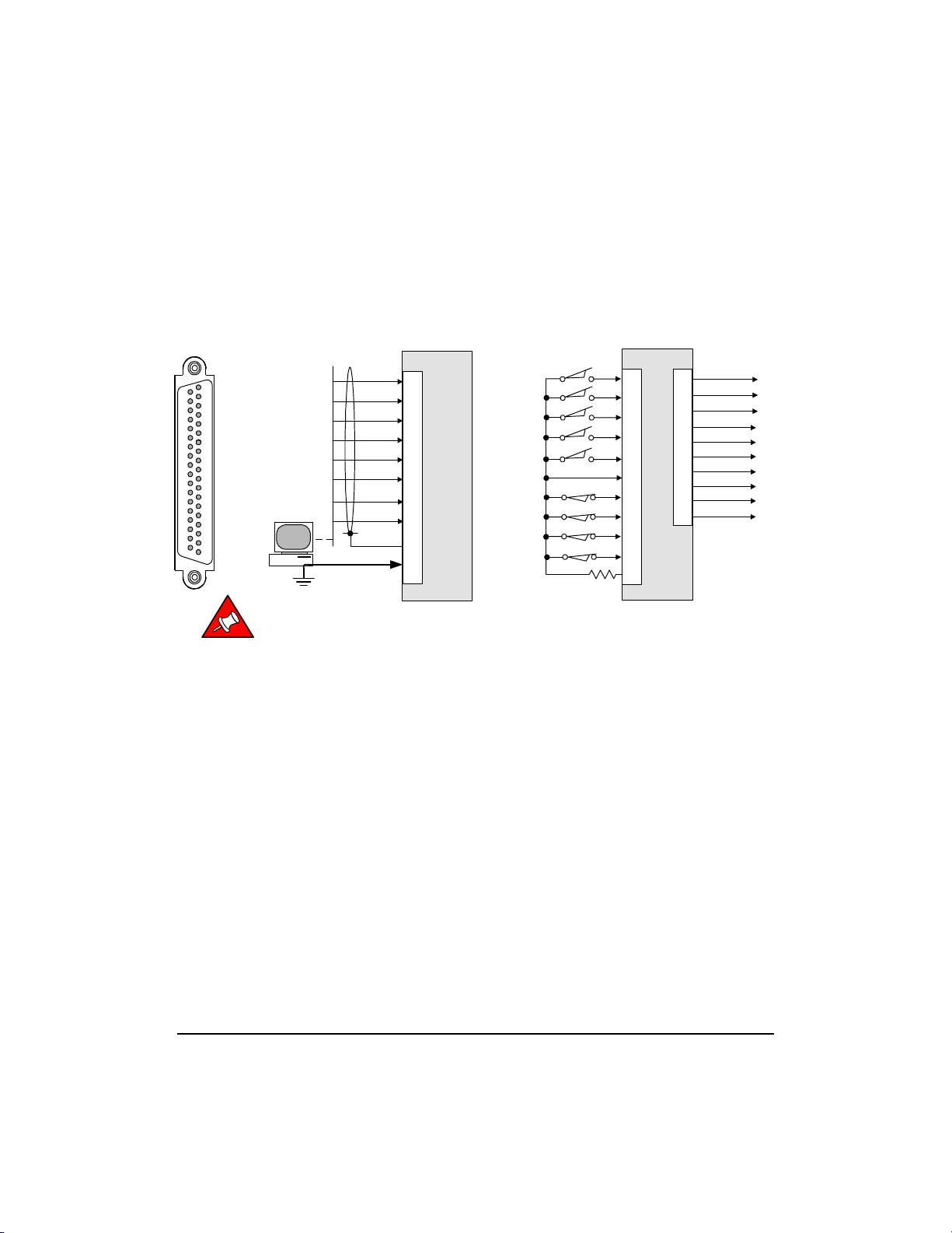
Signal Connector (J3)Signal Connector (J3)
Signal Connector (J3)
Signal Connector (J3)Signal Connector (J3)
Control signal connections should be made with wire
that has a rating to support the current signal. AWG 24
wire will support all motor signals in this series.
Additional recommendations are for a voltage rating of
300 V DC and a temperature range of 80° C. To
minimize coupling of PWM noise, sensor signal wiring
should be multiple-conductor twisted-pair shielded cable.
Further more, all shielded cables should be case
grounded at both ends for compliance with CE
emissions limits.
niPlangiSnoitcnuFniPlangiSnoitcnuF
1DNGytefaS.dnuorgemarf/sissahC
2)+(feRtupnidnammocgolanaV01-/+02)-(feRtupnidnammocgolanaV01-/+
3*tupnielbanE/elbanereifilpmA12*elbanEsoP/elbanenoitceridevitisoP
4*emoH/tupnihctiwsemoH22*elbanEgeN/elbanenoitceridevitageN
5*0-teserP/seniltcelesedomteserp4fo132*teseR/tupnitesertluafreifilpmA
6*2-teserP/seniltcelesedomteserp4fo142*1-teserP/seniltcelesedomteserp4fo1
7tuO0-sutatS1#tuptuosutatsreifilpmA52*3-teserP/seniltcelesedomteserp4fo1
8tuO1-sutatS2#tuptuosutatsreifilpmA62dngSV0dnuorGlangiS
9noMgolanAtuptuorotinomelbammargorP72tuptuOV5+tuptuoAm052@CDV5+
01timiLrruCtupnitimil-tnerruclanretxE82tuptuOV21+tuptuoAm52@CDV21+
11dngSV0dnuorGlangiS92tuptuOV21-tuptuoAm52@CDV21-
21tuoA.hCAhCtuptuoredocnedereffuB03tuoA/.hCA/hCtuptuoredocnedereffuB
31tuoB.hCBhCtuptuoredocnedereffuB13tuoB/.hCB/hCtuptuoredocnedereffuB
41tuoX.hCXhCtuptuoredocnedereffuB23tuoX/.hCX/hCtuptuoredocnedereffuB
51tuptuOV5+Am052@CDV5+33A.hCA.nahCtupniredocnE
61.C.NnoitcennocoN43.dnGgiSV0dnuorGlangiS
71niA.hCA.nahCtupniredocnE53niA/.hCA/.nahCtupniredocnE
81niB.hCB.nahCtupniredocnE63niB/.hCB/.nahCtupniredocnE
91niX.hCX.nahCtupniredocnE73niX/.hCX/.nahCtupniredocnE
Table 2-4 Signal Connections J3
Note: +5VDC @ 250 mA connects to J3-15, J3-27 and
J2-11. Combined current from all pins must not
exceed 250mA.
7XX8 Series Digital Servo Amplifier User Guide
2-15
* Pull-up to +5V, or pull-down to GND are selectable
and may be stored in a preset. In addition, the active
level (Hi or Lo) may also be selected and store as a
preset.
Outputs
A mon
Status-0
Status-1
Ch A out
Ch /A out
Ch B out
Ch /B out
Ch X out
Ch /X out
Signal Gnd
/Preset-0
/Preset-1
/Preset-2
/Preset-3
/Reset
Signal Gnd
/Enable
/Home
Curr Limit
Inputs
J3
5
24
6
25
23
26
3
21
22
4
10
Copley Driver
J3
9
7
8
12
30
13
31
14
32
34
3
7
19
Command Inputs
J3
SIGNAL
2
0
1
Note:
Amplifier signal ground must be
connected to controller ground.
Signal ground
Ch. A
Ch. /A
Ch. B
Ch. /B
Ch. X
Ch. /X
Ref(+)
Ref(-)
Shld
J3
17
35
18
36
19
37
2
20
1
11
Copley Driver
/Pos enable
/Neg enable
Figure 2-15 J3 Connector and Cabling
The J3 connector is a female Sub-D, 37-position with
#4-40 standoffs for cable shells.
Amplifier Connections
2-16
 Loading...