

1
COPLAND
DAC215
USER GUIDE

2
GETTING STARTED
Installation
Open the carton and remove the amplifier from its plastic bag. The AC-power cord is placed
in the bottom of the carton. Before placing the unit in your home, read this carefully.
CAUTION !
Various regulation agencies require us to bring the following information to your attention.
Please read carefully.
! Before plugging into the AC wall outlet, ensure that the tubes are well seated. The tubes can
be seen right behind the front panel grill. If necessary, the small grill plate right over the tubes
can be removed, hereby gaining access to push down the tubes until seated.
! Check that your supply voltage is the same as indicated on the back of the unit.
! To prevent fire or shock hazard, do not expose this unit to rain or moisture.
! Dangerous voltage inside. Do not open the cabinet while connected to the AC wall outlet.
There are no serviceable parts inside. Repairs should be carried out by qualified service
personnel only.
! Ensure that no objects or fluids pass through the ventilation openings.
If liquid is spilled into the amplifier, disconnect from the mains and consult a qualified service
technician.
Do not subject the unit to high mechanical vibration; the valves are sensitive to this.
The trouble-free life of an electronic instrument is greatly extended by providing sufficient
ventilation to prevent the build-up of high internal temperatures that cause deterioration.
Allow enough clearance so that cool air can enter at the front and top.
Input / Outputs
Use shielded cables to connect the signal source to the inputs. To minimise the possibility to
hum, the shielded cables should run parallel to each other or loosely twisted together. Locate
the cables away from speaker leads and AC power cords.
AC Power
The amplifier AC power cord is plugged into a 50/60 Hz wall outlet. The right voltage is
indicated on the back panel just beside to the AC power inlet.
All DAC215 are shipped with factory set mains working voltage according to the destination
country
The main voltage setting can only be changed by a qualified technician.
3
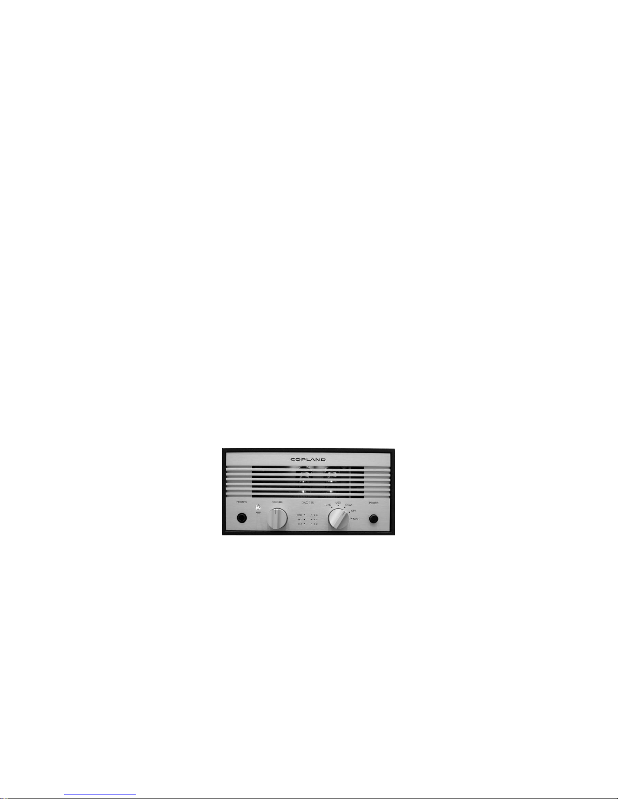
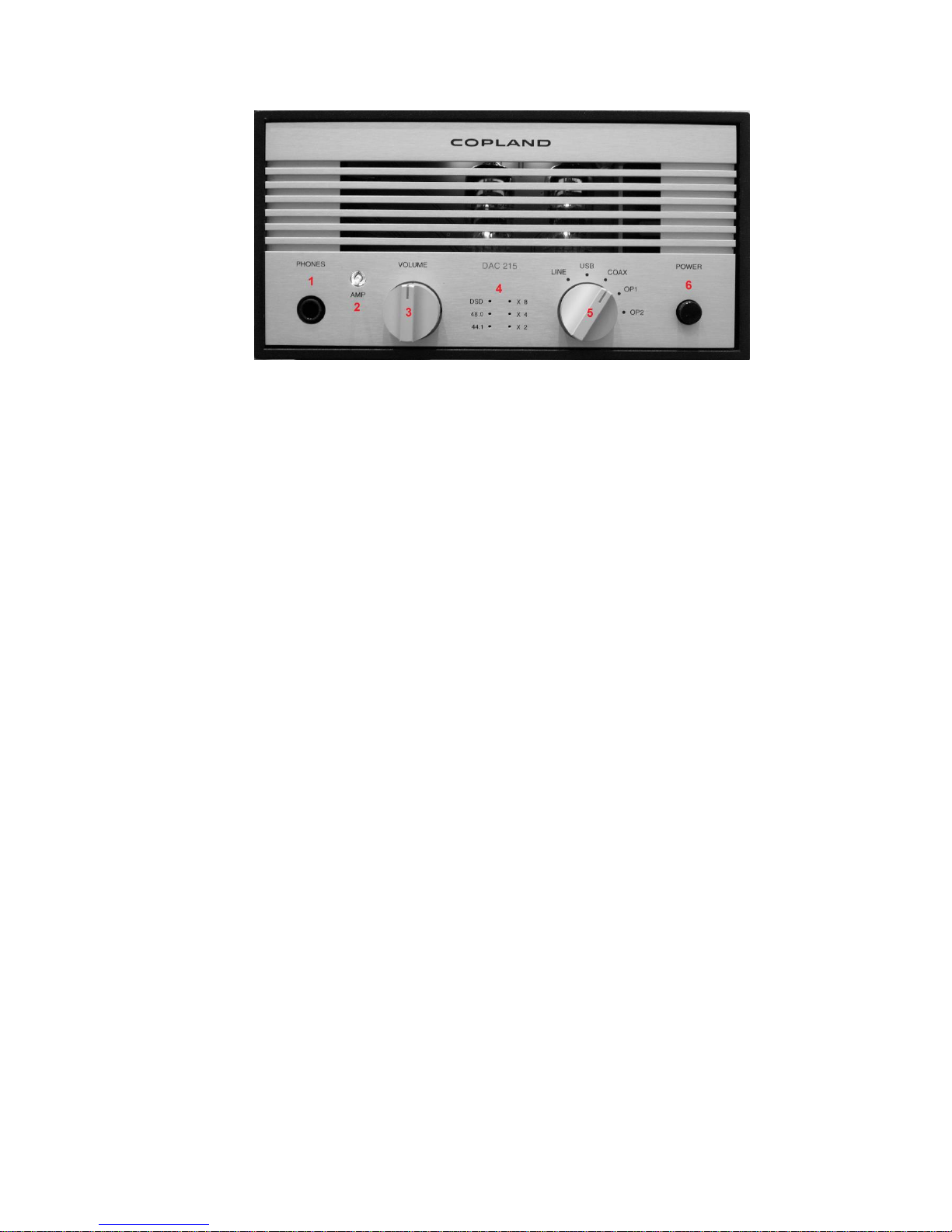
Front Panel
1. Headphone output: A Stereo 6.3mm (1/4”) jack for connecting the headphones.
Connecting headphones mutes the audio output from the back panel AMPLIFIER OUTPUT terminals.
2. Amplifier switch: The AMP switch is illuminated when the appliance is supplied with the
mains voltage and turned on by the power switch (6).
In off position, the switch light is red, the amplifier section of the unit is bypassed, and the
DAC output is directed straight to the back panel DAC output terminals.
In on position the switch light will turn green and the amplifier section is engaged. All incoming
signals will be directed through the amplifier to the back panel AMP output terminals or
straight to the front panel headphone output when a headphone is plugged in.
3. Audio level: To adjust the volume to the desired listening level. Turn the control clockwise
to increase the volume.
4. Sample rate: The incoming signal sample basis rate (44.1 kHz / 48 kHz or DSD single
rate) is shown at the right column LEDs.
Higher value sample rates are shown as the basis sample rate and a corresponding
multiplication factor shown at the right column LEDs.
44.1 kHz = 44.1 LED
48 kHz = 48 LED
88.2 kHz = 44.1 LED and x 2 LED
96 kHz = 48 LED and x 2 LED
176.4 kHz = 44.1 LED and x 4 LED
192 kHz = 48 LED and x 4 LED
352.8 kHz = 44.1 LED and x 8 LED
384 kHz = 48 LED and x 8 LED
DSD 64 = DSD LED
DSD128 = DSD LED and x 2 LED
DSD256 = DSD LED and x 4 LED
5. Source selector: Selects the appropriate input signal source.
6. Power switch: Pressing this button, the amplifier will switch cyclically between power on
and power off mode. Power on will be indicated by the light of the AMP switch (2).
The amplifier starts to play after 40 seconds. During the warmup period, the light of the AMP
switch (2) will be flashing.
4
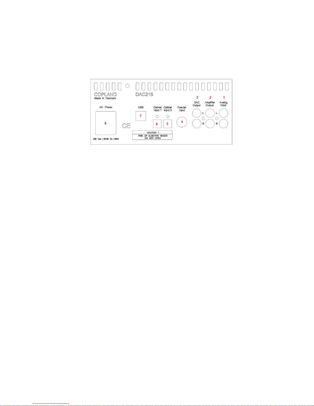
Back Panel
1. Analog input: Accepts a analog signal for instance from a tuner or a CD-Player
2. Amplifier output: Output from the volume control and amplifier section of DAC215.
Connect to the input of a power amplifier.
3. DAC output: Direct output from the DAC. Connect to a suitable input of an amplifier.
4. Coaxial input: S/PDIF (Sony/Philips Data Interface) input from a CD player.
It is a single ended square wave of amplitude around 0.5 V pp.
5. Optical input 2: TOSLINK - fiber optic transmission of S/PDIF.
6. Optical input 1: TOSLINK - fiber optic transmission of S/PDIF.
7. USB Input: Use a certified USB2.0 cable. Connect the cable to the DAC215 and then to
the external USB source.
8. AC power: The AC Power Cord is plugged here.
 Loading...