

■
Specifications are subject to change without notice. Specifications in this catalog are for reference. The formal specification sheets will be submitted upon request.
COPAL ELECTRONIC
S
Oct,
2005
■ MODEL NUMBER DESIGNATION
P S 6 0 - 1 0 2 R - N M C N
Series name Signal / power cable pullout method
Pressure port
Switch output interface
Rated pressure range
Pressure reference
102 : −100 ~ 100 kPa 103 : −100 ~ 1000 kPa
302 : −100 ~ 300 kPa
R : Compound pressure (Negative pressure ~ Positive pressure)
CN : Connector pullout
M : M5 female screw
N : NPN open collector
P : PNP open collector
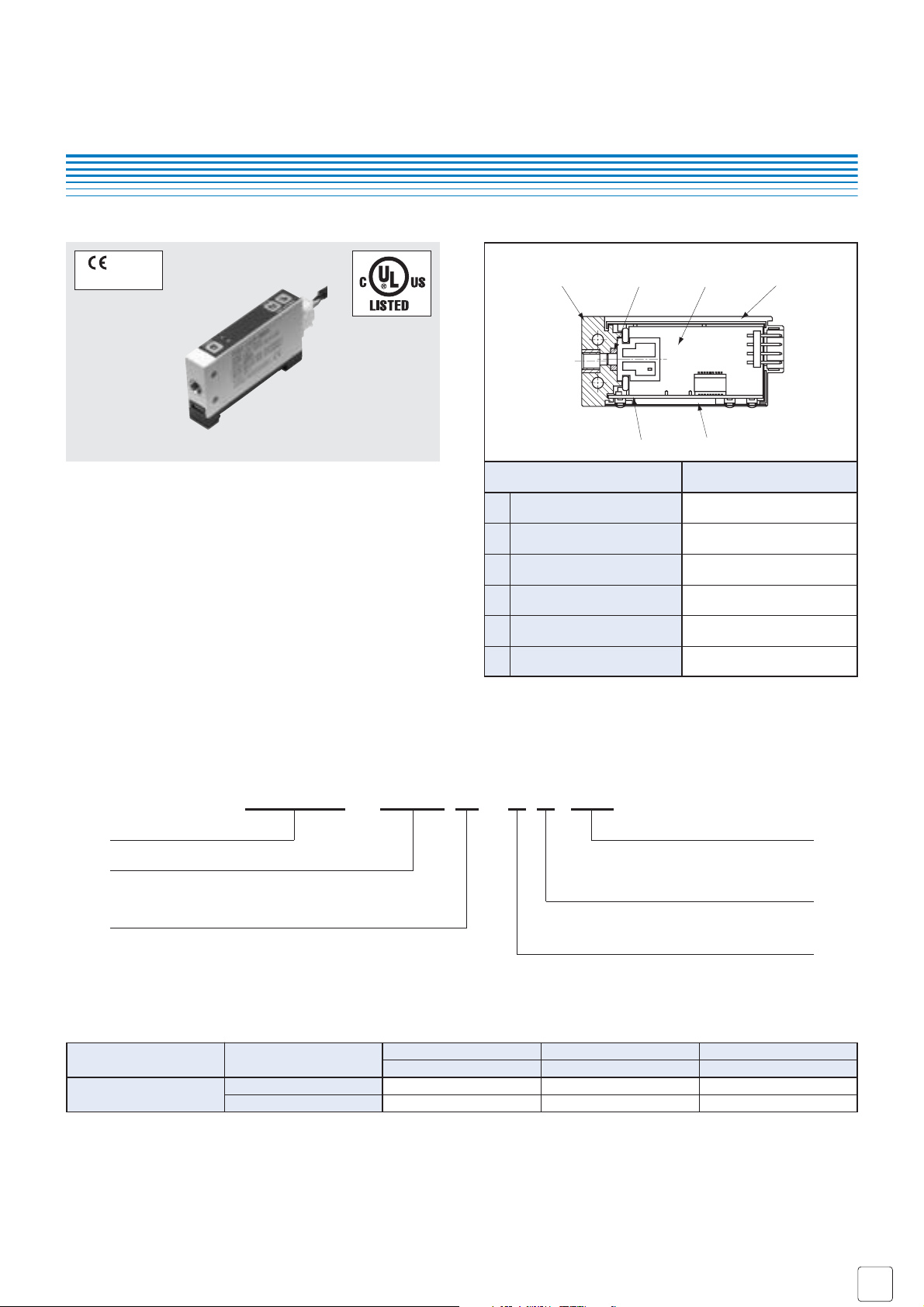
PRESSURE SWITCHES WITH GAUGE
PS60
1
2
3
4
5
6
Part name Material
Pressure port
“O” ring
Sensor module board
Housing
Display board
Operation panel seet
1
5
Polyamide (Resin of MXD6 series)
Brass (Ni-plated)
Fluoro-rubber
———
PBT (
Polybutyleneterephtalate)
———
Polyester
INTERNAL STRUCTURE
● Applicable for negative through positive pressure with 10
mm thick slim housing
●
Suitable for use in clean rooms with easy-to-use push keys
● Plug-in connector is provided for easy installation and
maintenance
● Space saving and mountable on DIN rails
● Data protection by panel lock system
● Low consumption by nondisplay mode
■ FEATURES
■ LIST OF MODEL NUMBERS
Pressure port
M 5 female screw
NPN open collector output
PNP open collector output
Switch output
102R 302R 103R
−100 ~ 100 kPa −100 ~ 300 kPa −100 ~ 1000 kPa
PS60-102R-NMCN PS60-302R-NMCN PS60-103R-NMCN
PS60-102R-PMCN PS60-302R-PMCN PS60-103R-PMCN
❈ Verify the above model numbers when placing orders.
marking
Compatible with
EMC directive
2
3
6
4
■
Specifications are subject to change without notice. Specifications in this catalog are for reference. The formal specification sheets will be submitted upon request.
COPAL ELECTRONIC
S
Oct,
2005
PS60
PRESSURE SWITCHES WITH GAUGE
General specifications
Display Power
Item Model number
102R 302R 103R
PS60
■ STANDARD SPECIFICATIONS
Pressure reference
Gauge
Non-corrosive gases
−100 ~ 100 −100 ~ 300 −100 ~ 1000
200 600 1500
500 1000 2000
−10 ~ 50
0 ~ 50
35 ~ 85 (No condensation)
−20 ~ 70 (Atmospheric pressure, humidity 65 %RH maximum)
Approx. 50 (Includihg cable)
12 ~ 24 V ± 10 % (Including ripple percentage)
30
100 (500 V DC)
± 3 %F.S. (0 ~ 50 °C)
500 V AC, 60 s (Leakage current 1 mA maximum)
M5 Female screw
3-digit LED
−100 ~ 100 kPa −100 ~ 300 kPa −0.10 ~ 1.00 MPa
± 1 %F.S.
1 count
Pressure medium
Rated pressure range kPa
Maximum pressure kPa
Break-down pressure kPa
Operating temp. range °C
Compensated temp. range °C
Operating humidity %RH
Storage temp. °C
Net weight g
Supply voltage V DC
Consumption current mA max.
Insulation resistance MΩ min.
Thermal error
Dielectric strength
Pressure port
Display element
Rated display range
Display accuracy
0 ~ 50 °C (Reference temp. 25 °C)
Resolution
● Unless otherwise specified, the specs are defined at an ambient temperature of 25 ± 5 °C and excitation voltage of 24 V DC.
Switch output
0 ~ 30 counts
30 V 100 mA maximum
1.2 (NPN), 2.2 (PNP)
−110 kPa (approx.) ~ “999” counts
Red LED ON
± 0.3 %F.S. maximum
Approx. 5, 25, 250
PS60 cable, DIN rail adaptor
Adjustable range
Switching capacity
Residual voltage V maximum
Display
Repeatability
Switch
hysteresis
Response ms
Accessories
NPN or PNP open collector output
Adjustable by panel switch
2
No. of outputs
Output interface
Setting method

■
Specifications are subject to change without notice. Specifications in this catalog are for reference. The formal specification sheets will be submitted upon request.
COPAL ELECTRONIC
S
Oct,
2005
PS60
PRESSURE SWITCHES WITH GAUGE
■ CIRCUIT DIAGRAMS
● NPN open collector ● PNP open collector
■ SWITCH OUTPUT MODE
■ DISPLAY RANGE
Note 1. In the Separate Mode, setting 1 corresponds to SW1, and
Setting 2 corresponds to SW2.
Note 2. In the Window Comparator Mode, the minimum value for
SW1 and SW2 corresponds to Setting 1 and the maximum
value corresponds to Setting 2.
❈ : Atmospheric pressure
● Display range can be selected as the table.
Note) “–” on the table indicates that it is not selectable in relation to resolution and display lines.
❈ : In terms of setting display range, please verify the default mode.
■ ENVIRONMENTAL CHARACTERISTICS
Test item Test conditions Permissible change
Vibration 10 ~ 500 Hz, 1.5 mm maximum/98.1 m/s2, 3 directions for 2 hours each
490 m/s
2
, 3 directions for 3 times each
40 °C, 90 ~ 95 %RH, 240 hrs.
0 ~ Rated pressure, 10
6
cycles
EMI : EN55011 (Group 1, Class B) : 1998
EMS : EN61326-1 : 1997 / A1 : 1998, EN61000-6-2 : 1999
Pressure indication and switch operating point :
± 2 %F.S., maximum each after test
Pressure indication and switch operating point :
± 5 %F.S., maximum during test
Shock
Moisture resistance
Pressure cycling
EMC
Number
1 (kPa)
2 (MPa)
3
4
5
6
Rated pressure range
102R
–100 ~ 100 –100 ~ 300 —
——–0.10 ~ 1.00
–75 ~ 75 –75 ~ 225 —
–1.00 ~ 1.00 –1.00 ~ 3.00 –1.0 ~ 10.0
–14.5 ~ 14.5 –14.5 ~ 43.5 –14 ~ 145
29.5 ~ 0.0
※
29.5 ~ 0.0
※
—
302R 103R
1
2
動作LED Indicator
主回路
Main circuit
センサ
Sensor
LED
圧力表示 Pressure indication
圧力
Pressure
2
1
動作LED Indicator
センサ
Main circuit
Sensor
圧力表示 Pressure indication
主回路
LED
負荷
Load
S.Output1
負荷
Load
S.Output2
Power B
Common C
圧力
Pressure
Output
Mode
Operation
1
2
3
4
5
6
7
8
Pressure setting
(Operating point)
SW1 SW2
Separate
Windowcomparator
Separate
Windowcomparator
HI LO A B HI LO A B
Setting1
(Lowerlimit):Setting1
(Upperlimit):Setting2
Setting2
(Lowerlimit):Setting1
(Upperlimit):Setting2
Separate mode
(HI operation)
OFF
P1: SW1 P2: SW2 P1 P2
-Pr
H H
(LO operation)
ON
P1: SW1
-Pr Pr
P1≦P2 or P1≧P2 P1≦P2–2H
H:Switch hysteresis,
P1=Setting 1, P2=Setting 2
P2: SW2
HH
ON ON
OFF
Power B
S.Output1
S.Output2
負荷 負荷
Load Load
Common C
Window comparator mode
(A operation)
OFF
Pr -Pr Pr
OFF OFF
H
(B operation)
P1 P2
-Pr Pr
H
H
ON
H
ON

■
Specifications are subject to change without notice. Specifications in this catalog are for reference. The formal specification sheets will be submitted upon request.
COPAL ELECTRONIC
S
Oct,
2005
■ OUTLINE DIMENTIONS Unless otherwise specified, tolerance : ± 0.5 (Unit: mm)
PS60
PRESSURE SWITCHES WITH GAUGE
●
Pressure port M type
(NMCN, PMCN)
Terminal no.
4
3
2
1
Connection
SW output 1
SW output 2
Power (DC10.8 ~ 26.4 V)
Common
Pin no.
4
3
2
1
Wire color Connection
Black SW output 1
White SW output 2
Blown
Power B
Blue Common
■ Accessories
● DIN rail adapter
● Connector cable
Pressure port (PA MXD6)
4.6
Pressure port (BSBM, Ni-plated)
Insert screw : M5 depth 5
8
4
1
Panel seet (Polyester)
0
–0.2
10.2
4.5
0
–0.2
12
25
Heat shrink tube (Black)
2 – 3.1
Mounting hole
DIN rail adapter (accessory)
Length : 1500 ± 50
(52.5)
4.5
(7)
Housing (PBT)
φ
13.2
9
Part No. (Laser marking)
Connector : Pitch / 4 poles (□0.64)
Housing : Made in JST (XAP-04V-1)
70 ± 20
50 ± 10 (5)
< Terminal No. >
1.1
4
4
1
Housing : JST (XAP-04V-1)
Contact : JST (SXA-001T-P0.6L)
4-core shielded cable
AWG26 ULNo.2844
φ
( 4)
PS60
1.5
5
10
1.1
6.5
DIN rail (width 35)
adaptaion
3.7
Tolerated stroke 2 maximuum
54.2
DIN base : PBT
Slide (DIN stopper) : POM
 Loading...