

Page 1

■
Specifications are subject to change without notice. Specifications in this catalog are for reference. The formal specification sheets will be submitted upon request.
COPAL ELECTRONIC
S
Oct,
2005
■ MODEL NUMBER DESIGNATION
P S 6 - 1 0 2 V - N A R
Series name Pressure port
Output
Switch output interface
Rated pressure range
Pressure reference
102 : 100 kPa
103 : 1000 kPa
G : Gauge
V : Gauge (Vacuum)
Combination of Rated pressure and pressure reference:
Negative pressure -100 kPa···102 V, Positive pressure 100 kPa···102G, 1000 kPa···103G
R : R1/8 male screw with M5 female screw
M : M5 female screw
A : 1 SW output and adjustable hysteresis + Analog output
W : 2 SW outputs
N : NPN open collector
P : PNP open collector
PRESSURE SWITCHES WITH GAUGE
PS6
1
2
3
4
5
6
Part name Material
Pressure port
Housing
“O” ring
Sensor module board
Protection panel
Main panel
1
POM (Polyoxymethylene)
PC (Polycarbonate)
Fluoro-rubber
———
PET (Polyethyleneterephthalate)
INTERNAL STRUCTURE
●
Solidstate pressure switch with no mechanical moving parts
● 2 types of pressure ports are available
● Open collector output of either NPN or PNP is available
● Analog output type available
■ FEATURES
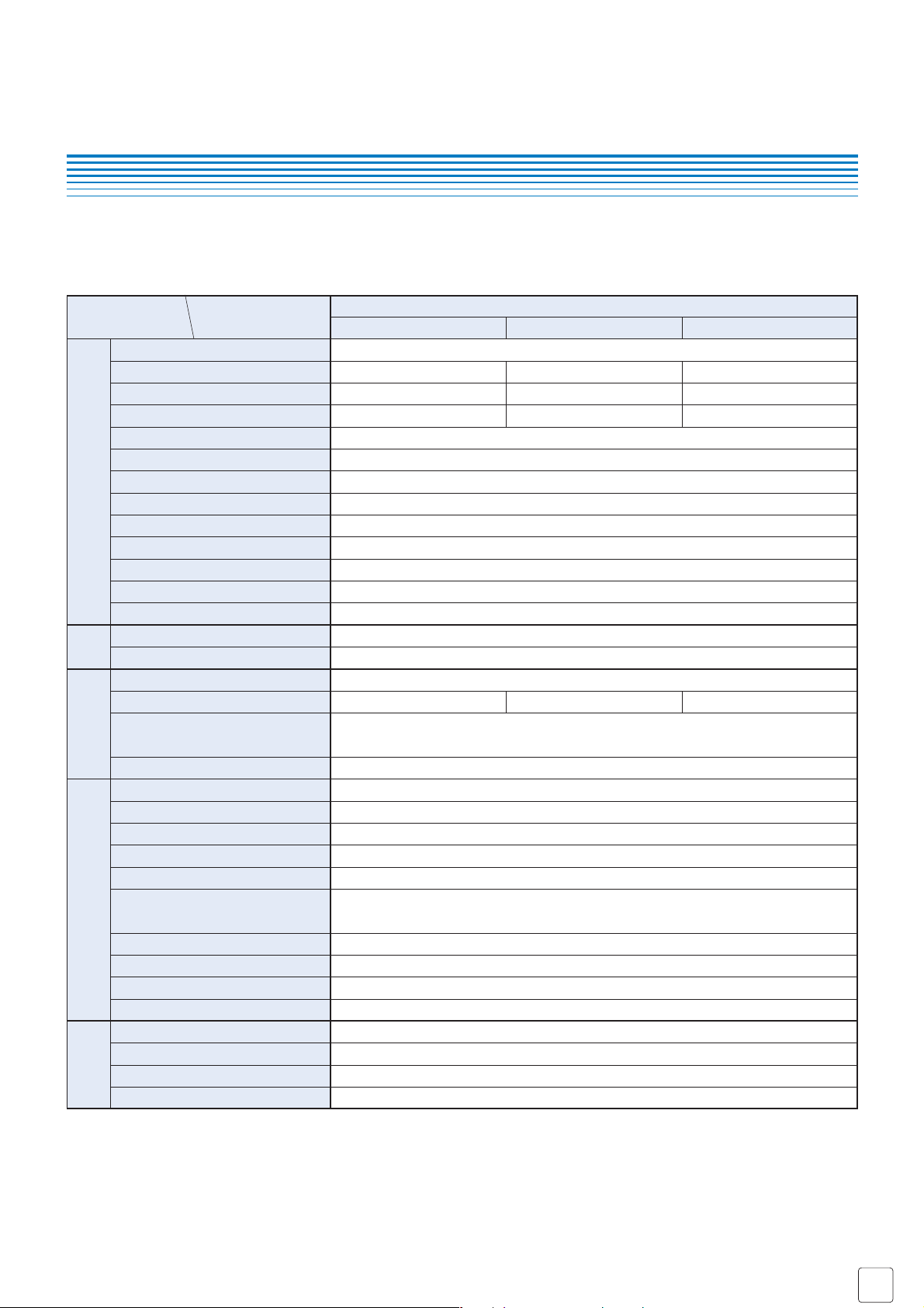
■ LIST OF MODEL NUMBERS
Pressure port
R 1/8 male
screw
M 5 female
screw
Outputs
Adjustable hysteresis switch output + Analog output
NPN open collector output
PNP open collector output
NPN open collector output
PNP open collector output
NPN open collector output
PNP open collector output
NPN open collector output
PNP open collector output
Switch outputs (2 points)
Adjustable hysteresis switch output + Analog output
Switch outputs (2 points)
Switch output
102V 102G 103G
0 ~ −100 kPa 0 ~ 100 kPa 0 ~ 1000 kPa
PS6-102V-NAR PS6-102G-NAR PS6-103G-NAR
PS6-102V-PAR PS6-102G-PAR PS6-103G-PAR
PS6-102V-NWR PS6-102G-NWR PS6-103G-NWR
PS6-102V-PWR PS6-102G-PWR PS6-103G-PWR
PS6-102V-NAM PS6-102G-NAM PS6-103G-NAM
PS6-102V-PAM PS6-102G-PAM PS6-103G-PAM
PS6-102V-NWM PS6-102G-NWM PS6-103G-NWM
PS6-102V-PWM PS6-102G-PWM PS6-103G-PWM
❈ : Verify the above model numbers when placing orders.
marking
Compatible with
EMC directive
Pressure
3
5
2
4
6
Page 2
■
Specifications are subject to change without notice. Specifications in this catalog are for reference. The formal specification sheets will be submitted upon request.
COPAL ELECTRONIC
S
Oct,
2005
PS6
PRESSURE SWITCHES WITH GAUGE
General specifications
Display
Power
Item Model number
PS6
102V 102G 103G
■ STANDARD SPECIFICATIONS
Pressure reference
Gauge
Non-corrosive gases
0 ~ −100 0 ~ 100 0 ~ 1000
200 200 1500
500 500 2000
−10 ~ 60
0 ~ 50
35 ~ 85 (No condensation)
−20 ~ 70 (Atmospheric pressure, humidity 65 %RH maximum)
Approx. 50 (Including cable)
12 ~ 24 V ± 10 % (Including ripple percentage)
35
100 (500 V DC)
500 V AC, 60 s (Leakage current 1 mA maximum)
R 1/8 (Female screw) or M5 female screw
2-digit LED
−0 ~ −99 kPa 0 ~ 99 kPa .0 ~ .99 MPa
± 3 %F.S.
1 count
Pressure medium
Rated pressure range kPa
Maximum pressure kPa
Break-down pressure kPa
Operating temp. range °C
Compensated temp. range °C
Operating humidity %RH
Storage temp. °C
Net weight g
Supply voltage V DC
Consumption current mA max.
Insulation resistance MΩ min.
Dielectric strength
Pressure port
Display element
Rated display range
Display accuracy
0 ~ 50 °C
(Reference temp. 25 °C)
Resolution
● Unless otherwise specified, the specs are defined at an ambient temperature of 25 ± 5 °C and excitation voltage of 12 V DC.
Switch output
Analog output
Approx. 0 ~ 15 % of the set value (W type only 2 % F.S. maximum)
30 V 80 mA maximum
0.8 (NPN), 1.2 (PNP)
0 ~ 100 of rated pressure
❈2
❈1
Red LED ON (W type only : SW1 Red, SW2 Green)
± 3
Approx. 2
1 ~ 5
1 ± 0.1
4 ± 0.1
1 (Load resistance 5 kΩ minmum)
Adjustable range
Switching capacity
Residual voltage V maximum
Display
Accuracy
0~ 50 °C %F.S
(Reference temp. 25 °C)
Switch
hysteresis
Response ms
Output voltage V
Zero voltage V
Span voltage V
Output current mA maximum
❈1 : Please set adjusting torque at 30 mN·m maximum.
❈2 : The actual setting range adjustable by VR has a little overrunning margin beyond the rated display of 0 through 99.
This could cause the setting value of VR may be under “0” or over “99”.
NPN or PNP open collector output
Adjustable by VR
1 or 2
No. of outputs
Output interface
Setting method
Page 3

■
Specifications are subject to change without notice. Specifications in this catalog are for reference. The formal specification sheets will be submitted upon request.
COPAL ELECTRONIC
S
Oct,
2005
●
NAN, NAR (NPN/Adjustable hysteresis switch)
● PS6-102V
● PS6-***G
●
PAN, PAR (PNP/Adjustable hysteresis switch)
PS6
PRESSURE SWITCHES WITH GAUGE
■ CIRCUIT DIAGRAMS
■ ENVIRONMENTAL CHARACTERISTICS
Test item Test conditions Permissible change
Vibration 10 ~ 500 Hz, 1.5 mm maximum/98.1 m/s2, 3 directions for 2 hours each
196 m/s
2
, 3 directions for 3 times each
40 °C, 90 ~ 95 %RH, 240 hrs.
0 ~ Rated pressure, 10
6
cycles
EN61326-1 (1997), -A1(1998)
Pressure indication, switch operating points and
analog output variation :
± 2 %F.S., maximum each after test
± 5 %F.S., maximum during test
Shock
Moisture resistance
Pressure cycling
EMC
■ SWITCHING OPERATION
● The switch turns on at the set pressure and turns off at the set pressure minus the hysteresis.
❈1 : *A* is adjustable hysteresis type.
● NWN, NWR (NPN/2 switch outputs) ● PWN, PWR (PNP/2 switch outputs)
1
Pressure
Sensor
Indicator
Main circuit
LED
Pressure indication
Load
S.Output1
FG
Power B
A.Output1
Common C
Indicator
1
2
Power B
Load
Pressure
Sensor
Main circuit
Load
S.Output1
FG
S.Output2
Common C
1
Indicator
Pressure
Pressure
1
Sensor
Sensor
2
Indicator
Main circuit
LED
Pressure indication
Main circuit
S.Output1
Load
S.Output2
FG
FG
S.Output1
LoadLoad
Power B
A.Output1
Common C
Power B
Common C
ON
OFF
Set value
Hysteresis
ON
OFF
Barometic
pressure
pressure
Hysteresis
Set value−100 kPa Rated pressureBarometic
Page 4

■
Specifications are subject to change without notice. Specifications in this catalog are for reference. The formal specification sheets will be submitted upon request.
COPAL ELECTRONIC
S
Oct,
2005
■ OUTLINE DIMENTIONS Unless otherwise specified, tolerance : ± 0.5 (Unit: mm)
PS6
PRESSURE SWITCHES WITH GAUGE
● Pressure port R type (NAR, PAR, NWR, PWR)
● Pressure port M type (NAM, PAM, NWM, PWM)
Wire color
Brown
Black
White
Blue
Shield
Connection
Power
B
Switch output
Analog output
Common
N.C.
PS6 (NAM,NAR, PAM, PAR)
Wire color
Brown
Black
White
Blue
Shield
Connection
Power
B
Switch output 1
Switch output 2
Common
N.C.
PS6 (NWM, NWR, PWM, PWR)
Switch status LED 1 (Red)
Switch status LED 2 (Green) ※Only for two-switch output model
POM
Polyoxymethylene
Display selector switch (ME/SW) ※For two-output switch (ME/S1/S2)
Recommended adjusting torque 25 mN·m maximum
φ
2 – 3.3
Mounting hole
4.5
52.5
Pressure port
M5 depth 5
R1/8
25
12
10
8.5
Switch status LED 1 (Red)
POM
Polyoxymethylene
Display selector switch (ME/SW) ❈ For two-output switch (ME/S1/S2)
Recommended adjusting torque 25 mN·m maximum
Switch status LED 2 (Green) ❈ Only for two-switch output model
Pressure indication
Pressure indication
Hysteresis setting VR ※Used to set the switch 2 for two-switch output model
Recommended adjusting torque 30 mN·m maximum
Pressure setting VR ※Used to set the switch 1 for two-output type
Recommended adjusting torque 30 mN·m maximum
Polycarbonate
4-core shielded cable
L = 1500 ± 50 AWG26
Hysteresis setting VR ❈ Used to set the switch 2 for two-switch output model
Recommended adjusting torque 30 mN·m maximum
φ
( 3.8)
ULNo.2844
Pressure port
M5 Depth 5
Pressure setting VR ❈ Used to set the switch 1 for two-switch output model
10
5
19
2 – M3
Depth 4.5
12
25
4.5
φ
2 – 3.3
Mounting hole
52.5
Recommended adjusting torque 30 mN·m maximum
4-core shielded cable
L = 1500 ± 50 AWG26
φ
( 3.8)
ULNo.2844
Polycarbonate
 Loading...