

■
Specifications are subject to change without notice. Specifications in this catalog are for reference. The formal specification sheets will be submitted upon request.
COPAL ELECTRONIC
S
Oct,
2005
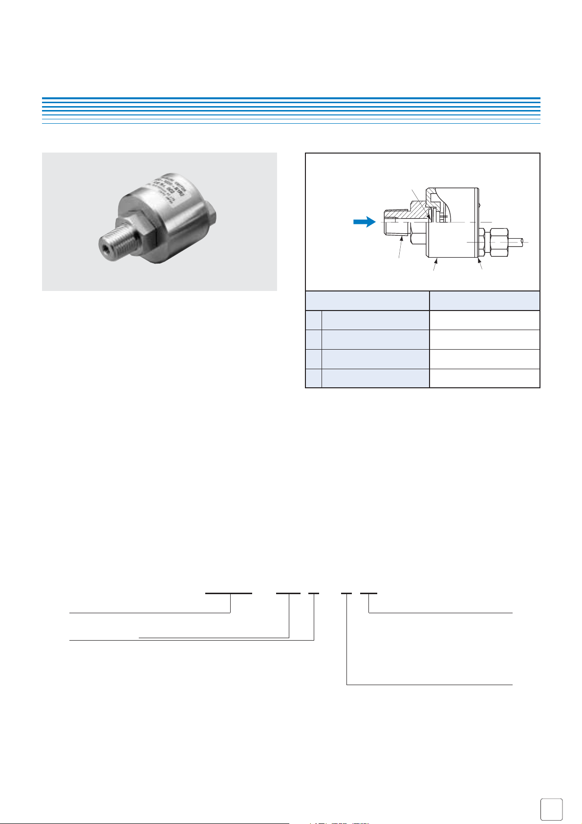
PRESSURE TRANSDUCERS WITH AMP.
PA-850
Part name Material
Plastic cover
Housing
Stainless steel diaphragm
Fitting
1
2
3
4
4
ABS (Acrylonitrile butadiene
styrene) + PC (Polycarbonate)
SUS 316L
SUS 316L
SUS 316L
INTERNAL STRUCTURE
PA-850
● High corrosion resistance and drip-proof construction
Pressure port attachment made of SUS 316L
Proven IP-65 grade gauge body (IP-65 in accordance with IEC)
● Standard product provides both a switch output
(hysteresis adjustable) and an analog output
● Absolute pressure type and compound pressure type
which can control negative to positive pressure with only
a single pressure gauge are all in line
● Three standard types of joint are provided
R2 : R 1/4 (M 5 female screw)
GF : G 3/8 with flash diaphragm
G2 : G 1/4 (M 5 female screw)
■ FEATURES
■ MODEL NUMBER DESIGNATION
PA-850 - 102 R - N R2
Series name
Pressure reference Rated pressure range
G : Gauge
V : Gauge (Vacuum)
R : Compound
A : Absolute
102 : 0 ~ 100 kPa
352 : 0 ~ 350 kPa
103 : 0 ~ 1000 kPa
102 : 0 ~ − 100 kPa
102 : − 100 ~ 100 kPa
302 : − 100 ~ 300 kPa
102 : 0 ~ 100 kPa abs
Fitting
R2 : R 1/4 with M 5 female screw
GF : G 3/8 with flash diaphragm
G2 : G 1/4 with M 5 female screw
Switch output interface
N : NPN open collector (Upper limit mode)
P : PNP open collector (Upper limit mode)
❈ Please refer to the LIST OF MODEL NUMBERS when placing orders.
Pressure
1
2
3
■
Specifications are subject to change without notice. Specifications in this catalog are for reference. The formal specification sheets will be submitted upon request.
COPAL ELECTRONIC
S
Oct,
2005
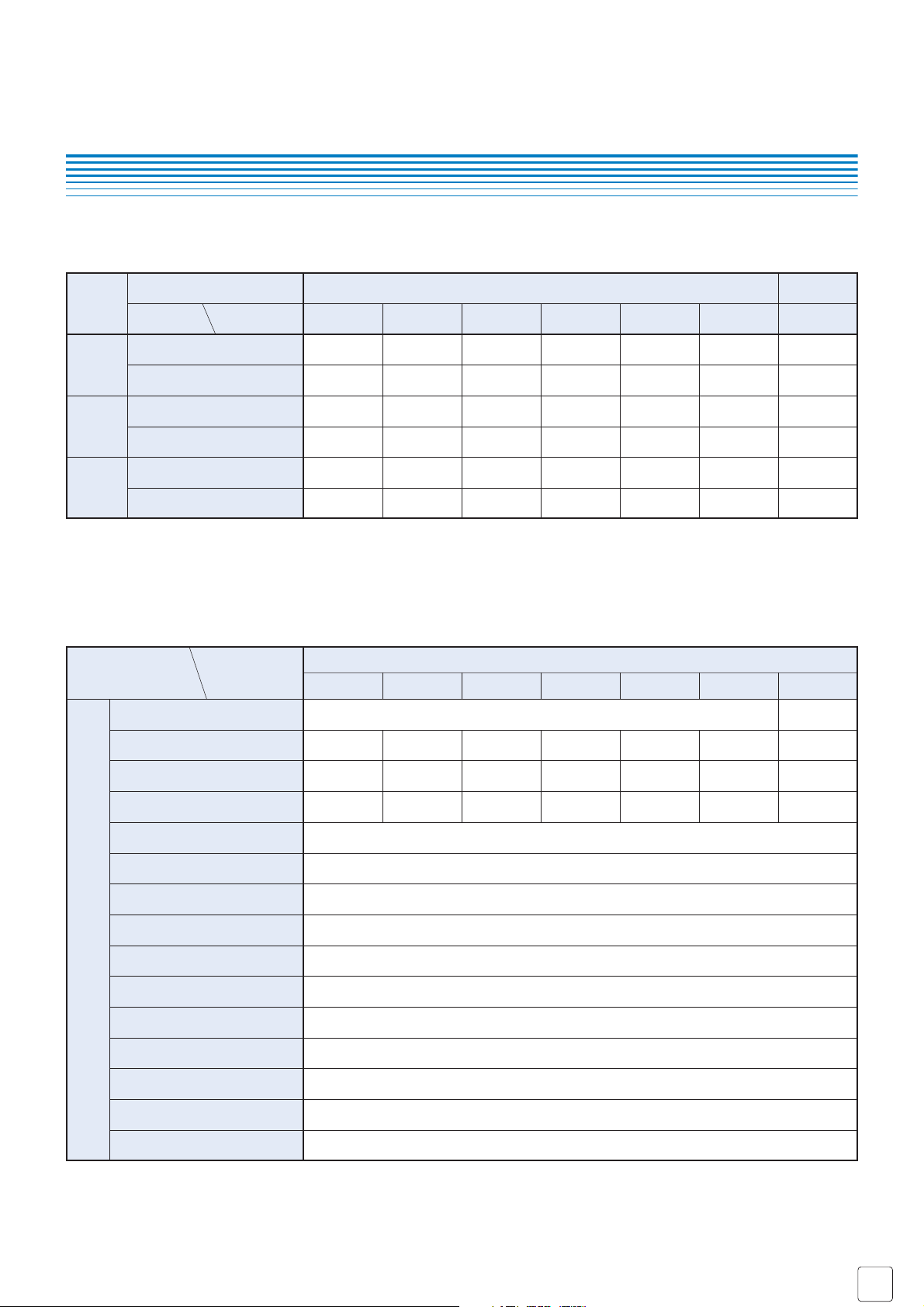
Pressure reference
Gauge Absolute
0 ~ 100 0 ~ 350 0 ~ 1000 0 ~ − 100 − 100 ~ 100 − 100 ~ 300 0 ~100
Rated pressure range
[
kPa]
Fitting
R2
(R 1/4)
GF
(G 3/8)
G2
(G 1/4)
NPN
PNP
NPN
PNP
NPN
PNP
■ LIST OF MODEL NUMBERS
PA-850-
102G-NR2
PA-850-
102G-PR2
PA-850-
352G-PR2
PA-850-
103G-PR2
PA-850-
102G-NGF
PA-850-
352G-NGF
PA-850-
103G-NGF
PA-850-
102V-NGF
PA-850-
102R-NGF
PA-850-
302R-NGF
PA-850-
102A-NGF
PA-850-
102G-PGF
PA-850-
352G-PGF
PA-850-
103G-PGF
PA-850-
102V-PGF
PA-850-
102R-PGF
PA-850-
302R-PGF
PA-850-
102A-PGF
PA-850-
102G-NG2
PA-850-
352G-NG2
PA-850-
103G-NG2
PA-850-
102V-NG2
PA-850-
102R-NG2
PA-850-
302R-NG2
PA-850-
102A-NG2
PA-850-
102G-PG2
PA-850-
352G-PG2
PA-850-
103G-PG2
PA-850-
102V-PG2
PA-850-
102R-PG2
PA-850-
302R-PG2
PA-850-
102A-PG2
PA-850-
102V-PR2
PA-850-
102R-PR2
PA-850-
302R-PR2
PA-850-
102A-PR2
PA-850-
352G-NR2
PA-850-
103G-NR2
PA-850-
102V-NR2
PA-850-
102R-NR2
PA-850-
302R-NR2
PA-850-
102A-NR2
SW output interface
Verify the above model numbers when placing orders.
PA-850
PRESSURE TRANSDUCERS WITH AMP.
General specifications
■ STANDARD SPECIFICATIONS
Item
Pressure reference
Rated pressure range
Maximum pressure
Break-down pressure
Operating temp. range
Compensated temp. range
Storage temp.
Operating humidity
Pressure medium
Insulation resistance
Dielectric strength
Sealed liquid
Pressure port
Net weight
Drip-proof structure
Model number
PA-850
102G 352G 103G 102V 102R 302R 102A
Gauge Absolute
100 350 1000 − 100 − 100 ~ 100 − 100 ~ 300 100 (abs)
200 700 2000 200 200 600 200 (abs)
300 1050 3000 300 300 900 300 (abs)
Corrosive gases/liquids compatible with SUS 316L
Approx. 180
IP-65
100 (500 V DC)
800 V AC, 60 s (Leakage current 1 mA maximum)
Silicone oil
R 1/4, G 3/8 (Flash diaphragm), G 1/4 ❈1
❈1 : An “O” ring provided. (G3/8 : P18, G1/4 : P15)
0 ~ 50
35 ~ 85 (No condensation)
−
20 ~ 80 (Atmospheric pressure, humidity 65 %RH maximum)
− 20 ~ 80
kPa
kPa
kPa
°C
°C
%RH
°C
MΩ
minimum
g
● Unless otherwise specified, the specs are defined at an ambient temperature of 25±5 °C and excitation voltage of 12 V DC.

■
Specifications are subject to change without notice. Specifications in this catalog are for reference. The formal specification sheets will be submitted upon request.
COPAL ELECTRONIC
S
Oct,
2005
PA-850
PRESSURE TRANSDUCERS WITH AMP.
Gravitational effect
(From horizontal position to vertical position)
No. of outputs
Output interface
Setting method
Adjustable range
Display
Accuracy
0 ~ 50 °C (Reference temp.: 25 °C)
Hysteresis
Hysteresis setting method
Switching capacity
Residual voltage
Analog output
Switch output
Thermal error
Output voltage
Zero voltage
Span voltage
Output current
Linearity/Hysteresis
Supply voltage effect
Response
1 ± 0.04 3 ± 0.1 2 ± 0.1 1 ± 0.04
4 ± 0.04 4 ± 0.1 4 ± 0.04
1 (Load resistance 5 kΩ minimum)
± 0.5
± 0.06
± 0.06
1
NPN or PNP open collector output
Adjustable by VR
0 ~ 100 % of rated pressure range
0 ~ 108 % of rated
pressure range
Red LED
± 3
Approx. 1 ~ 15 % of set value
Adjustable by VR
30 V DC 100 mA
NPN : 0.8 V, PNP : 1.2 V
1 ~ 5
± 0.02
Approx. 2
± 0.3 ± 0.1 ± 0.05 ± 0.3 ± 0.1 ± 0.3
ZERO
%F.S./°C
%F.S.
SPAN
%F.S./°C
V
maximum
mA
maximum
ms
%F.S.
%F.S.
Item Model number
PA-850
102G 352G 103G 102V 102R 302R 102A
V
V
V
■ ENVIRONMENTAL CHARACTERISTICS
Test item
Test conditions (At 25 ± 5 °C)
Permissible change
Vibration
10 ~ 500 Hz, 1.5 mm maximum/98.1 m/s
2
,
3 directions for 2 hours each
490 m/s
2
3 directions for 3 times each
0 ~ Rated pressure/Rated pressure range
10
6
cycles
40 °C, 90 ~ 95 %RH, 240 hrs.
Switch output setting and analog output
(Zero voltage, Span voltage)
: ± 1 %F.S. maximum each
Shock
Pressure cycling
Moisture resistance
Consumption current 20 mA
Power
Supply voltage 10.8 ~ 30 (Including ripple voltage)
V DC
maximum

■
Specifications are subject to change without notice. Specifications in this catalog are for reference. The formal specification sheets will be submitted upon request.
COPAL ELECTRONIC
S
Oct,
2005
● Configurations of joint R2 (R1/4) type
● Configurations of joint GF (G 3/8) type
● Configurations of joint G2 (G 1/4) type
■ OUTLINE DIMENSIONS Unless otherwise specified, tolerance : ± 0.5 (Unit: mm)
PA-850
PRESSURE TRANSDUCERS WITH AMP.
Wire color
Brown
White
Black
Blue
Shield
Connection
Power
B
Analog output
Switch output
Common
Housing
48.5±1
Pressure port M5 depth 6
(21.9)
0
19
–0.3
13.5 (8)
R 1/4 (PT 1/4)
(SUS 316L)
27
Housing
(SUS 316L)
Diaphragm (SUS 316L)
“O” rirg groove
Outside : 22.8
Inside : 18
0
–0.3
27
11
φ
φ
27
13.2
φ
(31.2)
φ
G 3/8 (PF 3/8)
(SUS 316L)
49 ± 1(14)
(11)
27
(14)
Housing
(SUS 316L)
Label 2
Lot. No.
Cable nut
Brass + Ni-plated
35.2
φ
10
4-core shielded cable
L = 2000 ± 100 AWG22 ULNo.2547
Pressure setting VR
Label 2
Lot No.
Cable nut
Brass + Ni-plated
35.2
φ
(10)
4-core shielded cable
L = 2000 ± 100 AWG22 ULNo.2547
Indicator LED
Pressure setting VR
( 4.5)
φ
( 4.5)
φ
Plastic cover
(ABS+PC)
Indicator LED
Plastic cover
(ABS+PC)
Hysteresis setting VR
Label 1
Hysteresis setting VR
Label 1
Pressure port M 5 depth 6
“O” rirg groove
φ
Outside : 20
Inside : 15
φ
(25.4)
0
–0.3
22
22
φ
G 1/4 (PF 1/4)
(SUS 316L)
12
48 ± 1 (14)
(9) 27
Label 2
Lot No.
Housing
(SUS 316L)
Pressure setting VR
Cable nut
Brass + Ni-plated
35.2
φ
(10)
4-core shielded cable
L = 2000 ± 100 AWG22 ULNo.2547
( 4.5)
φ
Indicator LED
Plastic cover
(ABS+PC)
Hysteresis setting VR
Label 1

■
Specifications are subject to change without notice. Specifications in this catalog are for reference. The formal specification sheets will be submitted upon request.
COPAL ELECTRONIC
S
Oct,
2005
PA-850
PRESSURE TRANSDUCERS WITH AMP.
■ INTERNAL ELECTRICAL SCHEMATICS
● NPN output
● PA-850-102V● PA-850-
***
G
● PA-850-
***
R ● PA-850-
***
A
● PNP output
■ SWITCH OUTPUT SCHEMATICS
Turns on at the set pressure and turns off at the set pressure minus the hysteresis.
❈ : Adjustable hysteresis
Pressure
Sensor
LED Indicator
Main circuit
Power B
A.Output
S.Output
Common C
Shield
Pressure
Sensor
ON
OFF
pressure
Hysteresis
ON
OFF
Set value −100 kPaRated pressureAtmospheric
LED Indicator
Main circuit
Hysteresis
Set value
Power B
A.Output
S.Output
Common C
Shield
Barometic
pressure
ON
OFF
Hysteresis
Set value
ON
OFF
vacuun
Hysteresis
Set value−100 kPa 108 kPaRated pressure Absolute
 Loading...