

■
Specifications are subject to change without notice. Specifications in this catalog are for reference. The formal specification sheets will be submitted upon request.
COPAL ELECTRONIC
S
Oct,
2005
Pressure
1
3
2
6
4
5
7
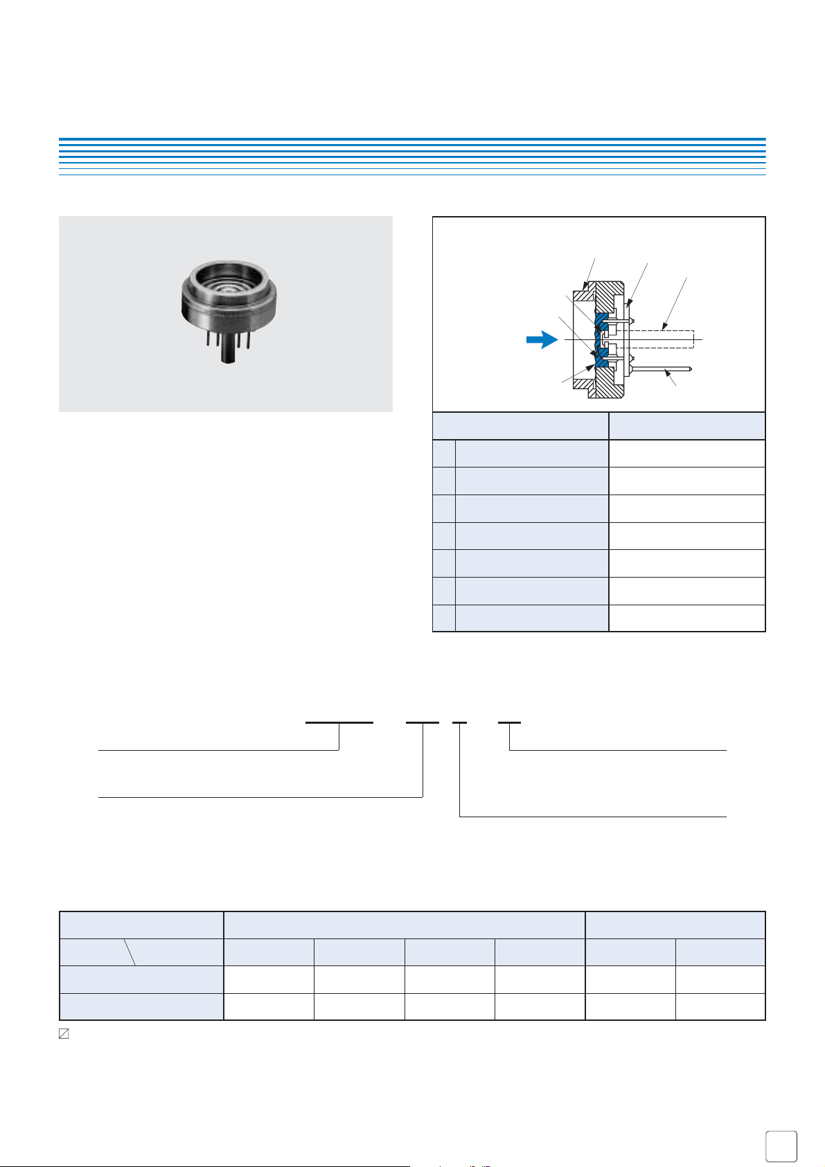
● Double diaphragm structure
● Two pressure references to choose from Gauge and
Absolute
● Built-in temperature compensation function (0 ~ 50 °C)
■ FEATURES
■ MODEL NUMBER DESIGNATION
Part name Material
Compensation resistor board
Silicone oil
Silicone
SUS 316L
Ceramic
Iron+gold-plated
SUS 316L
Copper+gold-plated
Sealed liquid
Sensor chip
Vent hole (Gauge type only)
Stainless steel diaphragm
Pressure port
Terminal pin
1
2
3
4
5
6
7
INTERNAL STRUCTURE
P-8300 - 102 A - 05
Series name Thermal error
05 : ± 0.05 % F.S./°C
10 : ± 0.1 % F.S./°C
Rated pressure range
351 : 0 ~ 34.3 kPa {0 ~ 0.35 kgf/cm2}
501 : 0 ~ 49.0 kPa {0 ~ 0.5 kgf/cm
2
}
102 : 0 ~ 98.1 kPa {0 ~ 1 kgf/cm
2
}
352 : 0 ~ 343 kPa {0 ~ 3.5 kgf/cm
2
}
103 : 0 ~ 981 kPa {0 ~ 10 kgf/cm
2
}
Pressure reference
G : Gauge
A : Absolute
PRESSURE TRANSDUCERS
P-8300
■ LIST OF MODEL NUMBERS
Pressure reference Gauge Absolute
0 ~ 49.0 0 ~ 98.1 0 ~ 343 0 ~ 981 0 ~ 34.3 0 ~ 98.1
{0 ~ 0.5} {0 ~ 1} {0 ~ 3.5} {0 ~ 10} {0 ~ 0.35} {0 ~ 1}
P-8300-501G-05 P-8300-102G-05 P-8300-352G-05 P-8300-103G-05 P-8300-351A-05 P-8300-102A-05
P-8300-501G-10 P-8300-102G-10 P-8300-352G-10 P-8300-103G-10 P-8300-351A-10 P-8300-102A-10
Rated pressure range
kPa {kgf/cm
2
}
± 0.05 % F.S./°C
± 0.1 % F.S./°C
Thermal error
: Not available
Verify the above model numbers when placing orders.
■
Specifications are subject to change without notice. Specifications in this catalog are for reference. The formal specification sheets will be submitted upon request.
COPAL ELECTRONIC
S
Oct,
2005
General specifications
Power
Analog output
P-8300
PRESSURE TRANSDUCERS
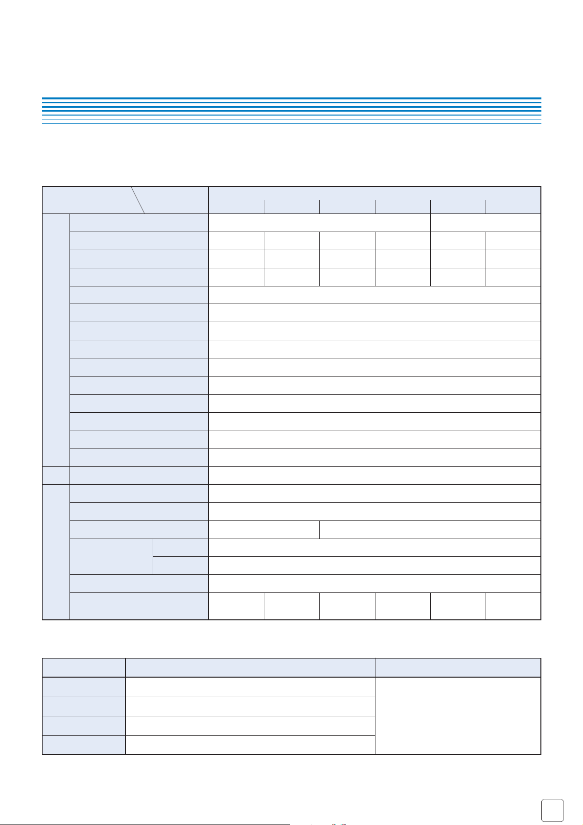
■ STANDARD SPECIFICATIONS
Item
Pressure reference
Rated pressure range
Maximum pressure
Break-down pressure
Operating temp. range
Compensated temp. range
Storage temp.
Operating humidity
Thermal error
(Reference temp.: 25 °C)
Excitation current
Offset voltage
Span voltage
Bridge resistance
Linearity/Hysteresis
Pressure medium
Insulation resistance
Dielectric strength
Sealed liquid
Response
Gravitational effect
(From vertical position to horizontal position)
Net weight
Model number
P-8300
501G 102G 352G 103G 351A 102A
Gauge Absolute
49.0
{0.5}
98.1
{1}
343
{3.5}
981
{10}
34.3
{0.35}
98.1
{1}
98.1
{1}
196
{2}
686
{7}
1961
{20}
103
{1.05}
196
{2}
147
{1.5}
294
{3}
1030
{10.5}
2942
{30}
147
{1.5}
294
{3}
Corrosive gases/liquids compatible with SUS316L
Approx. 20
± 5
100 ± 50
Approx. 2
Approx. 0.5 Approx. 0.3 Approx. 0.1 Approx. 0.05 Approx. 0.5 Approx. 0.3
4700 ± 30 %
1.5 (Constant current)
100 (500 V DC)
500 V AC, 60 s (Leakage current 1 mA maximum)
Silicone oil
0 ~ 50
35 ~ 85 (No condensation)
− 20 ~ 70 (Atmospheric pressure, humidity 65 %RH maximum)
− 20 ~ 70
± 0.3 ± 0.5
± 0.05/0.10
± 0.05/0.10
kPa {kgf/cm
2
}
kPa {kgf/cm
2
}
kPa {kgf/cm
2
}
°C
°C
%RH
°C
ZERO %F.S./°C
%F.S.
SPAN %F.S./°C
mA DC
mV
mV
Ω
MΩ
minimum
ms
%F.S.
max.
g
● Unless otherwise specified, the specs are defined at an ambient temperature of 25±5 °C and excitation current of 1.5 mA DC.
❈ P-8300 series can be operated at the vacuum pressure.
■ ENVIRONMENTAL CHARACTERISTICS
Test item
Test conditions (At 25 ± 5 °C)
Permissible change
Vibration 10 ~ 500 Hz, 1.5 mm maximum/98.1 m/s2, 3 directions for 2 hours each
981 m/s
2
, 3 directions for 3 times each
0 ~ Rated pressure, 10
6
cycles
40 °C, 90 ~ 95 %RH, 240 hrs.
Offset voltage/Span voltage: ± 1 %F.S.
maximum each
Shock
Pressure cycling
Moisture resistance

■
Specifications are subject to change without notice. Specifications in this catalog are for reference. The formal specification sheets will be submitted upon request.
COPAL ELECTRONIC
S
Oct,
2005
P-8300
PRESSURE TRANSDUCERS
■ OUTLINE DIMENSIONS Unless otherwise specified, tolerance : ± 0.5 (Unit: mm)
PIN CONNECTION
1
2
3
4
G
Output
B
Output
C
Input
C
Input
B
Housing
● P-8300 Gauge type
P-8300
23.2±2
3 6.8
(12)
1
14.8
4 × 2.54
1
2
3
4
G
23.5
19.8±0.1
16
3.5
6
5 –
0.7
Header
(Iron, gold-plated)
Ceramic board with temp. compensation resistors
Stainless steel diaphragm
Housing
(SUS 316L)
(SUS 316L)
Terminal pin
(Copper, Gold-plated)
φ
φ
φ
φφ
0
+0.2
● P-8300 Absolute type
4 × 2.54
Terminal pin
(Copper, Gold-plated)
19.8±0.1
φ
(22.8)
3
6.8
(12)
1
14.8
1
2
3
4
G
23.5
16
6
5 –
0.7
Ceramic board with temp.
compensation resistors
Stainless steel diaphragm
(SUS 316L)
Housing (SUS 316L)
0
+0.2
φ
φ
φ
Extra care should be taken with the diaphragm part. Do not touch the diaphragm directly to avoid damaging the diaphragm.
■
INTERNAL ELECTRICAL SCHEMATICS
■
INSTALLATION EXAMPLES
(Unit: mm)
● An “O” ring P20 (conforms to JIS B 2401) is provided as
accessory. Make the mounting bore diameters
φ
24 and φ20
± 0.1, and the surface-roughness as 6.3 S (▽▽▽).
+0.06
0
20 ± 0.1
Applied press.
φ
8.6
φ
21
+0.1
0
φ
24
φ
30
+0.06
0
Thick film resistors for temp. compensation
G
1 (+)
Output
4 (+)
Input
3 (–)
2 (–)
 Loading...