

DM4-2067
NIDEC COPAL CORPORATION
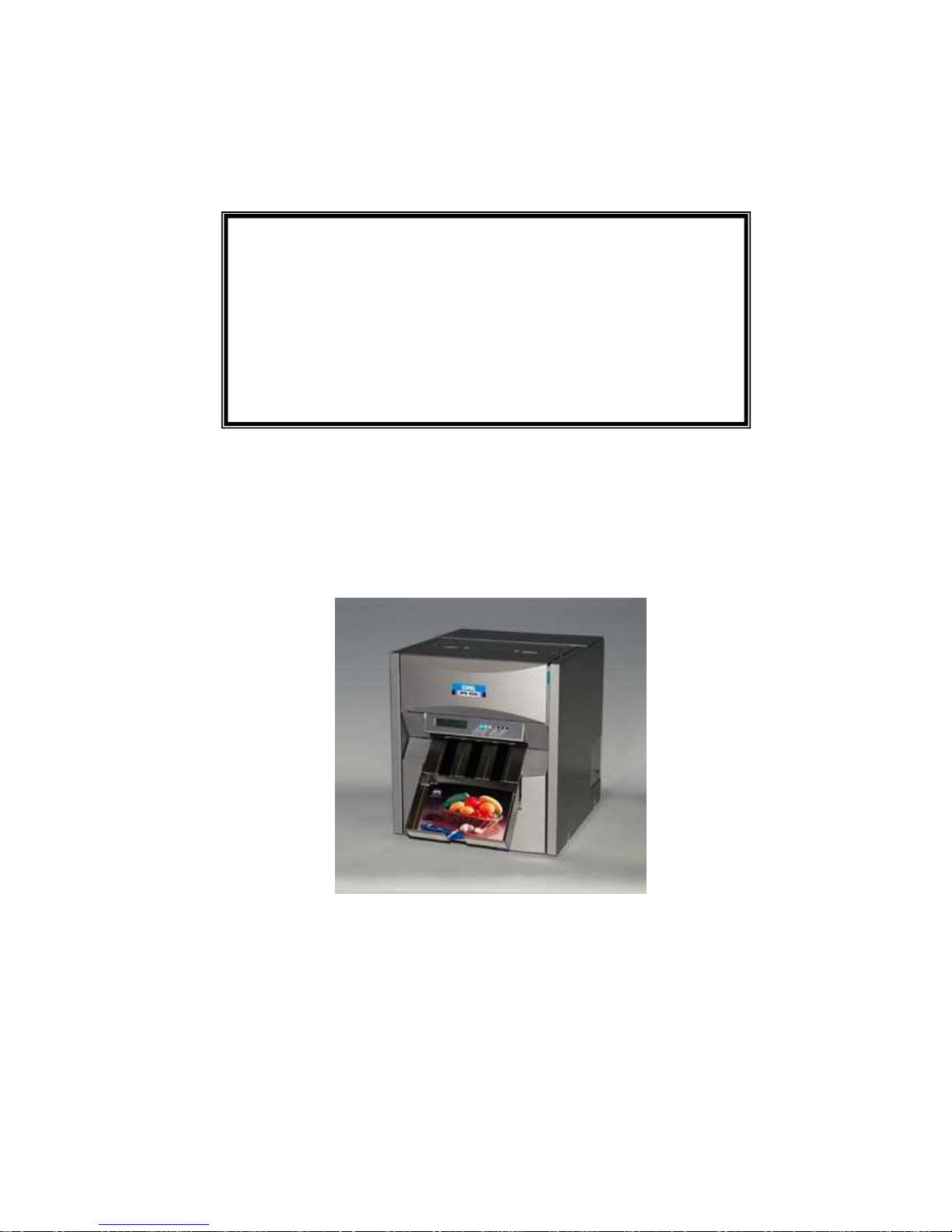
DPB-1500
INSTRUCTION
First Edition
January 2005

FCC Compliance Statement
WARNING
Changes or modifications not expressly approved by the party responsible for compliance could
void the user’s authority to operate the equipment.
Properly shielded and grounded cable and connectors must be used for connection to host
computer and / or peripherals in order to meet FCC emission limits.
NOTICE
Operation is subject to the following two conditions
(1) This device may not cause interference, and
(2) This device must accept any interference received, including interference that may cause
undesired operation of the device
This equipment has been tested and found to comply with the limits for a Class B digital device,
pursuant to part 15 of the FCC Rules. These limits are designed to provide reasonable protection
against harmful interference in a residential installation.
This equipment generates, uses and can radiate radio frequency energy and, if not installed and
used in accordance with the instruction, may cause harmful interference to radio communications.
However, there is no guarantee that interference will not occur in a particular installation. If this
equipment does cause harmful interference to radio or television reception, which can be
determined by turning the equipment off and on, the user is encouraged to try to correct the
interference by one or more of the following measures:
- Reorient or relocate receiving antenna.
- Increase the separation between the equipment and receiver.
- Connect the equipment into an outlet on a circuit different from that to which the receiver
is connected.
- Consult the dealer or an experienced radio/TV technician for help.

CONTENTS
Safety Precautions................................................................................................1
During installation.........................................................................................2
Environmental Consideration........................................................................2
During operation...........................................................................................3
During maintenance......................................................................................4
Other precautions.........................................................................................4
Handing of the print media............................................................................4
Preparation............................................................................................................5
Unpack .........................................................................................................5
Installation ....................................................................................................5
Changing paper width...................................................................................6
Printer drivers ...............................................................................................7
1. Windows 2000/XP printer driver...........................................................7
1.1 Plug and Play Installation for the Printer Driver............................... 7
1.2 Printer Driver Settings......................................................................9
- Selection of Paper Size...................................................................9
- Set up for print size “6x4inchX2” ...................................................10
- Set up for Print Mode (Hi-Speed / Hi-Quality)................................11
INSTRUCTION.....................................................................................................12
1. Overall View ................................................................................................12
(1) Front..................................................................................................12
(2) Rear..................................................................................................12
(3) Ink Ribbon Tray Section....................................................................13
(4) Print Head Section.............................................................................13
(5) Roll Paper Tray Section.....................................................................14
2. Operating Panel ..........................................................................................15
(1) Operating Panel LED........................................................................15
(2) Panel Switches..................................................................................16
3. Print media ..................................................................................................17
(1) Loading the roll paper........................................................................17
(2) Loading the ink ribbon.......................................................................22
(3) Printing .............................................................................................24

4. Daily Maintenance ........................................................................................25
Weekly Maintenance .................................................................................26
5. Troubleshooting ...........................................................................................27
(1) In case of ribbon error .......................................................................27
(2) In case of a paper transport error......................................................28
6. Error Messages.............................................................................................29
(1) Error messages upon startup............................................................29
(2) Recoverable Errors...........................................................................31
7. Specifications ...............................................................................................33

1
Safety Precautions
Please be sure to read this entire manual before using the product.
Pay special attention to this section “Safety Precautions”.
The precautions listed herein are designed to provide for safe operation of the product, and
to protect the user from experiencing bodily harm and property damage.
Safety notices herein are presented in two formats, “Warning” and “Caution” -- depending on the
degree of danger associated with accidental or other misuse of the product:
Be sure to keep this instruction manual in a safe and readily accessible location.
WARNING:
Failure to follow warning could result in
death or serious injury.
CAUTION:
Failure to follow caution could result in
minor bodily injury or property damage.
2
During installation
Environmental Considerations:
Ensure the room temperature is between 10 and 30 degrees C (50 and 85 degrees F), with
relative humidity between 30 and 70%.
Do not place unit where it will be exposed to direct sunlight or temporary freezing conditions.
CAUTION: Avoid placing the unit in areas of high humidity or dust
* Doing so could disable the unit
CAUTION: Do not allow the unit to block the ventilation holes
* Doing so could disable the unit
WARNING: Ensure the unit is properly grounded.
* Electrical discharge could cause shock and present a
fire hazard.
WARNING: Install the unit on a level surface or shelf which can
adequately handle the weight (approx. 24 Kg / 53 lbs)
* Bodily injury and property damage could result from the
unit falling from an unstable surface.

3
During operation
CAUTION: Some areas on the unit become hot and may burn the skin if
touched.
CAUTION: Do not insert hand or other objects into the power supply cooling
fan, as bodily injury and damage to the unit could result.
CAUTION: Be sure to use manufacturer-specified parts when replacing
consumables.
CAUTION: In the event of product break down, disconnect power to the unit
and call an authorized service facility.
WARNING: Provide adequate care to ensure water, chemicals or liquids do
not spill on or into the unit.
* Water and liquids can produce electric shock and present a fire
hazard.
WARNING: Do not print when cover panels are opened or removed.
* Electrical shock or other bodily harm could result.
WARNING: Do not touch the print head when power is on.
* High temperatures can burn skin.
WARNING: Always disconnect the power cord before cleaning the unit.
* Electrical shock or bodily injury could occur.
WARNING: Do not place the unit within reach of children.
* Electrical shock or bodily injury could occur.
WARNING: Do not bend or damage the power cable.
* This presents an electrical and fire hazard.
WARNING: Do not attempt to service the unit. Only qualified service
engineer should attempt to disassemble or repair the unit.
* Electrical shock or other bodily harm could result.
WARNING: Do not place objects on or near the unit’s ventilation area.
* This presents a fire hazard.
4
During maintenance
Other precautions
AC Power supplied to the unit should be between 100V and 240 V (Single phase)
Wear (cloth) gloves when handling paper. Undesirable printing (i.e. dirt and fingerprints)
could result should the paper come in contact with bare hands.
Handling of the print media
Storage: Keep the media away from high humidity and direct sunlight. Storage in cool
place is recommended. (Room temperature between 10 and 30 degrees C (50 and 85
degrees F), with relative humidity between 30 and 70%. Avoid dew condensation.)
Type of media: Use the genuine Copal print media. Use of the other make of media in the
Copal DPB-1500 printer may result into the bad influence to the print quality, malfunction of
the printer and/or may cause an serious damage to the printer which could not be repaired.
WARNING: Turn power switch OFF before attempting to perform any
maintenance to unit.
* The unit otherwise produces high voltage and hot surfaces which
can pose a danger to the person performing the maintenance.
WARNING: Do not force the safety interlock switch to the ON position.
* Electrical shock or bodily injury could occur.
WARNING: Ensure hands are dry before inserting power plug into outlet.
* Electrical shock or bodily injury could occur.

5
Preparation
Unpacking
Please find the following accessories when unpacking the DPB unit.
* Please store the test print carefully, as the print will be
of the reference for density check when the print head
would be replaced.
Installation
Setup the DPB unit and PC in a fixed location.
Step1. Connect the DPB unit to the PC. (USB2.0 cable should be prepared separately)
Step2. Connect the supplied power cable to the DPB-1500 unit and power supply.
(AC 100V – 240V, single phase).
Step3. Turn on the printer and PC.
Step4. Install the DPB-1500 printer driver (supplied on the CD-ROM) to the PC.
See: Printer drivers install procedures
Microsoft and Windows are registered trademarks of Microsoft Corporation in the United States and
other countries.
Warning: The DPB unit is heavy and requires 2 people to carry.
USB cable (USB2.0)
AC Power cable
DPB Back Side
Personal computer
OS: Windows 2000/XP
Power Switch
Cable connections
Accessories:
1. CD-ROM (Printer Driver, Manual,
Parts List, Adjustment Tool Software)
2. Print sample (shows factory
adjustment data.) *
3. Print tray
4. AC cable
1
2 3 4
6
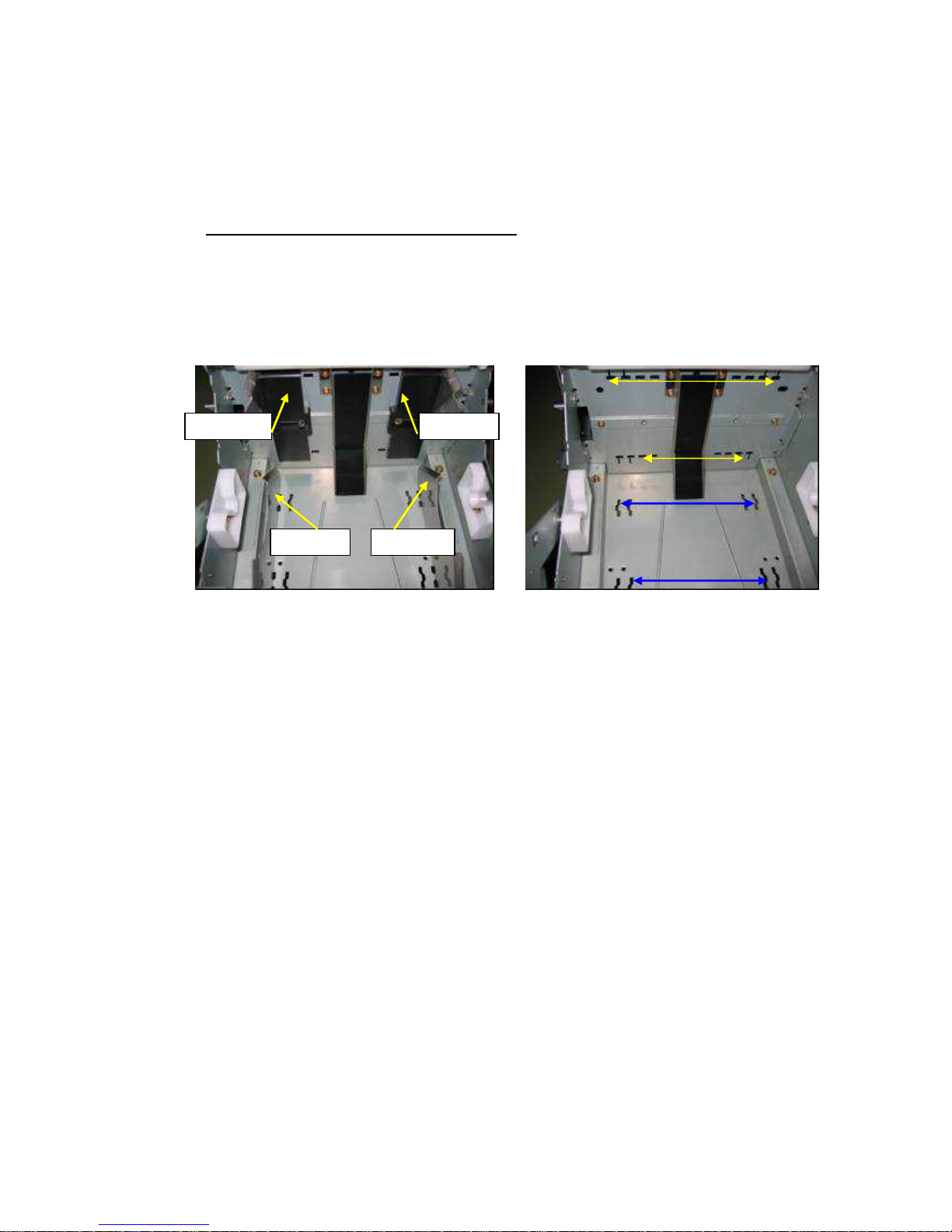
Changing paper width
* With moving the paper guides, the printer can be set to either 5-inch (127mm) width or
6-inch (152mm) width of paper.
* The default paper width is 6 inch (152 mm) at the factory shipment.
Replacing the left and right paper guides
Step1. Pull the paper tray forward. Fig1.
Step2. Remove the left and right guides, boards A and B. (Four guides in total, fixed by
one screw each) Fig1. Fig.2.
Step3. Set the guides to the grooves for the desired paper width.
Step4. Fix the left and right, A and B guides with screw. Fig1.
Left guide A
Left guide B
Right guide A
Right guide B
Fig.1
Fig.2 Guide
Guide A 127mm
Guide B 152mm
Guide B 127mm
Guide A 152mm

7
Printer drivers
1. Windows 2000/XP printer driver
* You need to log on as a Computer Administrator account when installing printer driver.
A Limited User cannot install it.
* After installation, ensure the printer is set to be Windows’ default printer, and select the
appropriate print format.
1.1 Plug and play Installation for the Printer Driver
1) Turn on computer and launch OS
2) Connect DPB to computer and turn on.
3) Plug & Play will start [Found New Hardware] dialog box will be display.
* File name W2k XP: Windows2000/XP
1. Found New Hardware will be displayed.
2. Hardware wizard Found New Hardware dialog box will be displayed.
3. Specify location where driver exists. Then click [Next].
Windows 2000 Windows XP
* Please select [Next>] button.
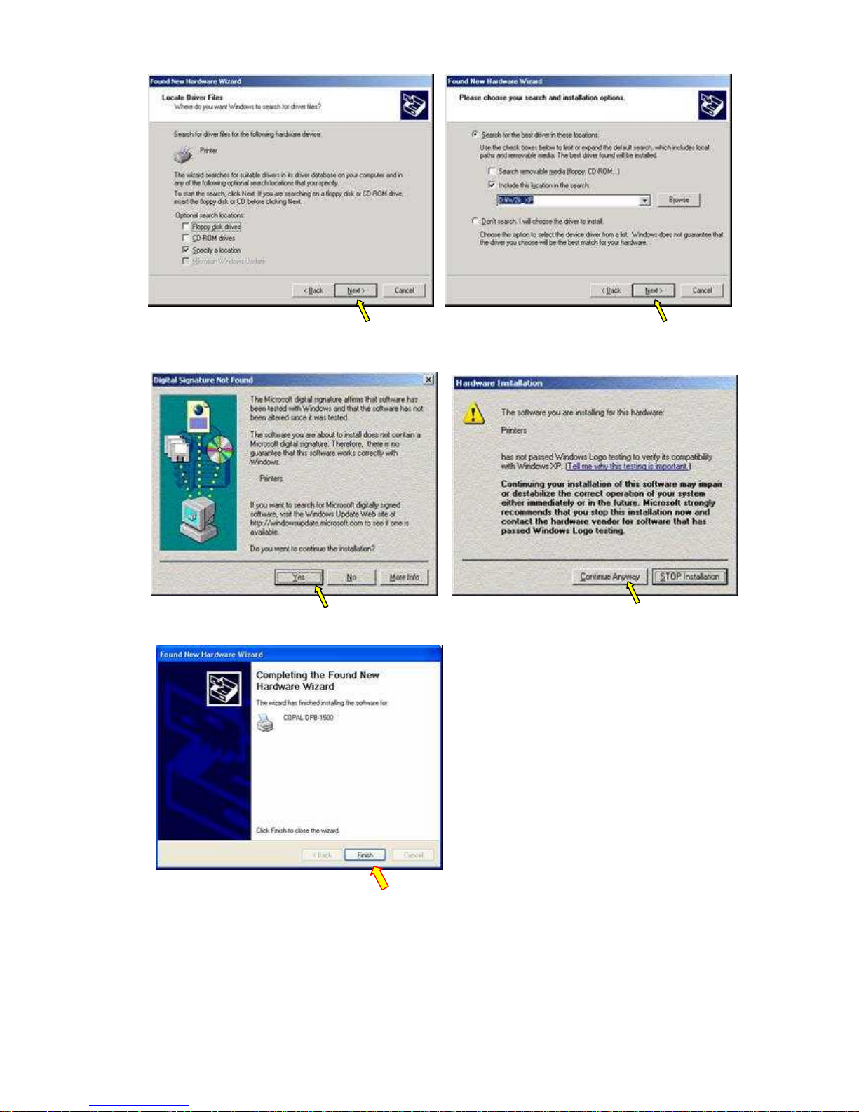
8
4.Select [YES] button Select [Continue Anyway] button
Windows 2000 Windows XP
5. Select [Finish] button, and DPB-1500 is registered

9
1.2 Printer Driver Settings
Printer default values can be set at printer property.
■ Selection of Paper Size
3. Printing Preference Dialog box
Select [Landscape] in the “Orientation”
box – Portrait or Landscape.
Select [Advance]
1. Select Properties of Printer
(COPAL DPB-1500)
2. COPAL DPB-1500 Properties Dialog
box

10
4. Click “Paper Size” and select paper size from drop 14down list
■ Set up for the print size “ 6 x 4inch x2”
Change the “Pages Per Sheet” from “1 “ to “2”
Select Paper Size
1. 5 x 3.5inch (127x89mm)
2. 6 x 4inch (152x102mm) Default
3. 5 x 7inch (127x178mm)
4. 6 x 8inch (152x203mm)
5. 6 x 9inch (152x230mm)
6. 6 x 4inch x 2 (152x102mm x2)
Note: “6 x 4inch x 2” format requires 6x9
format of media.
Change
1→2
Display
2 Sheet

11
■ Set up for Print Mode (Hi-Speed / Hi-Quality)
(Note) Hi-Speed is the default setting for regular print.
Hi-Speed: 300X300 dpi
Hi-Quality:300X600 dpi
Choice of Hi-Speed / Hi-Quality

12
INSTRUCTION
1. Overall View
(1) Front
(2) Rear
No. Name
1 Upper Cover
2 Ink Ribbon Tray
3 Display
4 Print Tray
5 LED lamp
6 Key Switch
7 Paper door
No. Name
1 Power Switch
I: ON O: OFF
2 AC Connector
3 USB2.0 Connector
WARNING:
To avoid electrical shock, always
ensure hands are dry when inserting
power cable.
Fig.4
Fig.3

13
(3) Ink Ribbon Tray Section
(4) Print Head Section
No. Names
1 Upper Cover
2 Print Head
3 Ink Ribbon supply
4 Ink Ribbon take up
5 Ink Ribbon Tray
WARNING:
The print head gets very hot.
Allow the head to cool for at least 5
minutes before handling.
No. Name
1 Print Head

14
(5) Roll Paper Tray Section
No.
Name
1 Release Lever
2 Control Card *
3 Pressure Roller
4 Slug Box
Fig.7 Print head assembly
WARNING:
The print head can break when
touched with bare hands.
Fig.8
* A control card is a factory option

15
2. Operating Panel
(1) Operating Panel LED
LED Lighting Status
Lit Power Switch ON (indicates ready status)
POWER Flashing --------- Off Power Switch OFF
Lit Paper is loaded to the print position.
DATA Flashing Image data being transmitted
Off Paper is rewound and can be exchanged
Lit Error: Paper/ Ribbon Empty (replace paper / ribbon)
ERROR Flashing Error: Power needs to be cycled off/on
Off No Errors (OK to print)
Ready
0
POWER
DATA
ERROR
REWIND
CUT
REPRINT
Display
LED lamps Panel switches
Fig.9
LED Push button switches
Display
POWER DATA ERROR

16
(2) Panel Switches
Switch Function
REWIND Rewind roll paper
CUT Cut paper tip (About 5 cm)
REPRINT
Repeat the last print
* The unit will be reset when this PEPRINT button is kept
pushing for more than five seconds.
REWIND
CUT
REPRINT

17
3. Print media
Ensure roll paper and ink ribbon is installed before printing.
(Note): Paper and ink ribbon maintenance
* Use manufacturer-specified materials.
* Place the unit where it will be in a cool and somewhat humid location, out of the
direct rays of the sun.
* Do not touch paper with bare hands.
(1) Loading the roll paper
(Note 1) Use cloth gloves when handling roll paper.
(This avoids transfer of fingerprints and other printing errors)
(Note 2) Do not shut off power to the unit when paper or ribbon runs out.
Normally both the paper and ribbon are replaced at the same time.
* Printing automatically re-starts after the roll paper is replaced.
* Data in process is erased should power be shut off.
* Approximately 500 PC-size papers can be printed with one ink ribbon and
roll paper set.
Step1: Remove print tray Step2: Draw out paper tray from front
Step3: Remove Slug Box (The slug Box is attached with a magnet)
Slug Box
Fig.12
Fig.10
Fig.11
Release

18
Step4: Pull the pressure release lever toward the front of the unit
Step5: Take out the new Roll Paper, inserting the supplied Paper Core
Fig.15
Paper Core Roll Paper
Fig.16
Pin
Tape
Fig.14
Fig.13
Release

19
Step6: Set the paper into the tray Step7: Set securely
Step8: Hold the paper tip, and again engage the Pressure Roller
* Securely fit the pins on both sides of the core
into the tray groove. Fig.18
(Note): The paper surface is to the rear.
Fig.19 Paper placement
Paper Surface
Paper tip
Rear
Front
Fig.17 Fig.18
PIN
Fig.20
Paper tip
Fig.21
Paper tip

20
Step9: Turn the gear to move the paper tip about 2mm into the roller
Step10: Mount the Slug Box
Step11: Set paper tray (Standard Size: 5x3.5, 6x4 inch)
As it opened a roll paper tray, it hitches a paper tray.
Fig.22
Paper tip 2mm
Gear
(Ensure it is securely locked)
(Note)
The roll paper tray cannot be pushed
back if the Slug Box isn’t mounted
Slug Box
Stopper lever
Fig.23
Paper Tray
Hook
Fig.24-1
Fig.24-2 Paper tray set condition

21
Option: Set universal tray. (Big Size / Standard Size) Fig.24-3, 24-4, 24-5
Step12: Push the roll paper tray into the main body.
(Note):
In the case that the paper tray is closed while the printer is turned ON, the printer is
initialized and exhausts leading edge of the paper roll by 20cm.
Fig.24-3 A: Plate
B: Big size tray
C:Standard size tray
A
Fig.24-5 Big tray is attached
Universal tray (Option)
Part No. P5A-F4572
The hook of the tray upper part is
hooked on a plate.
B
Fig.25-1
Fig.25-2 Universal tray

22
(2) Loading the ink ribbon.
Remove the Ink Ribbon tray from the unit.
Prepare the new roll of ribbon.
Step1. Open the upper cover. Step2. Push the lever
Step 3. Raise the upper cover Step 4. Remove the Ink Ribbon Tray
Fig.26
* The Take-Up Core gear is installed to the left
Gear
Ribbon
Take-up core
Fig.27
1.Push lever
2.Lift up
Fig.28
Fig.29
Fig.30

23
Step 5. Install the Ink Ribbon on the tray
Step 6. Set the Ink Ribbon Tray onto the body of the unit. Fig.33, 34
Place the take-up core into the set position.
Place the ribbon on the tension roller
and press it to the set position.
Fig.31 Setting the Ribbon (1)
Tension Roller
Setting the New Ribbon:
Turn the take-up core shaft more than once,
and remove a slack of the ribbon.
Take-up core
Fig.32 Setting the Ribbon Set (2)
Gear
Fig.34 Fig.33
Green marks

24
Step 7. Close Upper Cover securely, and close upper cover door Fig. 35, 36
(3) Printing
1. Turn on the printer and the PC.
2. Confirm that the LED is showing the ready status.
3. Check the print size and print mode with the printer driver.
4. Begin printing
(Note): There is a n interlock switch at the upper cover.
Should the upper cover be opened while printing, the interlock switch
will stop the unit. (Motor and head power will be shut down).
It is locked securely
Fig.35
Fig.36

25
4. Daily Maintenance
Ensure that dust & etc. does not go inside the printer..
Maintenance to the rollers, paper tray, print head and ribbon tray.
Paper tray section:
Cleaning of a base and a guide inside the paper tray.
Print head / Paper transport:
Cleaning the transport rollers:
* Normally a damp cloth is used.
* Ethyl Alcohol may be used for hard-to-remove items such as ribbon residue.
* Ethyl Alcohol may also be used to clean the print head.
(Note: Do not apply ethyl alcohol to the print head too much,
as it would cause a damage to the head.)
Fig.38 Paper Transport/Print Head
Paper Transport
Print Head
Fig.37 Paper Tray
Base
Roller

26
Ribbon tray section.
* Always keep the tension roller clean because, if the roller gets dirt, it would cause slip of
the ribbon that would result into the spoiled quality of the print and/or printer malfunction
* Wipe up lightly while soaking ethyl alcohol in the cloth and turning a tension roller.
(At least, once in a month)
* Remove the residue of the ribbon bobbin from its receiver. (Four receivers)
Weekly Maintenance
Fig.41 Bobbin tray (Four)
Cleaning part
Fig.39 Ribbon Tray
Tension roller
Fig.40 Tension roller
Cleaning part
(Note):
It would affects the print quality should
should the dust gets into the body.
Air Filter
Fig.42
Clean the air filter every week.
(Set the filter dry)
Replace an old air filter with the new air filter.

27
5. Troubleshooting
(Note) Paper and Ribbon End error messages are indicated with a solid red LED.
Do not turn off the unit, but rather replace the ribbon or paper with the DPB power on.
(1) In case of ribbon breakage
Turn of the printer.
1. Pull the ribbon tray out toward the front
2. Reel the ribbon on to the take up core (use tape), turn the core to set the
ribbon to its initial position. Fig.43
3. When in the middle of a print job, the paper printed so far is worthless, so
eject it. Turn on the power switch and once the red error LED turns off press the
tip cut switch (one cuts 5cm)
Ribbon supply Take up core
Over coat
Use tape to splice if necessary
Fig.43
Position of ribbon set
Set the position where an overcoat
(transparent) part comes between ribbon
supply and take-up cores.

28
(2) In case of a paper jam
Switch off the printer.
1. Pull the ink ribbon tray out and ensure there is no paper jam in the paper
transport area.
2. If there is a jam, use scissors, etc. to remove it. Fig.44
3. Paper tip is put into the paper guide. Fig.45
4. Turn on power, and once the red error LED turns off perform the following:
* If the paper tip is being printed, then press the Tip Cut key a number of times to
remove the printed area.
* If the paper tip has not been exposed, then press the Rewind key to rewind the
paper back into the paper tray.
* Pull the paper tray forward, and check to see if the paper tip is damaged.
If so, use scissors to cut the tip of the paper.
Cut at right angles
Fig.44
Paper guide
Fig.45

29
6. Error Messages
(1) Error messages upon startup “PC” = Personal Computer
Error No. Description
Error LED Flashing
LCD E01: Print head malfunction-up
PC
Error at Printer on USBXXX
Motor or Sensor Trouble.
Please restart printer.
01
Action Check head actuator mechanism sensor
Error LED Flashing
LCD E02: Print head malfunction-down
PC
Error at Printer on USBXXX
Motor or Sensor Trouble
Please restart printer.
02
Action Check head actuator mechanism sensor
Error LED Flashing
LCD E03: Faulty ink ribbon transport
PC
Error at Printer on USBXXX
Please check the position of ink ribbon.
Please restart printer.
03
Action Check head actuator mechanism sensor
Error LED Flashing
LCD E04: HDC error occurred
PC
Error at Printer on USBXXX
System Error
Please restart printer
04
Action The CPU PCB board needs to be replaced (10S-MAIN)
Error LED Flashing
LCD E05: Faulty paper transport - front
PC
Error at Printer on USBXXX
Paper Jam
Please restart printer
05
Action Check transport mechanism sensor
Error LED Flashing
LCD E06: Faulty paper transport - back
PC
Error at Printer on USBXXX
Paper Jamming
Please restart printer
06
Action Check transport mechanism sensor
Error LED Flashing
LCD E07: Paper cutter malfunction
PC
Error at Printer on USBXXX
Motor or Sensor Trouble
Please restart printer
07
Action Check cutter mechanism sensor

30
Error No. Description
Error LED Flashing
LCD E08: Timeout of CMD response
PC
Error at Printer on USBXXX
System Error.
Please restart printer.
08
Action Verify communication with host computer
Error LED Flashing
LCD E09: Writing FROM not successful
PC
Error at Printer on USBXXX
System Error
Please restart printer.
09
Action The CPU PCB board needs to be replaced (10S-MAIN)
Error LED Flashing
LCD E10: Power supply error
PC
Error at Printer on USBXXX
System Error
Please restart printer.
10
Action Replace power unit, verify power supply control
Error LED Flashing
LCD E11: Grip roller malfunction
PC
Error at Printer on USBXXX
Motor or Sensor Trouble.
Please restart printer.
11
Action Check roller actuator mechanism sensor

31
(2) Recoverable Errors
Error No. Description
Error LED Lit
LCD W50: Printer not ready
PC No message
50
Action Wait
Error LED Lit
LCD W51: ink ribbon end
PC
Warning W51 at Printer on USBXXX
Ribbon end.
Please replace an ink ribbon.
51
Action Check new ink ribbon sensor
Error LED Lit
LCD W52: Different type of ribbon
PC
Warning W52 at Printer on USBXXX
Media miss match.
Please place a proper size of paper or ink ribbon.
52*1
Action Reset with proper ribbon and check sensor
Error LED Lit
LCD W53: Ink ribbon cover open
PC
Warning W53 at Printer on USBXXX
A cover for an ink ribbon is opened.
Please close a cover.
53
Action Close cover securely and check sensor
Error LED Lit
LCD W54: Ink ribbon not set
PC
Warning W54 at Printer on USBXXX
An ink ribbon is not set.
Please set an ink ribbon.
54
Action Set the ribbon and check sensor
Error LED Lit
LCD W55: Paper end
PC
Warning W55 at Printer on USBXXX
A paper roll is empty.
Please replace a paper roll.
55
Action Exchange paper roll and check sensor
Error LED Lit
LCD W56: Paper not found
PC
Warning W56 at Printer on USBXXX
A paper is not loaded properly.
Please re-set a paper roll a printer.
56
Action Insert paper and check sensor

32
Error No. Description
Error LED Lit
LCD W57: Different type of paper
PC
Warning W57 at Printer on USBXXX
Media miss match.
Please place a proper size of paper or ink ribbon.
57
Action Reset with proper paper and check sensor
Error LED Lit
LCD W58: Paper door is opened
PC
Warning W58 at Printer on USBXXX
Paper door is open.
Please close a door.
58
Action Close paper tray securely and check sensor
Error LED Lit
LCD W59: Invalid command
PC No message.
59
Action Resend the proper command
Error LED Lit
LCD W60: Invalid parameter
PC No message
60
Action Retransmit the proper command parameter
Error LED Lit
LCD W73: Transferring not successful
PC
Error at Printer on USBXXX
Please Check USB Communication.
73
Action Check the USB cable and Power Supply

33
7. Specifications
Item Specifications
Type High Speed Dye Sublimation Printer
Print Resolution
Hi-Speed: 300 x 300dpi
Hi-Quality: 300 x 600dpi
Maximum Print Width 154mm
Print Speed
6X4inch
Hi-Speed: Approx. 12 Sec/Sheet
Hi-Quality: Approx. 19 Sec/Sheet
Interface USB 2.0
Buffer Memory 32MB
Paper Transport Roll paper
Print Size Borderless 5X3.5inch (127 x 89mm)
6X4inch (152 x 102mm)
5X7inch (127 x 178mm)
6X8inch (152 x 203mm)
6X9inch (152 x 230mm)
6X4inch X2 (152 x 102mm) X2
Paper Loading Tray Direct Loading
Paper Slug 5mm Width
Ink Ribbon YMC+OC
Ribbon Loading Tray set
Dimensions 300 (W) x 360 (D) x 340 (H) mm
Weight Approx. 24 Kg (53 lb)
Power Voltage
Power Consumption
100 – 240V AC
100VAC / 3A – 240VAC / 1.3A
Media Set 5X3.5inch 6X4inch 5X7inch 6X8, 6X9inch
Prints/Roll 500 500 250 225
 Loading...