

Coopra 40C Installation Manual
EN
Installation Manual
Heating Boiler . . . Type 40C
Wall hung, fan flue, room sealed gas boiler
CHAPTER 1. GENERAL
CHAPTER 2. INSTALLATION
CHAPTER 3. SUSPENDING THE UNIT
CHAPTER 4. COMMISSIONING
CHAPTER 5. TEMPERATURE REGULATIONS
CHAPTER 6. BURNER STATES and MONITORING
CHAPTER 7. MAINTENANCE
CHAPTER 8. MALFUNCTIONS
CE-CERTIFICATE
2007 E000129032

Coopra Advanced Heating Technologies Installation manual 40 EN
2
CONTENTS
CHAPTER 1. ………………………………………………………………………………..……….…………………………… 4
1.1. Technical data
1.2. Dimensional sketch…………………………………………………………………………………..……………………. 5
1.3. Unit components……………………………………………………………………………………………….…………… 6
1.4. Diagrams
1.4.1. Functional flow diagram………………………………………………………………………………….…… 7
1.4.2. Wiring diagram………………………………………………………………………………………...……….. 8
1.5. Operation………………………………………………………………………………………………………………..….. 9
1.6. Boiler types
1.6.1. Burner assy
1.6.2. Primair heat exchanger
1.6.3. Venturi
1.6.4. Pump
1.7. Conditions of delivery
1.8. Configuration of flue tube and air supply………………………………………………………………………………… 10
1.9. Environmental conditions
1.10. Permitted flue resistance
1.11. Heating of central heating water
1.12. Pump and hydraulic resistance…………………………………………………………………………………………. 11
1.13.
1.14. Standards / Guidelines
1.15. General safety regulations
1.16. Water quality
CHAPTER 2. INSTALLATION…………………………………………………………………………………………….…… 12
2.1.
2.2. Mounting the assembly bracket
2.3. Water and gas connections………………………………………..…………………………………………………….. 13
2.4. Seal on the waterside
2.5. Draconin connection
2.6. Electricity connection
CHAPTER 3. SUSPENDING THE UNIT ………………………………………………………………………………..……. 14
3.1. The unit
3.2. Suspension
3.3. Fitting the flue tube and air supply
3.3.1. Connecting the eccentric flue and air supply (2-pipe system)
3.3.2.
3.3.3. Connecting the concentric flue tube and air supply (60/100 mm adapter)
3.4. Condensation water drain/overpressure protection on drain
3.5. Connection block
3.5.1. On/off room thermostat (if applicable).
3.5.2. Modulating room thermostat (if applicable)………………………………………………………….………. 15
3.5.3. Connection for the external temperature sensor (if applicable).
3.6. Assembling the connection block
3.7. Placing the jacket
CHAPTER 4. COMMISSIONING…………………………………………………………………………………………..….. 16
4.1. Electrical connection 230 VAC
4.2. Main switch
4.3. Filling
4.4. Reading the water pressure
4.5. Venting
4.6. Chimney sweeper function
4.7. Gas / Air Ratio
4.8. Gas / Air adjustment ( CO
2
analysing)…………………………………………………………………………..……….. 17
4.9. Placing the jacket
4.10. Changing over to LPG-gas……………………………………………………………………………………….....….. 18
4.11. Display……………………………………………………………………………………………………………….…….. 19

Coopra Advanced Heating Technologies Installation manual 40 EN
3
4.12. Menu structure……………………………………………………………………………………………………………. 20
CHAPTER 5. TEMPERATURE REGULATIONS……………………………………………………………………….……. 21
5.1. Central heating
5.1.1. Central heating temperature regulation with on/off thermostat without outside temperature sensor
5.1.2. Central heating temperature regulation with on/off thermostat with outside temperature sensor
5.1.3. Central heating temperature regulation with modulating thermostat (Opentherm)……………………. 22
CHAPTER 6. BURNER STATES and MONITORING……………………………………………………………..……….. 23
6.1. Standby
6.2. Pre rinse
6.3. Ignition
6.4. In operation
6.5. Post-rinse………………………………………………………………………………………………………….………… 24
6.6. Lock-out
6.7. Pump test program
6.8. System pressure monitoring
6.9.
6.10. Temperature regulation
6.11. Limiter
6.12. Flue sensor………………………………………………………………………………………………………...……… 25
6.13. Frost protection
6.14. Glow plug protection
CHAPTER 7. MAINTENANCE……………………………………………………………………..………..………………… 26
7.1. ANNUAL MAINTENANCE
7.1.1. Checking the CO
2
percentage on full load
7.1.2. Measuring the load on the unit
7.1.3. Checking the condensation water drain
7.1.4. Ionisation probe
7.1.5. Water pressure
CHAPTER 8. MALFUNCTIONS……………………………………………………………………………………………….. 27
8.1. Draining the unit
8.2. No signal on the display
8.3. Fault code 'U/d or U/O' (alternating U with a status code will appear on the display)
8.4. Unit does not respond to central heating heat demand
8.5.
8.6.
8.7. Check function of gas control
8.8. Measuring the fan impedance
8.9. Fitting instructions for the pressure sensor
8.10. Fitting instructions for the safety valve
8.11. Malfunction code 'F' (flashing)............................................................................................................................. 28
8.11.1. Gas control will not open (no voltage)
8.11.2. Gas control will not open (gas inlet pressure too high)
8.11.3. Gas control will not open (coils defective)
8.11.4. Gas/air mixture is not correctly adjusted
8.11.5. Check glow plug
8.11.6. Check ionisation current
8.11.7. Inspection / cleaning / replacement of the ionisation probe
8.11.8. Ionisation probe or ionisation cable makes short circuit with earth
8.11.9. Boiler pump
CE-CERTIFICATE…………………………………………………….…………………………………………………………. 30
Coopra Advanced Heating Technologies Installation manual 40 EN
4
CHAPTER 1.
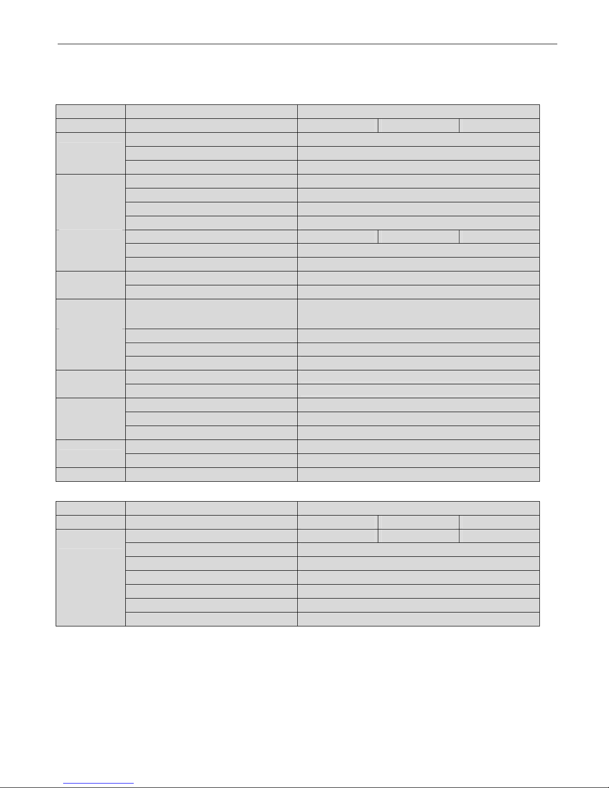
1.1. Technical data
Boiler type 40C
Gas type
natural gas G20 LPG gas G30/G31
Mains voltage / Frequency 230 V / 50 Hz
Power consumption (max.) 144 W
Electrical data
Thermostat voltage 24 V
Height 600 mm
Width 360 mm
Depth 300 mm
Dimensions and
weight
Weight 35 kg
CO2 8.2% - 8.8% 9.2% - 9.8%
CO (0% 02) 12 – 100 ppm
Emission value
NOX (0% O2) 10 – 30 ppm
at 80/60ºC < 70ºC
Flue gastemperature
at 50/30ºC < 35ºC
Maximum
chimney
resistance
Air feed and flue tube together
125 Pa
Gas Ø 15 mm
CH (flow and return) Ø 20 mm
Connections
Overflow Ø 15 mm
Eccentric
Ø 60 – Ø 60 mm or Ø 80 – Ø 80 mm
Air feed and flue
tube system
Concentric
Ø 60 / 100 mm or Ø 80 / 125 mm
Water contents 0.8 L
Max. temperature 90°C
Boiler heat
exchanger
Max. Water pressure 3 bar
Pump high 40 dB(A)
Sound level
Pump low 30 dB(A)
Certification
CE Identification number CE0063-AT3070
Boiler type 40C
Gas type
natural gas G20 LPG gas G30/G31
Nominal gas pressure 20 mbar 37/50 mbar
Heat input CH (gross) 8.1 – 41.1 kW
Heat input CH (net) 7.3 – 37.0 kW
Nominal output CH at 80/60ºC 7.2 – 36.0 kW
Nominal output CH at 50/30ºC 7.9 – 37.9 kW
Efficiency at 80/60ºC (net) Low load = 98.1 %; High load = 97.2 %
Gas technical
data type 40
Efficiency at 50/30ºC (net) Low load = 108.4 %; High load = 104.2 %
Coopra Advanced Heating Technologies Installation manual 40 EN
5
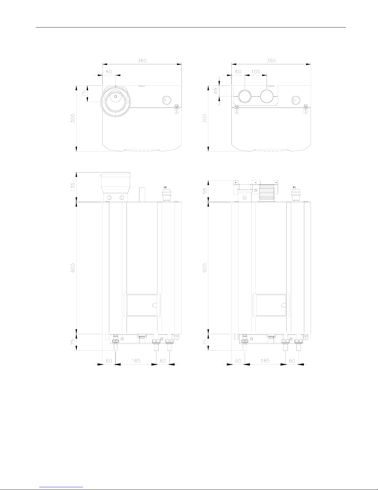
1.2. Dimensional sketch
Dimensions in mm
Free space
There must be sufficient space at the top and bottom to be able to suspend the unit and to be able to connect all feed and drain
pipes. Normally, roughly 300 mm is required.
It is recommended to leave a free space of 150 mm on the left (for servicing reasons) and 50 mm on the right of the unit.
The front of the unit must be easily accessible for servicing at all times.

Coopra Advanced Heating Technologies Installation manual 40 EN
6
1.3. Unit components
No Description Manufacturer
1 Primary heat exchanger Coopra
2
3 Pump Wilo
4
5
6 Glow plug Saint Gobain
7 Ionisation probe Sapco
8 Burner type 30 / 40 Furigas
9 Vapour tray Coopra
10 Gas valve Honeywell
11 Fan Vibo
12 Venturi type 40 Honeywell
13 Water pressure sensor Huba
14 Return sensor Honeywell
15 Flow sensor Honeywell
16 Safety device 3 bar Model 2000 Emmeti
18 N/A N/A
19 Flue gas temperature sensor Tasseron
20 Type plate Coopra
21 Condensation water overflow Coopra
22 Gas connection Coopra
23 Central heating return
24 Central heating flow

Coopra Advanced Heating Technologies Installation manual 40 EN
7
1.4. Diagrams
1.4.1. Functional flow diagram
F1
L
F2
N
+
-
FSP
-t
-t
-t
-t
-t
-t
BURNER
FLOW X17.6
X7.1
X7.2
X7.4
X14
X6.4
X6.1
X12
X8.6
X8.2
X4.4
X3.5
X3.4
X3.2
X3.1
X22.2
X22.1
X4.6
X4.5
X4.3
X4.1
X8.5
X8.4
X8.3
X8.1
X6.3
X9.2
X1.3
X10.2
X11.2
X9.1
X1.4
X10.1
X11.1
X16.7
X16.6
X16.3
X16.2
X15.2
X15.1
X15.3
X18.1
X18.3
X17.5
X19.1
X17.2
X19.2
X17.3
ROOM THERMOSTAT
24VAC
ROOM THERMOSTAT
230VAC
EbV THERMOSTAT
OPENTHERM
THERMOSTAT
PC CONNECTION
FLUE GAS
OUTSIDE
WATER PRESSURE +
P
-
RETURN
DHW INLET
EXTERNAL TANK
TANK THERMOSTAT
GLOW IGNITER
LN
IONISATION
GAS VALVE
230 VRAC
COMBUSTION FAN
325 VDC
ALARM CONTACT
MAXIMAL THERMOSTAT
(OPTIONAL)
DISPLAY
PE
230V 50 Hz N
L
FURIMAT-990
PE
PE
PE
DHW
CH
N
PE
PE
L1
L3
L2
N
X2.5
X2.4
X2.2
X2.1
X2.3
PUMP
230 VAC
PE
THREE-WAY VALVE
230 VAC

Coopra Advanced Heating Technologies Installation manual 40 EN
8
1.4.2. Wiring diagram

Coopra Advanced Heating Technologies Installation manual 40 EN
9
1.5. Operation
A fan sucks the air required for the combustion through the air
feed canal (A). Because the combustion air in the venturi
sucks an under pressure, the correct amount of gas (G) is
automatically added to the combustion air.
The flammable gas/air mixture thus obtained is fed to the
burner, via a mixing chamber, to be ignited at the surface of
the burner by a ceramic glow plug. The hot combustion gases
are efficiently fed through the heat exchanger, where they
give their heat to the water. The flue gases are fed outside,
through the flue tube (F), into a flue tube exhaust canal.
The condensation water (H
2
O) thus obtained is discharged
into the sewer.
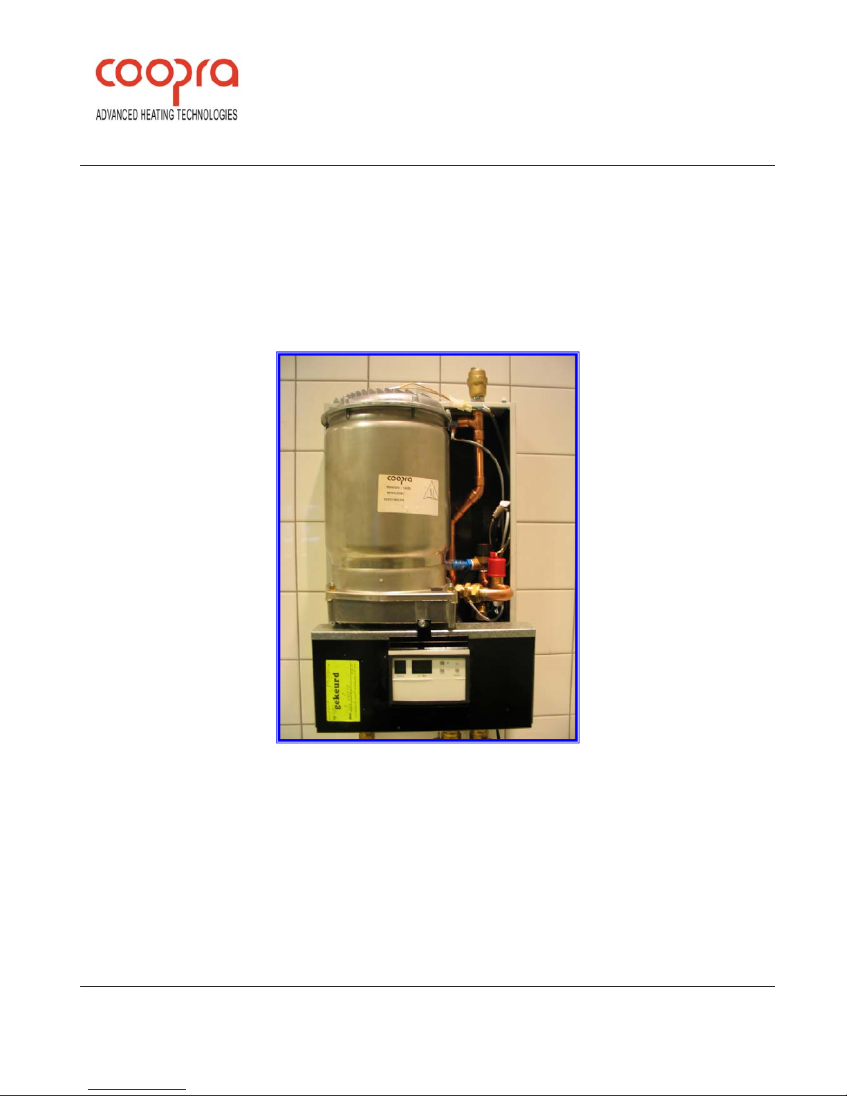
1.6. Boiler types
Coopra 40C
High efficiency boiler for central heating
only.
The Coopra boiler is a heating unit with compact dimensions
and a very high efficiency, with versions for domestic and
small commercial use for central heating.
The type plate, which specifies the type of gas etc. to be used,
for which the unit is set, is on the left side of the unit.
The unit is fixed to the wall with the aid of a separately
delivered assembly bracket or rear cabinet.
1.6.1. Burner assy
1.6.2. Primair heat exchanger
1.6.3. Venturi
1.6.4. Pump
1.7. Conditions of delivery
Coopra Advanced Heating Technologies b.v. supplies its
products according to the general conditions of delivery for the
metal and electro technical industry. Registered with the Clerk of
the District Court at Den Haag on 19 October 1998 under no.
119/1998.
Coopra Advanced Heating Technologies Installation manual 40 EN
10
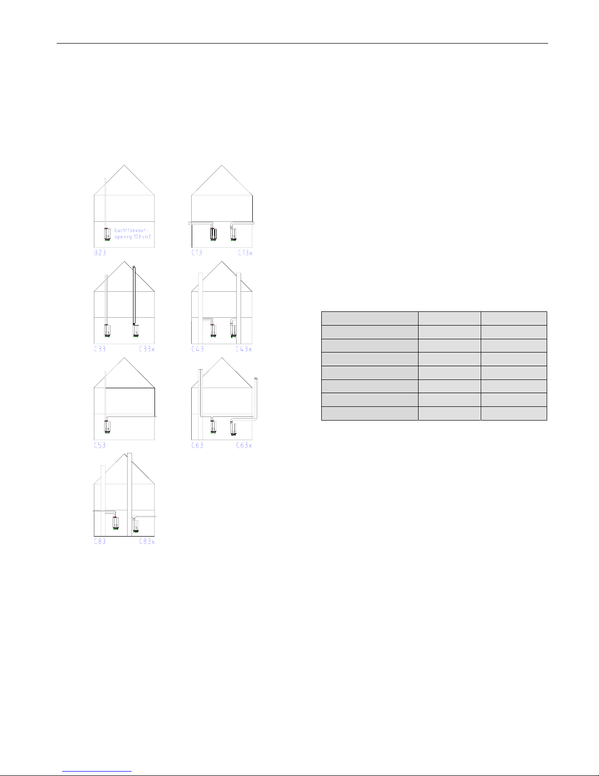
1.8. Configuration of flue tube and air supply
See figure below for an overview of possible configurations.
The units are approved for application on the drain systems:
B23, C13(x), C33(x), C43(x), C53, C63(x), C83(x).
Preferably use flue tube materials, roof ducts and exterior wall
ducts with a quality mark.
With plastic drain materials, use a unit with a flue gas
temperature sensor.
1.9. Environmental conditions
The area in which the unit is installed must satisfy the
applicable regulations.
The wall must be able to bear the weight of the unit (loaded
weight approx. 40 kg).
If you use a different assembly surface than a bricky wall of
sufficient thickness, you must select suitable fixtures yourself
and properly install the unit.
The unit may not be fitted in a chemically aggressive
environment.
The unit with air feed and flue gas exhaust satisfies the
requirements of protection class IP44 and may therefore be
installed in a wet area.
Although the unit is fitted with an internal frost protection, it
may not be exposed to extremely low ambient temperatures
(lower than -10°C).
1.10. Permitted flue resistance
Indication for the resistance values given in table below apply
to
- Flue exhaust flow rate of 61 m
3
/hour (at 70 ‘C)
- Supply air flow rate of 48 m
3
/hour (at 20 ‘C)
The total resistance of the flue tube and air supply together
may not be greater than 85 Pa.
Ø 100 mm Ø 80 mm
Type 40 (35)
Tube per metre 2,5 Pa 5.0 Pa
Bend 90°, R = 1.5 D 3.0 Pa 6.0 Pa
Bend 90°, R = 0.5 D 5.0 Pa 10.0 Pa
Bend 45°, R = 1.5 D 2.0 Pa 4.0 Pa
Bend 45°, R = 0.5 D 3.5 Pa 7.0 Pa
Roof duct 20.0 Pa 30.0 Pa
1.11. Heating of central heating water
If the room thermostat or space unit indicates that heat is
required for the central heating, the unit will heat the central
heating water as necessary. The power supplied is
automatically adapted to the heat required and is also
continuously variably adapted to the heat demand with the
use of an on/off thermostat.
When the thermostat indicates that the desired temperature
has been reached, the central heating water is no longer
heated. The central heating pump will continue to run for a
previously set time to distribute the heat evenly over the
heating installation.
A differential bypass valve must be installed on plants where it
may happen that various radiators are simultaneously
excluded from the circuit because of closure of control or zone
valves.
The by-pass valve must be mounted in the installation
between the flow and the return, provided that flow direction
indicated by arrow is respected.
To adjust the by-pass valve rotate knob of the graduated
scale on setting 2.5-3.0. This value corresponds to the meters
of pump head (m H2O).
Lock the screw on the groove knob.
 Loading...