

Coopra 40C, 15B, 15C, 37K, 37B Installation Manual
...
EN
Installation manual
(Boilers with printed circuit board type 585)
40C
Gas boiler for Heating E40C
2011 585 E

Coopra Advanced Heating Technologies Installation manual E40C
2
CONTENTS
CHAPTER 1. GENERAL ……………….………….. 3
Use of application
General safety regulations
Environmental conditions
Water quality
Standards / Guidelines
Conditions of delivery
1.1. Display …………………………………….…….. 4
1.2. PCB configuration
1.3. Operation indications
1.3.1. Normal state
1.3.2. Blocking state
1.3.3. Lock-out state
1.4. Menu Structure
1.4.1. View mode
1.5. Dimensional sketch
1.5.1. Technical data
1.5.2. Boiler components
1.6. Connection diagram
1.7. Operation
1.8. Boiler types
1.8.1. Coopra 40C
1.8.2. Technical characteristic
1.9. Electricity connection
1.10. Configuration of flue tube and air supply
1.10.1. Permitted flue resistance Type 40
1.11. Circulation pumps
1.11.1. Boiler pump
1.11.2. Secondary system pump
CHAPTER 2. INSTALLATION …………………….. 15
2.1. Mounting the assembly bracket
2.2. Water and gas connections
2.2.1. Gas connection
2.2.2. Water connections
2.2.3. Safety valve and Draconin connection
2.3. Expansion vessel
2.4. Filling and draining device
2.5. Dirt filter
2.6. Differential bypass valve
2.7. Unpacking the boiler
2.8. Fitting the flue tube and air supply
2.8.1. Connecting flue and air (2-pipe system)
2.8.2. Connecting flue/air adapter (80/125 mm)
2.8.3. Connecting flue/air adapter (60/100 mm)
2.9. Suspension
2.10. Green connector block
CHAPTER 3. REGULATIONS ……………..…….. 18
3.1. Central heating regulations
3.1.1. Modulation on flow sensor
3.1.2. Modulation on return sensor
3.1.3. Modulation on system sensor
3.2. Thermotats
3.2.1. On/off room thermostat
3.2.2. OpenTherm control
3.2.3. 0÷10V control
3.2.4. Outdoor sensor
CHAPTER 4. COMMISSIONING …………...…….. 20
4.1. Supply connection
4.2. Mains switch
4.3. Burner situation
4.3.1. Burner is on
4.3.2. Burner is off
4.4. Water pressure
4.5. Gas / Air Ratio
4.6.1. Full load
4.6.2. Low load
4.7. Changing over to LPG (G30/G31)
4.7.1. Full load on LPG (G30)
4.7.2. Low load on LPG (G30)
4.7.3. Labelling
CHAPTER 5. BURNER DEMAND and MONITORING
……………………………………………………….... 23
5.1. Standby
5.2. Pre purge
5.3. Ignition
5.4. In operation
5.5. Post-purge
5.6. Pump after run
5.7. Lock-out
5.8. Frost protection
5.9. System pressure monitoring
5.10. Flue temperature sensor
5.11. Limiter
5.12. Glow plug protection
CHAPTER 6. PERIODICAL MAINTENANCE …….. 25
6.1. Check the CO2 percentage on full load
6.2. Check the heat input
6.3. Clean the condensation water drain
6.4. Check the ionisation current
6.5. Water pressure
6.6. Service mode
CHAPTER 7. MALFUNCTIONS …..………...…….. 26
7.1. Serial connection
7.2. No signal on the display
7.3. Boiler does not respond to heat demand
7.4. Fitting instructions for the pressure sensor
7.5. Fitting instructions for the safety valve
7.6. Malfunction code 'F' (flashing)
7.6.1. Gas control will not open (no voltage)
7.6.2. Gas control will not open (gas inlet pressure high)
7.6.3. Gas control will not open (coils defective)
7.6.4. Check function of gas control
7.6.5. Check glow plug (no ignition)
7.6.6. Check the fan impedance
7.6.7. Gas/air mixture is not correctly adjusted
7.6.8. Inspection ionisation probe
7.6.9. Temperature sensors
CE-Certificate ………………..……………………… 28

Coopra Advanced Heating Technologies Installation manual E40C
3
CHAPTER 1. GENERAL
Use of application
The appliance is not intended for use by persons (including children) with reduced physical, sensory or mental
capabilities, or lack of experience and knowledge, unless they have been given supervision or instruction concerning
use of the appliance by a person responsible for their safety.
Children should be supervised to ensure that they do not play with the appliance.
General safety regulations
The installation may only be performed by a recognised installer.
Take note that internal parts of the boiler can carry a dangerous electrical voltage (230 Volt).
Take note that the boiler, the various pipes and the flue gas exhausted by the boiler can reach high temperatures (up to
90°C).
Before carrying out maintenance activities in or on the boiler, you must close the gas tap, switch off the electricity supply
and pull the mains plug out of the socket
Environmental conditions
The area in which the boiler is installed must satisfy the applicable regulations.
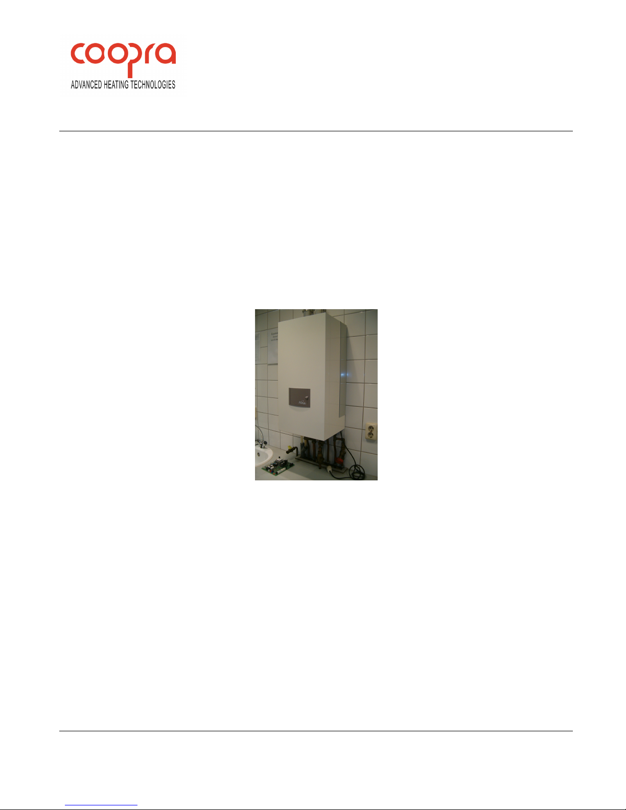
The wall must be able to bear the weight of the boiler (loaded weight approx. 40 kg).
If you use a different assembly surface than a bricky wall of sufficient thickness, you must select suitable fixtures
yourself and properly install the boiler.
The boiler may not be fitted in a chemically aggressive environment.
The boiler with air feed and flue gas exhaust satisfies the requirements of protection class IP44 and may therefore be
installed in a wet area.
Although the boiler is fitted with an internal frost protection, it may not be exposed to extremely low ambient
temperatures (lower than -10°C).
Water quality
Fill the system with tap water. The composition and quality of the system water has a direct effect on the performance of
the total system and the life of the boiler. At own risk is the addition and use of chemicals, water softeners, oxygen
binders, de-aerators, aerators and water filters as they increase the chance of malfunctions. Generally, the build-up of
undesired deposits can lead to leakages with fatal damage. No warranty when corrosive elements of certain additives
have attacked the boiler.
Regulations applicable to hot water
Ask for the locally applicable regulations at the local water company as they are different in some areas.
Standards / Guidelines
With the installation of the boiler, all local regulations must be followed, where applicable, including the provisions of the
following standards and guidelines:
• Building Regulations
• Regulations for natural gas installations
• Regulations for LPG (if applicable)
• Guidelines for existing gas installations
• Safety requirements for heating installations
• Safety provisions for low voltage installations
• General regulations for drinking water installations
• Water authority regulations
• Ventilation in dwellings
• Supply of combustion air and exhaust
• House sewerage in homes and dwellings
• Fire Brigade regulations
• Factory Act regulations
Conditions of delivery
Coopra Advanced Heating Technologies b.v. supplies its products according to the general conditions of delivery for the
metal and electro technical industry. Registered with the Clerk of the District Court at Den Haag on 19 October 1998 under
no. 119/1998.

Coopra Advanced Heating Technologies Installation manual E40C
4
1.1. Display
Open the door of the casing for display operation.
On the Status display is the status indication shown.
On the 3 right segments, the Reading display, values of
the temperature, pressure, etc are shown.
Push-buttons from left to right: MIN, PLUS and Set/Reset
Left of the Status display is a LED informing the situation
of the boiler.
LED is ON = burner is ON
LED is OFF = burner is OFF
LED is FLASHING = boiler is in LOCK-OUT
Right of the Reading display is a LED, active for TWIN
boilers only.
1.2. PCB configuration
Parameter A=2 is for single boilers 15B; 15C; 37K; 37B;
37C and also 40C
Parameter A=1 is for TWIN boiler 80C; set as SLAVE
Parameter A=0 is for TWIN boiler 80C; set as MASTER
Parameter H is to set for correct type of application.
1.3. Operation indications
To protect the system from the result of failures and/or
excessive conditions, several protection functions are
implemented.
1.3.1. Normal state
The boiler is stand-by or heating. During heating the
burner may be switched off temporarily when the
regulated water temperature is above setpoint.
1.3.2. Blocking state
Blocking protection is used when a certain condition must
block the system during this condition, but when this
condition is not valid anymore, the system automatically
may run normal again.
A blocking state is indicated by a fixed letter or number
on the Status display.
Depending on the blocking state the Reading display is
used normal or can have extra information regarding the
blocking state.
The blocking state cannot be reset by the user. The
control automatically goes to normal state when the
conditions are normal again.
1.3.3. Lock-out state
Lock-out protection is used when a certain condition
must lock the system until the user resets the system.
These conditions are often more safety related then
blocking conditions.
A lockout state is indicated by a blinking letter or number
on the left display character position. Depending on the
lockout state, the right characters of the display are
empty or have extra information regarding the lockout
state.
The Alarm output is active, and the running LED on the
display left hand side blinks.
To reset the system after a lock-out, press and hold the
Set/Reset button for more than 1 second.
Some lock-out situations can only be removed by power
restoration.
Note:
With repeating failures in short period of time always let
your installer or maintenance man check and repair
unconditionally.
(-)
button
(+)
button Set/Reset
Status
Reading
Coopra Advanced Heating Technologies Installation manual E40C
5
Status Reading
1.3.1. Normal state (continuous code)
P
With initialisation and after restoration of supply power de-aeration programme runs for 2 minutes.
The boiler pump and 3-way valve (if applicable) switch several times, with the purpose to move
eventual air out of the boiler; burner off
0
Stand-by (no heat demand)
C
Heating heat demand, temperature above setpoint, burner off
C.
Heating heat demand, temperature below setpoint, burner on
J
Heating heat demand, 3 minutes anti-cycling time, burner off
c
Pump after run heating mode, burner off
d
DHW heat demand, temperature return sensor of Combi-boiler above setpoint, burner off
d.
DHW heat demand, temperature return sensor of Combi-boiler below setpoint, burner on
b
HWS heat demand, temperature external cylinder above setpoint, burner off
b.
HWS heat demand, temperature external cylinder below setpoint, burner on
o
Frost protection 8°C; burner off, pump on
o.
Frost protection 3°C; burner on, pump on
C
flashing
Chimney sweeper function (ionisation current on the right hand segments)
Status Reading
1.3.2. Blocking state (continuous code)
2
Return sensor temperature 5°C above flow sensor temperature, pump on, burner off
6
Combi boiler internal tank sensor not connected or open (parameter H=01)
6.
Combi boiler internal tank sensor shortcut fault (parameter H=01)
9
Flow or return sensor temperature > 95°C
A
Flue gas sensor temperature > 100°C
b/r
Hot water on right unit of TWIN boiler
E
No SLAVE connected / PCB is set as MASTER, (parameter A=0)
SLA/01
No MASTER connected / PCB is set as SLAVE, (parameter A=1)
P
Water pressure low or high, display shows ‘P’+ pressure
t
Outdoor sensor summer switch on, burner off, (parameter O/t)
Status Reading
1.3.3. Lock-out state (flashing code)
1
Max delta temperature, differential temperature between flow and return sensor limits 50°C
1
Boiler does not pass temperature test. After burner start the flow sensor must rise 3°C more in
temperature than return sensor within 20 seconds (after 3 start attempts follows lock-out)
2
Flame signal lost 3 times during operation
5
Fan speed error (fan speed deviates > 30% from the speed setpoint)
8
Flame signal detected with closed gas valve
9
Eeprom programmed (to reset press the Set/Reset button)
A
Flue gas temperature > 100°C for more then 3 times within 30 minutes
E
Internal regulation fault / A/D conversion fault (depending type of error display shows ‘E’ or “EEE”)
E t1
Flow sensor open or shortcut fault
E t2
Return sensor open or shortcut fault
E t3
Flue gas sensor open or shortcut fault
F
Too many (4 times) consecutive start attempts
H
Flow or return sensor temperature > 105°C
O
Safety limiter contact is open (no limiter on this boiler, contacts bridged)
Coopra Advanced Heating Technologies Installation manual E40C
6
1.4. Menu structure
To enter the menu structure press and hold the Set/Reset button for longer than 10 seconds. The menu mode opens
with the password mode h=10. To unlock menu structure make h=18, use the (+) and (-) buttons. To go to the first
parameter press the Set/Reset button.
To change the parameter value, use the (+) and (-) buttons. To go to the next parameter press the Set/Reset button.
To save altered parameter settings, walk through the complete menu with the Set/Reset button until normal status
indication appears.
Timeout: When inside the menu structure the keys are untouched for 3 minutes, the system will switch back to the
normal status indication. Settings are not saved.
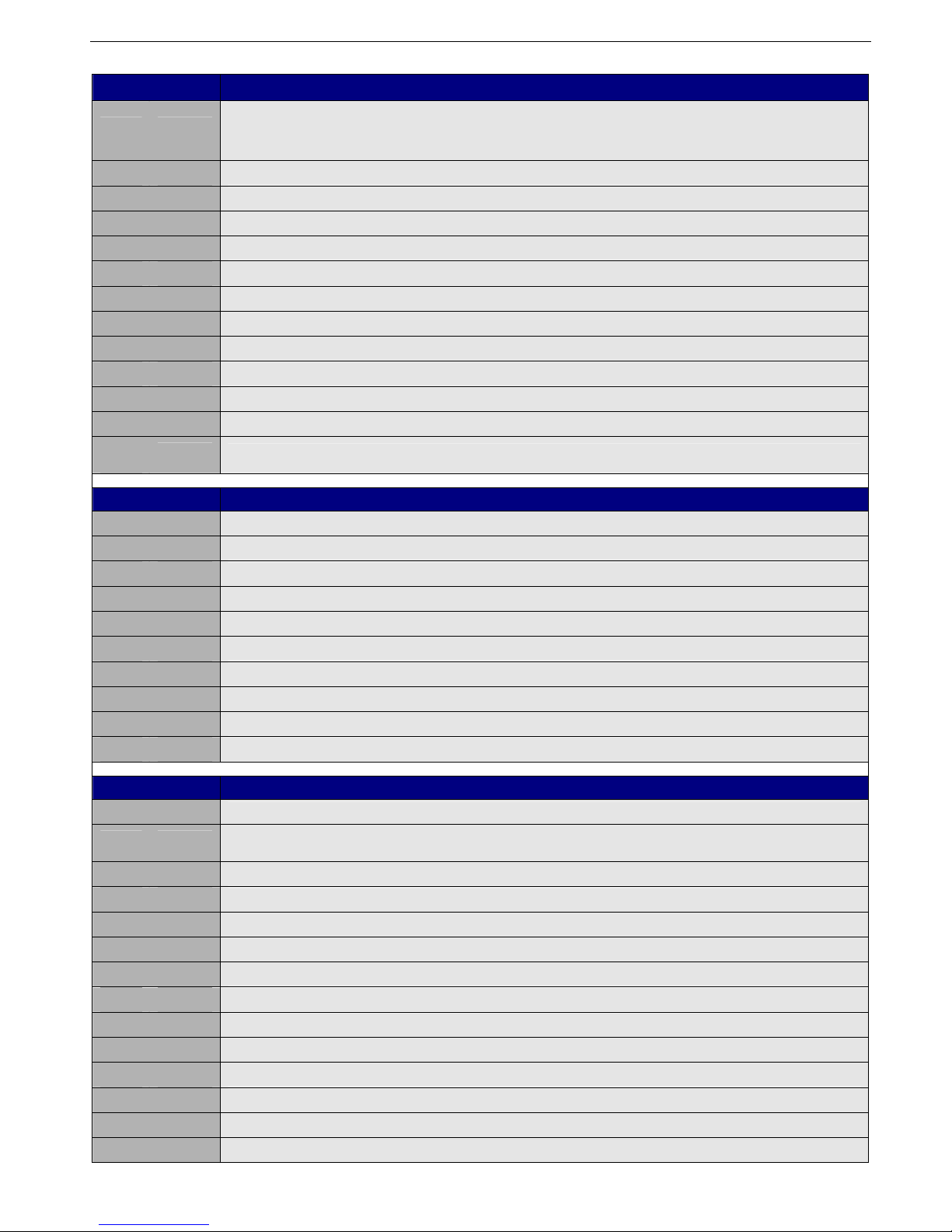
Menu structure
Status
parameter
Description Range
Factory
setting
h
Password protected
To unlock menu structure make h=18
10 - 99 h=10
C Heating max. flow temperature 25 - 90°C 82°C
C/r Modulation option
0 = Regulation on flow sensor (default)
1 = Regulation on return sensor or regulation on
system sensor
0
O Heating pump after run 1 - 25 min; CO=24uur 5 min
P Heating max input 45 - 100 % (fan 1800 – 5400 rpm) 100 %
A Boiler application
2=Standalone (for single boiler)
1=Slave (for TWIN right hand PCB)
0=Master (for TWIN left hand PCB)
2
H Type of application
00 = Adjustment for heating only
01 = Combi-boiler (with internal DHW tank)
02 = HWS storage cylinder 12kOhm (use for large
volume cylinders)
03 = HWS storage cylinder 10kOhm (use for large
volume cylinders)
04 = HWS storage cylinder 12kOhm (use for small
volume cylinders)
01
d (1) Setpoint temperature (Combi boiler) 40°C - 65°C 60°C
t (1) Hold temperature internal tank 40°C - 65°C 40°C
b (2) Setpoint temperature storage cylinder 25°C - 70°C 60°C
O/b (3) Basic temperature 10 - 90°C 40°C
O/S (3) Slope 01 - 99 20
O/d (3) Day reference temperature 10 - 90°C 40°C
O/t (3) Outdoor summer switch temperature 1 - 50°C 40°C
r
Return to “Factory setting”
Press (+) button for at least 5 seconds
Note: some settings do not return
= factory setting
= customised setting
u Configuration 0÷10V input
0 = Regulation on temperature
1 = Regulation on boiler output
0
o (4) Configuration of TWIN
01 = power mode (input 14,6 kW – 74,0 kW)
00 = comfort mode (input 7,3 kW – 74,0 kW)
01
F (2) Storage cylinder max flow temperature 65 - 90°C 85°C
S
Configuration pump
(2-stage pump regulation)
00 = automatic
= pump always high
= pump always low
00
Notes: (1) Active when H=1; (2) Active when H=2 or H=3 or H=4; (3) Active with outdoor sensor; (4) TWIN only

Coopra Advanced Heating Technologies Installation manual E40C
7
1.4.1. View mode
At the end of the menu structure, the view mode is shown.
The view mode is a reading only entry; no parameters can be changed in here.
The view mode is to enter directly.
Press the (+) button for at least 10 seconds. First upcoming is the water pressure P / u; in the Reading display on the
right hand segments is the actual water pressure in bar.
Press the Set/Reset button to next parameter.
To switch out of the view mode press the (-) button shortly or after timeout.
When the keys are untouched for 3 minutes, the system will switch out of the view mode automatically.
View mode
Single boiler
Status Description
P / u Actual water pressure left hand unit (in bar)
ﬤ / u
Setpoint temperature on flow sensor (in °C) (parameter C/r = 0)
Setpoint temperature on return or system sensor (in °C) (parameter C/r = 1)
1 / u Actual flow sensor temperature (in °C)
2 / u Actual return sensor temperature (in °C)
3 / u 0÷10V control (in Volt)
4 / u Outdoor sensor temperature (in °C)
5 / u Combi-boiler internal tank or external storage cylinder temperature (in °C)
6 / u Flue gas sensor temperature (in °C)
7 / u Flame signal (in µA DC)
9 / u Last lock-out
A / u Last blocking
d / u Actual system sensor temperature (in °C) (parameter C/r=1)
Coopra Advanced Heating Technologies Installation manual E40C
8
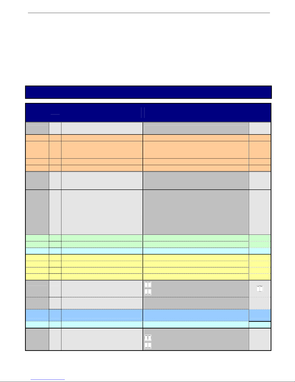
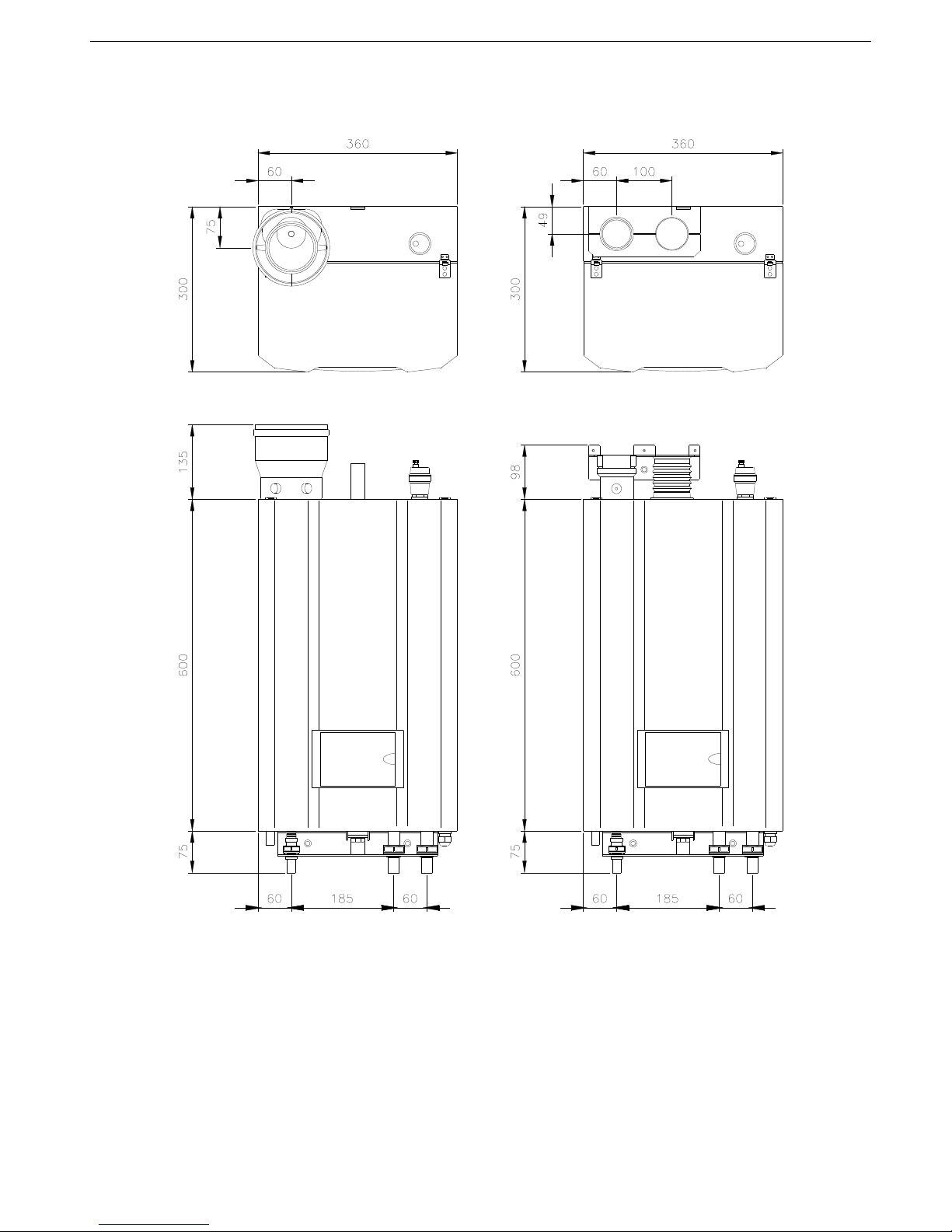
1.5. Dimensional sketch
Dimensions in mm
Free Space
There must be sufficient space at the top and bottom to be able to suspend the unit and to be able to connect all feed
and drain pipes. Normally, roughly 300 mm is required.
It is recommended to leave a free space of 150 mm on the left (for servicing reasons) and 50 mm on the right of the unit.
The front of the unit must be easily accessible for servicing at all times.

Coopra Advanced Heating Technologies Installation manual E40C
9
1.5.1. Technical data
Boiler type
35C
power reduced boiler to meet Italian market
Gas type
natural gas G20 natural gas G25 LPG G30/G31
Nominal gas pressure 20 mbar 25 mbar 37/50 mbar
Heat input CH (gross) 8.1 – 38.5 kW
Heat input CH (net) 7.3 – 34.7 kW
Nominal output CH at 80/60ºC 7.2 – 33.7 kW
Nominal output CH at 50/30ºC 7.9 – 36.1 kW
Efficiency at 80/60ºC (net) Low load = 98.7 %; High load = 97.2 %
Gas technical
data
Efficiency at 50/30ºC (net) Low load = 108.3 %; High load = 104.1 %
Boiler type 40C
Gas type
natural gas G20 natural gas G25 LPG G30/G31
Mains voltage / Frequency 230 V / 50 Hz
Power consumption (max.) 144 W
Electrical data
Automatic recognition of thermostat
connection
(potential free contact)
on/off thermostat or
OpenTherm control
Height 700 mm
Width 360 mm
Depth 300 mm
Dimensions
and weight
Weight 35 kg
Heat input CH (gross) 8.1 – 41.1 kW
Heat input CH (net) 7.3 – 37.0 kW
Nominal output CH at 80/60ºC 7.2 – 36.0 kW
Nominal output CH at 50/30ºC 7.9 – 37.9 kW
Efficiency at 80/60ºC (net) Low load = 98.7 %; High load = 97.2 %
Gas technical
data
Efficiency at 50/30ºC (net) Low load = 108.4 %; High load = 104.2 %
CO2 on low-high fire 8.2% - 8.8% 8.2% - 8.8% 9.2% - 9.8%
CO (0% 02) on low-high fire 12 – 100 ppm
Emission value
NOX (0% O2) on low-high fire 10 – 30 ppm
at 80/60ºC < 70ºC
Flue gastemperature
at 50/30ºC < 35ºC
Maximum
chimney
resistance
Air feed and flue tube together
85 Pa
Gas Ø 15 mm
CH (flow and return) Ø 20 mm
Connections
Overflow Ø 15 mm
2-pipe system Ø 60 – Ø 60 mm or Ø 80 – Ø 80 mm
Air feed and
flue tube
system
Concentric system Ø 60 / 100 mm or Ø 80 / 125 mm
Water contents 0,8 L
Max. temperature 90°C
Boiler primary
heat
exchanger
Max. Water pressure 3 bar
Pump high 40 dB(A)
Sound level
Pump low 30 dB(A)
Certification
CE Identification number CE0063-AT3070
Coopra Advanced Heating Technologies Installation manual E40C
10
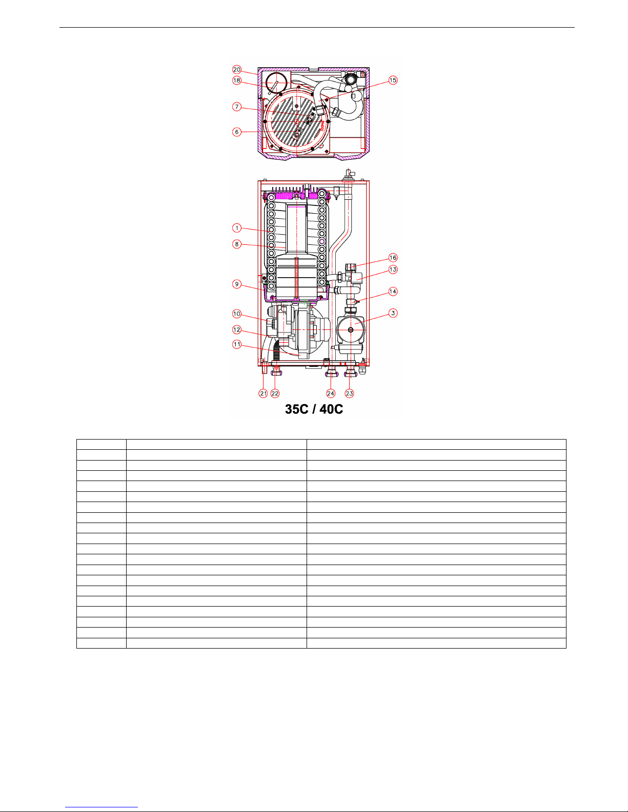
1.5.2. Boiler components
No Description
1 Primary heat exchanger
3 Pump
6 Glow plug
7 Ionisation probe
8 Burner type 30/40
9 Vapour tray
10 Gas valve
11 Fan
12 Venturi type 40
13 Water pressure sensor
14 Return sensor
15 Flow sensor
16 Safety device
18 Flue gas sensor
20 Type plate
21 Condensation water overflow
22 Gas connection
23 Central heating return connection
24 Central heating flow connection
 Loading...